Monotonic and Cyclic Simulation of Screw Fastened ... · Monotonic and Cyclic Simulation of...
216
Monotonic and Cyclic Simulation of Screw- Fastened Connections for Cold - Formed Steel Framing Chu Ding Thesis submitted to the faculty of the Virginia Polytechnic Institute and State University in partial fulfillment of the requirements for the degree of MASTER OF SCIENCE IN CIVIL ENGINEERING Cristopher D. Moen, Chair Matthew R. Eatherton Ioannis Koutromanos June 22, 2015 Blacksburg, VA Keywords: Cold-Formed Steel, ABAQUS, Finite Element Analysis, Screw-Fastened Connections
Transcript of Monotonic and Cyclic Simulation of Screw Fastened ... · Monotonic and Cyclic Simulation of...

Monotonic and Cyclic Simulation of Screw-Fastened Connections for Cold-
Formed Steel Framing
Chu Ding
Thesis submitted to the faculty of the
Virginia Polytechnic Institute and State University
in partial fulfillment of the requirements for the degree of
MASTER OF SCIENCE
IN
CIVIL ENGINEERING
Cristopher D. Moen, Chair
Matthew R. Eatherton
Ioannis Koutromanos
June 22, 2015
Blacksburg, VA
Keywords: Cold-Formed Steel, ABAQUS,
Finite Element Analysis, Screw-Fastened Connections

Monotonic and Cyclic Simulation of Screw-Fastened Connections for Cold-
Formed Steel Framing
Chu Ding
ABSTRACT
This thesis introduces an approach for modeling the monotonic and cyclic
response of cold-formed steel framing screw-fastened connections in commercial finite
element programs. The model proposed and verified herein lays the groundwork for
seismic modeling of cold-formed steel (CFS) framing including shear walls, gravity
walls, floor and roof diaphragms, and eventually whole building seismic analysis
considering individual fastener behavior and CFS structural components modeled with
thin-shell elements. An ABAQUS user element (UEL) is written and verified for a
nonlinear hysteretic model that can simulate pinching and strength and stiffness
degradation consistent with CFS screw-fastened connections. The user element is verified
at the connection level, including complex cyclic deformation paths, by comparing to
OpenSees connection simulation results. The connection model is employed in ABAQUS
shear wall simulations of recent monotonic and cyclic experiments where each screw-
fastened connection is represented as a UEL. The experimental and simulation results are
consistent for shear wall load-deformation response and cyclic strength and stiffness
degradation, confirming the validity of the UEL element and demonstrating that light

iii
steel framing performance can be directly studied with simulations as an alternative to
experiments.

iv
ACKNOWLEDGEMENTS
I would like to thank my advisor Dr. Moen for his help and guidance during my
research and studies at Virginia Tech. He gave great freedom and trust towards my
research. His encouragement and confidence can always keep me very motivated. He has
also shown me that structural engineer can also be one of the cool people, which makes
him a role model for me to follow in my future career in structural engineering. I like to
thank Dr. Eatherton for his invaluable advice on improving my connection model and
shear wall simulation. I especially need to thank Dr. Koutromanos for his help on solving
model divergence issues which is one of my biggest challenge in this research.
I also would like to thank my wonderful research colleagues, especially David
Padilla-Llano and Sebastien Corner. It was their friendliness and academic achievements
that brought me to this research. I need to thank Aritra Chatterjee and Guobo Bian for
their support and guidance on improving my simulation model. I want to also thank Dr.
Kara Peterman for providing me with her valuable connection test data.
Finally, I would like to thank my parents, Siyang Ding and Fengrong Dong. Their
unconditional support for me gave me solid foundation and determination to chase my
dream. I also want to thank Guolan. I must have been incredibly lucky to have met her at
Virginia Tech.
Go Hokies!

v
TABLE OF CONTENTS
ACKNOWLEDGEMENTS ........................................................................................................................ iv
TABLE OF CONTENTS ............................................................................................................................. v
LIST OF FIGURES ................................................................................................................................... viii
LIST OF TABLES ...................................................................................................................................... xii
INTRODUCTION ........................................................................................................... 1
1.1 Cold-Formed Steel Structures .......................................................................................................... 1
1.2 Cold-Formed Steel Framed Shear Walls .......................................................................................... 1
1.3 CFS-Sheathing Connections ............................................................................................................ 2
1.4 Research Objective ........................................................................................................................... 2
1.5 Thesis Organization ......................................................................................................................... 3
LITERATURE REVIEW ............................................................................................... 4
2.1 Experimental Studies ....................................................................................................................... 4
2.2 Numerical Studies ............................................................................................................................ 5
2.2.1 CASHEW model .................................................................................................................... 5
2.2.2 OpenSees model ..................................................................................................................... 8
2.2.3 ABAQUS model ....................................................................................................................11
PINCHING4 FORMULATION IN OPENSEES .........................................................14
3.1 Pinching4 Material ..........................................................................................................................14
3.2 Backbone Curve and Pinching Path ................................................................................................15
3.3 Pinching4 States ..............................................................................................................................16
3.3.1 State definition .......................................................................................................................16
3.3.2 State change ...........................................................................................................................17
3.4 Degradation .....................................................................................................................................17

vi
CONVERTING PINCHING4 TO ABAQUS ...............................................................21
4.1 General ............................................................................................................................................21
4.2 ABAQUS User Element Subroutine (UEL) ....................................................................................21
4.2.1 Introduction to user element subroutine (UEL) .....................................................................21
4.2.2 Linking UEL to ABAQUS ....................................................................................................21
4.3 Pinching4 Implementation in UEL..................................................................................................22
4.3.1 UEL framework .....................................................................................................................22
4.3.2 Pinching4 material implementation .......................................................................................23
4.3.3 Element formulation ..............................................................................................................25
ABAQUS CONNECTION UEL VERIFICATION .....................................................35
5.1 Verification Methodology ...............................................................................................................35
5.2 Verification of Backbone and Pinching Path ..................................................................................35
5.2.1 Verification model .................................................................................................................35
5.2.2 ABAQUS results against OpenSees ......................................................................................37
5.3 Verification of Degradation ............................................................................................................39
5.3.1 Verification model .................................................................................................................39
5.3.2 ABAQUS Results in Comparison to OpenSees .....................................................................39
5.4 Simulations of Screw-Fastened Steel-to-OSB Connections ............................................................41
NONLINEAR ANALYSIS OF SHEAR WALLS ........................................................45
6.1 Modeling methodology ...................................................................................................................45
6.2 Numerical Model ............................................................................................................................45
6.2.1 Model geometry .....................................................................................................................45
6.2.2 OSB sheathing modeling .......................................................................................................47
6.2.3 CFS members modeling ........................................................................................................49
6.2.4 Fastened connections modeling .............................................................................................51
6.3 Pushover Analysis ...........................................................................................................................51

vii
6.3.1 Influence of analysis procedures ............................................................................................51
6.3.2 Comparison to experiment .....................................................................................................55
6.4 Cyclic Analysis ...............................................................................................................................64
6.4.1 Fastener-only model study .....................................................................................................64
6.4.2 High-fidelity model ...............................................................................................................68
CONCLUSIONS AND FUTURE WORK ....................................................................72
REFERENCES ............................................................................................................................................74
APPENDIX A ANALYSIS CASES OF PINCHING4 MODEL VERIFICATION .......................78
A.1 Backbone and Pinching Paths Verification ................................................................................78
A.2 Degradation Verification ............................................................................................................85
APPENDIX B CONNECTION RESPONSE IN PUSHOVER ANALYSIS ...................................89
APPENDIX C USER ELEMENT SUBROUTINE IMPLICIT CODE (UEL) ...............................92
APPENDIX D USER ELEMENT SUBROUTINE EXPLICIT CODE (VUEL)..........................155

viii
LIST OF FIGURES
Fig. 1.1. Research objective flow chart............................................................................... 3
Fig. 2.1. Full-scale CFS framed building seismic test ........................................................ 4
Fig. 2.2. CFS-sheathing connection test and monotonic response ..................................... 5
Fig. 2.3. Shear wall model deformation model in CASHEW ............................................. 6
Fig. 2.4. Connection hysteresis model adopted in CASHEW ............................................ 7
Fig. 2.5. (a) Single spring model (b) Uncoupled spring pair model ................................... 8
Fig. 2.6. OpenSees CFS framed building model ................................................................ 9
Fig. 2.7. CFS framed shear wall model in OpenSees ....................................................... 10
Fig. 2.8. High-fidelity model of CFS framed shear wall in ABAQUS ............................. 11
Fig. 2.9. Nonlinear spring force–relative displacement relationship ................................ 12
Fig. 3.1. CFS-sheathing connection test results against calibrated Pinching4 hysteresis . 14
Fig. 3.2. Pinching4 material backbone curve and pinching paths .................................... 15
Fig. 3.3. Pinching4 material states .................................................................................... 16
Fig. 3.4. State change rules ............................................................................................... 17
Fig. 3.5. Unloading stiffness degradation ......................................................................... 19
Fig. 3.6. Reloading stiffness degradation.......................................................................... 20
Fig. 3.7. Strength degradation ........................................................................................... 20
Fig. 4.1. Work flow of ABAQUS and UEL ..................................................................... 22
Fig. 4.2. Work flow of computation inside UEL .............................................................. 23
Fig. 4.3. Uncoupled two-spring model ............................................................................. 26
Fig. 4.4. Oriented spring pair model ................................................................................. 27

ix
Fig. 4.5. Deformation quadrants of coupled two-spring model ........................................ 29
Fig. 4.6. Radial spring model ............................................................................................ 30
Fig. 4.7. Deformation quadrants of radial spring .............................................................. 31
Fig. 5.1. UEL verification model ...................................................................................... 36
Fig. 5.2. Cyclic loading protocol ...................................................................................... 37
Fig. 5.3. Verification case c54o6_1 (a) Load-deformation (b) Energy-cycle ................... 38
Fig. 5.4. Strength degradation verification case (a) Load-deformation (b) Cycle-energy 40
Fig. 5.5. Simulation of screw-fastened connections: 33 mils to 7/16’’ OSB.................... 42
Fig. 5.6. Simulation of screw-fastened connections: 54 mils to 7/16’’ OSB.................... 43
Fig. 5.7. Simulation of screw-fastened connections: 97 mils to 7/16’’ OSB.................... 44
Fig. 6.1. Shear wall numerical model geometry ............................................................... 46
Fig. 6.2. Bottom track stress distribution at maximum deformation unde pushover
analysis using elastic steel material .................................................................................. 49
Fig. 6.3. Bottom track stress distribution at maximum deformation unde pushover
analysis using plastic steel material .................................................................................. 50
Fig. 6.4. Load-deformation response of shear wall under monotonic loading ................. 52
Fig. 6.5. Comparison of numerical analysis results using different solution procedures . 54
Fig. 6.6. Comparison of numerical analysis result to experiment .................................... 56
Fig. 6.7. Shear wall general deformed shape at maximum shear wall displacement ....... 58
Fig. 6.8. Shear wall top track and ledger area Von Mises stress distribution at maximum
shear wall displacement .................................................................................................... 58

x
Fig. 6.9. Torsion of cold-formed steel studs of the shear wall at maximum lateral
deformation ....................................................................................................................... 59
Fig. 6.10. Shear wall bottom track and stud Von Mises stress distribution at maximum
shear wall deformation ...................................................................................................... 59
Fig. 6.11. Rotation of OSB sheathing at the maximum shear wall displacement ............. 60
Fig. 6.12. Distribution of failed connections on the shear wall during testing ................. 61
Fig. 6.13. Load-deformation response of the connections on the left stud bottom........... 62
Fig. 6.14. Load-deformation response of the connections on the right stud bottom ........ 63
Fig. 6.15. Load-deformation response of the connections on the bottom track ................ 64
Fig. 6.16. Fastener-only model ......................................................................................... 66
Fig. 6.17. Hysteretic response of fastener-only model ..................................................... 67
Fig. 6.18. Hysteretic response of one fastener in fastener-only model ............................. 68
Fig. 6.19. Cyclic response of high-fidelity shear wall model ........................................... 69
Fig. 6.20. Hysteretic response of one screw-fastened connection .................................... 70
Fig. 6.21. Deformed shape of the shear wall at the maximum load ................................. 71
Fig. 6.22. Deformed shape of the shear wall at the maximum displacement ................... 71
Fig. A.1. Verification case c33o6_1 (a) Load-deformation (b) Energy-cycle .................. 80
Fig. A.2. Verification case c33o12_1 (a) Load-deformation (b) Energy-cycle ................ 81
Fig. A.3. Verification case c54o6_1 (a) Load-deformation (b) Energy-cycle .................. 82
Fig. A.4. Verification case c54o12_1 (a) Load-deformation (b) Energy-cycle ................ 83
Fig. A.5. Verification case c97o6_1 (a) Load-deformation (b) Energy-cycle .................. 84
Fig. A.6. Unloading stiffness verification case: (a) Load-deformation (b) Cycle-energy 86

xi
Fig. A.7. Reloading stiffness verification case: (a) Load-deformation (b) Cycle-energy 87
Fig. A.8. Strength stiffness verification case: (a) Load-deformation (b) Cycle-energY .. 88
Fig. B.1. Force of left stud bottom connections a shear wall lateral displacement .......... 89
Fig. B.2. Force of right stud bottom connections against shear wall lateral displacement90
Fig. B.3. Force of bottom track connections against shear wall lateral displacement ...... 91

xii
LIST OF TABLES
Table 4.1. Local subroutines used in the UEL .................................................................. 23
Table 4.2. Local Pinching4 model subroutines ................................................................. 24
Table 5.1. Positive backbone parameters of steel-to-OSB connections ........................... 41
Table 5.2. Negative backbone parameters of steel-to-OSB connections .......................... 41
Table 5.3. Pinching path parameters of steel-to-OSB connections .................................. 41
Table 6.1. OSB Panel flexural and shear rigidity ............................................................. 48
Table 6.2. Converted OSB material modulus of elasticity ............................................... 48
Table 6.3. Isotropic hardening parameters ........................................................................ 50
Table 6.4. Steel-to-sheathing Pinching4 backbone parameters ........................................ 55
Table 6.5. Steel-to-sheathing Pinching4 pinching path parameters .................................. 55
Table A.1. Positive Pinching4 backbone parameters of verification cases ...................... 78
Table A.2. Negative Pinching4 backbone parameters of verification cases ..................... 78
Table A.3. Pinching path parameters of verification cases ............................................... 79
Table A.4. Backbone parameter of degradation verification cases .................................. 85
Table A.5. Degradation parameters of degradation verification cases ............................. 85

1
INTRODUCTION
1.1 Cold-Formed Steel Structures
Cold formed steel (CFS) is manufactured by rolling thin steel sheets into specific
shapes. With the development of first design specification in 1946, cold-formed steel
structure has been widely designed and constructed in the U.S. In recent decades, cold-
formed steel has been proved to be an efficient and low-cost solution to low-rise and mid-
rise buildings. In comparison to other types of structures, cold-formed steel structure
normally has shorter construction period and lower cost because of standardized
subsystem components. However, despite widespread usage, the behavior of cold-formed
steel structure under seismic loads and subsystem interactions have not been fully
understood, and performance-based seismic design methods have not been fully applied
to cold-formed steel structure.
1.2 Cold-Formed Steel Framed Shear Walls
Cold-formed steel (CFS) framed shear wall is a subsystem of cold-formed steel
structure, composed of cold-formed steel framing members and sheathing boards. The
connections between framing members and sheathing boards are created by mechanical
fasteners. These fastened connections ensure that framing members and sheathing boards
can work together under loads. As the main lateral force resisting system, cold-formed
steel framed shear walls are critical to structural seismic performance. But so far CFS
framed shear wall failure mechanisms are still not very clear and high-fidelity
computational modeling of CFS framed shear walls is needed for further research.

2
1.3 CFS-Sheathing Connections
The cold-formed steel (CFS) – sheathing connection is the key component in a
CFS framed shear wall subsystem. Under cyclic loading, the sequential failures of CFS-
sheathing connections control the overall shear wall behavior. Therefore, to perform
high-fidelity computational modeling of a CFS framed shear wall, the CFS-sheathing
connection behaviors need to be effectively simulated. However, the CFS-sheathing
connection hysteretic behavior is complicated, involving pinching and degradation. This
thesis develops a new element to provide an effective solution to simulate this behavior in
commercial finite element software.
1.4 Research Objective
Sheathed shear walls are typically the main lateral force resisting system in cold-
formed steel structures. Despite their importance in lateral resistance, high-fidelity
computational modeling of CFS framed shear walls is a challenge. The key to achieving
high-fidelity modeling is simulating CFS-sheathing connection behavior in a commercial
finite element software. Thus, the research objective herein is to propose a CFS-sheathing
connection model which fully simulates connection behavior and can be easily applied to
CFS framed shear wall model in ABAQUS. A flowchart as shown in Fig. 1.1 describes
this motivation. Hopefully, this CFS-sheathing connection model can be a stepping stone
towards more in-depth research on CFS framed shear walls with simulation as an
alternative to experiments.

3
Fig. 1.1. Research objective flow chart
1.5 Thesis Organization
This thesis begins with Chapter 1, the Introduction, which introduces cold-formed
steel framing and describes the research objective. Chapter 2, Literature Review,
summarizes past experimental and numerical research on CFS framed shear walls, and
concludes with a plan for taking converting a pinching material model in OpenSees to
commercial FEA software. Chapter 3 introduces the Pinching4 material model. Chapter 4
then explains the approach used to move the OpenSees Pinching4 material into
ABAQUS. Chapter 5 validates the Pinching4 material simulation results obtained from
ABAQUS against OpenSees results. Chapter 6 demonstrates how UEL can be applied to
shear wall modeling in ABAQUS. Finally, some conclusions and suggestions for future
work can be found in Chapter 7.
High-fidelity modeling
Experimental efforts
CFS framed shear wall
CFS-sheathing
connections simulation
• Subsystem capacity
• Failure mechanism
• Subsystem reliability
• Performance-based
CFS framing simulation

4
LITERATURE REVIEW
2.1 Experimental Studies
In order to fully understand the behavior of cold-formed steel buildings under
seismic excitation, a full-scale cold-formed steel building was tested on a shake table
(Peterman et al. 2014) as shown in Fig. 2.1. The full-scale cold-formed steel building
tests proved the building to be stiffer and stronger than what it was designed for. Even
though the building response was only the combined behaviors of all building
subsystems, the individual behaviors and their interactions were a challenge to
characterize, highlighting the important need for performance-based design methods
applicable to cold-formed steel structures.
Fig. 2.1. Full-scale CFS framed building seismic test. Peterman, K., Stehman, M.,
Buonopane, S., Nakata, N., Madsen, R., and Schafer, B. (2014). "SEISMIC
PERFORMANCE OF FULL-SCALE COLD-FORMED STEEL BUILDINGS.", Tenth U.S.
National Conference on Earthquake Engineering, Anchorage, Alaska. Used under fair use,
2015.

5
It has been shown with experiments and simulations that cold-formed steel to
sheathing connections dictates shear wall behavior (Buonopane et al. 2014; Liu et al.
2012; Moen et al. 2014). Experimental research (Peterman and Schafer 2013) as shown
in Fig. 2.2 was conducted on CFS-sheathing connections to characterize their hysteretic
response. In this research, 24 cold-formed steel to sheathing connections were tested
varying sheathing materials, steel ply thickness and fastener spacing to study their
influences. The test results were fitted to Pinching4 material model. The fitted Pinching4
material model served as important input for shear wall numerical studies.
(a) (b)
Fig. 2.2. CFS-sheathing connection test and monotonic response
2.2 Numerical Studies
2.2.1 CASHEW model
CASHEW stands for “Cyclic Analysis of Shear Walls” (Folz and Filiatrault
2000). It is software written for wood framed shear wall. In this software, framing
0 0.2 0.4 0.6 0.8 10
500
1000
1500
2000
2500
Displacement (in)
Load
(lb
)
54 mil, OSB, 12’’ spacing

6
members were modeled as rigid members with pin-ended connections. As result, the
framing system deformed as a system and provided no lateral stiffness. It was also
assumed that shear wall out-of-plane deformation could be ignored. From these
assumptions, the equilibrium equation were formulated by the principle of virtual work.
Only the virtual work contribution from sheathing and connections were considered.
Fig. 2.3. Shear wall model deformation model in CASHEW
Framing-sheathing connection were defined with a hysteresis model originally
proposed by (Foschi 1974). The hysteresis model can simulate pinching behavior with
strength and stiffness degradation. Connections were modeled as a pair of orthogonal
uncoupled springs both assigned with this hysteresis model. The reason behind this
modeling approach results from the complexity of connector behavior. The deformation
Top of Wall Force
UF Top of Wall Framing Displacement
FF
Framing Members
Sheathing Panels

7
trajectory of a connector under a monotonic analysis of the shear wall was found to be
almost unidirectional and a single nonlinear spring was supposed to be suitable for
monotonic analysis (Folz and Filiatrault 2000). However, under cyclic analysis, the
connector displacement trajectory was bi-directional making it difficult to differentiate
positive and negative connection displacement. To avoid this displacement sign issue,
uncoupled spring pair model was adopted in CASHEW.
Fig. 2.4. Connection hysteresis model adopted in CASHEW
This modeling approach results in an overestimation of connection strength and
stiffness. An internal adjustment strategy was adopted inside the program to overcome
this obstacle. The strategy reduced the connector spacing, and therefore the number of
connections, to match the energy absorbed in a monotonic analysis by the two-spring
model with energy in the one-spring model (Folz and Filiatrault 2000). With this

8
adjustment, connection strength and stiffness overestimation was alleviated but not
generally solved.
(a) (b)
Fig. 2.5. (a) Single spring model (b) Uncoupled spring pair model
CASHEW used displacement control and the Newton-Raphson method to find
shear wall load-deformation response. It was found that the shear wall global tangent
stiffness can become non-positive definite and the solution strategy would sometimes
struggle to converge. To overcome this numerical issue, CASHEW internally added an
axial spring at the top of shear wall to ensure that combine global tangent stiffness
remained positive definite during analysis (Ramm 1981).
2.2.2 OpenSees model
Two CFS framing modeling approaches have been tried out in OpenSees. One
approach is modeling CFS framed shear wall by X braces. This approach requires full-
scale shear wall testing to provide parameter input for X braces. An incremental dynamic
analysis model (Leng et al. 2013) was created in OpenSees that predicts time-history

9
response of CFS building under seismic executions. In this model, CFS framed shear
walls were modeled as X braces. The braces were assigned with the Pinching4 material to
simulate the hysteresis response of CFS framed shear walls. The Pinching4 material
parameters were fitted from full-scale shear wall tests (Liu et al. 2012a).
Fig. 2.6. OpenSees CFS framed building model
Another modeling approach is fastener-based modeling. This approach is inspired
by the discovery that CFS framed shear wall load-deformation curves highly resemble
CFS-sheathing connections. The principle is to include all CFS-sheathing connections on
shear walls to the shear wall model. The total shear wall response is the combined
behavior of CFS-sheathing connections, CFS framing and sheathing boards. One
advantage of this approach is that only CFS-sheathing connection tests are needed to
provide input for connection models. Models featuring monotonic and cyclic analysis
have been well studied in OpenSees (Bian et al. 2014; Buonopane et al. 2014). In these
OpenSees models (Fig.), the CFS-sheathing connections were modeled using
CoupledZeroLength element (Fig.). Pinching4 material was assigned to the
CoupleZeroLength elements to include connection hysteretic behaviors. Two features

10
make this element very suitable for modeling CFS-sheathing connections.
CoupledZeroLength element is a single shear spring capable of rotating its orientation in
the plane of the shear wall. Therefore, the connection strength and stiffness are not
overestimated in comparison to the uncoupled spring pair model discussed in previous
section. Also, CoupledZeroLength determines connection positive and negative
displacement by element orientation. This ensures that positive and negative
displacement can be differentiated for a bidirectional trajectory.
Fig. 2.7. CFS framed shear wall model in OpenSees
However, due to limitations of OpenSees, the behavior of CFS members cannot
be directly included in the analysis and sheathing flexibility is not well simulated. In
order to obtain more in-depth view of CFS shear wall behavior, a high-fidelity model
with freedom to include all members is needed.

11
2.2.3 ABAQUS model
To study shear wall failure mechanisms, Ngo (2014) developed some high-
fidelity models of CFS framed shear walls. Monotonic analysis were performed on shear
wall models and results were verified against shear wall test data (Liu et al. 2012a).
One important breakthrough of these models is directly modeling CFS framing
members and sheathing boards by shell elements. In these models, cold-formed steel
framing members and sheathing boards were modeled using 4-node shell element S4R in
ABAQUS. Finer meshing was applied to cold-formed steel members while wood-
sheathing panels were coarsely meshed.
Fig. 2.8. High-fidelity model of CFS framed shear wall in ABAQUS

12
Another breakthrough is modeling the CFS-sheathing connections by SPRINGA
elements (Fig.). SPRINGA is a 2-node axial spring element in ABAQUS. Two important
features make it suitable for modeling CFS-sheathing connections. Unlike conventional
spring elements, SPRINGA considers geometric nonlinearity. This means that its line of
action can be rotated during analysis instead of being fixed to X, Y or Z directions. This
feature avoids overestimation of connection strength and stiffness. Also, some level of
material nonlinearity is included in this model (Fig. 2.9).
Fig. 2.9. Nonlinear spring force–relative displacement relationship
However, shear wall model with CFS-sheathing connections modeled by
SPRINGA can only be used for monotonic analysis. Due to software limitations,
complete CFS-sheathing connection hysteresis cannot be defined in SPRINGA. With no
unloading and reloading paths defined, a shear wall model cannot achieve convergence
under cyclic loading. Besides, CFS-sheathing connection is normally modeled by a single
SPRINGA element (Ngo 2014). Therefore the SPRINGA displacement trajectory will be

13
bidirectional making it not possible to define positive and negative displacement. No
special algorithm is provided in SPRINGA to address this issue. To achieve high-fidelity
modeling applicable to both monotonic and cyclic analysis, ABAQUS needs an extension
that incorporates complete CFS-sheathing connection hysteresis and algorithm resolving
this bidirectional trajectory issue. The OpenSees Pinching4 model parameters and
implementation are introduced in the next chapter to prepare the reader for its mapping to
ABAQUS in Chapter 5.

14
PINCHING4 FORMULATION IN OPENSEES
3.1 Pinching4 Material
Pinching4 is an OpenSees material model that some CFS researchers used for
calibrating CFS-sheathing connection tests (Bian et al. 2014; Ngo 2014; Peterman and
Schafer 2013). The calibrated Pinching4 material parameters can represent realistic CFS-
sheathing hysteretic response curves (Fig.) which serve as a key input for computational
modeling of CFS framed shear walls.
Fig. 3.1. CFS-sheathing connection test results against calibrated Pinching4 hysteresis
Pinching4 is a one-dimensional material model written by Lowes et al. (2003) and
implemented in OpenSees (Mazzoni et al. 2006). Nonlinearity is included in this model
by a set of rules that control the shape of hysteresis. This model is evolutionary in
updating its strength envelope and unloading/reloading paths during analysis. These two
features make Pinching4 very suitable for simulating CFS-sheathing connection behavior.

15
3.2 Backbone Curve and Pinching Path
The Pinching4 material backbone curve is multilinear. The multilinearity allows
freedom for users to fully include the nonlinearity of CFS-sheathing connections
hysteresis. Both positive and negative branches need to be defined which allows the
Pinching4 backbone curve to be asymmetrical (Padilla-Llano et al. 2014). In total, 16
parameters are needed for defining a Pinching4 backbone curve. A typical Pinching4
backbone is shown in Fig. 3.2. The Pinching4 behavior is simulated by pinching paths.
The pinching paths define material reloading and unloading paths. The pinching paths are
not only controlled by user input parameters. Material loading history also affect the
pinching path shapes. Depending on the material maximum deformation and minimum
deformation, the pinching paths can be linear, bilinear or trilinear. There are six
parameters required for defining pinching paths.
Fig. 3.2. Pinching4 material backbone curve and pinching paths
pinching4
backbone
deformation
load
(ePd1, ePf1)
(ePd2, ePf2 )
(ePd3, ePf3 )
(ePd4, ePf4 )
(eNd1, eNf1)
(eNd2, eNf2 )
(eNd3, eNf3 )
(eNd4, eNf4 )
a
b
c
d
e
f
(dmin, f (dmin ))
(dmax , f (dmax ))
(rDispN . dmin, rForceN . f (dmin ))
(rDispP . dmax, rForceP . f (dmax ))
(*,uForceP . ePf3)
(*,uForceN . eNf3)
a =
b =
c =
d =
e =
f =

16
3.3 Pinching4 States
3.3.1 State definition
In Pinching4 material, there are four states, State 1, State 2, State 3 and State 4
(Fig. 3.3). Each state represents a set of material behavior. State 1 represents material
being loaded in the way that follows the backbone positive branch and State 2 represents
the backbone negative branch. The load path boundaries of State 1 and State 2 are two
points on the backbone curve corresponding to maximum and minimum deformation
respectively. State 3 and State 4 are reloading and unloading cases where all pinching and
degradation behaviors occur. For State 3 and State 4, the load paths can be trilinear,
bilinear or a straight line depending on load-deformation history. The boundaries of State
3 and State 4 are the maximum and minimum load-deformation points reached on
backbone curve.
Fig. 3.3. Pinching4 material states
1
3
2
4
deformation
load

17
3.3.2 State change
It is unlikely that a material is always loaded in one state. State change will occur
when loading direction is reversed or the material is loaded beyond the state boundaries.
When a state change occurs, the material behaviors in the new state will be used in
analysis. It is worth noting that certain state changes also trigger strength and stiffness
degradation.
Different states have different conditions for triggering state change. For State 1
and State 2, state change can occur only when there is reverse in loading direction. For
State 3 and State 4, both loading direction reversal and loading beyond state boundaries
can trigger state change. The state after state change is determined by certain rules as
shown in Fig. 3.4.
Fig. 3.4. State change rules
3.4 Degradation
In the Pinching4 material, damage rules were included to simulate material
deterioration. The deterioration includes unloading/reloading stiffness degradation and
1
2
43
no change in the direction of loading
change in the direction of loading
change in the direction of loading with
a large deformation increment

18
strength degradation. The amount of material degradation is determined by damage index
as shown in Eq. 3.1.
lim2max1
4
3
monotonic
ii
E
Ed
(3.1)
i = current increment number
i = degradation index at increment i
1 = degradation parameter 1
2 = degradation parameter 2
3 = degradation parameter 3
4 = degradation parameter 4
lim = degradation parameter limit
dmax = maximum portion of failure displacement ever
encountered
Ei = hysteretic energy at current increment i
Emonotonic = total energy achieved if loaded along backbone
curve to failure
ki = unloading stiffness degradation index at
increment i
di = reloading stiffness degradation index at
increment i
fi = strength degradation index at increment i

19
With damage index calculated, degradation can be easily applied to loading/unloading
stiffness and strength degradation.
For unloading stiffness degradation:
kii kk 10 (3.2)
Fig. 3.5. Unloading stiffness degradation
For reloading stiffness degradation:
dii dd 10maxmax (3.3)
deformation
load
k0
ki

20
Fig. 3.6. Reloading stiffness degradation
For strength degradation:
fii ff 10maxmax (3.4)
Fig. 3.7. Strength degradation
deformation
load(d max
) 1
(d max) 3(d max
) 2
deformation
load(f
max)1
(fmax
)3
(fmax
)2

21
CONVERTING PINCHING4 TO ABAQUS
4.1 General
As discussed in Chapter 2, current high-fidelity modeling of CFS framed shear
walls in ABAQUS is inhibited by the fact that ABAQUS does not have suitable material
or element for modeling CFS-sheathing connections. This chapter introduces a user
element subroutine (UEL) which brings the Pinching4 material into ABAQUS.
4.2 ABAQUS User Element Subroutine (UEL)
4.2.1 Introduction to user element subroutine (UEL)
ABAQUS has a comprehensive element library. However, there are still some
types of elements not available in its element library, especially elements with a special
purpose. To overcome this limitation, ABAQUS allows users to define their own
elements by programming a user element subroutine (UEL). A UEL is a FORTRAN
program written specifically for ABAQUS. Like other ABAQUS elements, user elements
can be defined and assigned from an input file. The only difference is that no
visualization is provided for user elements in the ABAQUS Viewer.
4.2.2 Linking UEL to ABAQUS
A user element subroutine (UEL) is not a standalone program that can conduct
finite element analysis. It needs to be linked to ABAQUS. Once linked, UEL will be
called every time when ABAQUS needs information from the UEL (Fig. 4.1). In each
call by ABAQUS, the UEL will be provided with element geometry information
(coordinates, displacement and etc.), UEL properties, and solution-dependent variables

22
from the last increment and analysis procedures. By using the information provided by
ABAQUS, the UEL calculates and returns to ABAQUS a Jacobian matrix and force
residuals contributed by the UEL and the updated solution-dependent variables. Solution-
dependent variables are carried in a vector where users can save data to be used in the
next increment. It is the only way that element loading history can be retrieved.
Fig. 4.1. Work flow of ABAQUS and UEL
4.3 Pinching4 Implementation in UEL
4.3.1 UEL framework
In order to model nonlinearity of screw-fastened connections, the Pinching4
model is implemented inside the UEL. The implementation is made possible by three
important sections in the UEL (Fig. 4.2). A local subroutine is coded to calculate element
deformation and orientation based on geometric information from ABAQUS. Given the
element deformation, the Pinching4 model returns element force and stiffness. With the
element force and stiffness, several local subroutines return element nodal force vector
ABAQUS/StandardUser element
subroutine (UEL)
UEL properties
element stiffness matrix
element nodal force vector
nodal displacement

23
and stiffness matrix. Table 4.1 lists the local subroutines responsible for the functions
discussed above.
Fig. 4.2. Work flow of computation inside UEL
Table 4.1. Local subroutines used in the UEL
Subroutine Output
SGEOM(…) Return spring deformation, orientation
PINCHING4(…) Return spring force and stiffness
SAMATRX(…) Return element stiffness matrix
SNFORCE(…) Return element nodal force vector
4.3.2 Pinching4 material implementation
As shown in Table 4.1, the local subroutine PINCHING4 is where the Pinching4
model is directly implemented. C++ source code of the Pinching4 model from OpenSees
was translated into FORTRAN. A few modifications were made to fit ABAQUS coding
style (implicit variable declaration).
Element Geometry Nonlinear Model
update force
element orientation stiffness matrix
Element Formulation
update stiffness
element deformation nodal force vector

24
As noted in Section 4.2, using solution-dependent variables is the only way to
retrieve loading history. To implement the evolutionary load paths and damage rules, all
Pinching4 variables are saved into solution-dependent variable vector (SVARS) at the
end of each increment so that these parameters can be retrieved in the next increment.
Table 4.2. Local Pinching4 model subroutines
Subroutines Output
SUEL2PIN(…) Converts data from soultion-depedent variable vector to
Pinching4 local variables
SPIN2UEL(…) Converts data from Pinching4 local variables to solution-
depedent variable vector
SetEnvelop(…) Sets the initial backbone envelope for the material based
upon the input by the user
revertToStart(…) Initialization process for the material at start
revertToLastCommit(…) Return back to its last committed state in case the
analysis fails
setTrialStrain(…)
Sets a displacement demand of the material based upon
its previous stiffness and also the residual force vector
return
commitState(…) Commits the history variables of the material model after the
state-check has been done for the material model
getstate(…) Determines the state of the material based upon the
material history and current stress demand
posEnvlpStress(…)
negEnvlpStress(…) Returns positive/negative damaged stress of the material
posEnvlpTangent(…)
negEnvlpTangent(…) Returns positive/negative tangent of the material
Envlp3Stress (…)
Envlp4Stress (…)
Determines the stress of the envelope at state 3 or state 4
of the material
Envlp3Tangent (…)
Envlp4Tangent (…)
Determines the tangent of the envelope at state 3 or state
4 of the material
updateDmg(…) Apply stiffness and strength degradations

25
4.3.3 Element formulation
Screw-fastened connections are idealized as axial springs. The shear behaviors of
screw-fastened connections are simulated as tension or compression of axial springs. The
complicated nonlinearity is condensed into the constitutive load-deformation relationship
in the axial springs. There are many spring models proposed by researchers for
simulating fastened connections. Some of them have already been utilized for fastener-
based shear wall or diaphragm analysis. Based on these spring models, a new spring
model is proposed here for simulating screw-fastened connections overcoming previous
modeling limitations.
In total four spring models are implemented in the UEL as described in the
following paragraphs. Any of these models can be selected for simulating screw-fastened
connections. The objective is to provide users with flexibility in simulations. All these
spring models are intended to only simulate connection shear behavior. Fastener
withdrawal behaviors are not considered here and can be a topic for future study.
Therefore, all of the spring models work in 2-dimensional plane – sheathing or
diaphragm plane. Because ABAQUS allows user element to have 3D coordinates but
only 2D degree-of-freedoms, the UEL proposed herein can still be used for 3D analysis
in ABAQUS.
Model 1 - Uncoupled two-spring model
Uncoupled two-spring model is a model composed of two orthogonal springs
aligned in the global X and Y directions. Each spring is assigned with Pinching4 material
of the same properties.

26
Fig. 4.3. Uncoupled two-spring model
The force resultant of two springs represents the connection resisting force. The stiffness
matrix K and nodal force vector F are shown below.
yy
yx
yy
xx
kk
kk
kk
kk
00
00
00
00
K
(4.5)
y
x
y
x
f
f
f
f
F
(4.6)
The advantage of the two-spring model is that it is very “stable”. The spring orientations
are fixed in global X and Y directions so that divergence induced by spring changing
orientation is not a big concern. The disadvantage is overestimation of connection
strength and stiffness.
x
y
z
d.o.f.
node 1
node 2
δy
δx
ky
kx
90°
f y
f x
90°

27
Model 2 - Oriented spring pair model
Oriented spring pair model is an improved version of uncoupled two-spring
model proposed by Judd (Judd and Fonseca 2005) to alleviate strength and stiffness
overestimation. Still, each spring is assigned with the Pinching4 material model of the
same properties. Compared to the uncoupled two-spring model, two orthogonal springs
are not oriented towards the global X and Y directions. Instead, spring orientations are
determined based on the initial spring deformation trajectory. In practice, in the 1st
increment, uncoupled two-spring model is used. The spring deformation (δx0, δy0) from
the 1st increment is then utilized to establish spring orientations for all the following
increments.
Fig. 4.4. Oriented spring pair model
With spring orientations established, the element stiffness matrix K and nodal
force vector F can be written as
x
y
z
d.o.f.
node 1
node 2
φ
90°
δv
δu
kv
ku
f v
f u
φ determiend from initial inc rement

28
22122212
12111211
22122212
12111211
KKKK
KKKK
KKKK
KKKK
K
(4.7)
where
11K = 22 sincos vu KK (4.8)
12K = sincossincos vu KK (4.9)
22K = 22 cossin vu KK (4.10)
cossin
sincos
cossin
sincos
vu
vu
vu
vu
FF
FF
FF
FF
F (4.11)
Model 3 - Coupled two-spring model
Coupled two-spring model is a spring model available in OpenSees named
CoupledZeroLength. It is a pair of orthogonal coupled springs aligned in global X and Y
directions. In contrast to uncoupled two-spring model and oriented spring pair, only a
Pinching4 material model is assigned. Instead of spring deformation in global X and Y
directions, the spring deformation resultant is input to the Pinching4 material model
which outputs the spring force resultant. The coupling between X and Y directions are
achieved by transforming spring force to X and Y directions as shown in equation (4.13).
However, though with coupling, the spring stiffness matrix is in the uncoupled format as
shown in equation (4.12).

29
kk
kk
kk
kk
00
00
00
00
K
(4.12)
sin
cos
sin
cos
f
f
f
f
F
(4.13)
Fig. 4.5. Deformation quadrants of coupled two-spring model
Model 4 - Radial spring model
δx
δy
45°
Positve quadrant
Negative quadrant
δx
δy
2
1
δx
δy
2
1

30
The radial spring model is a single spring model capable of updating its
orientations in an analysis. Previous research indicated that single spring model is very
suitable in simulating connection behavior.
Fig. 4.6. Radial spring model
However, because single spring model cannot simulate “bi-directional” or cyclic
deformation, this model is not applied to cyclic analysis. In order to simulate bi-
directional deformation, a radial spring adopts a set of deformation quadrants so that
“positive” and “negative” spring deformation can be differentiated. This set of
deformation quadrants is an improved version of its counterpart in the coupled two-spring
model. Instead of being divided by X+Y=0 line, deformation quadrants are divided based
on spring initial deformation trajectory. Assuming that spring deformation trajectory does
not change over a 90° angle, the quadrant division line is orthogonal to the initial spring
deformation trajectory.
x
y
z
d.o.f.
node 1
node 2
φ
k
f
δ
φ changes in analysis

31
Fig. 4.7. Deformation quadrants of radial spring
Because geometric nonlinearity will be activated in high fidelity shear wall
modeling, spring element geometric nonlinearity need to be included. This is
accomplished by corotational formulation (De Borst et al. 2012). Corotational
formulation allows the spring element to update its orientation at each increment.
The element stiffness matrix K is calculated as
ge KKK (4.14)
Conventional stiffness matrix Ke is calculated by
22
22
22
22
sinsincossinsincos
sincoscossincoscos
sinsincossinsincos
sincoscossincoscos
kkkk
kkkk
kkkk
kkkk
eK
(4.15)
δx
δy
Positve quadrant
Negative quadrant
θ
δx0
δy0
2
1
θ
initial incrementδx
δy
2
1
δx
δy
2
1

32
Geometric stiffness matrix [Kg] is calculated by
lflf
lflf
lflf
lflf
/0/0
0/0/
/0/0
0/0/
gK
(4.16)
The nodal force vector F is calculated by
sin
cos
sin
cos
f
f
f
f
F
(4.17)
where
k = spring axial stiffness
f = spring axial force
l = spring current length
φ = angle between spring deformation and global X axis
The user element proposed here is a combination of Pinching4 nonlinear
hysteretic model and spring element formulation. The four spring models described
above are all attached with Pinching4 model. The only difference is spring element
formulation, to be clear, element stiffness matrix and element nodal force vector. In the
next chapter, the Model 4 (radial spring model) is selected to be attached with Pinching4
model for verification.
Model 5 – Modified radial spring model

33
It is found that allowing spring to change its orientation can create divergence
issues in shear wall cyclic analysis. Changes in spring orientation combined with spring
hysteretic model nonlinearity presents a numerical challenge. In order to solve the
divergence issue, the element formulation in the original UEL is modified. Instead of
being a zero length element free to rotate its orientation, the element orientation is
“locked” in the prescribed direction. The direction is determined based on the orientation
that element establish in elastic state. The spring orientation “locking” only occurs after
connection begins yielding corresponding to Pinching4 backbone after the first curve
“leg”. This modification is based on the assumption that certain amount damage on the
steel-to-sheathing connection will create a deformation path on the sheathing. Connection
displacement along this deformation path has the lowest potential energy. Thus, any
connection displacement is assumed to follow this deformation path. In summary, before
connection begins yielding, the spring remains radial spring capable of rotating its
orientation. After the connection begins yielding, the spring “locks” its orientation and
changes into modified radial spring. Still only spring is used in order to avoid
overestimation of strength and stiffness. It is assumed that screw during testing is
relatively “locked” along the sheathing damaged trajectory.
The spring orientation is actually numerically “locked” by assigning a relatively
large length in the spring orientation calculation as shown in Eq. 4.18 and Eq. 4.19.
2
0
2
00 )()(/)(cos yyxxxx
(4.18)
2
0
2
00 )()(/)(sin yyxxy
(4.19)

34
where
2
0
2
0
2
0
2
0 )()( yxyyxx
xx 0 , yy 0

35
ABAQUS CONNECTION UEL VERIFICATION
5.1 Verification Methodology
In order to ensure a successful implementation of the Pinching4 model in
ABAQUS, the proposed ABAQUS user element (UEL) is verified against OpenSees. For
this purpose, two sets of parameters are selected for validating backbone, pinching path
and degradation features in Pinching4 model. The results from ABAQUS and OpenSees
are compared at the end of the chapter.
5.2 Verification of Backbone and Pinching Path
5.2.1 Verification model
A screw-fastened steel to OSB connection is modeled to validate the backbone
and the pinching path. The connection is modeled as Zerolength element in OpenSees
and UEL (Model 4 - radial spring) in ABAQUS. In the OpenSees model, Pinching4
material is assigned as a Zerolength element. In ABAQUS, Pinching4 modeled is already
included in the UEL. As shown in Fig. 5.1, for the spring element, the node 1 is
restrained at the degree-of-freedoms of UX, UY. The node 2 is only restrained at UY
allowing the cyclic loading protocol to be applied at UX.

36
Fig. 5.1. UEL verification model
In total, 6 CFS-sheathing connection tests are simulated respectively in ABAQUS
and OpenSees. All Pinching4 model parameters and loading protocols are taken from
steel-to-OSB connection test data (Peterman and Schafer 2013). Pinching4 backbone and
pinching path parameters used in the verification models can be found in Table A.1 and
Table A.2. For this verification, degradation parameters are set to be zero. The cyclic
loading protocol with unit peak displacement is shown in Fig. 5.2.
x
y
d.o.f.cyclic disp. loading
monotonic disp. loading
or
L = δ
node 1 node 2zero length element
δ

37
Fig. 5.2. Cyclic loading protocol
5.2.2 ABAQUS results against OpenSees
The simulation results from ABAQUS are compared to OpenSees.
Fig. 5.3 shows simulation of 54 mils to 7/16 in. OSB connection with 6 in.
spacing. It can be shown that connection hysteresis ABAQUS closely match OpenSees.
The energy-cycle curve is also shown to provide a closer look. The figures of remaining
verification cases are listed in Appendix A. Therefore, Pinching4 model backbone and
pinching paths are successfully implemented in ABAQUS.
0
t / t
Cyclic protocol
max
δ / δ
ma
x 0.2
0.4
0.6
0.8
-0.2
-0.4
-0.6
-0.8
1
-1
0 0.2 0.4 0.6 0.8 1 1.2
t - time
t - max timemax
δ - disp.
δ - max disp.max

38
Fig. 5.3. Verification case c54o6_1 (a) Load-deformation (b) Energy-cycle
−0.4 −0.2 0 0.2 0.4 0.6
−0.5
−0.4
−0.3
−0.2
−0.1
0
0.1
0.2
0.3
0.4
0.5
Deformation (in.)
Lo
ad
(k
ip)
Opensees
ABAQUS
0 2 4 6 8 10 12 14 16 18−0.2
0
0.2
0.4
0.6
0.8
1
Number of Cycles
Ei /
Eto
tal
Opensees
ABAQUS

39
5.3 Verification of Degradation
5.3.1 Verification model
Because the degradation parameters are all zero in the previous section, another
group of Pinching4 parameters are used here to validate the degradation features in UEL.
The degradation parameters generated randomly instead of being fitted to specific
connection tests. The newly added degradation parameters can be found in (Table A.5).
For simplification, the verification model is still the same as the one in the previous
section. The same loading protocols are used.
5.3.2 ABAQUS Results in Comparison to OpenSees
The figures below show hysteretic curves of 3 degradation cases, unloading
stiffness degradation, reloading stiffness degradation and strength degradation. The
ABAQUS simulation results are compared with OpenSees. As shown in Fig. 5.4,
degradation cases are well simulated in ABAQUS. In each case, ABAQUS hysteretic
curves overlap on OpenSees meaning that ABAQUS simulation results match OpenSees.
Thus, Pinching4 degradation is successfully converted into ABAQUS.

40
Fig. 5.4. Strength degradation verification case (a) Load-deformation (b) Cycle-energy
−0.6 −0.4 −0.2 0 0.2 0.4 0.6
−0.25
−0.2
−0.15
−0.1
−0.05
0
0.05
0.1
0.15
0.2
0.25
Deformation (in.)
Lo
ad
(k
ip)
Opensees
ABAQUS
0 2 4 6 8 10 12 14 16 18−0.2
0
0.2
0.4
0.6
0.8
1
Number of Cycles
Ei /
Eto
tal
Opensees
ABAQUS

41
5.4 Simulations of Screw-Fastened Steel-to-OSB Connections
With Pinching4 model successfully converted into ABAQUS, the UEL proposed
here can be applied to simulating any type of screw-fastened connections once given
calibrated Pinching4 parameters. The connection nonlinearity can be represented by the
hysteretic nonlinearity in Pinching4 model. And relative displacement at the connection
can be simulated by reasonable spring element formulation. This allows the UEL to be
utilized in fastener-based shear wall or diaphragm modeling. In this section, three types
of screw-fastened steel-to-OSB connections with different configurations are simulated in
ABAQUS by UEL. The single-element model from the previous sections are used.
Table 5.1. Positive backbone parameters of steel-to-OSB connections
Model ePd1 ePd2 ePd3 ePd4 ePf1 ePf2 ePf3 ePf4
(in.) (kip)
c33o6 0.020 0.084 0.254 0.493 0.160 0.300 0.380 0.026
c54o6 0.020 0.078 0.246 0.414 0.220 0.350 0.460 0.049
c97o6 0.011 0.039 0.082 0.158 0.200 0.390 0.450 0.028
Table 5.2. Negative backbone parameters of steel-to-OSB connections
Model eNd1 eNd2 eNd3 eNd4 eNf1 eNf2 eNf3 eNf4
(in.) (kip)
c33o6 -0.020 -0.084 -0.254 -0.493 -0.160 -0.300 -0.380 -0.026
c54o6 -0.020 -0.078 -0.246 -0.414 -0.220 -0.350 -0.460 -0.049
c97o6 -0.011 -0.039 -0.082 -0.158 -0.200 -0.390 -0.450 -0.028
Table 5.3. Pinching path parameters of steel-to-OSB connections
Model rDispP rForceP uForceP rDispN rForceN uForceN
c33o6 0.410 0.010 0.001 0.410 0.010 0.001
c54o6 0.420 0.010 0.001 0.420 0.010 0.001
c97o6 0.290 0.010 0.001 0.290 0.010 0.001
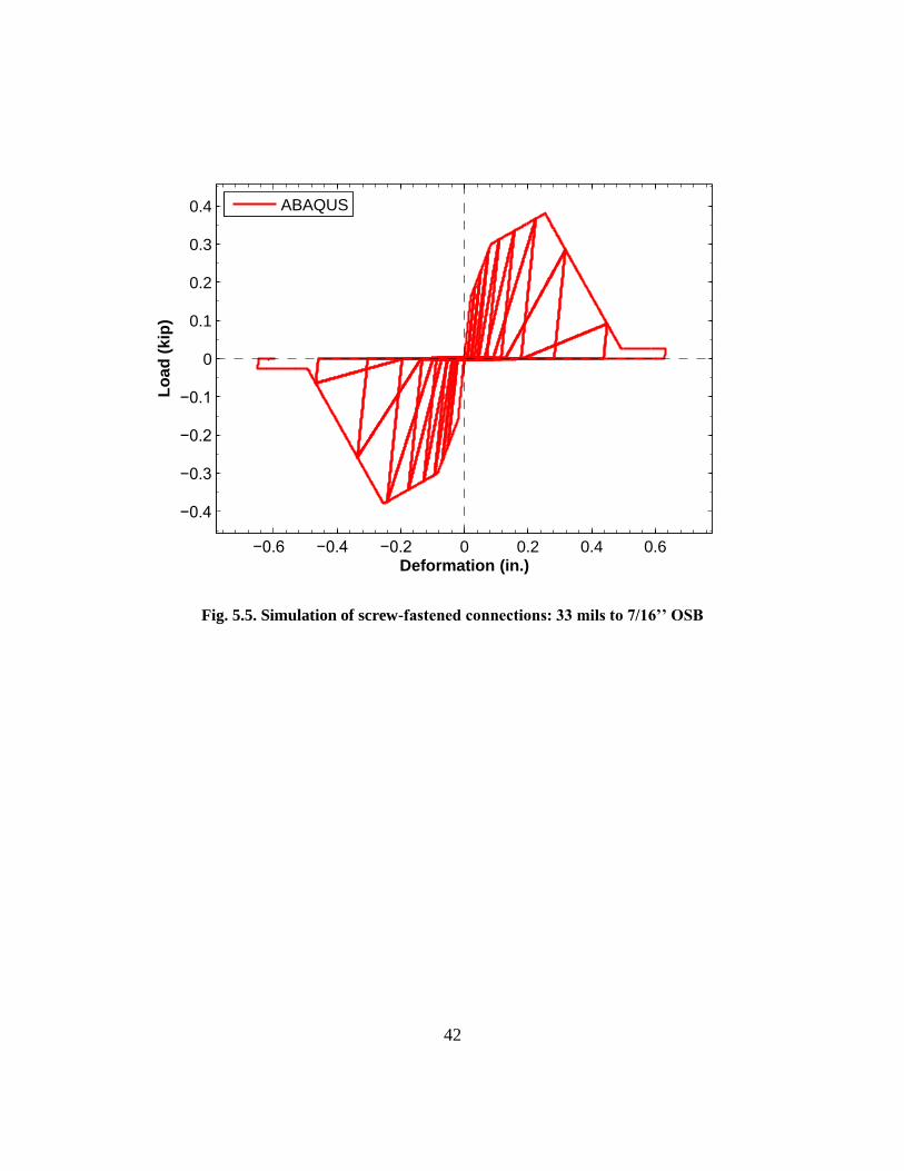
42
Fig. 5.5. Simulation of screw-fastened connections: 33 mils to 7/16’’ OSB
−0.6 −0.4 −0.2 0 0.2 0.4 0.6
−0.4
−0.3
−0.2
−0.1
0
0.1
0.2
0.3
0.4
Deformation (in.)
Lo
ad
(k
ip)
ABAQUS

43
Fig. 5.6. Simulation of screw-fastened connections: 54 mils to 7/16’’ OSB
−0.6 −0.4 −0.2 0 0.2 0.4 0.6
−0.5
−0.4
−0.3
−0.2
−0.1
0
0.1
0.2
0.3
0.4
0.5
Deformation (in.)
Lo
ad
(k
ip)
ABAQUS
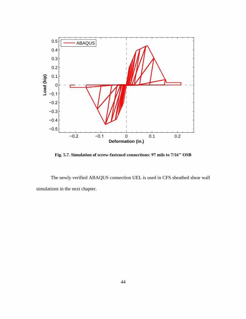
44
Fig. 5.7. Simulation of screw-fastened connections: 97 mils to 7/16’’ OSB
The newly verified ABAQUS connection UEL is used in CFS sheathed shear wall
simulations in the next chapter.
−0.2 −0.1 0 0.1 0.2
−0.5
−0.4
−0.3
−0.2
−0.1
0
0.1
0.2
0.3
0.4
0.5
Deformation (in.)
Lo
ad
(k
ip)
ABAQUS

45
NONLINEAR ANALYSIS OF SHEAR WALLS
6.1 Modeling methodology
This chapter applies the UEL proposed in the previous chapters to high-fidelity
shear wall modeling. Due to the highly nonlinearity of these models, several nonlinear
analysis procedures are discussed and compared herein. Recommendations are made
towards the choice of nonlinear analysis procedures. Simulation results are also compared
to experiments at both system level and fastener level.
6.2 Numerical Model
6.2.1 Model geometry
The 4x 9 shear wall test conducted by Liu et al. (2012a) is simulated in
ABAQUS. The ABAQUS model is modified based on the model created by Ngo (2014)
as shown in Fig. 6.4.

46
Fig. 6.1. Shear wall numerical model geometry
The wall dimension is 4 ft. by 9 ft. Only front sheathing (OSB) is installed and
there is no gypsum sheathing. The rating of the OSB sheathing is APA 24/16 Exposure 1.
The thickness is 7/16 in. The cold-formed steel frames consist of five studs, two tracks
and one ledger. The dimension of studs is 600S162-54 mil (50 ksi). The dimension of
track is 600T150-54 mil (50 ksi). The dimension of ledger is 1200T200-97 mil (50 ksi).
Studs are fastened by #10 Hex head washer back to back on the left and right side of the

47
shear wall to form the chord studs. The tracks are fastened to studs by #10x3/4 in. flat
head screws. The OSB are connected to CFS members by #8x1-15/16 in. flat head.
Fastener spacing is 6 in. There is a seam existing between the two OSB sheathing boards.
However, for simplicity, the seam and fastener connecting steel strap to OSB sheathing
boards are not modeled.
6.2.2 OSB sheathing modeling
The shell element S4R in ABAQUS is used for modeling OSB sheathing boards.
Instead of using the nominal thickness 7/16 in., the actual thickness of 0.4375 in. is used
here. The original model created by Ngo (2014) assumes OSB sheathing as rigid
diagrams by assuming very large modulus of elasticity to OSB material. In order to
consider flexural and shear deformation of OSB sheathing board, the OSB material is
modified based on panel strength from APA Panel Design Specification (APA 2008).
With panel strength, the OSB material flexure and shear modulus is back calculated using
the method adopted by Schafer et al. (2007).
For flexural modulus of elasticity,
3/12 ww tEIE (5.1)
For shear modulus of elasticity,
ww tEtG / (5.2)
OSB is an orthotropic material with differing stiffness in different directions. The
APA Panel Design Specification (APA 2008) considers this by specifying panel strength
in the direction parallel to the strength axis and perpendicular to the strength axis. The

48
panel strength is listed as flexure rigidity and shear rigidity (Table 6.1). By converting
panel rigidity to modulus of elasticity, orthotropic OSB material parameters can be
determined.
Table 6.1. OSB Panel flexural and shear rigidity
Plate bending stiffness
(strength axis)
Plate bending stiffness
(non-strength axis)
Shear rigidity
(through thickness)
E1Iw E2Iw Gv1tv
(lbf-in.2/ft.) (lbf-in.2/ft.) (lbf/in.)
78000 16000 83500
Table 6.2. Converted OSB material modulus of elasticity
Modulus of elasticity
(strength axis)
Modulus of elasticity
(non-strength axis)
Shear modulus
(through thickness)
E1 E2 G12
(ksi) (ksi) (ksi)
1068 219 200
For orthotropic elastic material definition in ABAQUS, modulus of elasticity
parameters and Poisson’s ratio in 3-dimensions are required. The flexural modulus in the
direction normal to the wall plane is not important in this analysis. The flexural modulus
E3 is assumed to be equal to E2 as 219 ksi. Because out-of-plane shear deformation is not
significant in shear wall analysis, the shear modulus corresponding to out-of-plane
direction is taken to be the same as in-plane. Therefore, G13 is set be to 200 ksi. Poisson’s
ratio in all directions are taken as 0.30.

49
6.2.3 CFS members modeling
CFS member modeling (studs, tracks and ledger) is mainly based on the work
done by Ngo (2014). The shell element S4R is utilized for modeling CFS members.
Compared to meshing in the OSB sheathing, finer meshing is used for CFS members to
better capture CFS member behaviors. The steel material is modeled with isotropic
hardening. The choice of plastic or elastic material model has little effect on general
shear wall load-deformation response. However, it affects simulation of CFS members’
torsion and buckling behaviors. With elastic material model, it is found that unreasonably
high stress concentration will occur at the bottom track close to hold-downs and anchor
bolts. Comparison is made between monotonic shear wall analysis with elastic steel
material and one with plastic material in Fig. 6.2 and Fig. 6.3.
Fig. 6.2. Bottom track stress distribution at maximum deformation unde pushover analysis
using elastic steel material

50
Fig. 6.3. Bottom track stress distribution at maximum deformation unde pushover analysis
using plastic steel material
Therefore, it is recommend herein that plastic material model should be used to
model cold-formed steel instead of only using elastic model. The steel elastic properties
are 29,500 ksi (Young’s modulus) and 0.3 (Poisson’s Ratio). The isotropic hardening
parameters are taken from the work by Moen (2009).
Table 6.3. Isotropic hardening parameters
Plastic Strain Stress
ksi
0 55.1
0.003 60.3
0.008 64.9
0.013 68.4
0.023 74
0.033 78.1
0.043 81.3
0.053 83.8
0.063 86.2

51
6.2.4 Fastened connections modeling
There are mainly two types of screw-fastened connections in the shear wall
modeled here, steel-to-steel and steel-to-OSB. Steel-to-steel connections are relatively
“rigid” compared to steel-to-OSB connections. From experiments, rarely were any steel-
to-steel connections found to have failed. There, multi-point constraint pin type (MPC
PIN) is used to simulate steel-to-steel connections.
The UEL proposed in the previous chapters are used for modeling steel-to-OSB
connections. The configuration of these connection is 54 mils to 7/16’’ OSB. Calibrated
Pinching4 model (Peterman and Schafer 2013) is assigned to the UEL so that connection
nonlinearity can be simulated. In order to consider changes in displacement trajectory, the
radial spring model is used for the UEL. The distance between CFS node and OSB node
is set to be 0.2373’’ equal to the distance between CFS and OSB centerlines.
6.3 Pushover Analysis
6.3.1 Influence of analysis procedures
The cold-formed steel frame shear model modeled in this section was already
tested in an experiment. It was found that the shear wall displayed a “brittle” loss of
capacity after reaching its peak load (Fig. 6.4). Such sudden loss of capacity presents
potential challenge for numerical analysis. In some cases, default Newton-Raphson
method in ABAQUS may not be able to capture post-peak response of shear walls. In
order to find a reliable solution procedure, several analysis procedure options are
explored in this section. Their results are compared and discussed.

52
Fig. 6.4. Load-deformation response of shear wall under monotonic loading
The solution techniques applied are Newton-Raphson method, Riks method and
implicit dynamic method. The Newton-Raphson method is the default nonlinear solution
technique in ABAQUS/Standard. It needs the inverse Jacobian matrix in every iteration
to calculate incremental displacement correction, which makes it sometimes numerically
expensive for obtaining solution. It is an effective and accurate analysis procedure for
most of problems. However, for problems tracing scenarios of unstable collapse or post-
buckling, Newton-Raphson method sometimes fails to converge. For these problems,
Riks method can be more reliable, especially for cases with geometric nonlinear collapse.
Riks method iterates by the use of “arc length”. Both displacement and load are unknown
variables to be solved. However, because of the way that Riks method is formulated, it
cannot be used for cyclic analysis.
0 0.5 1 1.5 2 2.5 3 3.5 4 4.50
0.5
1
1.5
2
2.5
3
3.5
4
4.5
5
5.5
Lateral deformation (in.)
Ba
se
sh
ea
r (k
ip)
Experiment

53
The implicit dynamic analysis is also investigated here. Even though implicit
dynamic method stills uses Newton-Raphson method, it considers damping and
acceleration, which can potentially “dissipate” nodal residuals and improve convergence.
The study also demonstrates the UEL’s potential for dynamic analysis. The solution
procedure and time incrementation input are based on the work done by Moen et al.
(2014).
For implicit dynamic analysis, material mass is applied to cold-formed steel and
OSB sheathing based on real material density. The UEL is only assigned with the mass of
a fastener. Rayleigh mass proportional damping with α equal to 0.005 is assigned for
energy dissipation. The loading rate is taken as 0.00004 in./sec to minimize inertia
effects.
The cold-formed steel shear wall model introduced in this chapter is analyzed in
ABAQUS using Newton-Raphson method, Riks method and implicit dynamic analysis.
The shear wall load-deformation curves are shown in the Fig. 6.5. The results from three
different analysis methods are compared. The horizontal axis “Displacement”
corresponds to the drift at the top the shear wall. The vertical axis “Load” corresponds to
the shear wall base shear.

54
Fig. 6.5. Comparison of numerical analysis results using different solution procedures
All of the three analysis methods succeed in capturing post-peak response and
eventually converge. As shown in the Fig. 6.5, the three analysis procedures predict
basically the same peak load and corresponding displacement. Prior to reaching the peak
load, same shear wall response is calculated by the three methods. After reaching the
peak load, there is minimal difference between Newton-Raphson static method and Riks
method. Implicit dynamic method creates slightly different post-peak behaviors with
lower post-peak load immediately after loss of capacity. However, it gradually catches up
with load-deformation paths of the other two methods. This means that the difference
might be caused by acceleration induced by the “sharp” capacity loss since this difference
is eventually dissipated.
0 0.5 1 1.5 2 2.5 3 3.5 4 4.50
0.5
1
1.5
2
2.5
3
3.5
4
4.5
5
5.5
Lateral deformation (in.)
Ba
se
sh
ea
r (k
ip)
Newton−Raphson
Riks
Implicit dynamic

55
From this comparison, it can be shown that Newton-Raphson method is sufficient
for obtaining converged solution for shear wall pushover analysis. But for the case when
Newton-Raphson method fails to converge, Riks method and implicit dynamic method
are available.
6.3.2 Comparison to experiment
Shear wall numerical analysis result is compared to experiment in this section. In
this analysis, radial spring model is selected for simulating screw-fastened connections
and Newton-Raphson method is used for obtaining solution. The steel-to-sheathing
connection Pinching4 parameters are taken from work by Padilla-Llano (2015). These
Pinching4 parameters are shown in Table 6.4 and Table 6.5.
Table 6.4. Steel-to-sheathing Pinching4 backbone parameters
ePd1 ePd2 ePd3 ePd4 ePf1 ePf2 ePf3 ePf4
(in.) (kip.)
0.022 0.124 0.462 0.815 0.192 0.384 0.5 0.049
ePd1 ePd2 ePd3 ePd4 ePf1 ePf2 ePf3 ePf4
(in.) (kip.)
-0.022 -0.124 -0.462 -0.815 -0.192 -0.384 -0.5 -0.049
Table 6.5. Steel-to-sheathing Pinching4 pinching path parameters
rDispP rForceP uForceP rDispN rForceN uForceN
0.42 0.01 0.001 0.42 0.01 0.001
The load-deformation curve of numerical analysis in comparison to experiment
result is shown in Fig. 6.6. The numerical analysis gives very accurate prediction of shear
wall response with slight inelasticity as shown in the first and second “legs” of the curve.

56
However, the shear wall stiffness is underestimated after the shear wall enters severe
softening state as shown in the third “leg”. Regardless of the discrepancy caused by
underestimated stiffness, the predicted post-peak response closely resembles experiment
result.
Fig. 6.6. Comparison of numerical analysis result to experiment
According to experiment data, the response of cold-formed steel frame shear wall
under monotonic loading is controlled by screw-fastened connection failures where
sequential connection failures lead to gradual softening of shear wall response until the
number of failed connections is enough to lead to shear wall failure. Therefore, the input
for connection Pinching4 parameters is critical for obtaining correct simulation. Curves
of connection force with respect to shear wall lateral displacement are created in
0 1 2 3 4 5 60
0.5
1
1.5
2
2.5
3
3.5
4
4.5
5
5.5
Lateral deformation (in.)
Ba
se
sh
ea
r (k
ip)
Experiment
ABAQUS

57
Appendix B. It is found that the initiation and end of three pre-peak legs in these curves
correspond to the three legs in the shear wall load-deformation curve. Thus, the third leg
of connection Pinching4 backbone might be inappropriately chosen, which results into
the difference between experiment results and numerical analysis. More study on single
screw-fastened connection may need to be done in order to obtain closer simulation
result.
The shear wall general deformed shear wall is shown in the Fig. 6.7. The shear
wall as a whole deforms as a deep beam. The cold-formed steel frames is deformed as a
parallelogram with slight bending. Torsion occurs on the middle stud as shown in Fig.
6.9, which is induced by fasteners connecting studs only on one side. The top portion of
the cold-formed steel studs experience relatively high stress. This is possibly due the
restraint created the ledger. The highest stress concentration on cold-formed steel studs
occur at the hold-down areas, where steel around track-to-stud connections have entered
hardening stage (Fig. 6.10). The OSB sheathing is found to rotate relative the cold-
formed steel frame as shown in Fig. 6.11. It experiences much lower stress compared to
cold-formed steel.

58
Fig. 6.7. Shear wall general deformed shape at maximum shear wall displacement
Fig. 6.8. Shear wall top track and ledger area Von Mises stress distribution at maximum
shear wall displacement

59
Fig. 6.9. Torsion of cold-formed steel studs of the shear wall at maximum lateral
deformation
Fig. 6.10. Shear wall bottom track and stud Von Mises stress distribution at maximum
shear wall deformation

60
Fig. 6.11. Rotation of OSB sheathing at the maximum shear wall displacement
In terms of connection behavior, as shown in Fig. 6.12, the connections with
distinctive failures during testing are labeled. Most of connection failures occurred at the
bottom of the shear wall. Almost all track-to-sheathing connections failure by sheathing
pull-through failure. Failures of stud-to-sheathing connections are mostly located at the
stud lower part close to hold-downs. However, more connections failed on the right side
than the left side. This might be explained by the difference between hold-down tension
and compression stiffness.

61
Fig. 6.12. Distribution of failed connections on the shear wall during testing
The Fig. 6.13, Fig. 6.14 and Fig. 6.15 are created showing respectively the
response of the damaged connections on the left side, right side and the bottom. It can be
seen that all connections shown here have been loaded past their strength, which agrees
with experiment observation. However, connections post-peak behaviors are very
different. Many connections on the left and bottom undergoes unloading after reaching
peak load, while the right side connections continue being loaded along the backbone
curves. This phenomenon may be caused by the difference of hold-down stiffness in
compression and tension.
Pull through
Partial Pull
through
Tear out
Damage prior
to testing
Failure not
observed
12
34
56 7 8 9 10 11 12 13
1415
1617
1819
20

62
Fig. 6.13. Load-deformation response of the connections on the left stud bottom
0 0.1 0.2 0.3 0.4 0.5 0.6 0.70
0.1
0.2
0.3
0.4
0.5
Connection Deformation (in.)
Co
nn
ecti
on
fo
rce (
kip
)
Connection 1
Connection 2
Connection 3
Connection 4
Connection 5
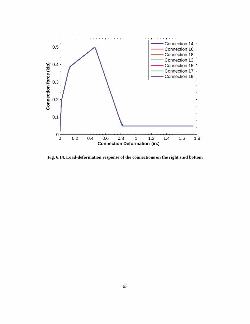
63
Fig. 6.14. Load-deformation response of the connections on the right stud bottom
0 0.2 0.4 0.6 0.8 1 1.2 1.4 1.6 1.80
0.1
0.2
0.3
0.4
0.5
Connection Deformation (in.)
Co
nn
ecti
on
fo
rce (
kip
)
Connection 14
Connection 16
Connection 18
Connection 13
Connection 15
Connection 17
Connection 19

64
Fig. 6.15. Load-deformation response of the connections on the bottom track
6.4 Cyclic Analysis
6.4.1 Fastener-only model study
Compared to pushover analysis, loading and unloading in cyclic analysis adds
more numerical difficulty for convergence. In order to settle on robust modeling
technique, a fastener-only model (Fig. 6.16) is created by modifying original high-fidelity
shear wall discussed in the last section. All the shell elements from the original shear wall
model are discarded leaving only the screw-fastened connections modeled by the UEL.
Rigid diaphragm assumption is assigned to the UEL nodes originally connected to
sheathing shell elements. The other nodes on UEL are pinned to the ground. Cyclic
displacement loading is prescribed on the reference node the top of the rigid diaphragm.
0 0.2 0.4 0.6 0.8 1 1.2 1.4 1.60
0.1
0.2
0.3
0.4
0.5
Connection Deformation (in.)
Co
nn
ecti
on
fo
rce (
kip
)
Connection 6
Connection 7
Connection 8
Connection 10
Connection 11
Connection 12

65
The cyclic loading protocol used in Chapter 5 is applied here with scale factor of 1.5.
Under the cyclic displacement loading, the UEL will experience relative displacement
between its two nodes and then establish resistance. Instead of trying to simplify original
shear wall model, this fastener-only model is intended to mimic the relative displacement
between CFS members and OSB sheathing which is the deformation of the UEL.
It is found that the model quickly divergences after two cycles when some
fasteners enter inelastic state. The reason for this divergence is that change in stiffness of
fasteners causes reestablishment of fastener orientation. Orientation reestablishment
sometimes leads to change in element deformation. For radial spring model, the spring
orientation is updated in each iteration. Combined with nonlinear model, the spring
orientation can oscillate by a large amount and thusly create a cycle of reloading and
unloading in one increment. This possibly contributes to divergence.
In order to solve the divergence issue, the element formulation in the original
UEL is modified. Instead of being a zero length element free to rotate its orientation, the
element orientation is “locked” in the prescribed direction. The direction is determined
based on the orientation that element establish in elastic state. The spring orientation
“locking” only occurs after connection begins yielding corresponding to Pinching4
backbone after the first curve “leg”. This modification is based on the assumption that
certain amount damage on the steel-to-sheathing connection will create a deformation
path on the sheathing. Connection displacement along this deformation path has the
lowest potential energy. Thus, any connection displacement is assumed to follow this
deformation path. In summary, before connection begins yielding, the spring remains

66
radial spring capable of rotating its orientation. After the connection begins yielding, the
spring “locks” its orientation and changes into modified radial spring. Still only spring is
used in order to avoid overestimation of strength and stiffness. It is assumed that screw
during testing is relatively “locked” along the sheathing damaged trajectory.
Fig. 6.16. Fastener-only model
With this modification, the fastener-models can converge. The fastener-only
model response is shown in Fig. 6.17. It can be seen that the fastener-model result shows
clear resemblance to fastener hysteretic response. Both peak load and pinching are
simulated in this model.
cyclic loading
UEL
pinned node
rigid diaphragm
node

67
Fig. 6.17. Hysteretic response of fastener-only model
−1.5 −1 −0.5 0 0.5 1 1.5−15
−10
−5
0
5
10
15
Displacement (in.)
Fo
rce (
kip
)
ABAQUS

68
Fig. 6.18. Hysteretic response of one fastener in fastener-only model
6.4.2 High-fidelity model
With the convergent solution obtained in the fastener-only model, the high-
fidelity shear wall model analyzed monotonically is assigned with cyclic displacement
loading. Still, the modified UEL is used for analysis. Newton-Raphson method is used for
obtaining the solution.
Deformation (in.)
Lo
ad
(k
ip)
ABAQUS0.5
0.4
0.3
0.2
0.1
0
-0.1
-0.2
-0.3
-0.4
-0.5
0 0.2 0.4 0.6-0.2-0.4-0.6

69
Fig. 6.19. Cyclic response of high-fidelity shear wall model
Shear wall cyclic response shows a nonlinear backbone and pinching. It can be
seen that the shear wall cyclic response highly resembles the hysteretic behavior of
individual fasteners. Because the shear wall hysteretic response is actually the
combination of all individual fastener responses, the shear wall load-deformation curve is
smoother than fastener. The response of one of the connections on the top track is shown
in the Fig. 6.20.
−6 −4 −2 0 2 4 6
−5
−4
−3
−2
−1
0
1
2
3
4
5
Lateral deformation (in.)
Ba
se
sh
ea
r (k
ip)
ABAQUS
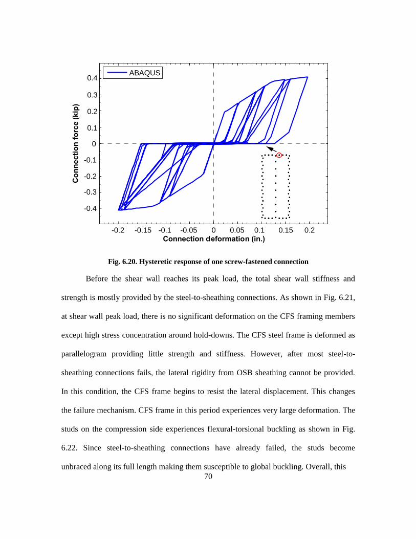
70
Fig. 6.20. Hysteretic response of one screw-fastened connection
Before the shear wall reaches its peak load, the total shear wall stiffness and
strength is mostly provided by the steel-to-sheathing connections. As shown in Fig. 6.21,
at shear wall peak load, there is no significant deformation on the CFS framing members
except high stress concentration around hold-downs. The CFS steel frame is deformed as
parallelogram providing little strength and stiffness. However, after most steel-to-
sheathing connections fails, the lateral rigidity from OSB sheathing cannot be provided.
In this condition, the CFS frame begins to resist the lateral displacement. This changes
the failure mechanism. CFS frame in this period experiences very large deformation. The
studs on the compression side experiences flexural-torsional buckling as shown in Fig.
6.22. Since steel-to-sheathing connections have already failed, the studs become
unbraced along its full length making them susceptible to global buckling. Overall, this
Connection deformation (in.)
Co
nn
ecti
on
fo
rce (
kip
)ABAQUS
-0.2 -0.15 -0.1 -0.05 0 0.05 0.1 0.15 0.2
-0.4
-0.3
-0.2
-0.1
0
0.1
0.2
0.3
0.4

71
Fig. 6.21. Deformed shape of the shear wall at the maximum load
Fig. 6.22. Deformed shape of the shear wall at the maximum displacement

72
CONCLUSIONS AND FUTURE WORK
The objective is of this thesis is to provide an approach for simulating screw-
fastened connections in ABAQUS and make it applicable to shear wall numerical
analysis. The difficulty lies in the fact that there is no suitable material or element type
for simulating nonlinearity observed in connection tests. This objective is accomplished
by creating a user element subroutine (UEL) for ABAQUS/Standard. This user element
converts Pinching4 model from OpenSees to ABAQUS to provide ABAQUS with a
suitable material type and to make use of latest research on screw-fastened connections.
To represent the deformation trajectory of shear wall connections under loading, the
radial spring model is proposed. However, to provide users with modeling flexibility,
three other prevalent spring models are also included in the UEL here.
Pushover and cyclic of cold-formed steel framed shear walls are performed using the
UEL proposed herein. Pushover analysis results are compared to experiments, which
shows the potential of the UEL to be applied for high-fidelity modeling. Comparison are
made to study the influence of solution procedures, spring model selection and
connection input on predicted shear wall behaviors.
Overall, this research provides future researchers with numerical analysis tools to study
cold-formed steel framed structures. Not only can cold-formed steel framed shear walls
be studied numerically, studies can be also extended to any cold-formed steel subsystems
with screw-fastened connections such as diaphragms or cold-formed steel built-up
columns.

73
Still, future work is needed. Questions need to be answered whether connection
deformation trajectory changes or keeps being relatively “locked” after damage occurs.
To aid this effort, the real connection deformation trajectory in shear wall experiment
might need to be monitored. Based on current UEL, with Pinching4 model successfully
implemented in ABAQUS, only element formulation section needs to be modified.
Besides, the monotonic and cyclic of cold-formed steel framed shear walls remains a
preliminary attempt to study this important subsystem by using commercial finite
element software. More in-depth work can be accomplished by using the proposed
ABAQUS UEL herein, which hopefully can advance our understanding of cold-formed
steel frame structures.

74
REFERENCES
ABAQUS (2013). "Abaqus User Subroutines Reference Guide." Dassault Systèmes.
ABAQUS (2013). "ABAQUS/Standard Version 6.13." Dassault Systèmes.
APA (2008). "Panel design specification."
Bian, G., Buonopane, S. G., Ngo, H. H., and Schafer, B. W. (2014). "Fastener-based
computational models with application to cold-formed steel shear walls." 22nd
International Specialty Conference on Cold-Formed Steel StructuresSt. Louis,
Missouri, USA.
Buonopane, S., Tun, T., and Schafer, B. "Fastener-based computational models for
prediction of seismic behavior of CFS shear walls." Proc., Proceedings of the
10th National Conference in Earthquake Engineering.
De Borst, R., Crisfield, M. A., Remmers, J. J., and Verhoosel, C. V. (2012). Nonlinear
finite element analysis of solids and structures, John Wiley & Sons.
Dowell, R. K., Seible, F., and Wilson, E. L. (1998). "Pivot hysteresis model for
reinforced concrete members." ACI Structural Journal, 95(5).
Folz, B., and Filiatrault, A. (2000). "CASHEW—Version 1.0: A computer program for
cyclic analysis of wood shear walls." Richmond, California.
Folz, B., and Filiatrault, A. (2001). "Cyclic analysis of wood shear walls." Journal of
Structural Engineering, 127(4), 433-441.
Foschi, R. O. (1974). "Load-slip characteristics of nails." Wood Sci, 7(1), 69-76.

75
Ibarra, L. F., Medina, R. A., and Krawinkler, H. (2005). "Hysteretic models that
incorporate strength and stiffness deterioration." Earthquake engineering &
structural dynamics, 34(12), 1489-1511.
Judd, J. P. (2005). "Analytical modeling of wood-frame shear walls and diaphragms."
Judd, J. P., and Fonseca, F. S. (2005). "Analytical model for sheathing-to-framing
connections in wood shear walls and diaphragms." Journal of Structural
Engineering, 131(2), 345-352.
Leng, J., Schafer, B., and Buonopane, S. "Modeling the seismic response of cold-formed
steel framed buildings: model development for the CFS-NEES building." Proc.,
Proceedings of the Annual Stability Conference-Structural Stability Research
Council, St. Louis, Missouri.
Liu, P., Peterman, K. D., and Schafer, B. W. (2012). "Test Report on Cold-Formed Steel
Shear Walls." CFS-NEES – RR03.
Liu, P., Peterman, K. D., and Schafer, B. W. (2012a). "Test report on cold-formed steel
shear walls." Research Report.
Lowes, L. N., Mitra, N., and Altoontash, A. (2003). A beam-column joint model for
simulating the earthquake response of reinforced concrete frames, Pacific
Earthquake Engineering Research Center, College of Engineering, University of
California.
Mazzoni, S., McKenna, F., Scott, M. H., and Fenves, G. L. (2006). "OpenSees command
language manual." Pacific Earthquake Engineering Research (PEER) Center.

76
Moen, C. D. (2009). Direct strength design of cold-formed steel members with
perforations, ProQuest.
Moen, C. D., Padilla-Llano, D. A., Corner, S., and Ding, C. (2014). "Towards Load-
Deformation Models for Screw-Fastened Cold-
Formed Steel-to-Steel Shear Connections." 22nd International Specialty Conference on
Cold-Formed Steel StructuresSt. Louis, Missouri.
Ngo, H. H. (2014). "Numerical and experimental studies Of wood sheathed cold-formed
steel framed shear walls." Master of Science in Engineering, Johns Hopkins
University, Baltimore, Maryland.
Padilla-Llano, D. A. (2015). "A Framework for Cyclic Simulation of Thin-Walled Cold-
Formed Steel Members in Structural Systems."
Padilla-Llano, D. A., Moen, C. D., and Eatherton, M. R. (2014). "Cyclic axial response
and energy dissipation of cold-formed steel framing members." Thin-Walled
Structures, 78, 95-107.
Pang, W., and Hassanzadeh Shirazi, S. M. (2012). "Corotational model for cyclic analysis
of light-frame wood shear walls and diaphragms." Journal of Structural
Engineering, 139(8), 1303-1317.
Peterman, K., and Schafer, B. (2013). "Hysteretic shear response of fasteners connecting
sheathing to cold-formed steel studs." Research Report, CFS-NEES, RR04.
Peterman, K., Stehman, M., Buonopane, S., Nakata, N., Madsen, R., and Schafer, B.
(2014). "SEISMIC PERFORMANCE OF FULL-SCALE COLD-FORMED
STEEL BUILDINGS.", Tenth U.S. National Conference on Earthquake
Engineering, Anchorage, Alaska.

77
Ramm, E. (1981). Strategies for tracing the nonlinear response near limit points,
Springer.
Schafer, B. W., Sangree, R., and Guan, Y. (2007). "Experiments on rotational restraint of
sheathing." Report for American Iron and Steel Institute-Committee on Framing
Standards. Baltimore, Maryland.
Tun, T. H. (2014). "Fastener-Based Computational Models Of Cold-Formed Steel Shear
Walls."
Xu, J., and Dolan, J. D. (2009). "Development of nailed wood joint element in
ABAQUS." Journal of structural engineering, 135(8), 968-976.

78
APPENDIX A ANALYSIS CASES OF PINCHING4 MODEL
VERIFICATION
A.1 Backbone and Pinching Paths Verification
Six verification cases are analyzed in ABAQUS by UEL and compared to OpenSees.
Their parameter input are listed in the following tables.
Table A.1. Positive Pinching4 backbone parameters of verification cases
Model ePd1 ePd2 ePd3 ePd4 ePf1 ePf2 ePf3 ePf4
(in.) (kip.)
c33-o6-1 0.018 0.069 0.241 0.540 0.158 0.298 0.371 0.021
c33-o12-1 0.021 0.050 0.207 0.446 0.142 0.211 0.327 -0.013
c54-o6-1 0.016 0.064 0.241 0.344 0.160 0.286 0.409 0.022
c54-o12-1 0.019 0.077 0.230 0.427 0.207 0.381 0.475 0.054
c97-o6-1 0.011 0.041 0.084 0.229 0.164 0.313 0.359 0.015
c97-o12-1 0.011 0.036 0.067 0.121 0.218 0.405 0.475 0.049
Table A.2. Negative Pinching4 backbone parameters of verification cases
Model eNd1 eNd2 eNd3 eNd4 eNf1 eNf2 eNf3 eNf4
(in.) (kip.)
c33-o6-1 -0.024 -0.077 -0.267 -0.494 -0.211 -0.313 -0.427 -0.052
c33-o12-1 -0.019 -0.085 -0.266 -0.447 -0.123 -0.248 -0.324 -0.018
c54-o6-1 -0.025 -0.097 -0.223 -0.402 -0.234 -0.374 -0.475 -0.056
c54-o12-1 -0.019 -0.114 -0.258 -0.445 -0.204 -0.361 -0.466 -0.065
c97-o6-1 -0.012 -0.049 -0.112 -0.234 -0.194 -0.361 -0.380 -0.004
c97-o12-1 -0.010 -0.040 -0.088 -0.132 -0.197 -0.432 -0.494 -0.038

79
Table A.3. Pinching path parameters of verification cases
Model rDispP rForceP uForceP rDispN rForceN uForceN
c33-o6-1 0.481 0.011 0.001 0.333 0.011 0.001
c33-o12-1 0.506 0.016 0.001 -0.123 0.012 0.001
c54-o6-1 0.498 0.012 0.001 0.104 0.011 0.001
c54-o12-1 0.488 0.011 0.001 0.403 0.011 0.001
c97-o6-1 0.500 0.013 0.001 0.164 0.011 0.001
c97-o12-1 0.510 0.010 0.001 -0.198 0.014 0.001

80
Fig. A.1. Verification case c33o6_1 (a) Load-deformation (b) Energy-cycle
−0.8 −0.6 −0.4 −0.2 0 0.2 0.4 0.6 0.8−0.5
−0.4
−0.3
−0.2
−0.1
0
0.1
0.2
0.3
0.4
0.5
Deformation (in.)
Lo
ad
(k
ip)
Opensees
ABAQUS
0 2 4 6 8 10 12 14 16 18−0.2
0
0.2
0.4
0.6
0.8
1
Number of Cycles
Ei /
Eto
tal
Opensees
ABAQUS

81
Fig. A.2. Verification case c33o12_1 (a) Load-deformation (b) Energy-cycle
−0.6 −0.4 −0.2 0 0.2 0.4 0.6
−0.3
−0.2
−0.1
0
0.1
0.2
0.3
Deformation (in.)
Lo
ad
(k
ip)
Opensees
ABAQUS
0 2 4 6 8 10 12 14 16 18−0.2
0
0.2
0.4
0.6
0.8
1
Number of Cycles
Ei /
Eto
tal
Opensees
ABAQUS

82
Fig. A.3. Verification case c54o6_1 (a) Load-deformation (b) Energy-cycle
−0.4 −0.2 0 0.2 0.4 0.6
−0.5
−0.4
−0.3
−0.2
−0.1
0
0.1
0.2
0.3
0.4
0.5
Deformation (in.)
Lo
ad
(k
ip)
Opensees
ABAQUS
0 2 4 6 8 10 12 14 16 18−0.2
0
0.2
0.4
0.6
0.8
1
Number of Cycles
Ei /
Eto
tal
Opensees
ABAQUS

83
Fig. A.4. Verification case c54o12_1 (a) Load-deformation (b) Energy-cycle
−0.6 −0.4 −0.2 0 0.2 0.4 0.6
−0.5
−0.4
−0.3
−0.2
−0.1
0
0.1
0.2
0.3
0.4
0.5
Deformation (in.)
Lo
ad
(k
ip)
Opensees
ABAQUS
0 2 4 6 8 10 12 14 16 18−0.2
0
0.2
0.4
0.6
0.8
1
Number of Cycles
Ei /
Eto
tal
Opensees
ABAQUS

84
Fig. A.5. Verification case c97o6_1 (a) Load-deformation (b) Energy-cycle
−0.3 −0.2 −0.1 0 0.1 0.2 0.3
−0.4
−0.3
−0.2
−0.1
0
0.1
0.2
0.3
0.4
Deformation (in.)
Lo
ad
(k
ip)
Opensees
ABAQUS
0 2 4 6 8 10 12 14 16 18−0.2
0
0.2
0.4
0.6
0.8
1
Number of Cycles
Ei /
Eto
tal
Opensees
ABAQUS

85
A.2 Degradation Verification
Three verification cases are analyzed in ABAQUS studying respectively unloading
stiffness degradation, reloading stiffness degradation and strength degradation. Pinching4
parameters of typical 54 mils to 7/16’’ OSB connections are used. ABAQUS results are
compared to OpenSees. The Pinching4 parameter input are listed in the following tables.
Table A.4. Backbone parameter of degradation verification cases
ePd1 ePd2 ePd3 ePd4 eNd1 eNd2 eNd3 eNd4
(in.) (in.)
0.020 0.078 0.246 0.414 -0.020 -0.078 -0.246 -0.414
ePf1 ePf2 ePf3 ePf4 eNf1 eNf2 eNf3 eNf4
(kip.) (kip.)
0.220 0.350 0.460 0.049 -0.220 -0.350 -0.460 -0.049
Table A.5. Degradation parameters of degradation verification cases
Degradation 1 2 3 4 lim
Unloading stiffness 0.250 0.850 0.650 0.120 1000.000
Reloading stiffness 2.740 0.240 1.720 0.980 1000.000
Strength 0.160 1.170 0.530 0.460 1000.000

86
Fig. A.6. Unloading stiffness verification case: (a) Load-deformation (b) Cycle-energy
−0.6 −0.4 −0.2 0 0.2 0.4 0.6
−0.5
−0.4
−0.3
−0.2
−0.1
0
0.1
0.2
0.3
0.4
0.5
Deformation (in.)
Lo
ad
(k
ip)
Opensees
ABAQUS
0 2 4 6 8 10 12 14 16 18−0.2
0
0.2
0.4
0.6
0.8
1
Number of Cycles
Ei /
Eto
tal
Opensees
ABAQUS

87
Fig. A.7. Reloading stiffness verification case: (a) Load-deformation (b) Cycle-energy
−0.6 −0.4 −0.2 0 0.2 0.4 0.6
−0.5
−0.4
−0.3
−0.2
−0.1
0
0.1
0.2
0.3
0.4
0.5
Deformation (in.)
Lo
ad
(k
ip)
Opensees
ABAQUS
0 2 4 6 8 10 12 14 16 18−0.2
0
0.2
0.4
0.6
0.8
1
Number of Cycles
Ei /
Eto
tal
Opensees
ABAQUS
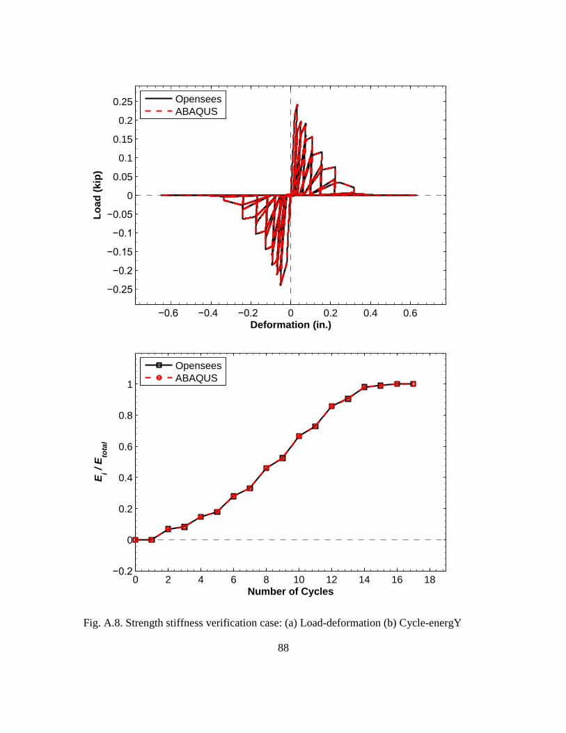
88
Fig. A.8. Strength stiffness verification case: (a) Load-deformation (b) Cycle-energY
−0.6 −0.4 −0.2 0 0.2 0.4 0.6
−0.25
−0.2
−0.15
−0.1
−0.05
0
0.05
0.1
0.15
0.2
0.25
Deformation (in.)
Lo
ad
(k
ip)
Opensees
ABAQUS
0 2 4 6 8 10 12 14 16 18−0.2
0
0.2
0.4
0.6
0.8
1
Number of Cycles
Ei /
Eto
tal
Opensees
ABAQUS

89
APPENDIX B CONNECTION RESPONSE IN PUSHOVER
ANALYSIS
The following figures shows screw-fastened connection force with respect to shear wall
lateral displacement. Only those that are reported to have failed during shear experiment
are shown here. The Fig. B.1, Fig. B.2 and Fig. B.3 shows failed connections at different
locations, namely left stud bottom, right stud bottom and bottom track. The dashed lines
in the these figures labels the specific shear wall lateral displacement corresponding to
the initiation and end of shear wall load-deformation curve “legs”.
Fig. B.1. Force of left stud bottom connections a shear wall lateral displacement
0 1 2 3 4 5 60
0.1
0.2
0.3
0.4
0.5
Shear Wall Lateral Displacement (in.)
Co
nn
ecti
on
fo
rce (
kip
)
Connection 1
Connection 2
Connection 3
Connection 4
Connection 5

90
Fig. B.2. Force of right stud bottom connections against shear wall lateral displacement
0 1 2 3 4 5 60
0.1
0.2
0.3
0.4
0.5
Shear Wall Lateral Displacement (in.)
Co
nn
ecti
on
fo
rce (
kip
)
Connection 14
Connection 16
Connection 18
Connection 13
Connection 15
Connection 17
Connection 19

91
Fig. B.3. Force of bottom track connections against shear wall lateral displacement
0 1 2 3 4 5 60
0.1
0.2
0.3
0.4
0.5
Shear Wall Lateral Displacement (in.)
Co
nn
ecti
on
fo
rce (
kip
)
Connection 6
Connection 7
Connection 8
Connection 10
Connection 11
Connection 12

92
APPENDIX C USER ELEMENT SUBROUTINE IMPLICIT CODE
(UEL)
C C *********************************************************************************************************** C ABAQUS USER ELEMENT SUBROUTINE (UEL) C --- FOR FASTENER-BASED SHEAR WALL/DIAPHRAGM ANALYSIS --- C ----------------------------------------------------------------------- C AUTHOR: Chu Ding ([email protected]) C ADVISOR: Dr. Cristopher D. Moen ([email protected]) C RESEARCH GROUP: http://www.moen.cee.vt.edu/ C *********************************************************************************************************** C SUBROUTINE UEL(RHS,AMATRX,SVARS,ENERGY,NDOFEL,NRHS,NSVARS, + PROPS,NPROPS,COORDS,MCRD,NNODE,U,DU,V,A,JTYPE,TIME,DTIME, + KSTEP,KINC,JELEM,PARAMS,NDLOAD,JDLTYP,ADLMAG,PREDEF, + NPREDF,LFLAGS,MLVARX,DDLMAG,MDLOAD,PNEWDT,JPROPS,NJPROP, + PERIOD) C C C ***************************************************************** C C INCLUDE 'ABA_PARAM.INC' C PARAMETER (TOL = 1.D-128, ZERO = 0.D0, PONE = 0.1D0, HALF = 0.5D0, + ONE = 1.D0, TWO = 2.D0) C C DIMENSION RHS(MLVARX,*),AMATRX(NDOFEL,NDOFEL),PROPS(*), 1 SVARS(*),ENERGY(8),COORDS(MCRD,NNODE),U(NDOFEL), 2 DU(MLVARX,*),V(NDOFEL),A(NDOFEL),TIME(2),PARAMS(*), 3 JDLTYP(MDLOAD,*),ADLMAG(MDLOAD,*),DDLMAG(MDLOAD,*), 4 PREDEF(2,NPREDF,NNODE),LFLAGS(*),JPROPS(*) C DIMENSION SRESID(4) DIMENSION SPR_AMATRX(4,4), SPR_SRESID(4) C DOUBLE PRECISION SPR_LEN, SPR_DISP

93
DOUBLE PRECISION SPR_COS_X, SPR_COS_Y DOUBLE PRECISION SPR_DISP_X, SPR_DISP_Y DOUBLE PRECISION SPR_K, SPR_F DOUBLE PRECISION SPR_SGN DOUBLE PRECISION SPR_K_X, SPR_K_Y DOUBLE PRECISION SPR_F_X, SPR_F_Y DOUBLE PRECISION SPR_DISP_U, SPR_DISP_V DOUBLE PRECISION SPR_K_U, SPR_K_V DOUBLE PRECISION SPR_F_U, SPR_F_V C DOUBLE PRECISION SPR_K_SEC, SPR_K_SEC_X, SPR_K_SEC_Y DOUBLE PRECISION SPR_K_SEC_U, SPR_K_SEC_V C DOUBLE PRECISION SPR_ORIENT_1, SPR_ORIENT_2 C DOUBLE PRECISION SPR_DISP1, SPR_DISP2, SPR_F1, SPR_F2, SPR_ENERGY C DOUBLE PRECISION SPR_YD C INTEGER I_SPR_NUM INTEGER KPNT, KSEC, KORIENT C CHARACTER FILENAME*200 CHARACTER*(*) FILEPATH C C C -------------- Choose spring data output path -------------- C ********************************************************************************************** PARAMETER (FILEPATH = 'E:\Onedrive\VT_RESEARCH\UEL work\uel_upgrade\add all springs\modified radial spring\check\') C ********************************************************************************************** C C C -------------- Select your spring type -------------- C ********************************************************************************************** C * 1: Radial spring, 2: Coupled spring pair, 3: Uncoupled spring pair, 4: Oriented spring pair C * 5: Modified radial spring KPNT = 5 C * 0: Tangent stiffness, 1: Secant stiffness KSEC = 0 C * 0: Default deformation quadrants, 1: Displacement-based deformation quadrants KORIENT = 1 C * 0: Forbid spring data output, 1: Permit spring data output KOUTPUT = 1 C ********************************************************************************************** C C

94
C Specify fastener mass AM = 4.5D-5 C C Initialize vector variables DO K1 = 1, NDOFEL SRESID(K1) = ZERO SPR_SRESID(K1) = ZERO DO KRHS = 1, NRHS RHS(K1,KRHS) = ZERO END DO DO K2 = 1, NDOFEL AMATRX(K1, K2) = ZERO SPR_AMATRX(K1,K2) = ZERO END DO END DO C C Initialize scalar variables SPR_DISP_X = ZERO SPR_DISP_Y = ZERO SPR_K_X = ZERO SPR_K_Y = ZERO SPR_F_X = ZERO SPR_F_Y = ZERO C C C **************** Generate spring geometry info. **************** IF (KPNT .EQ. 1) THEN C * Radial-spring model CALL SGEOM(U,COORDS,SPR_LEN,SPR_DISP,SPR_COS_X,SPR_COS_Y,SPR_DISP_X,SPR_DISP_Y,PROPS,SVARS) ELSE IF (KPNT. EQ. 2) THEN C * Coupled-spring model CALL SGEOM_CUP(U,SPR_DISP,SPR_COS_X,SPR_COS_Y,SPR_DISP_X,SPR_DISP_Y) ELSE IF (KPNT .EQ. 4) THEN C * Oriented spring pair CALL SGEOM_ORN(U, SPR_DISP_X, SPR_DISP_Y, SPR_COS_X, SPR_COS_Y, SPR_DISP_U, SPR_DISP_V, SVARS) ELSE IF (KPNT .EQ. 5) THEN IF (SVARS(180) .EQ. ZERO) THEN CALL SGEOM(U,COORDS,SPR_LEN,SPR_DISP,SPR_COS_X,SPR_COS_Y,SPR_DISP_X,SPR_DISP_Y,PROPS,SVARS) ELSE CALL SGEOM_MDRD(U,COORDS,SPR_LEN,SPR_DISP,SPR_COS_X,SPR_COS_Y,SPR_DISP_X,SPR_DISP_Y,PROPS,SVARS) END IF

95
ELSE C * 2-spring model CALL SGEOM(U,COORDS,SPR_LEN,SPR_DISP,SPR_COS_X,SPR_COS_Y,SPR_DISP_X,SPR_DISP_Y,PROPS,SVARS) END IF C C C **************** Record connection yielding **************** IF (KPNT .EQ. 1 .OR. KPNT .EQ. 2 .OR. KPNT. EQ. 5) THEN IF (SVARS(180) .EQ. ZERO) THEN IF (DABS(SPR_DISP) .GE. DABS(PROPS(1))) THEN SPR_YD = ONE SVARS(180) = ONE SVARS(181) = SPR_COS_X SVARS(182) = SPR_COS_Y ELSE SPR_YD = ZERO SVARS(180) = ZERO END IF END IF END IF C C C **************** Save spring original orientation **************** * * Set up spring positive/negative deformation rule C * Only applicable to radial spring/coupled spring/modified radial spring IF (KPNT .EQ. 1 .OR. KPNT .EQ. 2 .OR. KPNT .EQ. 5) THEN C * Deformation quadrant based on initial displacement IF (KORIENT .EQ. 1) THEN IF (SVARS(128) .NE. ONE) THEN C * Use default deformation quadrant when deformation is "zero" IF (DABS(SPR_DISP) .LE. TWO * TOL) THEN SVARS(129) = 1.D0/DSQRT(2.D0) SVARS(130) = 1.D0/DSQRT(2.D0) ELSE C * Now use displacement-based quadrant C * Save spring orientation SVARS(129) = SPR_COS_X SVARS(130) = SPR_COS_Y C * Keep spring orientation quadrant fixed now SVARS(128) = SVARS(128) + ONE END IF END IF C * Retrieve spring orientation SPR_ORIENT_1 = SVARS(129) SPR_ORIENT_2 = SVARS(130) C * Default deformation quadrant ELSE

96
SPR_ORIENT_1 = 1.D0/DSQRT(2.D0) SPR_ORIENT_2 = 1.D0/DSQRT(2.D0) END IF END IF C C C **************** Adjust spring deformation sign **************** C * Only applicable to radial spring/coupled spring model IF (KPNT .EQ. 1 .OR. KPNT .EQ. 2 .OR. (KPNT .EQ. 5 .AND. SVARS(180) .EQ. ZERO)) THEN SPR_SGN = ONE C * For the case of "real compression" IF (SPR_DISP .LT. ZERO) THEN SPR_SGN = ONE C * For the case of "fake compression" determined by deformation quadrants ELSE IF (SPR_DISP_X .NE. ZERO .AND. SPR_DISP_Y .NE. ZERO) THEN IF (SPR_ORIENT_1 * SPR_DISP_X + SPR_ORIENT_2 * SPR_DISP_Y .LT. ZERO) THEN SPR_SGN = -ONE END IF END IF C * Spring deformation is assinged with positive or negative sign SPR_DISP = SPR_SGN * SPR_DISP ELSE SPR_SGN = ONE END IF !C C C **************** Get spring stiffness and force from nonlinear model **************** C * Apply to radial spring, coupled two-spring, modified radial spring * IF (KPNT .EQ. 1 .OR. KPNT. EQ. 2 .OR. KPNT .EQ. 5) THEN C Use tangent stiffness definition I_SPR_NUM = 1 CALL PINCHING4(PROPS,SVARS,SPR_DISP,SPR_K,SPR_F,KINC,I_SPR_NUM) C C Use secant stiffness definition IF (KSEC .EQ. 1 .AND. DABS(SPR_DISP) .GE. TOL) THEN SPR_K_SEC = SPR_F / SPR_DISP SPR_K = SPR_K_SEC END IF C * Apply to oriented spring pair * ELSE IF (KPNT .EQ. 4) THEN C IF (KINC .EQ. 0 .OR. KINC .EQ. 1) THEN SPR_DISP_U = SPR_DISP_X SPR_DISP_V = SPR_DISP_Y END IF C

97
I_SPR_NUM = 1 CALL PINCHING4(PROPS,SVARS,SPR_DISP_U,SPR_K_U,SPR_F_U,KINC,I_SPR_NUM) C I_SPR_NUM = 2 CALL PINCHING4(PROPS,SVARS,SPR_DISP_V,SPR_K_V,SPR_F_V,KINC,I_SPR_NUM) C C Use secant stiffness definition IF (KSEC .EQ. 1. AND. DABS(SPR_DISP_U) .GE. TOL .AND. DABS(SPR_DISP_V) .GE. TOL) THEN SPR_K_SEC_U = SPR_F_U / SPR_DISP_U SPR_K_SEC_V = SPR_F_V / SPR_DISP_V SPR_K_U = SPR_K_SEC_U SPR_K_V = SPR_K_SEC_V END IF C IF (KINC .EQ. 0 .OR. KINC .EQ. 1) THEN SPR_K_X = SPR_K_U SPR_F_X = SPR_F_U SPR_K_Y = SPR_K_V SPR_F_Y = SPR_F_V END IF C C * Apply two-spring model ELSE C Use tangent stiffness definition I_SPR_NUM = 1 CALL PINCHING4(PROPS,SVARS,SPR_DISP_X,SPR_K_X,SPR_F_X,KINC,I_SPR_NUM) C I_SPR_NUM = 2 CALL PINCHING4(PROPS,SVARS,SPR_DISP_Y,SPR_K_Y,SPR_F_Y,KINC,I_SPR_NUM) C C Use secant stiffness definition IF (KSEC .EQ. 1. AND. DABS(SPR_DISP_X) .GE. TOL .AND. DABS(SPR_DISP_Y) .GE. TOL) THEN SPR_K_SEC_X = SPR_F_X / SPR_DISP_X SPR_K_SEC_Y = SPR_F_Y / SPR_DISP_Y SPR_K_X = SPR_K_SEC_X SPR_K_Y = SPR_K_SEC_Y END IF END IF C C C **************** Generate stiffness matrix and residual force vector **************** C * Radial spring model IF (KPNT .EQ. 1 .OR. KPNT .EQ. 5) THEN

98
CALL SAMATRX(SPR_AMATRX, SPR_K, SPR_F, SPR_LEN, SPR_COS_X, SPR_COS_Y, SPR_SGN) CALL SNFORCE(SPR_F, SPR_COS_X, SPR_COS_Y, SPR_SRESID, SPR_SGN) C * Coupled spring model ELSE IF (KPNT .EQ. 2) THEN CALL SAMATRX_CUP(SPR_AMATRX, SPR_K) CALL SNFORCE(SPR_F, SPR_COS_X, SPR_COS_Y, SPR_SRESID, SPR_SGN) C * Oriented spring pair model ELSE IF (KPNT .EQ. 4) THEN IF (KINC. EQ. 1 .OR. KINC .EQ. 0) THEN CALL SAMATRX_2(SPR_AMATRX, SPR_K_X, SPR_K_Y) CALL SFORCE_2(SPR_SRESID, SPR_F_X, SPR_F_Y) ELSE CALL SAMATRX_ORNT(SPR_AMATRX, SPR_K_U, SPR_K_V, SVARS) CALL SNFORCE_ORNT(SPR_F_U, SPR_F_V, SVARS, SPR_SRESID, SPR_F_X, SPR_F_Y) END IF C * Uncoupled 2-spring model ELSE CALL SAMATRX_2(SPR_AMATRX, SPR_K_X, SPR_K_Y) CALL SFORCE_2(SPR_SRESID, SPR_F_X, SPR_F_Y) END IF C C C **************** Update energy **************** IF (KPNT .EQ. 1 .OR. KPNT .EQ. 2 .OR. KPNT .EQ. 5) THEN SVARS(141) = SVARS(142) ! Deformation for last increment SVARS(142) = SPR_DISP ! Deformation at current increment SVARS(143) = SVARS(144) ! Spring force from last increment SVARS(144) = SPR_F ! Spring force at current increment C SPR_DISP1 = SVARS(141) SPR_DISP2 = SVARS(142) SPR_F1 = SVARS(143) SPR_F2 = SVARS(144) SPR_ENERGY = HALF * (SPR_F2 + SPR_F1) * (SPR_DISP2 - SPR_DISP1) SVARS(145) = SVARS(145) + SPR_ENERGY ELSE SVARS(141) = SVARS(142) SVARS(142) = SPR_DISP_X SVARS(143) = SVARS(144) SVARS(144) = SPR_DISP_Y SVARS(146) = SVARS(147) SVARS(147) = SPR_F_X SVARS(148) = SVARS(149) SVARS(149) = SPR_F_Y C

99
SPR_DISP_X1 = SVARS(141) SPR_DISP_X2 = SVARS(142) SPR_DISP_Y1 = SVARS(143) SPR_DISP_Y2 = SVARS(144) SPR_F_X1 = SVARS(146) SPR_F_X2 = SVARS(147) SPR_F_Y1 = SVARS(148) SPR_F_Y2 = SVARS(149) SPR_ENERGY_X = HALF * (SPR_F_X2 + SPR_F_X1) * (SPR_DISP_X2 - SPR_DISP_X1) SPR_ENERGY_Y = HALF * (SPR_F_Y2 + SPR_F_Y1) * (SPR_DISP_Y2 - SPR_DISP_Y1) SPR_ENERGY = SPR_ENERGY_X + SPR_ENERGY_Y SVARS(145) = SVARS(145) + SPR_ENERGY END IF C C C **************** ABAQUS/Standar analysis procedures **************** IF (LFLAGS(3) .EQ. 1) THEN C * General static analysis IF (LFLAGS(1) .EQ.1 .OR. LFLAGS(1) .EQ. 2) THEN DO K1 = 1, 4 DO K2 = 1,4 AMATRX(K1,K2) = SPR_AMATRX(K1,K2) END DO SRESID(K1) = SPR_SRESID(K1) RHS(K1,1) = RHS(K1,1) - SRESID(K1) ENERGY(2) = SVARS(145) END DO C * Dynamic analysis (implicit) ELSE IF (LFLAGS(1).EQ.11 .OR. LFLAGS(1).EQ.12) THEN ALPHA = PARAMS(1) BETA = PARAMS(2) GAMMA = PARAMS(3) DADU = ONE/(BETA*DTIME**2) DVDU = GAMMA/(BETA*DTIME) C DO K1 = 1, NDOFEL AMATRX(K1,K1) = AM*DADU RHS(K1,1) = RHS(K1,1)-AM*A(K1) END DO C DO K1 = 1, NDOFEL DO K2 = 1, NDOFEL AMATRX(K1,K2) = AMATRX(K1,K2) + SPR_AMATRX(K1,K2)*(ONE+ALPHA) END DO SRESID(K1) = SPR_SRESID(K1) END DO

100
C DO K1 = 1, NDOFEL RHS(K1,1) = RHS(K1,1) - ((ONE+ALPHA)*SRESID(K1)-ALPHA*SVARS(150+K1)) END DO C ENERGY(1) = ZERO DO K1 = 1, NDOFEL SVARS(K1+154) = SVARS(K1+150) SVARS(K1+150) = SRESID(K1) ENERGY(1) = ENERGY(1)+HALF*V(K1)*AM*V(K1) END DO C ENERGY(2) = SVARS(145) END IF C * Define stiffness matrix only ELSE IF (LFLAGS(3) .EQ. 2) THEN DO K1 = 1, 4 DO K2 = 1,4 AMATRX(K1,K2) = SPR_AMATRX(K1,K2) END DO END DO C * Define mass matrix ELSE IF (LFLAGS(3) .EQ. 4) THEN DO K1 = 1, NDOFEL DO K2 = 1, NDOFEL AMATRX(K1,K2) = ZERO END DO END DO DO K1 = 1, NDOFEL AMATRX(K1,K1) = AM END DO C * Half-step residual calculation ELSE IF (LFLAGS(3) .EQ. 5) THEN ALPHA = PARAMS(1) DO K1 = 1, NDOFEL SRESID(K1) = SPR_SRESID(K1) END DO DO K1 = 1, NDOFEL RHS(K1,1) = RHS(K1,1)-AM*A(K1)-(ONE+ALPHA)*SRESID(K1) + + HALF*ALPHA*(SVARS(K1+150)+SVARS(K1+154)) END DO C * Initial acceleration calculation ELSE IF (LFLAGS(3) .EQ. 6) THEN DO K1 = 1, NDOFEL AMATRX(K1,K1) = AM SRESID(K1) = SPR_SRESID(K1) END DO DO K1 = 1, NDOFEL

101
RHS(K1,1) = RHS(K1,1)-SRESID(K1) END DO ENERGY(1) = ZERO DO K1 = 1, NDOFEL SVARS(K1+150) = SRESID(K1) ENERGY(1) = ENERGY(1)+HALF*V(K1)*AM*V(K1) END DO ENERGY(2) = SVARS(145) END IF C C C **************** Ouput spring data **************** C * Uncoupled two-spring model 800 FORMAT(I10, F20.8, F20.8, F20.8, F20.8, F20.8, F20.8, F20.8) C C * Radial spring/coupled spring model 900 FORMAT(I10, F20.8, F20.8, F20.8, F20.8, F20.8, F20.8, F20.8, F20.8, F20.8, F20.8) C C * Oriented spring model 700 FORMAT(I10, F20.8, F20.8, F20.8, F20.8, F20.8, F20.8, F20.8, F20.8, F20.8, F20.8, F20.8, F20.8) C C * Modified radial spring 950 FORMAT(I10, F20.8, F20.8, F20.8, F20.8, F20.8, F20.8, F20.8, F20.8, F20.8, F20.8, +F20.8, F20.8, F20.8) C C IF (KOUTPUT .EQ. 1) THEN IF (KINC .GE. 1) THEN WRITE(FILENAME, fmt='(a, I0, a)') FILEPATH, JELEM, ".txt" OPEN(300, FILE=FILENAME, STATUS='UNKNOWN', POSITION='APPEND') C * Radial spring/coupled two-spring model IF (KPNT .EQ. 1 .OR. KPNT .EQ. 2) THEN WRITE(300, 900) KINC, TIME(2), SPR_DISP, SPR_F, SPR_K, ENERGY(2), +SPR_SGN, SPR_COS_X, SPR_COS_Y, SPR_DISP_X, SPR_DISP_Y C * Oriented spring pair model ELSE IF (KPNT .EQ. 4) THEN WRITE(300, 700) KINC, TIME(2), SPR_DISP_U, SPR_K_U, SPR_F_U, SPR_DISP_V, +SPR_K_V, SPR_F_V, SVARS(171), SVARS(172), SPR_DISP_X, SPR_DISP_Y C * Modified radial spring ELSE IF (KPNT .EQ. 5) THEN WRITE(300, 950) KINC, TIME(2), SPR_DISP, SPR_F, SPR_K, ENERGY(2), +SPR_SGN, SPR_COS_X, SPR_COS_Y, SPR_DISP_X, SPR_DISP_Y, SVARS(180), SVARS(181), SVARS(182) C * Uncoupled two-spring model ELSE

102
WRITE(300, 800) KINC, TIME(2), SPR_DISP_X, SPR_K_X, SPR_F_X, SPR_DISP_Y, SPR_K_Y, SPR_F_Y END IF CLOSE(300) END IF END IF C C RETURN END C C SUBROUTINE SGEOM(U,COORDS,SPR_LEN,SPR_DISP,SPR_COS_X,SPR_COS_Y,SPR_DISP_X,SPR_DISP_Y,PROPS,SVARS) C C INCLUDE 'ABA_PARAM.INC' C PARAMETER (TOL = 1.D-128, ZERO = 0.D0, PONE = 0.1D0, HALF = 0.5D0, + ONE = 1.D0) C DIMENSION U(4), COORDS(3,2), PROPS(41), SVARS(200) C C DOUBLE PRECISION SPR_COORD_X, SPR_COORD_Y DOUBLE PRECISION SPR_DISP_X, SPR_DISP_Y DOUBLE PRECISION SPR_LEN_X, SPR_LEN_Y DOUBLE PRECISION SPR_LEN0, SPR_LEN DOUBLE PRECISION SPR_COS_X, SPR_COS_Y C INTEGER ISPR_DIR_1, ISPR_DIR_2 C C ISPR_DIR_1 = INT(PROPS(40)) ISPR_DIR_2 = INT(PROPS(41)) C SPR_COORD_X = COORDS(ISPR_DIR_1,2) - COORDS(ISPR_DIR_1,1) SPR_COORD_Y = COORDS(ISPR_DIR_2,2) - COORDS(ISPR_DIR_2,1) C SPR_LEN0 = DSQRT(SPR_COORD_X*SPR_COORD_X+SPR_COORD_Y*SPR_COORD_Y) C SPR_DISP_X = U(3) - U(1) SPR_DISP_Y = U(4) - U(2) C C Adjust spring deformation and orientation for 'zero" deformation case IF (DABS(SPR_DISP_X) .LE. TOL .OR. DABS(SPR_DISP_Y) .LE. TOL) THEN SPR_DISP_X = SPR_DISP_X + TOL * 1.D0/DSQRT(2.D0)

103
SPR_DISP_Y = SPR_DISP_Y + TOL * 1.D0/DSQRT(2.D0) END IF C SPR_LEN_X = SPR_COORD_X + SPR_DISP_X SPR_LEN_Y = SPR_COORD_Y + SPR_DISP_Y C C * Radial spring length should not be zero! SPR_LEN = DSQRT(SPR_LEN_X*SPR_LEN_X+SPR_LEN_Y*SPR_LEN_Y) C SPR_DISP = SPR_LEN - SPR_LEN0 C SPR_COS_X = SPR_LEN_X/SPR_LEN SPR_COS_Y = SPR_LEN_Y/SPR_LEN C C Record spring orientation C * Discard if unrealistically huge, zero or one IF (DABS(SPR_COS_X * SPR_COS_Y) .LT. ONE) THEN IF (DABS(SPR_COS_X * SPR_COS_Y) .GT. ZERO) THEN SVARS(124) = SPR_COS_X SVARS(125) = SPR_COS_Y END IF END IF C C RETURN END C C SUBROUTINE SGEOM_MDRD(U,COORDS,SPR_LEN,SPR_DISP,SPR_COS_X,SPR_COS_Y,SPR_DISP_X,SPR_DISP_Y,PROPS,SVARS) C C INCLUDE 'ABA_PARAM.INC' C PARAMETER (TOL = 1.D-128, ZERO = 0.D0, PONE = 0.1D0, HALF = 0.5D0, + ONE = 1.D0) C DIMENSION U(4), COORDS(3,2), PROPS(41), SVARS(200) C C DOUBLE PRECISION SPR_COORD_X, SPR_COORD_Y DOUBLE PRECISION SPR_DISP_X, SPR_DISP_Y DOUBLE PRECISION SPR_LEN_X, SPR_LEN_Y DOUBLE PRECISION SPR_LEN0, SPR_LEN DOUBLE PRECISION SPR_COS_X, SPR_COS_Y C INTEGER ISPR_DIR_1, ISPR_DIR_2 C

104
C ISPR_DIR_1 = INT(PROPS(40)) ISPR_DIR_2 = INT(PROPS(41)) C SPR_COORD_X = COORDS(ISPR_DIR_1,2) - COORDS(ISPR_DIR_1,1) SPR_COORD_Y = COORDS(ISPR_DIR_2,2) - COORDS(ISPR_DIR_2,1) C IF (SVARS(180) .EQ. ONE) THEN SPR_ORIENT_1 = SVARS(181) SPR_ORIENT_2 = SVARS(182) END IF C SPR_COORD_X = SPR_ORIENT_1 * 1.D1 SPR_COORD_Y = SPR_ORIENT_2 * 1.D1 C SPR_LEN0 = DSQRT(SPR_COORD_X*SPR_COORD_X+SPR_COORD_Y*SPR_COORD_Y) C SPR_DISP_X = U(3) - U(1) SPR_DISP_Y = U(4) - U(2) C C Adjust spring deformation and orientation for 'zero" deformation case IF (DABS(SPR_DISP_X) .LE. TOL .OR. DABS(SPR_DISP_Y) .LE. TOL) THEN SPR_DISP_X = SPR_DISP_X + TOL * 1.D0/DSQRT(2.D0) SPR_DISP_Y = SPR_DISP_Y + TOL * 1.D0/DSQRT(2.D0) END IF C SPR_LEN_X = SPR_COORD_X + SPR_DISP_X SPR_LEN_Y = SPR_COORD_Y + SPR_DISP_Y C C * Radial spring length should not be zero! SPR_LEN = DSQRT(SPR_LEN_X*SPR_LEN_X+SPR_LEN_Y*SPR_LEN_Y) C SPR_DISP = SPR_LEN - SPR_LEN0 C SPR_COS_X = SPR_LEN_X/SPR_LEN SPR_COS_Y = SPR_LEN_Y/SPR_LEN C C Record spring orientation C * Discard if unrealistically huge, zero or one IF (DABS(SPR_COS_X * SPR_COS_Y) .LT. ONE) THEN IF (DABS(SPR_COS_X * SPR_COS_Y) .GT. ZERO) THEN SVARS(124) = SPR_COS_X SVARS(125) = SPR_COS_Y END IF END IF C C RETURN

105
END C C SUBROUTINE SGEOM_CUP(U,SPR_DISP,SPR_COS_X,SPR_COS_Y,SPR_DISP_X,SPR_DISP_Y) C C INCLUDE 'ABA_PARAM.INC' C PARAMETER (TOL = 1.D-128, ZERO = 0.D0, PONE = 0.1D0, HALF = 0.5D0, + ONE = 1.D0) C DIMENSION U(4) C C DOUBLE PRECISION SPR_DISP_X, SPR_DISP_Y DOUBLE PRECISION SPR_COS_X, SPR_COS_Y DOUBLE PRECISION SPR_DISP C C SPR_DISP_X = U(3) - U(1) SPR_DISP_Y = U(4) - U(2) C SPR_DISP = DSQRT(SPR_DISP_X*SPR_DISP_X + SPR_DISP_Y*SPR_DISP_Y) C SPR_COS_X = SPR_DISP_X/SPR_DISP SPR_COS_Y = SPR_DISP_Y/SPR_DISP C C RETURN END C C SUBROUTINE SGEOM_ORN(U, SPR_DISP_X, SPR_DISP_Y, SPR_COS_X, SPR_COS_Y, SPR_DISP_U, SPR_DISP_V, SVARS) C C INCLUDE 'ABA_PARAM.INC' C PARAMETER (TOL = 1.D-128, ZERO = 0.D0, PONE = 0.1D0, HALF = 0.5D0, + ONE = 1.D0) C DIMENSION U(4), SVARS(200) C C DOUBLE PRECISION SPR_DISP_X, SPR_DISP_Y DOUBLE PRECISION SPR_COS_X, SPR_COS_Y DOUBLE PRECISION SPR_DISP_U, SPR_DISP_V DOUBLE PRECISION SPR_DISP

106
C C SPR_DISP_X = U(3) - U(1) SPR_DISP_Y = U(4) - U(2) SPR_DISP = DSQRT(SPR_DISP_X*SPR_DISP_X + SPR_DISP_Y*SPR_DISP_Y) C C Adjust spring deformation and orientation for 'zero" deformation case IF (DABS(SPR_DISP_X) .LE. TOL .OR. DABS(SPR_DISP_Y) .LE. TOL) THEN SPR_COS_X = 1.D0/DSQRT(2.D0) SPR_COS_Y = 1.D0/DSQRT(2.D0) ELSE SPR_COS_X = SPR_DISP_X/SPR_DISP SPR_COS_Y = SPR_DISP_Y/SPR_DISP END IF C C Save spring orientation IF (SVARS(173) .NE. ONE) THEN IF (SPR_DISP_X .NE. 1.D0/DSQRT(2.D0) .AND. SPR_DISP_X + .NE. 1.D0/DSQRT(2.D0)) THEN SVARS(171) = SPR_COS_X SVARS(172) = SPR_COS_Y SVARS(173) = ONE END IF END IF C Retrieve spring orientation IF (SVARS(173) .EQ. ONE) THEN SPR_COS_X = SVARS(171) SPR_COS_Y = SVARS(172) END IF C SPR_DISP_U = SPR_DISP_X * SPR_COS_X + SPR_DISP_Y * SPR_COS_Y SPR_DISP_V = -SPR_DISP_X * SPR_COS_Y + SPR_DISP_Y * SPR_COS_X C C RETURN END C C SUBROUTINE SAMATRX_2(AMATRX, SPR_K_X, SPR_K_Y) C C INCLUDE 'ABA_PARAM.INC' C PARAMETER (TOL = 1.D-128, ZERO = 0.D0, PONE = 0.1D0, HALF = 0.5D0, + ONE = 1.D0) C DIMENSION AMATRX(4,4) C

107
DOUBLE PRECISION SPR_K_X, SPR_K_Y C C C STIFFNESS MATRIX AMATRX(1,1) = SPR_K_X AMATRX(3,3) = SPR_K_X AMATRX(1,3) = -SPR_K_X AMATRX(3,1) = -SPR_K_X AMATRX(2,2) = SPR_K_Y AMATRX(4,4) = SPR_K_Y AMATRX(2,4) = -SPR_K_Y AMATRX(4,2) = -SPR_K_Y C C RETURN END C C SUBROUTINE SFORCE_2(SRESID, SPR_F_X, SPR_F_Y) C C INCLUDE 'ABA_PARAM.INC' C PARAMETER (TOL = 1.D-128, ZERO = 0.D0, PONE = 0.1D0, HALF = 0.5D0, + ONE = 1.D0) C DIMENSION SRESID(4) C DOUBLE PRECISION SPR_F_X, SPR_F_Y C C SRESID(1) = -SPR_F_X SRESID(2) = -SPR_F_Y SRESID(3) = SPR_F_X SRESID(4) = SPR_F_Y C C RETURN END C C SUBROUTINE SAMATRX_CUP(AMATRX, SPR_K) C C C INCLUDE 'ABA_PARAM.INC' C PARAMETER (TOL = 1.D-128, ZERO = 0.D0, PONE = 0.1D0, HALF = 0.5D0, + ONE = 1.D0)

108
C DIMENSION AMATRX(4,4) C DOUBLE PRECISION SPR_K C C AMATRX(1,1) = SPR_K AMATRX(3,3) = SPR_K AMATRX(1,3) = -SPR_K AMATRX(3,1) = -SPR_K AMATRX(2,2) = SPR_K AMATRX(4,4) = SPR_K AMATRX(4,2) = -SPR_K AMATRX(2,4) = -SPR_K C C RETURN END C C SUBROUTINE SAMATRX(AMATRX, SPR_K, SPR_F, SPR_LEN, SPR_COS_X, SPR_COS_Y, SPR_SGN) C C INCLUDE 'ABA_PARAM.INC' C PARAMETER (TOL = 1.D-128, ZERO = 0.D0, PONE = 0.1D0, HALF = 0.5D0, + ONE = 1.D0) C DIMENSION AMATRX(4,4) C C DOUBLE PRECISION SPR_K, SPR_F DOUBLE PRECISION SPR_COS_X, SPR_COS_Y DOUBLE PRECISION SPR_LEN C DOUBLE PRECISION SPR_SGN C C ELASTIC STIFFNESS MATRIX C AMATRX(1,1) = SPR_K * (SPR_COS_X * SPR_COS_X) AMATRX(1,2) = SPR_K * (SPR_COS_X * SPR_COS_Y) AMATRX(1,3) = SPR_K * (-SPR_COS_X * SPR_COS_X) AMATRX(1,4) = SPR_K * (-SPR_COS_X * SPR_COS_Y) C AMATRX(2,1) = SPR_K * (SPR_COS_X * SPR_COS_Y) AMATRX(2,2) = SPR_K * (SPR_COS_Y * SPR_COS_Y) AMATRX(2,3) = SPR_K * (-SPR_COS_X * SPR_COS_Y) AMATRX(2,4) = SPR_K * (-SPR_COS_Y * SPR_COS_Y)

109
C AMATRX(3,1) = SPR_K * (-SPR_COS_X * SPR_COS_X) AMATRX(3,2) = SPR_K * (-SPR_COS_X * SPR_COS_Y) AMATRX(3,3) = SPR_K * (SPR_COS_X * SPR_COS_X) AMATRX(3,4) = SPR_K * (SPR_COS_X * SPR_COS_Y) C AMATRX(4,1) = SPR_K * (-SPR_COS_X * SPR_COS_Y) AMATRX(4,2) = SPR_K * (-SPR_COS_Y * SPR_COS_Y) AMATRX(4,3) = SPR_K * (SPR_COS_X * SPR_COS_Y) AMATRX(4,4) = SPR_K * (SPR_COS_Y * SPR_COS_Y) C C C ADD GEOMETRIC STIFFNESS MATRIX COMPONENT AMATRX(1,1) = AMATRX(1,1) + SPR_F / SPR_LEN * SPR_SGN AMATRX(1,3) = AMATRX(1,3) - SPR_F / SPR_LEN * SPR_SGN AMATRX(2,2) = AMATRX(2,2) + SPR_F / SPR_LEN * SPR_SGN AMATRX(2,4) = AMATRX(2,4) - SPR_F / SPR_LEN * SPR_SGN AMATRX(3,1) = AMATRX(3,1) - SPR_F / SPR_LEN * SPR_SGN AMATRX(3,3) = AMATRX(3,3) + SPR_F / SPR_LEN * SPR_SGN AMATRX(4,2) = AMATRX(4,2) - SPR_F / SPR_LEN * SPR_SGN AMATRX(4,4) = AMATRX(4,4) + SPR_F / SPR_LEN * SPR_SGN C C RETURN END C C SUBROUTINE SNFORCE(SPR_F, SPR_COS_X, SPR_COS_Y, SRESID, SPR_SGN) C C INCLUDE 'ABA_PARAM.INC' C PARAMETER (TOL = 1.D-128, ZERO = 0.D0, PONE = 0.1D0, HALF = 0.5D0, + ONE = 1.D0) C C DIMENSION SRESID(4) C DOUBLE PRECISION SPR_F DOUBLE PRECISION SPR_F_X, SPR_F_Y DOUBLE PRECISION SPR_COS_X, SPR_COS_Y C DOUBLE PRECISION SPR_SGN C C NODAL FORCE COMPONENTS SPR_F_X = SPR_F * SPR_COS_X * SPR_SGN SPR_F_Y = SPR_F * SPR_COS_Y * SPR_SGN

110
C C UPDATE NODAL FORCE VECTOR SRESID(1) = -SPR_F_X SRESID(2) = -SPR_F_Y SRESID(3) = SPR_F_X SRESID(4) = SPR_F_Y C C RETURN END C C SUBROUTINE SAMATRX_ORNT(AMATRX, SPR_K_U, SPR_K_V, SVARS) C C INCLUDE 'ABA_PARAM.INC' C PARAMETER (TOL = 1.D-128, ZERO = 0.D0, PONE = 0.1D0, HALF = 0.5D0, + ONE = 1.D0) C DIMENSION AMATRX(4,4), SVARS(200) C C DOUBLE PRECISION SPR_K_U, SPR_K_V DOUBLE PRECISION SPR_COS_X, SPR_COS_Y C C DOUBLE PRECISION K11, K12, K22 C C SPR_COS_X = SVARS(171) SPR_COS_Y = SVARS(172) C K11 = SPR_K_U * SPR_COS_X * SPR_COS_X + SPR_K_V * SPR_COS_Y * SPR_COS_Y K12 = SPR_K_U * SPR_COS_X * SPR_COS_Y - SPR_K_V * SPR_COS_X * SPR_COS_Y K22 = SPR_K_U * SPR_COS_Y * SPR_COS_Y + SPR_K_V * SPR_COS_X * SPR_COS_X C AMATRX(1,1) = K11 AMATRX(1,2) = K12 AMATRX(1,3) = -K11 AMATRX(1,4) = -K12 AMATRX(2,1) = K12 AMATRX(2,2) = K22 AMATRX(2,3) = -K12 AMATRX(2,4) = -K22 AMATRX(3,1) = -K11

111
AMATRX(3,2) = -K12 AMATRX(3,3) = K11 AMATRX(3,4) = K12 AMATRX(4,1) = -K12 AMATRX(4,2) = -K22 AMATRX(4,3) = K12 AMATRX(4,4) = K22 C C RETURN END C C SUBROUTINE SNFORCE_ORNT(SPR_F_U, SPR_F_V, SVARS, SRESID, SPR_F_X, SPR_F_Y) C C INCLUDE 'ABA_PARAM.INC' C PARAMETER (TOL = 1.D-128, ZERO = 0.D0, PONE = 0.1D0, HALF = 0.5D0, + ONE = 1.D0) C DIMENSION SRESID(4), SVARS(200) C DOUBLE PRECISION SPR_F_X, SPR_F_Y DOUBLE PRECISION SPR_F_U, SPR_F_V DOUBLE PRECISION SPR_COS_X, SPR_COS_Y C C SPR_COS_X = SVARS(171) SPR_COS_Y = SVARS(172) C C NODAL FORCE COMPONENTS SPR_F_X = SPR_F_U * SPR_COS_X - SPR_F_V * SPR_COS_Y SPR_F_Y = SPR_F_U * SPR_COS_Y + SPR_F_V * SPR_COS_X C C UPDATE NODAL FORCE VECTOR SRESID(1) = -SPR_F_X SRESID(2) = -SPR_F_Y SRESID(3) = SPR_F_X SRESID(4) = SPR_F_Y C C RETURN END C C C ***************************************************************** C PINCHING4 ROUTINE

112
C ***************************************************************** SUBROUTINE PINCHING4(PROPS,SVARS,SPR_DISP,SPR_K,SPR_F,KINC,I_SPR_NUM) C C C INCLUDE 'ABA_PARAM.INC' C PARAMETER (TOL = 1.D-128, ZERO = 0.D0, PONE = 0.1D0, HALF = 0.5D0, + ONE = 1.D0) C DIMENSION PROPS(41), SVARS(200), + envlpPosStrain(6), envlpPosStress(6), + envlpNegStrain(6), envlpNegStress(6), + envlpPosDamgdStress(6), envlpNegDamgdStress(6), + state3Strain(4), state3Stress(4), + state4Strain(4), state4Stress(4) C INTEGER I_Cstate, I_Tstate INTEGER I_DmgCyc DOUBLE PRECISION strain, dstrain DOUBLE PRECISION Cstrain, Cstress, CstrainRate DOUBLE PRECISION Tstrain, Tstress, TstrainRate DOUBLE PRECISION P_lowI_CstateStrain, P_lowI_CstateStress DOUBLE PRECISION hghI_CstateStrain, hghI_CstateStress DOUBLE PRECISION CminStrainDmnd, CmaxStrainDmnd DOUBLE PRECISION TminStrainDmnd,TmaxStrainDmnd DOUBLE PRECISION elasticStrainEnergy, energyCapacity DOUBLE PRECISION Cenergy, CnCycle DOUBLE PRECISION Tenergy, TnCycle DOUBLE PRECISION CgammaK, CgammaD, CgammaF DOUBLE PRECISION TgammaD, TgammaK, TgammaF DOUBLE PRECISION gammaKUsed, gammaFUsed DOUBLE PRECISION Ttangent, P_kunload DOUBLE PRECISION P_kElasticPosDamgd, P_kElasticNegDamgd DOUBLE PRECISION P_kElasticPos,P_kElasticNeg DOUBLE PRECISION uMaxDamgd, uMinDamgd C DOUBLE PRECISION SPR_K, SPR_F, SPR_DISP C INTEGER I_SPR_NUM C C ASSIGN SVARS VALUES TO PINCHING4 LOCAL VARIABLES CALL SUEL2PIN(envlpPosDamgdStress, envlpNegDamgdStress, +state3Strain, state3Stress, state4Strain, state4Stress, +I_Cstate, Cstrain, Cstress, CstrainRate, P_lowI_CstateStrain, +P_lowI_CstateStress, hghI_CstateStrain, hghI_CstateStress, +CminStrainDmnd, CmaxStrainDmnd, Cenergy, CgammaK,

113
+CgammaD, CgammaF, Ttangent, gammaKUsed, gammaFUsed, +P_kElasticPosDamgd, P_kElasticNegDamgd, uMaxDamgd,uMinDamgd, +P_kunload, CnCycle, elasticStrainEnergy, +SPR_F, SPR_K, SVARS, I_SPR_NUM) C C CONVERT UEL VARIABLES TO PINCHING4 LOCAL VARIABLES strain = SPR_DISP C C ***************************************************************** CALL SetEnvelop(PROPS, envlpPosStrain, + envlpPosStress, envlpNegStrain, envlpNegStress, + P_kElasticPos,P_kElasticNeg,energyCapacity) C C IF (KINC .EQ. 1 .OR. KINC .EQ. 0) THEN CALL revertToStart(envlpPosStrain, envlpPosStress, + envlpNegStrain, envlpNegStress, + P_kElasticPos,P_kElasticNeg, + I_Cstate,Cstrain,Cstress,CstrainRate, + P_lowI_CstateStrain,P_lowI_CstateStress, + hghI_CstateStrain,hghI_CstateStress, + CminStrainDmnd,CmaxStrainDmnd, + Cenergy,CgammaK,CgammaD,CgammaF,CnCycle, + Ttangent,dstrain,gammaKUsed,gammaFUsed, + P_kElasticPosDamgd,P_kElasticNegDamgd, + uMaxDamgd,uMinDamgd, + envlpPosDamgdStress, envlpNegDamgdStress) C C ELSE CALL revertToLastCommit(I_Cstate,CstrainRate, + P_lowI_CstateStrain,P_lowI_CstateStress, + hghI_CstateStrain,hghI_CstateStress, + CminStrainDmnd,CmaxStrainDmnd, + Cenergy,Cstrain,Cstress, + CgammaD,CgammaK,CgammaF,CnCycle, + I_Tstate,TstrainRate, + P_lowI_TstateStrain,P_lowI_TstateStress, + hghI_TstateStrain,hghI_TstateStress, + TminStrainDmnd,TmaxStrainDmnd, + Tenergy,Tstrain,Tstress, + TgammaD,TgammaK,TgammaF,TnCycle) END IF C C CALL setTrialStrain(strain,CstrainRate,I_Cstate,Cenergy, + P_lowI_CstateStrain,hghI_CstateStrain, + P_lowI_CstateStress,hghI_CstateStress, + CminStrainDmnd,CmaxStrainDmnd,

114
+ CgammaF,CgammaK,CgammaD, + envlpPosStress,envlpPosStrain, + P_kElasticPosDamgd,P_kElasticNegDamgd, + state3Strain,state3Stress, + P_kunload,state4Strain,state4Stress,Cstrain, + uMaxDamgd,uMinDamgd, + envlpNegStrain,envlpNegStress, + P_kElasticPos,P_kElasticNeg,Cstress,I_DmgCyc, + CnCycle,energyCapacity, + I_Tstate,Tenergy,Tstrain, + P_lowI_TstateStrain,hghI_TstateStrain, + P_lowI_TstateStress,hghI_TstateStress, + TgammaF,TgammaK,TgammaD, + dstrain,Ttangent,Tstress,elasticStrainEnergy, + TminStrainDmnd,TmaxStrainDmnd, + gammaKUsed,gammaFUsed, + envlpPosDamgdStress,envlpNegDamgdStress, + TnCycle, PROPS) C C CALL commitState(I_Tstate,dstrain,TstrainRate, + P_lowI_TstateStrain,P_lowI_TstateStress, + hghI_TstateStrain,hghI_TstateStress, + TminStrainDmnd,TmaxStrainDmnd, + Tenergy,Tstress,Tstrain, + TgammaK,TgammaD,TgammaF, + P_kElasticPos,P_kElasticNeg, + gammaKUsed,gammaFUsed, + envlpPosStress,envlpNegStress,TnCycle, + I_Cstate,CstrainRate, + P_lowI_CstateStrain,P_lowI_CstateStress, + hghI_CstateStrain,hghI_CstateStress, + CminStrainDmnd,CmaxStrainDmnd, + Cenergy,Cstress,Cstrain, + CgammaK,CgammaD,CgammaF, + P_kElasticPosDamgd,P_kElasticNegDamgd, + uMaxDamgd,uMinDamgd, + envlpPosDamgdStress,envlpNegDamgdStress,CnCycle) C ***************************************************************** C C CONVERT PINCHING4 LOCAL VARIABELS TO UEL VARAIBLES SPR_F = Cstress SPR_K = Ttangent C C SAVE PINCHING4 LOCAL VARIABLES TO SVARS CALL SPIN2UEL(envlpPosDamgdStress, envlpNegDamgdStress, +state3Strain, state3Stress, state4Strain, state4Stress, +I_Cstate, Cstrain, Cstress, CstrainRate, P_lowI_CstateStrain, +P_lowI_CstateStress, hghI_CstateStrain, hghI_CstateStress,

115
+CminStrainDmnd, CmaxStrainDmnd, Cenergy, CgammaK, +CgammaD, CgammaF, Ttangent, gammaKUsed, gammaFUsed, +P_kElasticPosDamgd, P_kElasticNegDamgd, uMaxDamgd,uMinDamgd, +P_kunload, CnCycle, elasticStrainEnergy, strain, dstrain, +SPR_DISP, SPR_F, SPR_K, SVARS, I_SPR_NUM) C C RETURN END C C C *************************************** C PINCHING4 FUNCTION: SetEnvelop() C *************************************** SUBROUTINE SetEnvelop(PROPS, envlpPosStrain, + envlpPosStress, envlpNegStrain, envlpNegStress, + P_kElasticPos,P_kElasticNeg,energyCapacity) C C INCLUDE 'ABA_PARAM.INC' C PARAMETER (TOL = 1.D-128, ZERO = 0.D0, PONE = 0.1D0, HALF = 0.5D0, + ONE = 1.D0) C DIMENSION PROPS(41), + envlpPosStrain(6), envlpPosStress(6), + envlpNegStrain(6), envlpNegStress(6) C DOUBLE PRECISION strain1p, strain2p, strain3p, strain4p DOUBLE PRECISION stress1p, stress2p, stress3p, stress4p DOUBLE PRECISION strain1n, strain2n, strain3n, strain4n DOUBLE PRECISION stress1n, stress2n, stress3n, stress4n DOUBLE PRECISION gE DOUBLE PRECISION P_kPos, P_kNeg, P_k DOUBLE PRECISION u DOUBLE PRECISION P_k1, P_k2 DOUBLE PRECISION P_kElasticPos, P_kElasticNeg DOUBLE PRECISION energypos, energyneg DOUBLE PRECISION P_max_energy, energyCapacity C C UNZIP PROPS(*) VALUES strain1p = PROPS(1) strain2p = PROPS(2) strain3p = PROPS(3) strain4p = PROPS(4) stress1p = PROPS(5) stress2p = PROPS(6) stress3p = PROPS(7) stress4p = PROPS(8)

116
C strain1n = PROPS(9) strain2n = PROPS(10) strain3n = PROPS(11) strain4n = PROPS(12) stress1n = PROPS(13) stress2n = PROPS(14) stress3n = PROPS(15) stress4n = PROPS(16) C ************************************** gE = PROPS(38) C P_kPos = stress1p/strain1p P_kNeg = stress1n/strain1n P_k = MAX(P_kPos, P_kNeg) C IF (strain1p > -ONE*strain1n) THEN u = (1.0D-8)*strain1p ELSE u = (-1.0D-8)*strain1n END IF C envlpPosStrain(1) = u envlpPosStress(1) = u*P_k envlpNegStrain(1) = -u envlpNegStress(1) = -u*P_k C envlpPosStrain(2) = strain1p envlpPosStrain(3) = strain2p envlpPosStrain(4) = strain3p envlpPosStrain(5) = strain4p C envlpNegStrain(2) = strain1n envlpNegStrain(3) = strain2n envlpNegStrain(4) = strain3n envlpNegStrain(5) = strain4n C envlpPosStress(2) = stress1p envlpPosStress(3) = stress2p envlpPosStress(4) = stress3p envlpPosStress(5) = stress4p C envlpNegStress(2) = stress1n envlpNegStress(3) = stress2n envlpNegStress(4) = stress3n envlpNegStress(5) = stress4n C P_k1 = (stress4p - stress3p)/(strain4p - strain3p)

117
P_k2 = (stress4n - stress3n)/(strain4n - strain3n) C envlpPosStrain(6) = 1.0D+6*strain4p IF (P_k1 .GT. ZERO) THEN envlpPosStress(6) = stress4p+P_k1*(envlpPosStrain(6)-strain4p) ELSE envlpPosStress(6) = stress4p*(ONE+PONE) END IF envlpNegStrain(6) = 1.0D+6*strain4n IF (P_k2 .GT. ZERO) THEN envlpNegStress(6) = stress4n+P_k2*(envlpNegStrain(6)-strain4n) ELSE envlpNegStress(6) = stress4n*(ONE+PONE) END IF C C define crtical material properties P_kElasticPos = envlpPosStress(2)/envlpPosStrain(2) P_kElasticNeg = envlpNegStress(2)/envlpNegStrain(2) C energypos = HALF*envlpPosStrain(1)*envlpPosStress(1) DO J = 1, 4 energypos = energypos+HALF*(envlpPosStress(J) + + envlpPosStress(J+1))*(envlpPosStrain(J+1) - + envlpPosStrain(J)) END DO C energyneg = HALF*envlpNegStrain(1)*envlpNegStress(1) DO J = 1, 4 energyneg = energyneg+HALF*(envlpNegStress(J) + + envlpNegStress(J+1))*(envlpNegStrain(J+1) - + envlpNegStrain(J)) END DO C C P_max_energy = MAX(energypos, energyneg) energyCapacity = gE*P_max_energy C C RETURN END C C C *************************************** C PINCHING4: revertToStart C *************************************** SUBROUTINE revertToStart(envlpPosStrain, envlpPosStress, + envlpNegStrain, envlpNegStress, + P_kElasticPos,P_kElasticNeg, + I_Cstate,Cstrain,Cstress,CstrainRate,

118
+ P_lowI_CstateStrain,P_lowI_CstateStress, + hghI_CstateStrain,hghI_CstateStress, + CminStrainDmnd,CmaxStrainDmnd, + Cenergy,CgammaK,CgammaD,CgammaF,CnCycle, + Ttangent,dstrain,gammaKUsed,gammaFUsed, + P_kElasticPosDamgd,P_kElasticNegDamgd, + uMaxDamgd,uMinDamgd, + envlpPosDamgdStress, envlpNegDamgdStress) C C INCLUDE 'ABA_PARAM.INC' C PARAMETER (TOL = 1.D-128, ZERO = 0.D0, PONE = 0.1D0, HALF = 0.5D0, + ONE = 1.D0) C DIMENSION envlpPosStrain(6), envlpPosStress(6), + envlpNegStrain(6), envlpNegStress(6), + envlpPosDamgdStress(6), envlpNegDamgdStress(6) C INTEGER I_Cstate DOUBLE PRECISION Cstrain, Cstress, CstrainRate DOUBLE PRECISION dstrain DOUBLE PRECISION P_lowI_CstateStrain, P_lowI_CstateStress DOUBLE PRECISION hghI_CstateStrain, hghI_CstateStress DOUBLE PRECISION CminStrainDmnd, CmaxStrainDmnd DOUBLE PRECISION Cenergy DOUBLE PRECISION CnCycle DOUBLE PRECISION CgammaK, CgammaD, CgammaF DOUBLE PRECISION gammaKUsed, gammaFUsed DOUBLE PRECISION Ttangent DOUBLE PRECISION P_kElasticPosDamgd, P_kElasticNegDamgd DOUBLE PRECISION P_kElasticPos, P_kElasticNeg DOUBLE PRECISION uMaxDamgd, uMinDamgd C I_Cstate = 0 Cstrain = ZERO Cstress = ZERO CstrainRate = ZERO P_lowI_CstateStrain = envlpNegStrain(1) P_lowI_CstateStress = envlpNegStress(1) hghI_CstateStrain = envlpPosStrain(1) hghI_CstateStress = envlpPosStress(1) CminStrainDmnd = envlpNegStrain(2) CmaxStrainDmnd = envlpPosStrain(2) Cenergy = ZERO CgammaK = ZERO CgammaD = ZERO CgammaF = ZERO

119
CnCycle = ZERO C Ttangent = envlpPosStress(1)/envlpPosStrain(1) dstrain = ZERO gammaKUsed = ZERO gammaFUsed = ZERO C P_kElasticPosDamgd = P_kElasticPos P_kElasticNegDamgd = P_kElasticNeg uMaxDamgd = CmaxStrainDmnd uMinDamgd = CminStrainDmnd C C INITIALIZE DAMAGED BACKBONE - envlpPosDamgdStress, envlpNegDamgdStress DO I = 1, 6 envlpPosDamgdStress(I) = envlpPosStress(I) envlpNegDamgdStress(I) = envlpNegStress(I) END DO C C RETURN END C C C *************************************** C PINCHING4: revertToLastCommit C *************************************** SUBROUTINE revertToLastCommit(I_Cstate,CstrainRate, + P_lowI_CstateStrain,P_lowI_CstateStress, + hghI_CstateStrain,hghI_CstateStress, + CminStrainDmnd,CmaxStrainDmnd, + Cenergy,Cstrain,Cstress, + CgammaD,CgammaK,CgammaF,CnCycle, + I_Tstate,TstrainRate, + P_lowI_TstateStrain,P_lowI_TstateStress, + hghI_TstateStrain,hghI_TstateStress, + TminStrainDmnd,TmaxStrainDmnd, + Tenergy,Tstrain,Tstress, + TgammaD,TgammaK,TgammaF,TnCycle) C C INCLUDE 'ABA_PARAM.INC' C PARAMETER (TOL = 1.D-128, ZERO = 0.D0, PONE = 0.1D0, HALF = 0.5D0, + ONE = 1.D0) C DIMENSION envlpPosStrain(6), envlpPosStress(6), + envlpNegStrain(6), envlpNegStress(6) C

120
INTEGER I_Tstate, I_Cstate DOUBLE PRECISION TstrainRate DOUBLE PRECISION CstrainRate DOUBLE PRECISION P_lowI_TstateStrain, P_lowI_TstateStress DOUBLE PRECISION hghI_TstateStrain, hghI_TstateStress DOUBLE PRECISION P_lowI_CstateStrain, P_lowI_CstateStress DOUBLE PRECISION hghI_CstateStrain, hghI_CstateStress DOUBLE PRECISION TminStrainDmnd, TmaxStrainDmnd DOUBLE PRECISION CminStrainDmnd, CmaxStrainDmnd DOUBLE PRECISION Tenergy DOUBLE PRECISION Cenergy DOUBLE PRECISION Tstrain, Tstress DOUBLE PRECISION Cstrain, Cstress DOUBLE PRECISION TgammaD, Tgamma, TgammaF DOUBLE PRECISION CgammaD, CgammaK, CgammaF DOUBLE PRECISION TnCycle DOUBLE PRECISION CnCycle C I_Tstate = I_Cstate C TstrainRate = CstrainRate C P_lowI_TstateStrain = P_lowI_CstateStrain P_lowI_TstateStress = P_lowI_CstateStress hghI_TstateStrain = hghI_CstateStrain hghI_TstateStress = hghI_CstateStress TminStrainDmnd = CminStrainDmnd TmaxStrainDmnd = CmaxStrainDmnd Tenergy = Cenergy C Tstrain = Cstrain Tstress = Cstress C TgammaD = CgammaD TgammaK = CgammaK TgammaF = CgammaF C TnCycle = CnCycle C C RETURN END C C C *************************************** C PINCHING4: setTrialStrain C *************************************** SUBROUTINE setTrialStrain(strain,CstrainRate,I_Cstate,Cenergy, + P_lowI_CstateStrain,hghI_CstateStrain,

121
+ P_lowI_CstateStress,hghI_CstateStress, + CminStrainDmnd,CmaxStrainDmnd, + CgammaF,CgammaK,CgammaD, + envlpPosStress,envlpPosStrain, + P_kElasticPosDamgd,P_kElasticNegDamgd, + state3Strain,state3Stress, + P_kunload,state4Strain,state4Stress,Cstrain, + uMaxDamgd,uMinDamgd, + envlpNegStrain,envlpNegStress, + P_kElasticPos,P_kElasticNeg,Cstress,I_DmgCyc, + CnCycle,energyCapacity, + I_Tstate,Tenergy,Tstrain, + P_lowI_TstateStrain,hghI_TstateStrain, + P_lowI_TstateStress,hghI_TstateStress, + TgammaF,TgammaK,TgammaD, + dstrain,Ttangent,Tstress,elasticStrainEnergy, + TminStrainDmnd,TmaxStrainDmnd, + gammaKUsed,gammaFUsed, + envlpPosDamgdStress,envlpNegDamgdStress, + TnCycle, PROPS) C C INCLUDE 'ABA_PARAM.INC' C PARAMETER (TOL = 1.D-128, ZERO = 0.D0, PONE = 0.1D0, HALF = 0.5D0, + ONE = 1.D0) C DIMENSION PROPS(41), + envlpPosStrain(6), envlpPosStress(6), + envlpNegStrain(6), envlpNegStress(6), + envlpPosDamgdStress(6), envlpNegDamgdStress(6), + state3Strain(4), state3Stress(4), + state4Strain(4), state4Stress(4) C INTEGER I_Tstate, I_Cstate INTEGER I_DmgCyc DOUBLE PRECISION Tenergy DOUBLE PRECISION Cenergy DOUBLE PRECISION strain, dstrain DOUBLE PRECISION Cstrain, Cstress, CstrainRate DOUBLE PRECISION Tstrain, Tstress DOUBLE PRECISION Ttangent, P_kunload DOUBLE PRECISION P_lowI_TstateStrain, hghI_TstateStrain DOUBLE PRECISION P_lowI_CstateStrain, hghI_CstateStrain DOUBLE PRECISION P_lowI_TstateStress, hghI_TstateStress DOUBLE PRECISION P_lowI_CstateStress, hghI_CstateStress DOUBLE PRECISION TminStrainDmnd, TmaxStrainDmnd DOUBLE PRECISION CminStrainDmnd, CmaxStrainDmnd DOUBLE PRECISION TgammaF, TgammaK, TgammaD

122
DOUBLE PRECISION CgammaF, CgammaK, CgammaD DOUBLE PRECISION uMaxDamgd, uMinDamgd DOUBLE PRECISION P_kElasticPos, P_kElasticNeg DOUBLE PRECISION gammaFUsed, gammaKUsed DOUBLE PRECISION P_kElasticPosDamgd, P_kElasticNegDamgd DOUBLE PRECISION denergy, elasticStrainEnergy DOUBLE PRECISION CnCycle, TnCycle C DOUBLE PRECISION EXTSTRESS DOUBLE PRECISION P_k, f C C INITIALIZE TRIAL PARAMETERS AS THE LAST CONVERGED ONES I_Tstate = I_Cstate Tenergy = Cenergy Tstrain = strain P_lowI_TstateStrain = P_lowI_CstateStrain hghI_TstateStrain = hghI_CstateStrain P_lowI_TstateStress = P_lowI_CstateStress hghI_TstateStress = hghI_CstateStress TminStrainDmnd = CminStrainDmnd TmaxStrainDmnd = CmaxStrainDmnd TgammaF = CgammaF TgammaK = CgammaK TgammaD = CgammaD C C dstrain = Tstrain - Cstrain IF (dstrain .LT. 1.0D-12 .AND. dstrain .GT.-1.0D-12) THEN dstrain = ZERO END IF C C DETERMINE IF THERE IS A CAHNGE IN STATE CALL getstate(Tstrain,dstrain, CstrainRate, Cstrain, Cstress, + envlpPosStrain, envlpPosStress, + envlpNegStrain, envlpNegStress, + uMaxDamgd, uMinDamgd, CgammaF, CgammaK, + P_kElasticPos, P_kElasticNeg, + P_lowI_TstateStrain, P_lowI_TstateStress, + hghI_TstateStrain, hghI_TstateStress, + TmaxStrainDmnd, TminStrainDmnd, + gammaFUsed, gammaKUsed, + envlpNegDamgdStress, envlpPosDamgdStress, + P_kElasticPosDamgd, P_kElasticNegDamgd,I_Tstate) C C C IF (I_Tstate .GE. 0) THEN IF (I_Tstate .EQ. 0) THEN

123
Ttangent = envlpPosStress(1)/envlpPosStrain(1) Tstress = Ttangent*Tstrain ELSE IF (I_Tstate .EQ. 1) THEN CALL posEnvlpTangent(strain,envlpPosDamgdStress, + envlpPosStrain, P_k) Ttangent = P_k CALL posEnvlpStress(strain,envlpPosDamgdStress, + envlpPosStrain, EXTSTRESS) Tstress = EXTSTRESS ELSE IF (I_Tstate .EQ. 2) THEN CALL negEnvlpTangent(strain,envlpNegDamgdStress, + envlpNegStrain, P_k) Ttangent = P_k CALL negEnvlpStress(strain,envlpNegDamgdStress, + envlpNegStrain, EXTSTRESS) Tstress = EXTSTRESS C DEFINITELY WRONG HERE ELSE IF (I_Tstate .EQ. 3) THEN IF (hghI_TstateStrain .LT. ZERO) THEN P_kunload = P_kElasticNegDamgd ELSE P_kunload = P_kElasticPosDamgd END IF state3Strain(1) = P_lowI_TstateStrain state3Strain(4) = hghI_TstateStrain state3Stress(1) = P_lowI_TstateStress state3Stress(4) = hghI_TstateStress CALL getstate3(state3Strain, state3Stress, P_kunload, + P_kElasticNegDamgd, P_lowI_TstateStrain, P_lowI_TstateStress, + hghI_TstateStrain, hghI_TstateStress, TminStrainDmnd, + envlpNegStrain, envlpNegDamgdStress, PROPS) CALL Envlp3Tangent(state3Strain,state3Stress,strain, P_k) Ttangent = P_k CALL Envlp3Stress(state3Strain,state3Stress,strain, f) Tstress = f ELSE IF (I_Tstate .EQ. 4) THEN IF (P_lowI_TstateStrain .LT. ZERO) THEN P_kunload = P_kElasticNegDamgd ELSE P_kunload = P_kElasticPosDamgd END IF state4Strain(1) = P_lowI_TstateStrain state4Strain(4) = hghI_TstateStrain state4Stress(1) = P_lowI_TstateStress state4Stress(4) = hghI_TstateStress CALL getstate4(state4Strain, state4Stress, P_kunload, + P_kElasticPosDamgd, P_lowI_TstateStrain,P_lowI_TstateStress, + hghI_TstateStrain, hghI_TstateStress, TmaxStrainDmnd, + envlpPosStrain, envlpPosDamgdStress, PROPS)

124
CALL Envlp4Tangent(state4Strain,state4Stress, strain, P_k) Ttangent = P_k CALL Envlp4Stress(state4Strain,state4Stress, strain, f) Tstress = f END IF END IF C C UPDATE ENERGY DISSIPATION denergy = HALF*(Tstress+Cstress)*dstrain IF (Tstrain .GT. ZERO) THEN elasticStrainEnergy = HALF*Tstress/P_kElasticPosDamgd*Tstress ELSE elasticStrainEnergy = HALF*Tstress/P_kElasticNegDamgd*Tstress END IF Tenergy = Cenergy + denergy C C UPDATE DAMAGE CALL updateDmg(Tstrain,dstrain, + TmaxStrainDmnd, TminStrainDmnd, + envlpPosStrain, envlpNegStrain, + envlpPosDamgdStress,envlpNegDamgdStress, + CnCycle,Tenergy,energyCapacity, + I_DmgCyc, elasticStrainEnergy, + P_kElasticPos,P_kElasticNeg, + TnCycle,TgammaK,TgammaD,TgammaF, + PROPS) C C RETURN END C C C *************************************** C PINCHING4: getstate C *************************************** SUBROUTINE getstate(SU, SDU, CstrainRate, Cstrain, Cstress, + envlpPosStrain, envlpPosStress, + envlpNegStrain, envlpNegStress, + uMaxDamgd, uMinDamgd, CgammaF, CgammaK, + P_kElasticPos, P_kElasticNeg, + P_lowI_TstateStrain, P_lowI_TstateStress, + hghI_TstateStrain, hghI_TstateStress, + TmaxStrainDmnd, TminStrainDmnd, + gammaFUsed, gammaKUsed, + envlpNegDamgdStress, envlpPosDamgdStress, + P_kElasticPosDamgd, P_kElasticNegDamgd, I_Tstate) C C INCLUDE 'ABA_PARAM.INC'

125
C PARAMETER (TOL = 1.D-128, ZERO = 0.D0, PONE = 0.1D0, HALF = 0.5D0, + ONE = 1.D0) C DIMENSION PROPS(41), + envlpPosStrain(6), envlpPosStress(6), + envlpNegStrain(6), envlpNegStress(6), + envlpPosDamgdStress(6), envlpNegDamgdStress(6), + state3Strain(4), state3Stress(4), + state4Strain(4), state4Stress(4) C LOGICAL cid, cis C INTEGER I_Cstate, I_Tstate INTEGER newState DOUBLE PRECISION Cstrain, Cstress, CstrainRate DOUBLE PRECISION P_lowI_TstateStrain, hghI_TstateStrain DOUBLE PRECISION P_lowI_TstateStress, hghI_TstateStress DOUBLE PRECISION TmaxStrainDmnd, TminStrainDmnd DOUBLE PRECISION uMaxDamgd, uMinDamgd DOUBLE PRECISION CgammaF, CgammaK DOUBLE PRECISION gammaFUsed, gammaKUsed DOUBLE PRECISION P_kElasticPos, P_kElasticNeg DOUBLE PRECISION P_kElasticPosDamgd, P_kElasticNegDamgd C DOUBLE PRECISION SU, SDU DOUBLE PRECISION EXTSTRESS C C INITIALIZE LOCAL VARIABLES cid = .false. ! CHANGE IN DIRECTION cis = .false. ! CHANGE IN STATE newState = 0 ! NEW SPRING STATE DETERMINED C C INITIALIZE VARIABLES FOR CALLING EXTERNAL SUBROUTINES EXTSTRESS = ZERO C IF (SDU * CstrainRate .LE. ZERO) THEN cid = .true. END IF C IF (SU .LT. P_lowI_TstateStrain .OR. SU .GT. hghI_TstateStrain .OR. + cid) THEN IF (I_Tstate .EQ. 0) THEN IF (SU .GT. hghI_TstateStrain) THEN cis = .true. newstate = 1 P_lowI_TstateStrain = envlpPosStrain(1) P_lowI_TstateStress = envlpPosStress(1) hghI_TstateStrain = envlpPosStrain(6)

126
hghI_TstateStress = envlpPosStress(6) ELSE IF (SU .LT. P_lowI_TstateStrain) THEN cis = .true. newstate = 2 P_lowI_TstateStrain = envlpNegStrain(6) P_lowI_TstateStress = envlpNegStress(6) hghI_TstateStrain = envlpNegStrain(1) hghI_TstateStress = envlpNegStress(1) END IF ELSE IF (I_Tstate .EQ. 1 .AND. SDU .LT. ZERO) THEN cis = .true. IF (Cstrain .GT. TmaxStrainDmnd) THEN TmaxStrainDmnd = SU - SDU END IF IF (TmaxStrainDmnd .LT. uMaxDamgd) THEN TmaxStrainDmnd = uMaxDamgd END IF IF (SU .LT. uMinDamgd) THEN newState = 2 gammaFUsed = CgammaF DO I = 1, 6 envlpNegDamgdStress(I) = envlpNegStress(I) * + (ONE - gammaFUsed) END DO P_lowI_TstateStrain = envlpNegStrain(6) P_lowI_TstateStress = envlpNegStress(6) hghI_TstateStrain = envlpNegStrain(1) hghI_TstateStress = envlpNegStress(1) ELSE newstate = 3 gammaFUsed = CgammaF DO I = 1, 6 envlpNegDamgdStress(I) = envlpNegStress(I) * + (ONE - gammaFUsed) END DO P_lowI_TstateStrain = uMinDamgd CALL negEnvlpStress(uMinDamgd, envlpNegDamgdStress, + envlpNegStrain, EXTSTRESS) P_lowI_TstateStress = EXTSTRESS hghI_TstateStrain = Cstrain hghI_TstateStress = Cstress gammaKUsed = CgammaK P_kElasticPosDamgd = P_kElasticPos * (ONE-gammaKUsed) END IF ELSE IF (I_Tstate .EQ. 2 .AND. SDU .GT. ZERO) THEN cis = .true. IF (Cstrain .LT. TminStrainDmnd) THEN TminStrainDmnd = Cstrain END IF

127
IF (TminStrainDmnd .GT. uMinDamgd) THEN TminStrainDmnd = uMinDamgd END IF IF (SU .GT. uMaxDamgd) THEN newState = 1 gammaFUsed = CgammaF DO I = 1, 6 envlpPosDamgdStress(I) = envlpPosStress(I) * + (ONE - gammaFUsed) END DO P_lowI_TstateStrain = envlpPosStrain(1) P_lowI_TstateStress = envlpPosStress(1) hghI_TstateStrain = envlpPosStrain(6) hghI_TstateStress = envlpPosStress(6) ELSE newState = 4 gammaFUsed = CgammaF DO I = 1, 6 envlpPosDamgdStress(I) = envlpPosStress(I) * + (ONE - gammaFUsed) END DO P_lowI_TstateStrain = Cstrain P_lowI_TstateStress = Cstress hghI_TstateStrain = uMaxDamgd CALL posEnvlpStress(uMaxDamgd, envlpPosDamgdStress, + envlpPosStrain, EXTSTRESS) hghI_TstateStress = EXTSTRESS gammaKUsed = CgammaK; P_kElasticNegDamgd = P_kElasticNeg * (ONE- gammaKUsed) END IF ELSE IF (I_Tstate .EQ. 3) THEN IF (SU .LT. P_lowI_TstateStrain) THEN cis = .true. newState = 2 P_lowI_TstateStrain = envlpNegStrain(6) P_lowI_TstateStress = envlpNegDamgdStress(6) hghI_TstateStrain = envlpNegStrain(1) hghI_TstateStress = envlpNegDamgdStress(1) ELSE IF (SU .GT. uMaxDamgd .AND. SDU .GT. ZERO) THEN cis = .true. newState = 1 P_lowI_TstateStrain = envlpPosStrain(1) P_lowI_TstateStress = envlpPosStress(1) hghI_TstateStrain = envlpPosStrain(6) hghI_TstateStress = envlpPosStress(6) ELSE IF (SDU .GT. ZERO) THEN cis = .true. newState = 4 gammaFUsed = CgammaF

128
P_lowI_TstateStrain = Cstrain P_lowI_TstateStress = Cstress hghI_TstateStrain = uMaxDamgd DO I = 1, 6 envlpPosDamgdStress(I) = envlpPosStress(I) * + (ONE - gammaFUsed) END DO CALL posEnvlpStress(uMaxDamgd, envlpPosDamgdStress, +envlpPosStrain, EXTSTRESS) hghI_TstateStress = EXTSTRESS gammaKUsed = CgammaK P_kElasticNegDamgd = P_kElasticNeg *(ONE - gammaKUsed) END IF ELSE IF (I_Tstate .EQ. 4) THEN IF (SU .GT. hghI_TstateStrain) THEN cis = .true. newState = 1 P_lowI_TstateStrain = envlpPosStrain(1) P_lowI_TstateStress = envlpPosDamgdStress(1) hghI_TstateStrain = envlpPosStrain(6) hghI_TstateStress = envlpPosDamgdStress(6) ELSE IF (SU .LT. uMinDamgd .AND. SDU .LT. ZERO) THEN cis = .true. newState = 2 P_lowI_TstateStrain = envlpNegStrain(6) P_lowI_TstateStress = envlpNegDamgdStress(6) hghI_TstateStrain = envlpNegStrain(1) hghI_TstateStress = envlpNegDamgdStress(1) ELSE IF (SDU .LT. ZERO) THEN cis = .true. newState = 3 gammaFUsed = CgammaF DO I = 1, 6 envlpNegDamgdStress(I) = envlpNegStress(I) * + (ONE - gammaFUsed) END DO P_lowI_TstateStrain = uMinDamgd CALL negEnvlpStress(uMinDamgd, envlpNegDamgdStress, + envlpNegStrain, EXTSTRESS) P_lowI_TstateStress = EXTSTRESS C SOME BUG HERE hghI_TstateStrain = Cstrain hghI_TstateStress = Cstress gammaKUsed = CgammaK P_kElasticPosDamgd = P_kElasticPos * (ONE-gammaKUsed) END IF END IF END IF C

129
IF (cis) THEN I_Tstate = newState END IF C RETURN END C C C *************************************** C PINCHING4: posEnvlpStress C *************************************** SUBROUTINE posEnvlpStress(SU, envlpPosDamgdStress, +envlpPosStrain, EXTSTRESS) C C INCLUDE 'ABA_PARAM.INC' C PARAMETER (TOL = 1.D-128, ZERO = 0.D0, PONE = 0.1D0, HALF = 0.5D0, + ONE = 1.D0) C DIMENSION envlpPosStrain(6), envlpPosDamgdStress(6) C INTEGER I DOUBLE PRECISION SU DOUBLE PRECISION P_k, F DOUBLE PRECISION EXTSTRESS C C P_k = ZERO F = ZERO I = 1 EXTSTRESS = ZERO C DO WHILE (P_k .EQ. ZERO .AND. I .LE. 5) IF (SU .LE. envlpPosStrain(I+1)) THEN P_k = (envlpPosDamgdStress(I+1)-envlpPosDamgdStress(I)) / + (envlpPosStrain(I+1)-envlpPosStrain(I)) F = envlpPosDamgdStress(I) + (SU-envlpPosStrain(I)) * P_k END IF I = I + 1 END DO C IF (P_k .EQ. ZERO) THEN P_k = (envlpPosDamgdStress(6) - envlpPosDamgdStress(5)) / + (envlpPosStrain(6) - envlpPosStrain(5)) F = envlpPosDamgdStress(6) + P_k * (SU - envlpPosStrain(6)) END IF C EXTSTRESS = F

130
C C RETURN END C C C *************************************** C PINCHING4: posEnvlpTangent C *************************************** SUBROUTINE posEnvlpTangent(SU,envlpPosDamgdStress,envlpPosStrain, + P_k) C C INCLUDE 'ABA_PARAM.INC' C PARAMETER (TOL = 1.D-128, ZERO = 0.D0, PONE = 0.1D0, HALF = 0.5D0, + ONE = 1.D0) C DIMENSION envlpPosDamgdStress(6), envlpPosStrain(6) C INTEGER I DOUBLE PRECISION SU DOUBLE PRECISION P_k C P_k = ZERO I = 1 DO WHILE (P_k .EQ. ZERO .AND. I .LT. 5) IF (SU .LE. envlpPosStrain(I+1)) THEN P_k = (envlpPosDamgdStress(I+1)-envlpPosDamgdStress(I))/ + (envlpPosStrain(I+1)-envlpPosStrain(I)) END IF I = I + 1 END DO C IF (P_k .EQ. ZERO) THEN P_k = (envlpPosDamgdStress(6) - envlpPosDamgdStress(5))/ + (envlpPosStrain(6) - envlpPosStrain(5)) END IF C C RETURN END C C C *************************************** C PINCHING4: negEnvlpStress C *************************************** SUBROUTINE negEnvlpStress(SU, envlpNegDamgdStress, envlpNegStrain, + EXTSTRESS)

131
C C INCLUDE 'ABA_PARAM.INC' C PARAMETER (TOL = 1.D-128, ZERO = 0.D0, PONE = 0.1D0, HALF = 0.5D0, + ONE = 1.D0) C DIMENSION envlpNegStrain(6), envlpNegDamgdStress(6) C INTEGER I DOUBLE PRECISION SU DOUBLE PRECISION P_k, F DOUBLE PRECISION EXTSTRESS C P_k = ZERO F = ZERO I = 1 EXTSTRESS = ZERO C C DO WHILE (P_k .EQ. ZERO .AND. I .LE. 5) IF (SU .GE. envlpNegStrain(I+1)) THEN P_k = (envlpNegDamgdStress(I) - envlpNegDamgdStress(I+1))/ + (envlpNegStrain(I) - envlpNegStrain(I+1)) F = envlpNegDamgdStress(I+1) + + (SU - envlpNegStrain(I+1)) * P_k END IF I = I + 1 END DO C IF (P_k .EQ. ZERO) THEN P_k = (envlpNegDamgdStress(5) - envlpNegDamgdStress(6)) / + (envlpNegStrain(5) - envlpNegStrain(6)) F = envlpNegDamgdStress(6) + P_k * (SU - envlpNegStrain(6)) END IF C EXTSTRESS = F C C RETURN END C C C *************************************** C PINCHING4: negEnvlpTangent C *************************************** SUBROUTINE negEnvlpTangent(SU,envlpNegDamgdStress,envlpNegStrain, + P_k) C
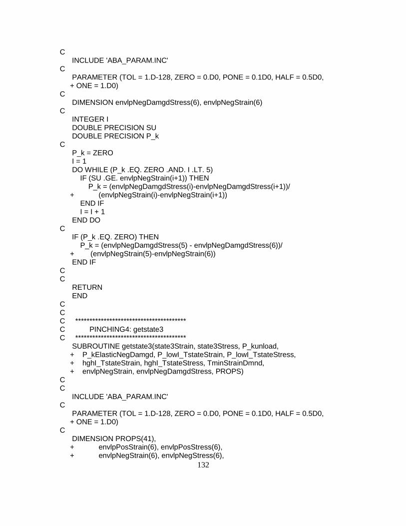
132
C INCLUDE 'ABA_PARAM.INC' C PARAMETER (TOL = 1.D-128, ZERO = 0.D0, PONE = 0.1D0, HALF = 0.5D0, + ONE = 1.D0) C DIMENSION envlpNegDamgdStress(6), envlpNegStrain(6) C INTEGER I DOUBLE PRECISION SU DOUBLE PRECISION P_k C P_k = ZERO I = 1 DO WHILE (P_k .EQ. ZERO .AND. I .LT. 5) IF (SU .GE. envlpNegStrain(i+1)) THEN P_k = (envlpNegDamgdStress(i)-envlpNegDamgdStress(i+1))/ + (envlpNegStrain(i)-envlpNegStrain(i+1)) END IF I = I + 1 END DO C IF (P_k .EQ. ZERO) THEN P_k = (envlpNegDamgdStress(5) - envlpNegDamgdStress(6))/ + (envlpNegStrain(5)-envlpNegStrain(6)) END IF C C RETURN END C C C *************************************** C PINCHING4: getstate3 C *************************************** SUBROUTINE getstate3(state3Strain, state3Stress, P_kunload, + P_kElasticNegDamgd, P_lowI_TstateStrain, P_lowI_TstateStress, + hghI_TstateStrain, hghI_TstateStress, TminStrainDmnd, + envlpNegStrain, envlpNegDamgdStress, PROPS) C C INCLUDE 'ABA_PARAM.INC' C PARAMETER (TOL = 1.D-128, ZERO = 0.D0, PONE = 0.1D0, HALF = 0.5D0, + ONE = 1.D0) C DIMENSION PROPS(41), + envlpPosStrain(6), envlpPosStress(6), + envlpNegStrain(6), envlpNegStress(6),
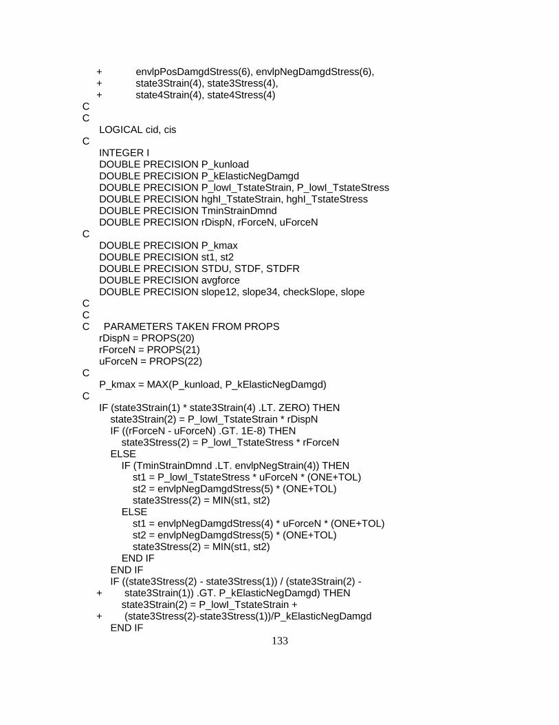
133
+ envlpPosDamgdStress(6), envlpNegDamgdStress(6), + state3Strain(4), state3Stress(4), + state4Strain(4), state4Stress(4) C C LOGICAL cid, cis C INTEGER I DOUBLE PRECISION P_kunload DOUBLE PRECISION P_kElasticNegDamgd DOUBLE PRECISION P_lowI_TstateStrain, P_lowI_TstateStress DOUBLE PRECISION hghI_TstateStrain, hghI_TstateStress DOUBLE PRECISION TminStrainDmnd DOUBLE PRECISION rDispN, rForceN, uForceN C DOUBLE PRECISION P_kmax DOUBLE PRECISION st1, st2 DOUBLE PRECISION STDU, STDF, STDFR DOUBLE PRECISION avgforce DOUBLE PRECISION slope12, slope34, checkSlope, slope C C C PARAMETERS TAKEN FROM PROPS rDispN = PROPS(20) rForceN = PROPS(21) uForceN = PROPS(22) C P_kmax = MAX(P_kunload, P_kElasticNegDamgd) C IF (state3Strain(1) * state3Strain(4) .LT. ZERO) THEN state3Strain(2) = P_lowI_TstateStrain * rDispN IF ((rForceN - uForceN) .GT. 1E-8) THEN state3Stress(2) = P_lowI_TstateStress * rForceN ELSE IF (TminStrainDmnd .LT. envlpNegStrain(4)) THEN st1 = P_lowI_TstateStress * uForceN * (ONE+TOL) st2 = envlpNegDamgdStress(5) * (ONE+TOL) state3Stress(2) = MIN(st1, st2) ELSE st1 = envlpNegDamgdStress(4) * uForceN * (ONE+TOL) st2 = envlpNegDamgdStress(5) * (ONE+TOL) state3Stress(2) = MIN(st1, st2) END IF END IF IF ((state3Stress(2) - state3Stress(1)) / (state3Strain(2) - + state3Strain(1)) .GT. P_kElasticNegDamgd) THEN state3Strain(2) = P_lowI_TstateStrain + + (state3Stress(2)-state3Stress(1))/P_kElasticNegDamgd END IF

134
IF (state3Strain(2) .GT. state3Strain(4)) THEN STDU = state3Strain(4) - state3Strain(1) STDF = state3Stress(4) - state3Stress(1) state3Strain(2) = state3Strain(1) + 0.33D0*STDU state3Strain(3) = state3Strain(1) + 0.67D0*STDU state3Stress(2) = state3Stress(1) + 0.33D0*STDF state3Stress(3) = state3Stress(1) + 0.67D0*STDF ELSE C PATH: IF (TminStrainDmnd .LT. envlpNegStrain(4)) THEN state3Stress(3) = uForceN * envlpNegDamgdStress(5) ELSE state3Stress(3) = uForceN * envlpNegDamgdStress(4) C PATH: END IF state3Strain(3) = hghI_TstateStrain - + (hghI_TstateStress-state3Stress(3))/P_kunload IF (state3Strain(3) .GT. state3Strain(4)) THEN STDU = state3Strain(4) - state3Strain(2) STDF = state3Stress(4) - state3Stress(2) state3Strain(3) = state3Strain(2) + HALF*STDU state3Stress(3) = state3Stress(2) + HALF*STDF ELSE IF ((state3Stress(3) - state3Stress(2))/ + (state3Strain(3) -state3Strain(2)) .GT. P_kmax) THEN C PATH: STDU = state3Strain(4) - state3Strain(1) STDF = state3Stress(4) - state3Stress(1) state3Strain(2) = state3Strain(1) + 0.33D0*STDU state3Strain(3) = state3Strain(1) + 0.67D0*STDU state3Stress(2) = state3Stress(1) + 0.33D0*STDF state3Stress(3) = state3Stress(1) + 0.67D0*STDF ELSE IF ((state3Strain(3) .LT. state3Strain(2)) .OR. + ((state3Stress(3)-state3Stress(2))/ + (state3Strain(3)-state3Strain(2)) .LT. 0)) THEN IF (state3Strain(3) .LT. ZERO) THEN STDU = state3Strain(4)-state3Strain(2) STDF = state3Stress(4)-state3Stress(2) state3Strain(3)=state3Strain(2)+HALF*STDU state3Stress(3)= state3Stress(2)+HALF*STDF ELSE IF (state3Strain(2) .GT. ZERO) THEN STDU = state3Strain(3)-state3Strain(1) STDF = state3Stress(3)-state3Stress(1) state3Strain(2)=state3Strain(1)+HALF*STDU state3Stress(2)=state3Stress(1)+HALF*STDF ELSE avgforce = HALF*(state3Stress(3) + + state3Stress(2)) STDFR = ZERO IF (avgforce .LT. ZERO) THEN

135
STDFR = -avgforce/100.0D0 ELSE STDFR = avgforce/100.0D0 END IF slope12 = (state3Stress(2) - + state3Stress(1))/(state3Strain(2) - state3Strain(1)) slope34 = (state3Stress(4) - + state3Stress(3))/(state3Strain(4) - state3Strain(3)) state3Stress(2) = avgforce - STDFR state3Stress(3) = avgforce + STDFR state3Strain(2) = state3Strain(1) + + (state3Stress(2) - state3Stress(1))/slope12 state3Strain(3) = state3Strain(4) - + (state3Stress(4) - state3Stress(3))/slope34 END IF END IF END IF ELSE STDU = state3Strain(4)-state3Strain(1) STDF = state3Stress(4)-state3Stress(1) state3Strain(2) = state3Strain(1) + 0.33D0*STDU; state3Strain(3) = state3Strain(1) + 0.67D0*STDU; state3Stress(2) = state3Stress(1) + 0.33D0*STDF; state3Stress(3) = state3Stress(1) + 0.67D0*STDF; END IF C checkSlope = state3Stress(1)/state3Strain(1) slope = ZERO C C FINAL CHECK I = 1 DO WHILE (I .LT. 4) STDU = state3Strain(i+1)-state3Strain(i) STDF = state3Stress(i+1)-state3Stress(i) IF (STDU .LT. ZERO .OR. STDF .LT. ZERO) THEN STDU = state3Strain(4)-state3Strain(1) STDF = state3Stress(4)-state3Stress(1) state3Strain(2) = state3Strain(1) + 0.33D0*STDU state3Strain(3) = state3Strain(1) + 0.67D0*STDU state3Stress(2) = state3Stress(1) + 0.33D0*STDF state3Stress(3) = state3Stress(1) + 0.67D0*STDF slope = STDF / STDU I = 4 END IF IF (slope .GT. 1.0D-8 .AND. slope .LT. checkSlope) THEN state3Strain(2) = ZERO; state3Stress(2) = ZERO; state3Strain(3) = state3Strain(4)*HALF state3Stress(3) = state3Stress(4)*HALF

136
END IF I = I + 1 END DO C C RETURN END C C C *************************************** C PINCHING4: getstate4 C *************************************** SUBROUTINE getstate4(state4Strain, state4Stress, P_kunload, + P_kElasticPosDamgd, P_lowI_TstateStrain,P_lowI_TstateStress, + hghI_TstateStrain, hghI_TstateStress, TmaxStrainDmnd, + envlpPosStrain, envlpPosDamgdStress, PROPS) C C INCLUDE 'ABA_PARAM.INC' C PARAMETER (TOL = 1.D-128, ZERO = 0.D0, PONE = 0.1D0, HALF = 0.5D0, + ONE = 1.D0) C DIMENSION PROPS(41), + envlpPosStrain(6), envlpPosStress(6), + envlpNegStrain(6), envlpNegStress(6), + envlpPosDamgdStress(6), envlpNegDamgdStress(6), + state4Strain(4), state4Stress(4) C C LOGICAL cid, cis C INTEGER I DOUBLE PRECISION P_kunload DOUBLE PRECISION P_kElasticPosDamgd DOUBLE PRECISION P_lowI_TstateStrain,P_lowI_TstateStress DOUBLE PRECISION hghI_TstateStrain, hghI_TstateStress DOUBLE PRECISION TmaxStrainDmnd DOUBLE PRECISION rDispP, rForceP, uForceP C DOUBLE PRECISION P_kmax DOUBLE PRECISION st1, st2 DOUBLE PRECISION STDU, STDF, STDFR DOUBLE PRECISION avgforce DOUBLE PRECISION slope12, slope34, checkSlope, slope C C C

137
C PARAMETERS TAKEN FROM PROPS rDispP = PROPS(17) rForceP = PROPS(18) uForceP = PROPS(19) C P_kmax = MAX(P_kunload, P_kElasticPosDamgd) C IF (state4Strain(1) * state4Strain(4) .LT. ZERO) THEN state4Strain(3) = hghI_TstateStrain * rDispP IF (uForceP .EQ. ZERO) THEN state4Stress(3) = hghI_TstateStress * rForceP ELSE IF (rForceP-uForceP .GT. 1.0D-8) THEN state4Stress(3) = hghI_TstateStress * rForceP ELSE IF (TmaxStrainDmnd .GT. envlpPosStrain(4)) THEN st1 = hghI_TstateStress * uForceP * (ONE+TOL) st2 = envlpNegDamgdStress(5) * (ONE+TOL) state4Stress(3) = MAX(st1, st2) ELSE st1 = envlpPosDamgdStress(4)*uForceP*(ONE+TOL) st2 = envlpPosDamgdStress(5)*(ONE+TOL) state4Stress(3) = MIN(st1, st2) END IF END IF IF ((state4Stress(4) - state4Stress(3)) / (state4Strain(4) - + state4Strain(3)) .GT. P_kElasticPosDamgd) THEN state4Strain(3) = hghI_TstateStrain - + (state4Stress(4)-state4Stress(3))/P_kElasticPosDamgd END IF IF (state4Strain(3) .LT. state4Strain(1)) THEN STDU = state4Strain(4) - state4Strain(1) STDF = state4Stress(4) - state4Stress(1) state4Strain(2) = state4Strain(1) + 0.33D0*STDU state4Strain(3) = state4Strain(1) + 0.67D0*STDU state4Stress(2) = state4Stress(1) + 0.33D0*STDF state4Stress(3) = state4Stress(1) + 0.67D0*STDF ELSE C PATH: IF (TmaxStrainDmnd .GT. envlpPosStrain(4)) THEN state4Stress(2) = uForceP * envlpPosDamgdStress(5) ELSE state4Stress(2) = uForceP * envlpPosDamgdStress(4) C PATH: END IF state4Strain(2) = P_lowI_TstateStrain + + (-P_lowI_TstateStress + state4Stress(2))/P_kunload IF (state4Strain(2) .LT. state4Strain(1)) THEN STDU = state4Strain(3) - state4Strain(1) STDF = state4Stress(3) - state4Stress(1)

138
state4Strain(2) = state4Strain(1) + HALF*STDU state4Stress(2) = state4Stress(1) + HALF*STDF ELSE IF ((state4Stress(3) - state4Stress(2))/ + (state4Strain(3) -state4Strain(2)) .GT. P_kmax) THEN C PATH: STDU = state4Strain(4) - state4Strain(1) STDF = state4Stress(4) - state4Stress(1) state4Strain(2) = state4Strain(1) + 0.33D0*STDU state4Strain(3) = state4Strain(1) + 0.67D0*STDU state4Stress(2) = state4Stress(1) + 0.33D0*STDF state4Stress(3) = state4Stress(1) + 0.67D0*STDF ELSE IF ((state4Strain(3) .LT. state4Strain(2)) .OR. + ((state4Stress(3)-state4Stress(2))/ + (state4Strain(3)-state4Strain(2)) .LT. ZERO)) THEN IF (state4Strain(2) .GT. ZERO) THEN STDU = state4Strain(3)-state4Strain(1) STDF = state4Stress(3)-state4Stress(1) state4Strain(2)=state4Strain(1)+HALF*STDU state4Stress(2)=state4Stress(1)+HALF*STDF ELSE IF (state4Strain(3) .LT. ZERO) THEN STDU = state4Strain(4)-state4Strain(2) STDF = state4Stress(4)-state4Stress(2) state4Strain(3)=state4Strain(2)+HALF*STDU state4Stress(3)=state4Stress(2)+HALF*STDF ELSE avgforce = HALF*(state4Stress(3) + + state4Stress(2)) STDFR = ZERO IF (avgforce .LT. ZERO) THEN STDFR = -avgforce/100.0D0 ELSE STDFR = avgforce/100.0D0 END IF slope12 = (state4Stress(2) - + state4Stress(1))/(state4Strain(2) - state4Strain(1)) slope34 = (state4Stress(4) - + state4Stress(3))/(state4Strain(4) - state4Strain(3)) state4Stress(2) = avgforce - STDFR state4Stress(3) = avgforce + STDFR state4Strain(2) = state4Strain(1) + + (state4Stress(2) - state4Stress(1))/slope12 state4Strain(3) = state4Strain(4) - + (state4Stress(4) - state4Stress(3))/slope34 END IF END IF END IF ELSE STDU = state4Strain(4)-state4Strain(1) STDF = state4Stress(4)-state4Stress(1)
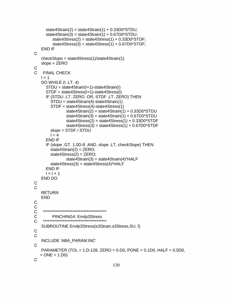
139
state4Strain(2) = state4Strain(1) + 0.33D0*STDU; state4Strain(3) = state4Strain(1) + 0.67D0*STDU; state4Stress(2) = state4Stress(1) + 0.33D0*STDF; state4Stress(3) = state4Stress(1) + 0.67D0*STDF; END IF C checkSlope = state4Stress(1)/state4Strain(1) slope = ZERO C C FINAL CHECK I = 1 DO WHILE (I .LT. 4) STDU = state4Strain(I+1)-state4Strain(I) STDF = state4Stress(I+1)-state4Stress(I) IF (STDU .LT. ZERO .OR. STDF .LT. ZERO) THEN STDU = state4Strain(4)-state4Strain(1) STDF = state4Stress(4)-state4Stress(1) state4Strain(2) = state4Strain(1) + 0.33D0*STDU state4Strain(3) = state4Strain(1) + 0.67D0*STDU state4Stress(2) = state4Stress(1) + 0.33D0*STDF state4Stress(3) = state4Stress(1) + 0.67D0*STDF slope = STDF / STDU I = 4 END IF IF (slope .GT. 1.0D-8 .AND. slope .LT. checkSlope) THEN state4Strain(2) = ZERO; state4Stress(2) = ZERO; state4Strain(3) = state4Strain(4)*HALF state4Stress(3) = state4Stress(4)*HALF END IF I = I + 1 END DO C C RETURN END C C C *************************************** C PINCHING4: Envlp3Stress C *************************************** SUBROUTINE Envlp3Stress(s3Strain,s3Stress,SU, f) C C INCLUDE 'ABA_PARAM.INC' C PARAMETER (TOL = 1.D-128, ZERO = 0.D0, PONE = 0.1D0, HALF = 0.5D0, + ONE = 1.D0) C

140
DIMENSION s3Strain(4), s3Stress(4) C INTEGER I DOUBLE PRECISION SU DOUBLE PRECISION P_k, f C P_k = ZERO I = 1 f = ZERO DO WHILE ((P_k .EQ. ZERO .OR. i .LE. 3) .AND. i .LE. 3) IF (SU .GE. s3Strain(i)) THEN P_k = (s3Stress(i+1)-s3Stress(i))/ + (s3Strain(i+1)-s3Strain(i)) f = s3Stress(i)+(SU-s3Strain(i))*P_k END IF I = I + 1 END DO IF (P_k .EQ. ZERO) THEN IF (SU .LT. s3Strain(1)) THEN I = 1 ELSE I = 3 END IF P_k = (s3Stress(i+1)-s3Stress(i))/(s3Strain(i+1)-s3Strain(i)) f = s3Stress(i)+(SU-s3Strain(i))*P_k END IF C C RETURN END C C C *************************************** C PINCHING4: Envlp3Tangent C *************************************** SUBROUTINE Envlp3Tangent(s3Strain,s3Stress,SU, P_k) C C INCLUDE 'ABA_PARAM.INC' C PARAMETER (TOL = 1.D-128, ZERO = 0.D0, PONE = 0.1D0, HALF = 0.5D0, + ONE = 1.D0) C DIMENSION s3Strain(4), s3Stress(4) C INTEGER I DOUBLE PRECISION SU DOUBLE PRECISION P_k C

141
P_k = ZERO I = 1 DO WHILE ((P_k .EQ. ZERO .OR. i .LE. 3) .AND. i .LE. 3) IF (SU .GE. s3Strain(i)) THEN P_k = (s3Stress(i+1)-s3Stress(i))/ + (s3Strain(i+1)-s3Strain(i)) END IF I = I + 1 END DO IF (P_k .EQ. ZERO) THEN IF (SU .LT. s3Strain(1)) THEN I = 1 ELSE I = 3 END IF P_k = (s3Stress(i+1)-s3Stress(i))/(s3Strain(i+1)-s3Strain(i)) END IF C C RETURN END C C C *************************************** C PINCHING4: Envlp4Stress C *************************************** SUBROUTINE Envlp4Stress(s4Strain,s4Stress,SU, f) C C INCLUDE 'ABA_PARAM.INC' C PARAMETER (TOL = 1.D-128, ZERO = 0.D0, PONE = 0.1D0, HALF = 0.5D0, + ONE = 1.D0) C DIMENSION s4Strain(4), s4Stress(4) C INTEGER I DOUBLE PRECISION SU DOUBLE PRECISION P_k, f C P_k = ZERO I = 1 f = ZERO DO WHILE ((P_k .EQ. ZERO .OR. i .LE. 3) .AND. i .LE. 3) IF (SU .GE. s4Strain(i)) THEN P_k = (s4Stress(i+1)-s4Stress(i))/ + (s4Strain(i+1)-s4Strain(i)) f = s4Stress(i)+(SU-s4Strain(i))*P_k END IF

142
I = I + 1 END DO IF (P_k .EQ. ZERO) THEN IF (SU .LT. s4Strain(1)) THEN I = 1 ELSE I = 3 END IF P_k = (s4Stress(i+1)-s4Stress(i))/(s4Strain(i+1)-s4Strain(i)) f = s4Stress(i)+(SU-s4Strain(i))*P_k END IF C C RETURN END C C C *************************************** C PINCHING4: Envlp4Tangent C *************************************** SUBROUTINE Envlp4Tangent(s4Strain,s4Stress, SU, P_k) C C INCLUDE 'ABA_PARAM.INC' C PARAMETER (TOL = 1.D-128, ZERO = 0.D0, PONE = 0.1D0, HALF = 0.5D0, + ONE = 1.D0) C DIMENSION s4Strain(4), s4Stress(4) C INTEGER I DOUBLE PRECISION SU DOUBLE PRECISION P_k C P_k = ZERO I = 1 DO WHILE ((P_k .EQ. ZERO .OR. i .LE. 3) .AND. (i .LE. 3)) IF (SU .GE. s4Strain(i)) THEN P_k = (s4Stress(i+1)-s4Stress(i))/ + (s4Strain(i+1)-s4Strain(i)) END IF I = I + 1 END DO IF (P_k .EQ. ZERO) THEN IF (SU .LT. s4Strain(1)) THEN I = 1 ELSE I = 3 END IF

143
P_k = (s4Stress(i+1)-s4Stress(i))/(s4Strain(i+1)-s4Strain(i)) END IF C C RETURN END C C C *************************************** C PINCHING4: updateDmg C *************************************** SUBROUTINE updateDmg(strain, dstrain, + TmaxStrainDmnd, TminStrainDmnd, + envlpPosStrain, envlpNegStrain, + envlpPosDamgdStress,envlpNegDamgdStress, + CnCycle,Tenergy,energyCapacity, + I_DmgCyc, elasticStrainEnergy, + P_kElasticPos,P_kElasticNeg, + TnCycle,TgammaK,TgammaD,TgammaF, + PROPS) C C INCLUDE 'ABA_PARAM.INC' C PARAMETER (TOL = 1.D-128, ZERO = 0.D0, PONE = 0.1D0, HALF = 0.5D0, + ONE = 1.D0) C DIMENSION PROPS(41), + envlpPosStrain(6), envlpPosStress(6), + envlpNegStrain(6), envlpNegStress(6), + envlpPosDamgdStress(6), envlpNegDamgdStress(6), + state3Strain(4), state3Stress(4), + state4Strain(4), state4Stress(4) C INTEGER I_DmgCyc DOUBLE PRECISION strain, dstrain DOUBLE PRECISION TmaxStrainDmnd, TminStrainDmnd DOUBLE PRECISION P_kElasticPos,P_kElasticNeg DOUBLE PRECISION CnCycle, TnCycle DOUBLE PRECISION Tenergy, energyCapacity, elasticStrainEnergy DOUBLE PRECISION TgammaK,TgammaD,TgammaF C DOUBLE PRECISION gammaK1, gammaK2, gammaK3, gammaK4, gammaKLimit DOUBLE PRECISION gammaD1, gammaD2, gammaD3, gammaD4, gammaDLimit DOUBLE PRECISION gammaF1, gammaF2, gammaF3, gammaF4, gammaFLimit C DOUBLE PRECISION tes DOUBLE PRECISION umaxAbs, uultAbs DOUBLE PRECISION gammaKLimEnv

144
C DOUBLE PRECISION EXTSTRESS DOUBLE PRECISION P_kminP, P_kminN, P_kmin DOUBLE PRECISION P_k1 C C UNZIP PARAMETERS FROM PROPS() gammaK1 = PROPS(23) gammaK2 = PROPS(24) gammaK3 = PROPS(25) gammaK4 = PROPS(26) gammaKLimit = PROPS(27) gammaD1 = PROPS(28) gammaD2 = PROPS(29) gammaD3 = PROPS(30) gammaD4 = PROPS(31) gammaDLimit = PROPS(32) gammaF1 = PROPS(33) gammaF2 = PROPS(34) gammaF3 = PROPS(35) gammaF4 = PROPS(36) gammaFLimit = PROPS(37) I_DmgCyc = INT(PROPS(39)) C tes = ZERO umaxAbs = MAX(TmaxStrainDmnd, -TminStrainDmnd) uultAbs = MAX(envlpPosStrain(5), -envlpNegStrain(5)) TnCycle = CnCycle + DABS(dstrain)/(4.0D0*umaxAbs) C IF ((strain .LT. uultAbs .AND. strain .GT. -uultAbs) .AND. + Tenergy .LT. energyCapacity) THEN TgammaK = gammaK1 * ((umaxAbs/uultAbs) ** gammaK3) TgammaD = gammaD1 * ((umaxAbs/uultAbs) ** gammaD3) TgammaF = gammaF1 * ((umaxAbs/uultAbs) ** gammaF3) C IF (Tenergy .GT. elasticStrainEnergy + .AND. I_DmgCyc .EQ. 0) THEN tes = (Tenergy-elasticStrainEnergy)/energyCapacity TgammaK = TgammaK + gammaK2 * (tes ** gammaK4) TgammaD = TgammaD + gammaD2 * (tes ** gammaD4) TgammaF = TgammaF + gammaF2 * (tes ** gammaF4) ELSE IF (I_DmgCyc .EQ. 1) THEN TgammaK = TgammaK + gammaK2 * (TnCycle ** gammaK4) TgammaD = TgammaD + gammaD2 * (TnCycle ** gammaD4) TgammaF = TgammaF + gammaF2 * (TnCycle ** gammaF4) END IF C CALL posEnvlpStress(TmaxStrainDmnd, envlpPosDamgdStress, + envlpPosStrain, EXTSTRESS)

145
P_kminP = EXTSTRESS/TmaxStrainDmnd CALL negEnvlpStress(TminStrainDmnd, envlpNegDamgdStress, + envlpNegStrain, EXTSTRESS) P_kminN = EXTSTRESS/TminStrainDmnd P_kmin = MAX(P_kminP/P_kElasticPos, P_kminN/P_kElasticNeg) gammaKLimEnv = MAX(ZERO, (ONE-P_kmin)) C P_k1 = MIN(TgammaK, gammaKLimit) TgammaK = MIN(P_k1, gammaKLimEnv) TgammaD = MIN(TgammaD, gammaDLimit) TgammaF = MIN(TgammaF, gammaFLimit) ELSE IF (strain .LT. uultAbs .AND. strain .GT.-uultAbs) THEN CALL posEnvlpStress(TmaxStrainDmnd, envlpPosDamgdStress, + envlpPosStrain, EXTSTRESS) P_kminP = EXTSTRESS/TmaxStrainDmnd CALL negEnvlpStress(TminStrainDmnd, envlpNegDamgdStress, + envlpNegStrain, EXTSTRESS) P_kminN = EXTSTRESS/TminStrainDmnd P_kmin = MAX(P_kminP/P_kElasticPos, P_kminN/P_kElasticNeg) gammaKLimEnv = MAX(ZERO, (ONE-P_kmin)) C TgammaK = MIN(gammaKLimit, gammaKLimEnv) TgammaD = MIN(TgammaD, gammaDLimit) TgammaF = MIN(TgammaF, gammaFLimit) C END IF C C RETURN END C C C *************************************** C PINCHING4: commitState C *************************************** SUBROUTINE commitState(I_Tstate,dstrain,TstrainRate, + P_lowI_TstateStrain,P_lowI_TstateStress, + hghI_TstateStrain,hghI_TstateStress, + TminStrainDmnd,TmaxStrainDmnd, + Tenergy,Tstress,Tstrain, + TgammaK,TgammaD,TgammaF, + P_kElasticPos,P_kElasticNeg, + gammaKUsed,gammaFUsed, + envlpPosStress,envlpNegStress,TnCycle, + I_Cstate,CstrainRate, + P_lowI_CstateStrain,P_lowI_CstateStress, + hghI_CstateStrain,hghI_CstateStress, + CminStrainDmnd,CmaxStrainDmnd, + Cenergy,Cstress,Cstrain,

146
+ CgammaK,CgammaD,CgammaF, + P_kElasticPosDamgd,P_kElasticNegDamgd, + uMaxDamgd,uMinDamgd, + envlpPosDamgdStress,envlpNegDamgdStress,CnCycle) C C INCLUDE 'ABA_PARAM.INC' C PARAMETER (TOL = 1.D-128, ZERO = 0.D0, PONE = 0.1D0, HALF = 0.5D0, + ONE = 1.D0) C DIMENSION PROPS(41), + envlpPosStrain(6), envlpPosStress(6), + envlpNegStrain(6), envlpNegStress(6), + envlpPosDamgdStress(6), envlpNegDamgdStress(6), + state3Strain(4), state3Stress(4), + state4Strain(4), state4Stress(4) C C INTEGER I_Cstate, I_Tstate DOUBLE PRECISION dstrain DOUBLE PRECISION Cstrain, Cstress, CstrainRate DOUBLE PRECISION Tstrain, Tstress, TstrainRate DOUBLE PRECISION P_lowI_TstateStrain, P_lowI_TstateStress DOUBLE PRECISION hghI_TstateStrain, hghI_TstateStress DOUBLE PRECISION P_lowI_CstateStrain,P_lowI_CstateStress DOUBLE PRECISION hghI_CstateStrain,hghI_CstateStress DOUBLE PRECISION TminStrainDmnd,TmaxStrainDmnd DOUBLE PRECISION CminStrainDmnd,CmaxStrainDmnd DOUBLE PRECISION Cenergy, Tenergy DOUBLE PRECISION CnCycle, TnCycle DOUBLE PRECISION TgammaK,TgammaD,TgammaF DOUBLE PRECISION CgammaK,CgammaD,CgammaF DOUBLE PRECISION gammaKUsed,gammaFUsed DOUBLE PRECISION P_kElasticPos,P_kElasticNeg DOUBLE PRECISION P_kElasticPosDamgd,P_kElasticNegDamgd DOUBLE PRECISION uMaxDamgd,uMinDamgd C I_Cstate = I_Tstate C IF (dstrain .GT. 1.0D-12 .OR. dstrain<-(1.0D-12)) THEN CstrainRate = dstrain ELSE CstrainRate = TstrainRate END IF C P_lowI_CstateStrain = P_lowI_TstateStrain P_lowI_CstateStress = P_lowI_TstateStress hghI_CstateStrain = hghI_TstateStrain

147
hghI_CstateStress = hghI_TstateStress CminStrainDmnd = TminStrainDmnd CmaxStrainDmnd = TmaxStrainDmnd Cenergy = Tenergy C Cstress = Tstress Cstrain = Tstrain C CgammaK = TgammaK CgammaD = TgammaD CgammaF = TgammaF C P_kElasticPosDamgd = P_kElasticPos*(1 - gammaKUsed) P_kElasticNegDamgd = P_kElasticNeg*(1 - gammaKUsed) C uMaxDamgd = TmaxStrainDmnd*(1 + CgammaD) uMinDamgd = TminStrainDmnd*(1 + CgammaD) C envlpPosDamgdStress = envlpPosStress*(1-gammaFUsed) envlpNegDamgdStress = envlpNegStress*(1-gammaFUsed) C CnCycle = TnCycle C C RETURN END C C C C C *************************************** C PINCHING4 INTERFACE:SPIN2UEL C *************************************** SUBROUTINE SPIN2UEL(envlpPosDamgdStress, envlpNegDamgdStress, +state3Strain, state3Stress, state4Strain, state4Stress, +I_Cstate, Cstrain, Cstress, CstrainRate, P_lowI_CstateStrain, +P_lowI_CstateStress, hghI_CstateStrain, hghI_CstateStress, +CminStrainDmnd, CmaxStrainDmnd, Cenergy, CgammaK, +CgammaD, CgammaF, Ttangent, gammaKUsed, gammaFUsed, +P_kElasticPosDamgd, P_kElasticNegDamgd, uMaxDamgd,uMinDamgd, +P_kunload, CnCycle, elasticStrainEnergy, strain, dstrain, +SPR_DISP, SPR_F, SPR_K, SVARS, I_SPR_NUM) C C INCLUDE 'ABA_PARAM.INC' C PARAMETER (TOL = 1.D-128, ZERO = 0.D0, PONE = 0.1D0, HALF = 0.5D0, + ONE = 1.D0) C

148
DIMENSION envlpPosDamgdStress(6), envlpNegDamgdStress(6), + state3Strain(4), state3Stress(4), + state4Strain(4), state4Stress(4), + SVARS(200) C DOUBLE PRECISION strain, dstrain DOUBLE PRECISION Cstrain, Cstress, CstrainRate DOUBLE PRECISION P_lowI_CstateStrain, P_lowI_CstateStress DOUBLE PRECISION hghI_CstateStrain, hghI_CstateStress DOUBLE PRECISION CminStrainDmnd, CmaxStrainDmnd DOUBLE PRECISION Cenergy DOUBLE PRECISION CgammaK, CgammaD, CgammaF DOUBLE PRECISION Ttangent DOUBLE PRECISION gammaKUsed, gammaFUsed DOUBLE PRECISION P_kElasticPosDamgd, P_kElasticNegDamgd DOUBLE PRECISION uMaxDamgd,uMinDamgd DOUBLE PRECISION P_kunload DOUBLE PRECISION CnCycle DOUBLE PRECISION elasticStrainEnergy DOUBLE PRECISION SPR_DISP, SPR_K, SPR_F C INTEGER I_Cstate C INTEGER I_SPR_NUM C C IF (I_SPR_NUM .EQ. 1) THEN SVARS(1) = envlpPosDamgdStress(1) SVARS(2) = envlpPosDamgdStress(2) SVARS(3) = envlpPosDamgdStress(3) SVARS(4) = envlpPosDamgdStress(4) SVARS(5) = envlpPosDamgdStress(5) SVARS(6) = envlpPosDamgdStress(6) SVARS(7) = envlpNegDamgdStress(1) SVARS(8) = envlpNegDamgdStress(2) SVARS(9) = envlpNegDamgdStress(3) SVARS(10) = envlpNegDamgdStress(4) SVARS(11) = envlpNegDamgdStress(5) SVARS(12) = envlpNegDamgdStress(6) SVARS(13) = state3Strain(1) SVARS(14) = state3Strain(2) SVARS(15) = state3Strain(3) SVARS(16) = state3Strain(4) SVARS(17) = state3Stress(1) SVARS(18) = state3Stress(2) SVARS(19) = state3Stress(3) SVARS(20) = state3Stress(4) SVARS(21) = state4Strain(1) SVARS(22) = state4Strain(2)

149
SVARS(23) = state4Strain(3) SVARS(24) = state4Strain(4) SVARS(25) = state4Stress(1) SVARS(26) = state4Stress(2) SVARS(27) = state4Stress(3) SVARS(28) = state4Stress(4) SVARS(29) = DBLE(I_Cstate) SVARS(30) = Cstrain SVARS(31) = Cstress SVARS(32) = CstrainRate SVARS(33) = P_lowI_CstateStrain SVARS(34) = P_lowI_CstateStress SVARS(35) = hghI_CstateStrain SVARS(36) = hghI_CstateStress SVARS(37) = CminStrainDmnd SVARS(38) = CmaxStrainDmnd SVARS(39) = Cenergy SVARS(40) = CgammaK SVARS(41) = CgammaD SVARS(42) = CgammaF SVARS(43) = gammaKUsed SVARS(44) = gammaFUsed SVARS(45) = Ttangent SVARS(46) = P_kElasticPosDamgd SVARS(47) = P_kElasticNegDamgd SVARS(48) = uMaxDamgd SVARS(49) = uMinDamgd SVARS(50) = P_kunload SVARS(51) = CnCycle SVARS(52) = elasticStrainEnergy SVARS(53) = strain SVARS(54) = dstrain SVARS(55) = SPR_DISP SVARS(56) = SPR_F SVARS(57) = SPR_K ELSE IF (I_SPR_NUM .EQ. 2) THEN SVARS(58) = envlpPosDamgdStress(1) SVARS(59) = envlpPosDamgdStress(2) SVARS(60) = envlpPosDamgdStress(3) SVARS(61) = envlpPosDamgdStress(4) SVARS(62) = envlpPosDamgdStress(5) SVARS(63) = envlpPosDamgdStress(6) SVARS(64) = envlpNegDamgdStress(1) SVARS(65) = envlpNegDamgdStress(2) SVARS(66) = envlpNegDamgdStress(3) SVARS(67) = envlpNegDamgdStress(4) SVARS(68) = envlpNegDamgdStress(5) SVARS(69) = envlpNegDamgdStress(6) SVARS(70) = state3Strain(1)

150
SVARS(71) = state3Strain(2) SVARS(72) = state3Strain(3) SVARS(73) = state3Strain(4) SVARS(74) = state3Stress(1) SVARS(75) = state3Stress(2) SVARS(76) = state3Stress(3) SVARS(77) = state3Stress(4) SVARS(78) = state4Strain(1) SVARS(79) = state4Strain(2) SVARS(80) = state4Strain(3) SVARS(81) = state4Strain(4) SVARS(82) = state4Stress(1) SVARS(83) = state4Stress(2) SVARS(84) = state4Stress(3) SVARS(85) = state4Stress(4) SVARS(86) = DBLE(I_Cstate) SVARS(87) = Cstrain SVARS(88) = Cstress SVARS(89) = CstrainRate SVARS(90) = P_lowI_CstateStrain SVARS(91) = P_lowI_CstateStress SVARS(92) = hghI_CstateStrain SVARS(93) = hghI_CstateStress SVARS(94) = CminStrainDmnd SVARS(95) = CmaxStrainDmnd SVARS(96) = Cenergy SVARS(97) = CgammaK SVARS(98) = CgammaD SVARS(99) = CgammaF SVARS(100) = gammaKUsed SVARS(101) = gammaFUsed SVARS(102) = Ttangent SVARS(103) = P_kElasticPosDamgd SVARS(104) = P_kElasticNegDamgd SVARS(105) = uMaxDamgd SVARS(106) = uMinDamgd SVARS(107) = P_kunload SVARS(108) = CnCycle SVARS(109) = elasticStrainEnergy SVARS(110) = strain SVARS(111) = dstrain SVARS(112) = SPR_DISP SVARS(113) = SPR_F SVARS(114) = SPR_K END IF C C RETURN END

151
C C C *************************************** C PINCHING4 INTERFACE:SUEL2PIN C *************************************** SUBROUTINE SUEL2PIN(envlpPosDamgdStress, envlpNegDamgdStress, +state3Strain, state3Stress, state4Strain, state4Stress, +I_Cstate, Cstrain, Cstress, CstrainRate, P_lowI_CstateStrain, +P_lowI_CstateStress, hghI_CstateStrain, hghI_CstateStress, +CminStrainDmnd, CmaxStrainDmnd, Cenergy, CgammaK, +CgammaD, CgammaF, Ttangent, gammaKUsed, gammaFUsed, +P_kElasticPosDamgd, P_kElasticNegDamgd, uMaxDamgd,uMinDamgd, +P_kunload, CnCycle, elasticStrainEnergy, +SPR_F, SPR_K, SVARS, I_SPR_NUM) C C INCLUDE 'ABA_PARAM.INC' C PARAMETER (TOL = 1.D-128, ZERO = 0.D0, PONE = 0.1D0, HALF = 0.5D0, + ONE = 1.D0) C DIMENSION envlpPosDamgdStress(6), envlpNegDamgdStress(6), + state3Strain(4), state3Stress(4), + state4Strain(4), state4Stress(4), SVARS(200) C DOUBLE PRECISION strain, dstrain DOUBLE PRECISION Cstrain, Cstress, CstrainRate DOUBLE PRECISION P_lowI_CstateStrain, P_lowI_CstateStress DOUBLE PRECISION hghI_CstateStrain, hghI_CstateStress DOUBLE PRECISION CminStrainDmnd, CmaxStrainDmnd DOUBLE PRECISION Cenergy DOUBLE PRECISION CgammaK, CgammaD, CgammaF DOUBLE PRECISION Ttangent DOUBLE PRECISION gammaKUsed, gammaFUsed DOUBLE PRECISION P_kElasticPosDamgd, P_kElasticNegDamgd DOUBLE PRECISION uMaxDamgd,uMinDamgd DOUBLE PRECISION P_kunload DOUBLE PRECISION CnCycle DOUBLE PRECISION elasticStrainEnergy DOUBLE PRECISION SPR_DISP, SPR_K, SPR_F C INTEGER I_Cstate C INTEGER I_SPR_NUM C IF (I_SPR_NUM .EQ. 1) THEN envlpPosDamgdStress(1) = SVARS(1) envlpPosDamgdStress(2) = SVARS(2) envlpPosDamgdStress(3) = SVARS(3)

152
envlpPosDamgdStress(4) = SVARS(4) envlpPosDamgdStress(5) = SVARS(5) envlpPosDamgdStress(6) = SVARS(6) envlpNegDamgdStress(1) = SVARS(7) envlpNegDamgdStress(2) = SVARS(8) envlpNegDamgdStress(3) = SVARS(9) envlpNegDamgdStress(4) = SVARS(10) envlpNegDamgdStress(5) = SVARS(11) envlpNegDamgdStress(6) = SVARS(12) state3Strain(1) = SVARS(13) state3Strain(2) = SVARS(14) state3Strain(3) = SVARS(15) state3Strain(4) = SVARS(16) state3Stress(1) = SVARS(17) state3Stress(2) = SVARS(18) state3Stress(3) = SVARS(19) state3Stress(4) = SVARS(20) state4Strain(1) = SVARS(21) state4Strain(2) = SVARS(22) state4Strain(3) = SVARS(23) state4Strain(4) = SVARS(24) state4Stress(1) = SVARS(25) state4Stress(2) = SVARS(26) state4Stress(3) = SVARS(27) state4Stress(4) = SVARS(28) I_Cstate = INT(SVARS(29)) Cstrain = SVARS(30) Cstress = SVARS(31) CstrainRate = SVARS(32) P_lowI_CstateStrain = SVARS(33) P_lowI_CstateStress = SVARS(34) hghI_CstateStrain = SVARS(35) hghI_CstateStress = SVARS(36) CminStrainDmnd = SVARS(37) CmaxStrainDmnd = SVARS(38) Cenergy = SVARS(39) CgammaK = SVARS(40) CgammaD = SVARS(41) CgammaF = SVARS(42) gammaKUsed = SVARS(43) gammaFUsed = SVARS(44) Ttangent = SVARS(45) P_kElasticPosDamgd = SVARS(46) P_kElasticNegDamgd = SVARS(47) uMaxDamgd = SVARS(48) uMinDamgd = SVARS(49) P_kunload = SVARS(50) CnCycle = SVARS(51) elasticStrainEnergy = SVARS(52)

153
SPR_F = SVARS(56) SPR_K = SVARS(57) ELSE IF (I_SPR_NUM .EQ. 2) THEN envlpPosDamgdStress(1) = SVARS(58) envlpPosDamgdStress(2) = SVARS(59) envlpPosDamgdStress(3) = SVARS(60) envlpPosDamgdStress(4) = SVARS(61) envlpPosDamgdStress(5) = SVARS(62) envlpPosDamgdStress(6) = SVARS(63) envlpNegDamgdStress(1) = SVARS(64) envlpNegDamgdStress(2) = SVARS(65) envlpNegDamgdStress(3) = SVARS(66) envlpNegDamgdStress(4) = SVARS(67) envlpNegDamgdStress(5) = SVARS(68) envlpNegDamgdStress(6) = SVARS(69) state3Strain(1) = SVARS(70) state3Strain(2) = SVARS(71) state3Strain(3) = SVARS(72) state3Strain(4) = SVARS(73) state3Stress(1) = SVARS(74) state3Stress(2) = SVARS(75) state3Stress(3) = SVARS(76) state3Stress(4) = SVARS(77) state4Strain(1) = SVARS(78) state4Strain(2) = SVARS(79) state4Strain(3) = SVARS(80) state4Strain(4) = SVARS(81) state4Stress(1) = SVARS(82) state4Stress(2) = SVARS(83) state4Stress(3) = SVARS(84) state4Stress(4) = SVARS(85) I_Cstate = INT(SVARS(86)) Cstrain = SVARS(87) Cstress = SVARS(88) CstrainRate = SVARS(89) P_lowI_CstateStrain = SVARS(90) P_lowI_CstateStress = SVARS(91) hghI_CstateStrain = SVARS(92) hghI_CstateStress = SVARS(93) CminStrainDmnd = SVARS(94) CmaxStrainDmnd = SVARS(95) Cenergy = SVARS(96) CgammaK = SVARS(97) CgammaD = SVARS(98) CgammaF = SVARS(99) gammaKUsed = SVARS(100) gammaFUsed = SVARS(101) Ttangent = SVARS(102) P_kElasticPosDamgd = SVARS(103)

154
P_kElasticNegDamgd = SVARS(104) uMaxDamgd = SVARS(105) uMinDamgd = SVARS(106) P_kunload = SVARS(107) CnCycle = SVARS(108) elasticStrainEnergy = SVARS(109) SPR_F = SVARS(113) SPR_K = SVARS(114) END IF C C RETURN END C C C ***********************************************************************************************************

155
APPENDIX D USER ELEMENT SUBROUTINE EXPLICIT CODE
(VUEL)
C *********************************************************************************************************** C ABAQUS/Explicit User Element Subroutine (VUEL) C --- for Fasterner-Based Shear Wall/Diaphragm Analysis --- C ----------------------------------------------------------------------- C author: Chu Ding ([email protected]) C advior: Dr. Cristopher D. Moen ([email protected]) C website: http://www.moen.cee.vt.edu/ C ***********************************************************************************************************subroutine vuel( * nblock, c to be defined * rhs,amass,dtimeStable, * svars,nsvars, * energy, c * nnode,ndofel, * props,nprops, * jprops,njprops, * coords,ncrd, * u,du,v,a, * jtype,jelem, * time,period,dtimeCur,dtimePrev,kstep,kinc,lflags, * dMassScaleFactor, * predef,npredef, * jdltyp,adlmag) include 'vaba_param.inc' parameter ( zero = 0.d0, half = 0.5d0, one = 1.d0, two=2.d0 ) c operation code parameter ( jMassCalc = 1, * jIntForceAndDtStable = 2, * jExternForce = 3) c c flags parameter (iProcedure = 1, * iNlgeom = 2,

156
* iOpCode = 3, * nFlags = 3) c time parameter (iStepTime = 1, * iTotalTime = 2, * nTime = 2) c procedure flags parameter ( jDynExplicit = 17 ) c energies parameter ( iElPd = 1, * iElCd = 2, * iElIe = 3, * iElTs = 4, * iElDd = 5, * iElBv = 6, * iElDe = 7, * iElHe = 8, * iElKe = 9, * iElTh = 10, * iElDmd = 11, * iElDc = 12, * nElEnergy = 12) c predefined variables parameter ( iPredValueNew = 1, * iPredValueOld = 2, * nPred = 2) c indexing in a 3-long vector parameter (factorStable = 0.99d0) **------------------------------------ C dimension rhs(nblock,ndofel), amass(nblock,ndofel,ndofel), * dtimeStable(nblock), * svars(nblock,nsvars), energy(nblock,nElEnergy), * props(nprops), jprops(njprops), * jelem(nblock), time(nTime), lflags(nFlags), * coords(nblock,nnode,ncrd), u(nblock,ndofel), * du(nblock,ndofel), v(nblock,ndofel), a(nblock, ndofel), * dMassScaleFactor(nblock), * predef(nblock, nnode, npredef, nPred), adlmag(nblock) DIMENSION SRESID(6) REAL SPR_DISP, SPR_F, SPR_K

157
REAL SPR_LEN, SPR_COS_X, SPR_COS_Y, SPR_SGN REAL SPR_DISP_X, SPR_DISP_Y REAL SPR_F_WD, SPR_K_WD REAL SPR_ORIENT_1, SPR_ORIENT_2 INTEGER KORIENT CHARACTER FILENAME*200 CHARACTER*(*) FILEPATH C -------------- Choose spring data output path -------------- C ********************************************************************************************** PARAMETER (FILEPATH = 'E:\Onedrive\VT_RESEARCH\UEL work\vuel construction\test elem formu\test_energy\vuel_method\') C ********************************************************************************************** C -------------- Select your spring type -------------- C ********************************************************************************************** c * 0: Default deformation quadrants, 1: Displacement-based deformation quadrants KORIENT = 1 C ********************************************************************************************** c c if (jtype .eq. 2 .and. * lflags(iProcedure).eq.jDynExplicit) then c initialize default dynamics parameters eDampTra = zero am0 = 4.5D-5 c use original distance to compute mass if ( lflags(iOpCode).eq.jMassCalc ) then ! loop over every user element do kblock = 1, nblock amass(kblock,1,1) = am0 amass(kblock,2,2) = am0 amass(kblock,3,3) = am0 amass(kblock,4,4) = am0 amass(kblock,5,5) = am0 amass(kblock,6,6) = am0 end do c update right-hand side vetor and stable time increment else if ( lflags(iOpCode) .eq. * jIntForceAndDtStable) then ! loop over every user element do kblock = 1, nblock amElem0 = two * am0 area = vol0/alen **------------------------------------ c * -------- update spring geometry -------- *

158
call SGEOM(U,COORDS,SPR_LEN,SPR_DISP,SPR_DISP_WD, +SPR_COS_X,SPR_COS_Y, SPR_DISP_X,SPR_DISP_Y,PROPS,SVARS,kblock) alen = SPR_DISP **------------------------------------ * * -------- generate deformation quadrant -------- * IF (KORIENT .EQ. 1) THEN IF (SVARS(kblock,128) .EQ. 0.0) THEN C * Use default deformation quadrant when deformation is "zero" IF (ABS(SPR_DISP) .LE. 2.0 * TOL) THEN SVARS(kblock,129) = 1.D0/SQRT(2.0) SVARS(kblock,130) = 1.D0/SQRT(2.0) ELSE C * Now use displacement-based quadrant C * Save spring orientation SVARS(kblock,129) = SPR_COS_X SVARS(kblock,130) = SPR_COS_Y SVARS(kblock,128) = SVARS(kblock,128)+1.0 END IF END IF C * Retrieve spring orientation SPR_ORIENT_1 = SVARS(kblock,129) SPR_ORIENT_2 = SVARS(kblock,130) C * Default deformation quadrant ELSE SPR_ORIENT_1 = 1.D0/SQRT(2.0) SPR_ORIENT_2 = 1.D0/SQRT(2.0) END IF **------------------------------------ C * -------- adjust spring deformation sign -------- * SPR_SGN = 1.0 C * For the case of "real compression" IF (SPR_DISP .LT. 0.0) THEN SPR_SGN = 1.0 C * For the case of "fake compression" determined by deformation quadrants ELSE IF (SPR_DISP_X .NE. 0. .AND. SPR_DISP_Y .NE. 0.) THEN IF (SPR_ORIENT_1 * SPR_DISP_X + SPR_ORIENT_2 * +SPR_DISP_Y .LT. 0.) THEN SPR_SGN = -1.0 END IF END IF C * Spring deformation is assinged with positive or negative sign SPR_DISP = SPR_SGN * SPR_DISP **------------------------------------ c * -------- update radial spring force and stifness -------- * I_SPR_NUM = 1 call PINCHING4(PROPS,SVARS,SPR_DISP,SPR_K,SPR_F,KINC, +I_SPR_NUM,kblock) ak = SPR_K fElasTra = SPR_F

159
forceTra = fElasTra **------------------------------------ c * -------- update withdrawl spring force -------- * SPR_K_WD = 1.E8 SPR_F_WD = SPR_DISP_WD * SPR_K_WD **------------------------------------ c * -------- update spring nodal force vector -------- * DO K1 = 1, 6 SRESID(K1) = ZERO END DO call SNFORCE(PROPS, SPR_F, SPR_COS_X, SPR_COS_Y, SRESID, +SPR_SGN, SPR_F_WD) RHS(kblock,1) = SRESID(1) RHS(kblock,2) = SRESID(2) RHS(kblock,3) = SRESID(3) RHS(kblock,4) = SRESID(4) RHS(kblock,5) = SRESID(5) RHS(kblock,6) = SRESID(6) **------------------------------------ c * -------- undamped stable time increment for translations -------- * dtTrialTransl = sqrt(amElem0/ak) c damped stable time increment; since eDampTra=0, the c stable time increment does not change because of damping critDampTransl = two*sqrt(amElem0*ak) csiTra = eDampTra/critDampTransl factDamp = sqrt(one+csiTra*csiTra) - csiTra dtTrialTransl = dtTrialTransl*factDamp*factorStable dtimeStable(kblock) = dtTrialTransl **------------------------------------ c * -------- update internal energy -------- * SVARS(kblock,141) = SVARS(kblock,142) SVARS(kblock,142) = SPR_DISP SVARS(kblock,143) = SVARS(kblock,144) SVARS(kblock,144) = SPR_F SPR_DISP1 = SVARS(kblock,141) SPR_DISP2 = SVARS(kblock,142) SPR_F1 = SVARS(kblock,143) SPR_F2 = SVARS(kblock,144) SPR_ENERGY = half*(SPR_F2+SPR_F1)*(SPR_DISP2-SPR_DISP1) SVARS(kblock,145) = SVARS(kblock,145) + SPR_ENERGY energy(kblock, iElIe) = SVARS(kblock,145) **------------------------------------ c * -------- output spring load history -------- * 900 FORMAT(I10, F20.8, F20.8, F20.8, F20.8) c WRITE(FILENAME, fmt='(a, I0, a)') FILEPATH, jelem(nblock), ".txt" OPEN(300, FILE=FILENAME, STATUS='UNKNOWN', POSITION='APPEND') WRITE(300, 900) KINC, SPR_DISP, SPR_F, SPR_K, energy(kblock, iElIe) CLOSE(300)

160
**------------------------------------ end do else if ( lflags(iOpCode) .eq. * jExternForce) then if (jdltyp.eq.123) then do kblock = 1, nblock rhs(kblock,4) = adlmag(kblock) end do end if end if end if c return end c c C ***************************************************************** C PINCHING4 ROUTINE C ***************************************************************** SUBROUTINE PINCHING4(PROPS,SVARS,SPR_DISP,SPR_K,SPR_F,KINC, +I_SPR_NUM,kblock) C C C include 'vaba_param.inc' C PARAMETER (TOL = 1.E-32) C DIMENSION PROPS(41), SVARS(kblock,200), + envlpPosStrain(6), envlpPosStress(6), + envlpNegStrain(6), envlpNegStress(6), + envlpPosDamgdStress(6), envlpNegDamgdStress(6), + state3Strain(4), state3Stress(4), + state4Strain(4), state4Stress(4) C INTEGER I_Cstate, I_Tstate INTEGER I_DmgCyc REAL strain, dstrain REAL Cstrain, Cstress, CstrainRate REAL Tstrain, Tstress, TstrainRate REAL P_lowI_CstateStrain, P_lowI_CstateStress REAL hghI_CstateStrain, hghI_CstateStress REAL CminStrainDmnd, CmaxStrainDmnd REAL TminStrainDmnd,TmaxStrainDmnd REAL elasticStrainEnergy, energyCapacity REAL Cenergy, CnCycle REAL Tenergy, TnCycle REAL CgammaK, CgammaD, CgammaF REAL TgammaD, TgammaK, TgammaF

161
REAL gammaKUsed, gammaFUsed REAL Ttangent, P_kunload REAL P_kElasticPosDamgd, P_kElasticNegDamgd REAL P_kElasticPos,P_kElasticNeg REAL uMaxDamgd, uMinDamgd C REAL SPR_K, SPR_F, SPR_DISP C INTEGER I_SPR_NUM C C C ASSIGN SVARS VALUES TO PINCHING4 LOCAL VARIABLES CALL SUEL2PIN(envlpPosDamgdStress, envlpNegDamgdStress, +state3Strain, state3Stress, state4Strain, state4Stress, +I_Cstate, Cstrain, Cstress, CstrainRate, P_lowI_CstateStrain, +P_lowI_CstateStress, hghI_CstateStrain, hghI_CstateStress, +CminStrainDmnd, CmaxStrainDmnd, Cenergy, CgammaK, +CgammaD, CgammaF, Ttangent, gammaKUsed, gammaFUsed, +P_kElasticPosDamgd, P_kElasticNegDamgd, uMaxDamgd,uMinDamgd, +P_kunload, CnCycle, elasticStrainEnergy, +SPR_F, SPR_K, SVARS, I_SPR_NUM, kblock) C C CONVERT UEL VARIABLES TO PINCHING4 LOCAL VARIABLES strain = SPR_DISP C C ***************************************************************** CALL SetEnvelop(PROPS, SVARS, envlpPosStrain, + envlpPosStress, envlpNegStrain, envlpNegStress, + P_kElasticPos,P_kElasticNeg, energyCapacity,kblock) C C IF (KINC .EQ. 1 .OR. KINC .EQ. 0) THEN CALL revertToStart(envlpPosStrain, envlpPosStress, + envlpNegStrain, envlpNegStress, + P_kElasticPos,P_kElasticNeg, + I_Cstate,Cstrain,Cstress,CstrainRate, + P_lowI_CstateStrain,P_lowI_CstateStress, + hghI_CstateStrain,hghI_CstateStress, + CminStrainDmnd,CmaxStrainDmnd, + Cenergy,CgammaK,CgammaD,CgammaF,CnCycle, + Ttangent,dstrain,gammaKUsed,gammaFUsed, + P_kElasticPosDamgd,P_kElasticNegDamgd, + uMaxDamgd,uMinDamgd, + envlpPosDamgdStress, envlpNegDamgdStress) C C ELSE CALL revertToLastCommit(I_Cstate,CstrainRate, + P_lowI_CstateStrain,P_lowI_CstateStress,

162
+ hghI_CstateStrain,hghI_CstateStress, + CminStrainDmnd,CmaxStrainDmnd, + Cenergy,Cstrain,Cstress, + CgammaD,CgammaK,CgammaF,CnCycle, + I_Tstate,TstrainRate, + P_lowI_TstateStrain,P_lowI_TstateStress, + hghI_TstateStrain,hghI_TstateStress, + TminStrainDmnd,TmaxStrainDmnd, + Tenergy,Tstrain,Tstress, + TgammaD,TgammaK,TgammaF,TnCycle) END IF C C CALL setTrialStrain(strain,CstrainRate,I_Cstate,Cenergy, + P_lowI_CstateStrain,hghI_CstateStrain, + P_lowI_CstateStress,hghI_CstateStress, + CminStrainDmnd,CmaxStrainDmnd, + CgammaF,CgammaK,CgammaD, + envlpPosStress,envlpPosStrain, + P_kElasticPosDamgd,P_kElasticNegDamgd, + state3Strain,state3Stress, + P_kunload,state4Strain,state4Stress,Cstrain, + uMaxDamgd,uMinDamgd, + envlpNegStrain,envlpNegStress, + P_kElasticPos,P_kElasticNeg,Cstress,I_DmgCyc, + CnCycle,energyCapacity, + I_Tstate,Tenergy,Tstrain, + P_lowI_TstateStrain,hghI_TstateStrain, + P_lowI_TstateStress,hghI_TstateStress, + TgammaF,TgammaK,TgammaD, + dstrain,Ttangent,Tstress,elasticStrainEnergy, + TminStrainDmnd,TmaxStrainDmnd, + gammaKUsed,gammaFUsed, + envlpPosDamgdStress,envlpNegDamgdStress, + TnCycle, PROPS) C C CALL commitState(I_Tstate,dstrain,TstrainRate, + P_lowI_TstateStrain,P_lowI_TstateStress, + hghI_TstateStrain,hghI_TstateStress, + TminStrainDmnd,TmaxStrainDmnd, + Tenergy,Tstress,Tstrain, + TgammaK,TgammaD,TgammaF, + P_kElasticPos,P_kElasticNeg, + gammaKUsed,gammaFUsed, + envlpPosStress,envlpNegStress,TnCycle, + I_Cstate,CstrainRate, + P_lowI_CstateStrain,P_lowI_CstateStress, + hghI_CstateStrain,hghI_CstateStress,

163
+ CminStrainDmnd,CmaxStrainDmnd, + Cenergy,Cstress,Cstrain, + CgammaK,CgammaD,CgammaF, + P_kElasticPosDamgd,P_kElasticNegDamgd, + uMaxDamgd,uMinDamgd, + envlpPosDamgdStress,envlpNegDamgdStress,CnCycle) C ***************************************************************** C C CONVERT PINCHING4 LOCAL VARIABELS TO UEL VARAIBLES SPR_F = Cstress SPR_K = Ttangent C C SAVE PINCHING4 LOCAL VARIABLES TO SVARS CALL SPIN2UEL(envlpPosDamgdStress, envlpNegDamgdStress, +state3Strain, state3Stress, state4Strain, state4Stress, +I_Cstate, Cstrain, Cstress, CstrainRate, P_lowI_CstateStrain, +P_lowI_CstateStress, hghI_CstateStrain, hghI_CstateStress, +CminStrainDmnd, CmaxStrainDmnd, Cenergy, CgammaK, +CgammaD, CgammaF, Ttangent, gammaKUsed, gammaFUsed, +P_kElasticPosDamgd, P_kElasticNegDamgd, uMaxDamgd,uMinDamgd, +P_kunload, CnCycle, elasticStrainEnergy, strain, dstrain, +SPR_DISP, SPR_F, SPR_K, SVARS, I_SPR_NUM, kblock) C C RETURN END C C C *************************************** C PINCHING4 FUNCTION: SetEnvelop() C *************************************** SUBROUTINE SetEnvelop(PROPS, SVARS, envlpPosStrain, + envlpPosStress, envlpNegStrain, envlpNegStress, + P_kElasticPos,P_kElasticNeg,energyCapacity,kblock) C C include 'vaba_param.inc' C PARAMETER (TOL = 1.E-32) C DIMENSION PROPS(41), SVARS(kblock,200), + envlpPosStrain(6), envlpPosStress(6), + envlpNegStrain(6), envlpNegStress(6) C REAL strain1p, strain2p, strain3p, strain4p REAL stress1p, stress2p, stress3p, stress4p REAL strain1n, strain2n, strain3n, strain4n REAL stress1n, stress2n, stress3n, stress4n REAL gE

164
REAL P_kPos, P_kNeg, P_k REAL u REAL P_k1, P_k2 REAL P_kElasticPos, P_kElasticNeg REAL energypos, energyneg REAL P_max_energy, energyCapacity C C UNZIP PROPS(*) VALUES strain1p = PROPS(1) strain2p = PROPS(2) strain3p = PROPS(3) strain4p = PROPS(4) stress1p = PROPS(5) stress2p = PROPS(6) stress3p = PROPS(7) stress4p = PROPS(8) C strain1n = PROPS(9) strain2n = PROPS(10) strain3n = PROPS(11) strain4n = PROPS(12) stress1n = PROPS(13) stress2n = PROPS(14) stress3n = PROPS(15) stress4n = PROPS(16) C ************************************** gE = PROPS(38) C P_kPos = stress1p/strain1p P_kNeg = stress1n/strain1n P_k = MAX(P_kPos, P_kNeg) C IF (strain1p > -1.0*strain1n) THEN u = (1.0E-8)*strain1p ELSE u = (-1.0E-8)*strain1n END IF C envlpPosStrain(1) = u envlpPosStress(1) = u*P_k envlpNegStrain(1) = -u envlpNegStress(1) = -u*P_k C envlpPosStrain(2) = strain1p envlpPosStrain(3) = strain2p envlpPosStrain(4) = strain3p envlpPosStrain(5) = strain4p C

165
envlpNegStrain(2) = strain1n envlpNegStrain(3) = strain2n envlpNegStrain(4) = strain3n envlpNegStrain(5) = strain4n C envlpPosStress(2) = stress1p envlpPosStress(3) = stress2p envlpPosStress(4) = stress3p envlpPosStress(5) = stress4p C envlpNegStress(2) = stress1n envlpNegStress(3) = stress2n envlpNegStress(4) = stress3n envlpNegStress(5) = stress4n C P_k1 = (stress4p - stress3p)/(strain4p - strain3p) P_k2 = (stress4n - stress3n)/(strain4n - strain3n) C envlpPosStrain(6) = 1.0E+6*strain4p IF (P_k1 .GT. 0.0) THEN envlpPosStress(6) = stress4p+P_k1*(envlpPosStrain(6)-strain4p) ELSE envlpPosStress(6) = stress4p*(1.0+0.1) END IF envlpNegStrain(6) = 1.0E+6*strain4n IF (P_k2 .GT. 0.0) THEN envlpNegStress(6) = stress4n+P_k2*(envlpNegStrain(6)-strain4n) ELSE envlpNegStress(6) = stress4n*(1.0+0.1) END IF C C define crtical material properties P_kElasticPos = envlpPosStress(2)/envlpPosStrain(2) P_kElasticNeg = envlpNegStress(2)/envlpNegStrain(2) C energypos = 0.5*envlpPosStrain(1)*envlpPosStress(1) DO J = 1, 4 energypos = energypos+0.5*(envlpPosStress(J) + + envlpPosStress(J+1))*(envlpPosStrain(J+1) - + envlpPosStrain(J)) END DO C energyneg = 0.5*envlpNegStrain(1)*envlpNegStress(1) DO J = 1, 4 energyneg = energyneg+0.5*(envlpNegStress(J) + + envlpNegStress(J+1))*(envlpNegStrain(J+1) - + envlpNegStrain(J)) END DO C

166
C P_max_energy = MAX(energypos, energyneg) energyCapacity = gE*P_max_energy C C RETURN END C C C *************************************** C PINCHING4: revertToStart C *************************************** SUBROUTINE revertToStart(envlpPosStrain, envlpPosStress, + envlpNegStrain, envlpNegStress, + P_kElasticPos,P_kElasticNeg, + I_Cstate,Cstrain,Cstress,CstrainRate, + P_lowI_CstateStrain,P_lowI_CstateStress, + hghI_CstateStrain,hghI_CstateStress, + CminStrainDmnd,CmaxStrainDmnd, + Cenergy,CgammaK,CgammaD,CgammaF,CnCycle, + Ttangent,dstrain,gammaKUsed,gammaFUsed, + P_kElasticPosDamgd,P_kElasticNegDamgd, + uMaxDamgd,uMinDamgd, + envlpPosDamgdStress, envlpNegDamgdStress) C C include 'vaba_param.inc' C PARAMETER (TOL = 1.E-32) C DIMENSION envlpPosStrain(6), envlpPosStress(6), + envlpNegStrain(6), envlpNegStress(6), + envlpPosDamgdStress(6), envlpNegDamgdStress(6) C INTEGER I_Cstate REAL Cstrain, Cstress, CstrainRate REAL dstrain REAL P_lowI_CstateStrain, P_lowI_CstateStress REAL hghI_CstateStrain, hghI_CstateStress REAL CminStrainDmnd, CmaxStrainDmnd REAL Cenergy REAL CnCycle REAL CgammaK, CgammaD, CgammaF REAL gammaKUsed, gammaFUsed REAL Ttangent REAL P_kElasticPosDamgd, P_kElasticNegDamgd REAL P_kElasticPos, P_kElasticNeg REAL uMaxDamgd, uMinDamgd

167
C I_Cstate = 0 Cstrain = 0.0 Cstress = 0.0 CstrainRate = 0.0 P_lowI_CstateStrain = envlpNegStrain(1) P_lowI_CstateStress = envlpNegStress(1) hghI_CstateStrain = envlpPosStrain(1) hghI_CstateStress = envlpPosStress(1) CminStrainDmnd = envlpNegStrain(2) CmaxStrainDmnd = envlpPosStrain(2) Cenergy = 0.0 CgammaK = 0.0 CgammaD = 0.0 CgammaF = 0.0 CnCycle = 0.0 C Ttangent = envlpPosStress(1)/envlpPosStrain(1) dstrain = 0.0 gammaKUsed = 0.0 gammaFUsed = 0.0 C P_kElasticPosDamgd = P_kElasticPos P_kElasticNegDamgd = P_kElasticNeg uMaxDamgd = CmaxStrainDmnd uMinDamgd = CminStrainDmnd C C INITIALIZE DAMAGED BACKBONE - envlpPosDamgdStress, envlpNegDamgdStress DO I = 1, 6 envlpPosDamgdStress(I) = envlpPosStress(I) envlpNegDamgdStress(I) = envlpNegStress(I) END DO C C RETURN END C C C *************************************** C PINCHING4: revertToLastCommit C *************************************** SUBROUTINE revertToLastCommit(I_Cstate,CstrainRate, + P_lowI_CstateStrain,P_lowI_CstateStress, + hghI_CstateStrain,hghI_CstateStress, + CminStrainDmnd,CmaxStrainDmnd, + Cenergy,Cstrain,Cstress, + CgammaD,CgammaK,CgammaF,CnCycle, + I_Tstate,TstrainRate,

168
+ P_lowI_TstateStrain,P_lowI_TstateStress, + hghI_TstateStrain,hghI_TstateStress, + TminStrainDmnd,TmaxStrainDmnd, + Tenergy,Tstrain,Tstress, + TgammaD,TgammaK,TgammaF,TnCycle) C C include 'vaba_param.inc' C PARAMETER (TOL = 1.E-32) C DIMENSION envlpPosStrain(6), envlpPosStress(6), + envlpNegStrain(6), envlpNegStress(6) C INTEGER I_Tstate, I_Cstate REAL TstrainRate REAL CstrainRate REAL P_lowI_TstateStrain, P_lowI_TstateStress REAL hghI_TstateStrain, hghI_TstateStress REAL P_lowI_CstateStrain, P_lowI_CstateStress REAL hghI_CstateStrain, hghI_CstateStress REAL TminStrainDmnd, TmaxStrainDmnd REAL CminStrainDmnd, CmaxStrainDmnd REAL Tenergy REAL Cenergy REAL Tstrain, Tstress REAL Cstrain, Cstress REAL TgammaD, Tgamma, TgammaF REAL CgammaD, CgammaK, CgammaF REAL TnCycle REAL CnCycle C I_Tstate = I_Cstate C TstrainRate = CstrainRate C P_lowI_TstateStrain = P_lowI_CstateStrain P_lowI_TstateStress = P_lowI_CstateStress hghI_TstateStrain = hghI_CstateStrain hghI_TstateStress = hghI_CstateStress TminStrainDmnd = CminStrainDmnd TmaxStrainDmnd = CmaxStrainDmnd Tenergy = Cenergy C Tstrain = Cstrain Tstress = Cstress C TgammaD = CgammaD TgammaK = CgammaK

169
TgammaF = CgammaF C TnCycle = CnCycle C C RETURN END C C C *************************************** C PINCHING4: setTrialStrain C *************************************** SUBROUTINE setTrialStrain(strain,CstrainRate,I_Cstate,Cenergy, + P_lowI_CstateStrain,hghI_CstateStrain, + P_lowI_CstateStress,hghI_CstateStress, + CminStrainDmnd,CmaxStrainDmnd, + CgammaF,CgammaK,CgammaD, + envlpPosStress,envlpPosStrain, + P_kElasticPosDamgd,P_kElasticNegDamgd, + state3Strain,state3Stress, + P_kunload,state4Strain,state4Stress,Cstrain, + uMaxDamgd,uMinDamgd, + envlpNegStrain,envlpNegStress, + P_kElasticPos,P_kElasticNeg,Cstress,I_DmgCyc, + CnCycle,energyCapacity, + I_Tstate,Tenergy,Tstrain, + P_lowI_TstateStrain,hghI_TstateStrain, + P_lowI_TstateStress,hghI_TstateStress, + TgammaF,TgammaK,TgammaD, + dstrain,Ttangent,Tstress,elasticStrainEnergy, + TminStrainDmnd,TmaxStrainDmnd, + gammaKUsed,gammaFUsed, + envlpPosDamgdStress,envlpNegDamgdStress, + TnCycle, PROPS) C C include 'vaba_param.inc' C PARAMETER (TOL = 1.E-32) C DIMENSION PROPS(41), + envlpPosStrain(6), envlpPosStress(6), + envlpNegStrain(6), envlpNegStress(6), + envlpPosDamgdStress(6), envlpNegDamgdStress(6), + state3Strain(4), state3Stress(4), + state4Strain(4), state4Stress(4) C INTEGER I_Tstate, I_Cstate INTEGER I_DmgCyc

170
REAL Tenergy REAL Cenergy REAL strain, dstrain REAL Cstrain, Cstress, CstrainRate REAL Tstrain, Tstress REAL Ttangent, P_kunload REAL P_lowI_TstateStrain, hghI_TstateStrain REAL P_lowI_CstateStrain, hghI_CstateStrain REAL P_lowI_TstateStress, hghI_TstateStress REAL P_lowI_CstateStress, hghI_CstateStress REAL TminStrainDmnd, TmaxStrainDmnd REAL CminStrainDmnd, CmaxStrainDmnd REAL TgammaF, TgammaK, TgammaD REAL CgammaF, CgammaK, CgammaD REAL uMaxDamgd, uMinDamgd REAL P_kElasticPos, P_kElasticNeg REAL gammaFUsed, gammaKUsed REAL P_kElasticPosDamgd, P_kElasticNegDamgd REAL denergy, elasticStrainEnergy REAL CnCycle, TnCycle C REAL EXTSTRESS REAL P_k, f C C INITIALIZE TRIAL PARAMETERS AS THE LAST CONVERGED ONES I_Tstate = I_Cstate Tenergy = Cenergy Tstrain = strain P_lowI_TstateStrain = P_lowI_CstateStrain hghI_TstateStrain = hghI_CstateStrain P_lowI_TstateStress = P_lowI_CstateStress hghI_TstateStress = hghI_CstateStress TminStrainDmnd = CminStrainDmnd TmaxStrainDmnd = CmaxStrainDmnd TgammaF = CgammaF TgammaK = CgammaK TgammaD = CgammaD C C dstrain = Tstrain - Cstrain IF (dstrain .LT. 1.0E-12 .AND. dstrain .GT.-1.0E-12) THEN dstrain = 0.0 END IF C C DETERMINE IF THERE IS A CAHNGE IN STATE CALL getstate(Tstrain,dstrain, CstrainRate, Cstrain, Cstress, +envlpPosStrain, envlpPosStress, +envlpNegStrain, envlpNegStress,

171
+uMaxDamgd, uMinDamgd, CgammaF, CgammaK, +P_kElasticPos, P_kElasticNeg, +P_lowI_TstateStrain, P_lowI_TstateStress, +hghI_TstateStrain, hghI_TstateStress, +TmaxStrainDmnd, TminStrainDmnd, +gammaFUsed, gammaKUsed, +envlpNegDamgdStress, envlpPosDamgdStress, +P_kElasticPosDamgd, P_kElasticNegDamgd,I_Tstate) C C C IF (I_Tstate .GE. 0) THEN IF (I_Tstate .EQ. 0) THEN Ttangent = envlpPosStress(1)/envlpPosStrain(1) Tstress = Ttangent*Tstrain ELSE IF (I_Tstate .EQ. 1) THEN CALL posEnvlpTangent(strain,envlpPosDamgdStress, + envlpPosStrain, P_k) Ttangent = P_k CALL posEnvlpStress(strain,envlpPosDamgdStress, + envlpPosStrain, EXTSTRESS) Tstress = EXTSTRESS ELSE IF (I_Tstate .EQ. 2) THEN CALL negEnvlpTangent(strain,envlpNegDamgdStress, + envlpNegStrain, P_k) Ttangent = P_k CALL negEnvlpStress(strain,envlpNegDamgdStress, + envlpNegStrain, EXTSTRESS) Tstress = EXTSTRESS C DEFINITELY WRONG HERE ELSE IF (I_Tstate .EQ. 3) THEN IF (hghI_TstateStrain .LT. 0.0) THEN P_kunload = P_kElasticNegDamgd ELSE P_kunload = P_kElasticPosDamgd END IF state3Strain(1) = P_lowI_TstateStrain state3Strain(4) = hghI_TstateStrain state3Stress(1) = P_lowI_TstateStress state3Stress(4) = hghI_TstateStress CALL getstate3(state3Strain, state3Stress, P_kunload, + P_kElasticNegDamgd, P_lowI_TstateStrain, P_lowI_TstateStress, + hghI_TstateStrain, hghI_TstateStress, TminStrainDmnd, + envlpNegStrain, envlpNegDamgdStress, PROPS) CALL Envlp3Tangent(state3Strain,state3Stress,strain, P_k) Ttangent = P_k CALL Envlp3Stress(state3Strain,state3Stress,strain, f) Tstress = f ELSE IF (I_Tstate .EQ. 4) THEN

172
IF (P_lowI_TstateStrain .LT. 0.0) THEN P_kunload = P_kElasticNegDamgd ELSE P_kunload = P_kElasticPosDamgd END IF state4Strain(1) = P_lowI_TstateStrain state4Strain(4) = hghI_TstateStrain state4Stress(1) = P_lowI_TstateStress state4Stress(4) = hghI_TstateStress CALL getstate4(state4Strain, state4Stress, P_kunload, +P_kElasticPosDamgd, P_lowI_TstateStrain,P_lowI_TstateStress, +hghI_TstateStrain, hghI_TstateStress, TmaxStrainDmnd, +envlpPosStrain, envlpPosDamgdStress, PROPS) CALL Envlp4Tangent(state4Strain,state4Stress, strain, P_k) Ttangent = P_k CALL Envlp4Stress(state4Strain,state4Stress, strain, f) Tstress = f END IF END IF C C UPDATE ENERGY DISSIPATION denergy = 0.5*(Tstress+Cstress)*dstrain IF (Tstrain .GT. 0.0) THEN elasticStrainEnergy = 0.5*Tstress/P_kElasticPosDamgd*Tstress ELSE elasticStrainEnergy = 0.5*Tstress/P_kElasticNegDamgd*Tstress END IF Tenergy = Cenergy + denergy C C UPDATE DAMAGE CALL updateDmg(Tstrain,dstrain, + TmaxStrainDmnd, TminStrainDmnd, + envlpPosStrain, envlpNegStrain, + envlpPosDamgdStress,envlpNegDamgdStress, + CnCycle,Tenergy,energyCapacity, + I_DmgCyc, elasticStrainEnergy, + P_kElasticPos,P_kElasticNeg, + TnCycle,TgammaK,TgammaD,TgammaF, + PROPS) C C RETURN END C C C *************************************** C PINCHING4: getstate C *************************************** SUBROUTINE getstate(SU, SDU, CstrainRate, Cstrain, Cstress,

173
+envlpPosStrain, envlpPosStress, +envlpNegStrain, envlpNegStress, +uMaxDamgd, uMinDamgd, CgammaF, CgammaK, +P_kElasticPos, P_kElasticNeg, +P_lowI_TstateStrain, P_lowI_TstateStress, +hghI_TstateStrain, hghI_TstateStress, +TmaxStrainDmnd, TminStrainDmnd, +gammaFUsed, gammaKUsed, +envlpNegDamgdStress, envlpPosDamgdStress, +P_kElasticPosDamgd, P_kElasticNegDamgd, I_Tstate) C C include 'vaba_param.inc' C PARAMETER (TOL = 1.E-32) C DIMENSION PROPS(41), + envlpPosStrain(6), envlpPosStress(6), + envlpNegStrain(6), envlpNegStress(6), + envlpPosDamgdStress(6), envlpNegDamgdStress(6), + state3Strain(4), state3Stress(4), + state4Strain(4), state4Stress(4) C LOGICAL cid, cis C INTEGER I_Cstate, I_Tstate INTEGER newState REAL Cstrain, Cstress, CstrainRate REAL P_lowI_TstateStrain, hghI_TstateStrain REAL P_lowI_TstateStress, hghI_TstateStress REAL TmaxStrainDmnd, TminStrainDmnd REAL uMaxDamgd, uMinDamgd REAL CgammaF, CgammaK REAL gammaFUsed, gammaKUsed REAL P_kElasticPos, P_kElasticNeg REAL P_kElasticPosDamgd, P_kElasticNegDamgd C REAL SU, SDU REAL EXTSTRESS C C INITIALIZE LOCAL VARIABLES cid = .false. ! CHANGE IN DIRECTION cis = .false. ! CHANGE IN STATE newState = 0 ! NEW SPRING STATE DETERMINED C C INITIALIZE VARIABLES FOR CALLING EXTERNAL SUBROUTINES EXTSTRESS = 0.0 C IF (SDU * CstrainRate .LE. 0.0) THEN

174
cid = .true. END IF C IF (SU .LT. P_lowI_TstateStrain .OR. SU .GT. hghI_TstateStrain +.OR. cid) THEN IF (I_Tstate .EQ. 0) THEN IF (SU .GT. hghI_TstateStrain) THEN cis = .true. newstate = 1 P_lowI_TstateStrain = envlpPosStrain(1) P_lowI_TstateStress = envlpPosStress(1) hghI_TstateStrain = envlpPosStrain(6) hghI_TstateStress = envlpPosStress(6) ELSE IF (SU .LT. P_lowI_TstateStrain) THEN cis = .true. newstate = 2 P_lowI_TstateStrain = envlpNegStrain(6) P_lowI_TstateStress = envlpNegStress(6) hghI_TstateStrain = envlpNegStrain(1) hghI_TstateStress = envlpNegStress(1) END IF ELSE IF (I_Tstate .EQ. 1 .AND. SDU .LT. 0.0) THEN cis = .true. IF (Cstrain .GT. TmaxStrainDmnd) THEN TmaxStrainDmnd = SU - SDU END IF IF (TmaxStrainDmnd .LT. uMaxDamgd) THEN TmaxStrainDmnd = uMaxDamgd END IF IF (SU .LT. uMinDamgd) THEN newState = 2 gammaFUsed = CgammaF DO I = 1, 6 envlpNegDamgdStress(I) = envlpNegStress(I) * + (1.0 - gammaFUsed) END DO P_lowI_TstateStrain = envlpNegStrain(6) P_lowI_TstateStress = envlpNegStress(6) hghI_TstateStrain = envlpNegStrain(1) hghI_TstateStress = envlpNegStress(1) ELSE newstate = 3 gammaFUsed = CgammaF DO I = 1, 6 envlpNegDamgdStress(I) = envlpNegStress(I) * + (1.0 - gammaFUsed) END DO P_lowI_TstateStrain = uMinDamgd CALL negEnvlpStress(uMinDamgd, envlpNegDamgdStress,
175
+ envlpNegStrain, EXTSTRESS) P_lowI_TstateStress = EXTSTRESS hghI_TstateStrain = Cstrain hghI_TstateStress = Cstress gammaKUsed = CgammaK P_kElasticPosDamgd = P_kElasticPos * (1.0-gammaKUsed) END IF ELSE IF (I_Tstate .EQ. 2 .AND. SDU .GT. 0.0) THEN cis = .true. IF (Cstrain .LT. TminStrainDmnd) THEN TminStrainDmnd = Cstrain END IF IF (TminStrainDmnd .GT. uMinDamgd) THEN TminStrainDmnd = uMinDamgd END IF IF (SU .GT. uMaxDamgd) THEN newState = 1 gammaFUsed = CgammaF DO I = 1, 6 envlpPosDamgdStress(I) = envlpPosStress(I) * + (1.0 - gammaFUsed) END DO P_lowI_TstateStrain = envlpPosStrain(1) P_lowI_TstateStress = envlpPosStress(1) hghI_TstateStrain = envlpPosStrain(6) hghI_TstateStress = envlpPosStress(6) ELSE newState = 4 gammaFUsed = CgammaF DO I = 1, 6 envlpPosDamgdStress(I) = envlpPosStress(I) * + (1.0 - gammaFUsed) END DO P_lowI_TstateStrain = Cstrain P_lowI_TstateStress = Cstress hghI_TstateStrain = uMaxDamgd CALL posEnvlpStress(uMaxDamgd, envlpPosDamgdStress, + envlpPosStrain, EXTSTRESS) hghI_TstateStress = EXTSTRESS gammaKUsed = CgammaK; P_kElasticNegDamgd = P_kElasticNeg * (1.0- gammaKUsed) END IF ELSE IF (I_Tstate .EQ. 3) THEN IF (SU .LT. P_lowI_TstateStrain) THEN cis = .true. newState = 2 P_lowI_TstateStrain = envlpNegStrain(6) P_lowI_TstateStress = envlpNegDamgdStress(6) hghI_TstateStrain = envlpNegStrain(1)

176
hghI_TstateStress = envlpNegDamgdStress(1) ELSE IF (SU .GT. uMaxDamgd .AND. SDU .GT. 0.0) THEN cis = .true. newState = 1 P_lowI_TstateStrain = envlpPosStrain(1) P_lowI_TstateStress = envlpPosStress(1) hghI_TstateStrain = envlpPosStrain(6) hghI_TstateStress = envlpPosStress(6) ELSE IF (SDU .GT. 0.0) THEN cis = .true. newState = 4 gammaFUsed = CgammaF P_lowI_TstateStrain = Cstrain P_lowI_TstateStress = Cstress hghI_TstateStrain = uMaxDamgd DO I = 1, 6 envlpPosDamgdStress(I) = envlpPosStress(I) * + (1.0 - gammaFUsed) END DO CALL posEnvlpStress(uMaxDamgd, envlpPosDamgdStress, +envlpPosStrain, EXTSTRESS) hghI_TstateStress = EXTSTRESS gammaKUsed = CgammaK P_kElasticNegDamgd = P_kElasticNeg *(1.0 - gammaKUsed) END IF ELSE IF (I_Tstate .EQ. 4) THEN IF (SU .GT. hghI_TstateStrain) THEN cis = .true. newState = 1 P_lowI_TstateStrain = envlpPosStrain(1) P_lowI_TstateStress = envlpPosDamgdStress(1) hghI_TstateStrain = envlpPosStrain(6) hghI_TstateStress = envlpPosDamgdStress(6) ELSE IF (SU .LT. uMinDamgd .AND. SDU .LT. 0.0) THEN cis = .true. newState = 2 P_lowI_TstateStrain = envlpNegStrain(6) P_lowI_TstateStress = envlpNegDamgdStress(6) hghI_TstateStrain = envlpNegStrain(1) hghI_TstateStress = envlpNegDamgdStress(1) ELSE IF (SDU .LT. 0.0) THEN cis = .true. newState = 3 gammaFUsed = CgammaF DO I = 1, 6 envlpNegDamgdStress(I) = envlpNegStress(I) * + (1.0 - gammaFUsed) END DO P_lowI_TstateStrain = uMinDamgd

177
CALL negEnvlpStress(uMinDamgd, envlpNegDamgdStress, + envlpNegStrain, EXTSTRESS) P_lowI_TstateStress = EXTSTRESS hghI_TstateStrain = Cstrain hghI_TstateStress = Cstress gammaKUsed = CgammaK P_kElasticPosDamgd = P_kElasticPos * (1.0-gammaKUsed) END IF END IF END IF C IF (cis) THEN I_Tstate = newState END IF C RETURN END C C C *************************************** C PINCHING4: posEnvlpStress C *************************************** SUBROUTINE posEnvlpStress(SU, envlpPosDamgdStress, +envlpPosStrain, EXTSTRESS) C C include 'vaba_param.inc' C PARAMETER (TOL = 1.E-32) C DIMENSION envlpPosStrain(6), envlpPosDamgdStress(6) C INTEGER I REAL SU REAL P_k, F REAL EXTSTRESS C C P_k = 0.0 F = 0.0 I = 1 EXTSTRESS = 0.0 C DO WHILE (P_k .EQ. 0.0 .AND. I .LE. 5) IF (SU .LE. envlpPosStrain(I+1)) THEN P_k = (envlpPosDamgdStress(I+1)-envlpPosDamgdStress(I)) / + (envlpPosStrain(I+1)-envlpPosStrain(I)) F = envlpPosDamgdStress(I) + (SU-envlpPosStrain(I)) * P_k END IF

178
I = I + 1 END DO C IF (P_k .EQ. 0.0) THEN P_k = (envlpPosDamgdStress(6) - envlpPosDamgdStress(5)) / + (envlpPosStrain(6) - envlpPosStrain(5)) F = envlpPosDamgdStress(6) + P_k * (SU - envlpPosStrain(6)) END IF C EXTSTRESS = F C C RETURN END C C C *************************************** C PINCHING4: posEnvlpTangent C *************************************** SUBROUTINE posEnvlpTangent(SU,envlpPosDamgdStress,envlpPosStrain, + P_k) C C include 'vaba_param.inc' C PARAMETER (TOL = 1.E-32) C DIMENSION envlpPosDamgdStress(6), envlpPosStrain(6) C INTEGER I REAL SU REAL P_k C P_k = 0.0 I = 1 DO WHILE (P_k .EQ. 0.0 .AND. I .LT. 5) IF (SU .LE. envlpPosStrain(I+1)) THEN P_k = (envlpPosDamgdStress(I+1)-envlpPosDamgdStress(I))/ + (envlpPosStrain(I+1)-envlpPosStrain(I)) END IF I = I + 1 END DO C IF (P_k .EQ. 0.0) THEN P_k = (envlpPosDamgdStress(6) - envlpPosDamgdStress(5))/ + (envlpPosStrain(6) - envlpPosStrain(5)) END IF C C

179
RETURN END C C C *************************************** C PINCHING4: negEnvlpStress C *************************************** SUBROUTINE negEnvlpStress(SU, envlpNegDamgdStress, envlpNegStrain, + EXTSTRESS) C C include 'vaba_param.inc' C PARAMETER (TOL = 1.E-32) C DIMENSION envlpNegStrain(6), envlpNegDamgdStress(6) C INTEGER I REAL SU REAL P_k, F REAL EXTSTRESS C P_k = 0.0 F = 0.0 I = 1 EXTSTRESS = 0.0 C C DO WHILE (P_k .EQ. 0.0 .AND. I .LE. 5) IF (SU .GE. envlpNegStrain(I+1)) THEN P_k = (envlpNegDamgdStress(I) - envlpNegDamgdStress(I+1))/ + (envlpNegStrain(I) - envlpNegStrain(I+1)) F = envlpNegDamgdStress(I+1) + + (SU - envlpNegStrain(I+1)) * P_k END IF I = I + 1 END DO C IF (P_k .EQ. 0.0) THEN P_k = (envlpNegDamgdStress(5) - envlpNegDamgdStress(6)) / + (envlpNegStrain(5) - envlpNegStrain(6)) F = envlpNegDamgdStress(6) + P_k * (SU - envlpNegStrain(6)) END IF C EXTSTRESS = F C C RETURN END

180
C C C *************************************** C PINCHING4: negEnvlpTangent C *************************************** SUBROUTINE negEnvlpTangent(SU,envlpNegDamgdStress,envlpNegStrain, + P_k) C C include 'vaba_param.inc' C PARAMETER (TOL = 1.E-32) C DIMENSION envlpNegDamgdStress(6), envlpNegStrain(6) C INTEGER I REAL SU REAL P_k C P_k = 0.0 I = 1 DO WHILE (P_k .EQ. 0.0 .AND. I .LT. 5) IF (SU .GE. envlpNegStrain(i+1)) THEN P_k = (envlpNegDamgdStress(i)-envlpNegDamgdStress(i+1))/ + (envlpNegStrain(i)-envlpNegStrain(i+1)) END IF I = I + 1 END DO C IF (P_k .EQ. 0.0) THEN P_k = (envlpNegDamgdStress(5) - envlpNegDamgdStress(6))/ + (envlpNegStrain(5)-envlpNegStrain(6)) END IF C C RETURN END C C C *************************************** C PINCHING4: getstate3 C *************************************** SUBROUTINE getstate3(state3Strain, state3Stress, P_kunload, + P_kElasticNegDamgd, P_lowI_TstateStrain, P_lowI_TstateStress, + hghI_TstateStrain, hghI_TstateStress, TminStrainDmnd, + envlpNegStrain, envlpNegDamgdStress, PROPS) C C include 'vaba_param.inc'

181
C PARAMETER (TOL = 1.E-32) C DIMENSION PROPS(41), + envlpPosStrain(6), envlpPosStress(6), + envlpNegStrain(6), envlpNegStress(6), + envlpPosDamgdStress(6), envlpNegDamgdStress(6), + state3Strain(4), state3Stress(4), + state4Strain(4), state4Stress(4) C C LOGICAL cid, cis C INTEGER I REAL P_kunload REAL P_kElasticNegDamgd REAL P_lowI_TstateStrain, P_lowI_TstateStress REAL hghI_TstateStrain, hghI_TstateStress REAL TminStrainDmnd REAL rDispN, rForceN, uForceN C REAL P_kmax REAL st1, st2 REAL STDU, STDF, STDFR REAL avgforce REAL slope12, slope34, checkSlope, slope C C C PARAMETERS TAKEN FROM PROPS rDispN = PROPS(20) rForceN = PROPS(21) uForceN = PROPS(22) C P_kmax = MAX(P_kunload, P_kElasticNegDamgd) C IF (state3Strain(1) * state3Strain(4) .LT. 0.0) THEN state3Strain(2) = P_lowI_TstateStrain * rDispN IF ((rForceN - uForceN) .GT. 1E-8) THEN state3Stress(2) = P_lowI_TstateStress * rForceN ELSE IF (TminStrainDmnd .LT. envlpNegStrain(4)) THEN st1 = P_lowI_TstateStress * uForceN * (1.0+TOL) st2 = envlpNegDamgdStress(5) * (1.0+TOL) state3Stress(2) = MIN(st1, st2) ELSE st1 = envlpNegDamgdStress(4) * uForceN * (1.0+TOL) st2 = envlpNegDamgdStress(5) * (1.0+TOL) state3Stress(2) = MIN(st1, st2) END IF
182
END IF IF ((state3Stress(2) - state3Stress(1)) / (state3Strain(2) - + state3Strain(1)) .GT. P_kElasticNegDamgd) THEN state3Strain(2) = P_lowI_TstateStrain + + (state3Stress(2)-state3Stress(1))/P_kElasticNegDamgd END IF IF (state3Strain(2) .GT. state3Strain(4)) THEN STDU = state3Strain(4) - state3Strain(1) STDF = state3Stress(4) - state3Stress(1) state3Strain(2) = state3Strain(1) + 0.33D0*STDU state3Strain(3) = state3Strain(1) + 0.67D0*STDU state3Stress(2) = state3Stress(1) + 0.33D0*STDF state3Stress(3) = state3Stress(1) + 0.67D0*STDF ELSE C PATH: IF (TminStrainDmnd .LT. envlpNegStrain(4)) THEN state3Stress(3) = uForceN * envlpNegDamgdStress(5) ELSE state3Stress(3) = uForceN * envlpNegDamgdStress(4) C PATH: END IF state3Strain(3) = hghI_TstateStrain - + (hghI_TstateStress-state3Stress(3))/P_kunload IF (state3Strain(3) .GT. state3Strain(4)) THEN STDU = state3Strain(4) - state3Strain(2) STDF = state3Stress(4) - state3Stress(2) state3Strain(3) = state3Strain(2) + 0.5*STDU state3Stress(3) = state3Stress(2) + 0.5*STDF ELSE IF ((state3Stress(3) - state3Stress(2))/ + (state3Strain(3) -state3Strain(2)) .GT. P_kmax) THEN C PATH: STDU = state3Strain(4) - state3Strain(1) STDF = state3Stress(4) - state3Stress(1) state3Strain(2) = state3Strain(1) + 0.33D0*STDU state3Strain(3) = state3Strain(1) + 0.67D0*STDU state3Stress(2) = state3Stress(1) + 0.33D0*STDF state3Stress(3) = state3Stress(1) + 0.67D0*STDF ELSE IF ((state3Strain(3) .LT. state3Strain(2)) .OR. + ((state3Stress(3)-state3Stress(2))/ + (state3Strain(3)-state3Strain(2)) .LT. 0)) THEN IF (state3Strain(3) .LT. 0.0) THEN STDU = state3Strain(4)-state3Strain(2) STDF = state3Stress(4)-state3Stress(2) state3Strain(3)=state3Strain(2)+0.5*STDU state3Stress(3)= state3Stress(2)+0.5*STDF ELSE IF (state3Strain(2) .GT. 0.0) THEN STDU = state3Strain(3)-state3Strain(1) STDF = state3Stress(3)-state3Stress(1) state3Strain(2)=state3Strain(1)+0.5*STDU

183
state3Stress(2)=state3Stress(1)+0.5*STDF ELSE avgforce = 0.5*(state3Stress(3) + + state3Stress(2)) STDFR = 0.0 IF (avgforce .LT. 0.0) THEN STDFR = -avgforce/100.0D0 ELSE STDFR = avgforce/100.0D0 END IF slope12 = (state3Stress(2) - + state3Stress(1))/(state3Strain(2) - state3Strain(1)) slope34 = (state3Stress(4) - + state3Stress(3))/(state3Strain(4) - state3Strain(3)) state3Stress(2) = avgforce - STDFR state3Stress(3) = avgforce + STDFR state3Strain(2) = state3Strain(1) + + (state3Stress(2) - state3Stress(1))/slope12 state3Strain(3) = state3Strain(4) - + (state3Stress(4) - state3Stress(3))/slope34 END IF END IF END IF ELSE STDU = state3Strain(4)-state3Strain(1) STDF = state3Stress(4)-state3Stress(1) state3Strain(2) = state3Strain(1) + 0.33D0*STDU; state3Strain(3) = state3Strain(1) + 0.67D0*STDU; state3Stress(2) = state3Stress(1) + 0.33D0*STDF; state3Stress(3) = state3Stress(1) + 0.67D0*STDF; END IF C checkSlope = state3Stress(1)/state3Strain(1) slope = 0.0 C C FINAL CHECK I = 1 DO WHILE (I .LT. 4) STDU = state3Strain(i+1)-state3Strain(i) STDF = state3Stress(i+1)-state3Stress(i) IF (STDU .LT. 0.0 .OR. STDF .LT. 0.0) THEN STDU = state3Strain(4)-state3Strain(1) STDF = state3Stress(4)-state3Stress(1) state3Strain(2) = state3Strain(1) + 0.33D0*STDU state3Strain(3) = state3Strain(1) + 0.67D0*STDU state3Stress(2) = state3Stress(1) + 0.33D0*STDF state3Stress(3) = state3Stress(1) + 0.67D0*STDF slope = STDF / STDU I = 4

184
END IF IF (slope .GT. 1.0E-8 .AND. slope .LT. checkSlope) THEN state3Strain(2) = 0.0; state3Stress(2) = 0.0; state3Strain(3) = state3Strain(4)*0.5 state3Stress(3) = state3Stress(4)*0.5 END IF I = I + 1 END DO C C RETURN END C C C *************************************** C PINCHING4: getstate4 C *************************************** SUBROUTINE getstate4(state4Strain, state4Stress, P_kunload, + P_kElasticPosDamgd, P_lowI_TstateStrain,P_lowI_TstateStress, + hghI_TstateStrain, hghI_TstateStress, TmaxStrainDmnd, + envlpPosStrain, envlpPosDamgdStress, PROPS) C C include 'vaba_param.inc' C PARAMETER (TOL = 1.E-32) C DIMENSION PROPS(41), + envlpPosStrain(6), envlpPosStress(6), + envlpNegStrain(6), envlpNegStress(6), + envlpPosDamgdStress(6), envlpNegDamgdStress(6), + state4Strain(4), state4Stress(4) C C LOGICAL cid, cis C INTEGER I REAL P_kunload REAL P_kElasticPosDamgd REAL P_lowI_TstateStrain,P_lowI_TstateStress REAL hghI_TstateStrain, hghI_TstateStress REAL TmaxStrainDmnd REAL rDispP, rForceP, uForceP C REAL P_kmax REAL st1, st2 REAL STDU, STDF, STDFR REAL avgforce

185
REAL slope12, slope34, checkSlope, slope C C C C PARAMETERS TAKEN FROM PROPS rDispP = PROPS(17) rForceP = PROPS(18) uForceP = PROPS(19) C P_kmax = MAX(P_kunload, P_kElasticPosDamgd) C IF (state4Strain(1) * state4Strain(4) .LT. 0.0) THEN state4Strain(3) = hghI_TstateStrain * rDispP IF (uForceP .EQ. 0.0) THEN state4Stress(3) = hghI_TstateStress * rForceP ELSE IF (rForceP-uForceP .GT. 1.0E-8) THEN state4Stress(3) = hghI_TstateStress * rForceP ELSE IF (TmaxStrainDmnd .GT. envlpPosStrain(4)) THEN st1 = hghI_TstateStress * uForceP * (1.0+TOL) st2 = envlpNegDamgdStress(5) * (1.0+TOL) state4Stress(3) = MAX(st1, st2) ELSE st1 = envlpPosDamgdStress(4)*uForceP*(1.0+TOL) st2 = envlpPosDamgdStress(5)*(1.0+TOL) state4Stress(3) = MIN(st1, st2) END IF END IF IF ((state4Stress(4) - state4Stress(3)) / (state4Strain(4) - + state4Strain(3)) .GT. P_kElasticPosDamgd) THEN state4Strain(3) = hghI_TstateStrain - + (state4Stress(4)-state4Stress(3))/P_kElasticPosDamgd END IF IF (state4Strain(3) .LT. state4Strain(1)) THEN STDU = state4Strain(4) - state4Strain(1) STDF = state4Stress(4) - state4Stress(1) state4Strain(2) = state4Strain(1) + 0.33D0*STDU state4Strain(3) = state4Strain(1) + 0.67D0*STDU state4Stress(2) = state4Stress(1) + 0.33D0*STDF state4Stress(3) = state4Stress(1) + 0.67D0*STDF ELSE C PATH: IF (TmaxStrainDmnd .GT. envlpPosStrain(4)) THEN state4Stress(2) = uForceP * envlpPosDamgdStress(5) ELSE state4Stress(2) = uForceP * envlpPosDamgdStress(4) C PATH: END IF
186
state4Strain(2) = P_lowI_TstateStrain + + (-P_lowI_TstateStress + state4Stress(2))/P_kunload IF (state4Strain(2) .LT. state4Strain(1)) THEN STDU = state4Strain(3) - state4Strain(1) STDF = state4Stress(3) - state4Stress(1) state4Strain(2) = state4Strain(1) + 0.5*STDU state4Stress(2) = state4Stress(1) + 0.5*STDF ELSE IF ((state4Stress(3) - state4Stress(2))/ + (state4Strain(3) -state4Strain(2)) .GT. P_kmax) THEN C PATH: STDU = state4Strain(4) - state4Strain(1) STDF = state4Stress(4) - state4Stress(1) state4Strain(2) = state4Strain(1) + 0.33D0*STDU state4Strain(3) = state4Strain(1) + 0.67D0*STDU state4Stress(2) = state4Stress(1) + 0.33D0*STDF state4Stress(3) = state4Stress(1) + 0.67D0*STDF ELSE IF ((state4Strain(3) .LT. state4Strain(2)) .OR. + ((state4Stress(3)-state4Stress(2))/ + (state4Strain(3)-state4Strain(2)) .LT. 0.0)) THEN IF (state4Strain(2) .GT. 0.0) THEN STDU = state4Strain(3)-state4Strain(1) STDF = state4Stress(3)-state4Stress(1) state4Strain(2)=state4Strain(1)+0.5*STDU state4Stress(2)=state4Stress(1)+0.5*STDF ELSE IF (state4Strain(3) .LT. 0.0) THEN STDU = state4Strain(4)-state4Strain(2) STDF = state4Stress(4)-state4Stress(2) state4Strain(3)=state4Strain(2)+0.5*STDU state4Stress(3)=state4Stress(2)+0.5*STDF ELSE avgforce = 0.5*(state4Stress(3) + + state4Stress(2)) STDFR = 0.0 IF (avgforce .LT. 0.0) THEN STDFR = -avgforce/100.0D0 ELSE STDFR = avgforce/100.0D0 END IF slope12 = (state4Stress(2) - + state4Stress(1))/(state4Strain(2) - state4Strain(1)) slope34 = (state4Stress(4) - + state4Stress(3))/(state4Strain(4) - state4Strain(3)) state4Stress(2) = avgforce - STDFR state4Stress(3) = avgforce + STDFR state4Strain(2) = state4Strain(1) + + (state4Stress(2) - state4Stress(1))/slope12 state4Strain(3) = state4Strain(4) - + (state4Stress(4) - state4Stress(3))/slope34 END IF

187
END IF END IF ELSE STDU = state4Strain(4)-state4Strain(1) STDF = state4Stress(4)-state4Stress(1) state4Strain(2) = state4Strain(1) + 0.33D0*STDU; state4Strain(3) = state4Strain(1) + 0.67D0*STDU; state4Stress(2) = state4Stress(1) + 0.33D0*STDF; state4Stress(3) = state4Stress(1) + 0.67D0*STDF; END IF C checkSlope = state4Stress(1)/state4Strain(1) slope = 0.0 C C FINAL CHECK I = 1 DO WHILE (I .LT. 4) STDU = state4Strain(I+1)-state4Strain(I) STDF = state4Stress(I+1)-state4Stress(I) IF (STDU .LT. 0.0 .OR. STDF .LT. 0.0) THEN STDU = state4Strain(4)-state4Strain(1) STDF = state4Stress(4)-state4Stress(1) state4Strain(2) = state4Strain(1) + 0.33D0*STDU state4Strain(3) = state4Strain(1) + 0.67D0*STDU state4Stress(2) = state4Stress(1) + 0.33D0*STDF state4Stress(3) = state4Stress(1) + 0.67D0*STDF slope = STDF / STDU I = 4 END IF IF (slope .GT. 1.0E-8 .AND. slope .LT. checkSlope) THEN state4Strain(2) = 0.0; state4Stress(2) = 0.0; state4Strain(3) = state4Strain(4)*0.5 state4Stress(3) = state4Stress(4)*0.5 END IF I = I + 1 END DO C C RETURN END C C C *************************************** C PINCHING4: Envlp3Stress C *************************************** SUBROUTINE Envlp3Stress(s3Strain,s3Stress,SU, f) C C

188
include 'vaba_param.inc' C PARAMETER (TOL = 1.E-32) C DIMENSION s3Strain(4), s3Stress(4) C INTEGER I REAL SU REAL P_k, f C P_k = 0.0 I = 1 f = 0.0 DO WHILE ((P_k .EQ. 0.0 .OR. i .LE. 3) .AND. i .LE. 3) IF (SU .GE. s3Strain(i)) THEN P_k = (s3Stress(i+1)-s3Stress(i))/ + (s3Strain(i+1)-s3Strain(i)) f = s3Stress(i)+(SU-s3Strain(i))*P_k END IF I = I + 1 END DO IF (P_k .EQ. 0.0) THEN IF (SU .LT. s3Strain(1)) THEN I = 1 ELSE I = 3 END IF P_k = (s3Stress(i+1)-s3Stress(i))/(s3Strain(i+1)-s3Strain(i)) f = s3Stress(i)+(SU-s3Strain(i))*P_k END IF C C RETURN END C C C *************************************** C PINCHING4: Envlp3Tangent C *************************************** SUBROUTINE Envlp3Tangent(s3Strain,s3Stress,SU, P_k) C C include 'vaba_param.inc' C PARAMETER (TOL = 1.E-32) C DIMENSION s3Strain(4), s3Stress(4) C INTEGER I

189
REAL SU REAL P_k C P_k = 0.0 I = 1 DO WHILE ((P_k .EQ. 0.0 .OR. i .LE. 3) .AND. i .LE. 3) IF (SU .GE. s3Strain(i)) THEN P_k = (s3Stress(i+1)-s3Stress(i))/ + (s3Strain(i+1)-s3Strain(i)) END IF I = I + 1 END DO IF (P_k .EQ. 0.0) THEN IF (SU .LT. s3Strain(1)) THEN I = 1 ELSE I = 3 END IF P_k = (s3Stress(i+1)-s3Stress(i))/(s3Strain(i+1)-s3Strain(i)) END IF C C RETURN END C C C *************************************** C PINCHING4: Envlp4Stress C *************************************** SUBROUTINE Envlp4Stress(s4Strain,s4Stress,SU, f) C C include 'vaba_param.inc' C PARAMETER (TOL = 1.E-32) C DIMENSION s4Strain(4), s4Stress(4) C INTEGER I REAL SU REAL P_k, f C P_k = 0.0 I = 1 f = 0.0 DO WHILE ((P_k .EQ. 0.0 .OR. i .LE. 3) .AND. i .LE. 3) IF (SU .GE. s4Strain(i)) THEN P_k = (s4Stress(i+1)-s4Stress(i))/ + (s4Strain(i+1)-s4Strain(i))

190
f = s4Stress(i)+(SU-s4Strain(i))*P_k END IF I = I + 1 END DO IF (P_k .EQ. 0.0) THEN IF (SU .LT. s4Strain(1)) THEN I = 1 ELSE I = 3 END IF P_k = (s4Stress(i+1)-s4Stress(i))/(s4Strain(i+1)-s4Strain(i)) f = s4Stress(i)+(SU-s4Strain(i))*P_k END IF C C RETURN END C C C *************************************** C PINCHING4: Envlp4Tangent C *************************************** SUBROUTINE Envlp4Tangent(s4Strain,s4Stress, SU, P_k) C C include 'vaba_param.inc' C PARAMETER (TOL = 1.E-32) C DIMENSION s4Strain(4), s4Stress(4) C INTEGER I REAL SU REAL P_k C P_k = 0.0 I = 1 DO WHILE ((P_k .EQ. 0.0 .OR. i .LE. 3) .AND. (i .LE. 3)) IF (SU .GE. s4Strain(i)) THEN P_k = (s4Stress(i+1)-s4Stress(i))/ + (s4Strain(i+1)-s4Strain(i)) END IF I = I + 1 END DO IF (P_k .EQ. 0.0) THEN IF (SU .LT. s4Strain(1)) THEN I = 1 ELSE I = 3

191
END IF P_k = (s4Stress(i+1)-s4Stress(i))/(s4Strain(i+1)-s4Strain(i)) END IF C C RETURN END C C C *************************************** C PINCHING4: updateDmg C *************************************** SUBROUTINE updateDmg(strain, dstrain, + TmaxStrainDmnd, TminStrainDmnd, + envlpPosStrain, envlpNegStrain, + envlpPosDamgdStress,envlpNegDamgdStress, + CnCycle,Tenergy,energyCapacity, + I_DmgCyc, elasticStrainEnergy, + P_kElasticPos,P_kElasticNeg, + TnCycle,TgammaK,TgammaD,TgammaF, + PROPS) C C include 'vaba_param.inc' C PARAMETER (TOL = 1.E-32) C DIMENSION PROPS(41), + envlpPosStrain(6), envlpPosStress(6), + envlpNegStrain(6), envlpNegStress(6), + envlpPosDamgdStress(6), envlpNegDamgdStress(6), + state3Strain(4), state3Stress(4), + state4Strain(4), state4Stress(4) C INTEGER I_DmgCyc REAL strain, dstrain REAL TmaxStrainDmnd, TminStrainDmnd REAL P_kElasticPos,P_kElasticNeg REAL CnCycle, TnCycle REAL Tenergy, energyCapacity, elasticStrainEnergy REAL TgammaK,TgammaD,TgammaF C REAL gammaK1, gammaK2, gammaK3, gammaK4, gammaKLimit REAL gammaD1, gammaD2, gammaD3, gammaD4, gammaDLimit REAL gammaF1, gammaF2, gammaF3, gammaF4, gammaFLimit C REAL tes REAL umaxAbs, uultAbs REAL gammaKLimEnv

192
C REAL EXTSTRESS REAL P_kminP, P_kminN, P_kmin REAL P_k1 C C UNZIP PARAMETERS FROM PROPS() gammaK1 = PROPS(23) gammaK2 = PROPS(24) gammaK3 = PROPS(25) gammaK4 = PROPS(26) gammaKLimit = PROPS(27) gammaD1 = PROPS(28) gammaD2 = PROPS(29) gammaD3 = PROPS(30) gammaD4 = PROPS(31) gammaDLimit = PROPS(32) gammaF1 = PROPS(33) gammaF2 = PROPS(34) gammaF3 = PROPS(35) gammaF4 = PROPS(36) gammaFLimit = PROPS(37) I_DmgCyc = INT(PROPS(39)) C tes = 0.0 umaxAbs = MAX(TmaxStrainDmnd, -TminStrainDmnd) uultAbs = MAX(envlpPosStrain(5), -envlpNegStrain(5)) TnCycle = CnCycle + ABS(dstrain)/(4.0D0*umaxAbs) C IF ((strain .LT. uultAbs .AND. strain .GT. -uultAbs) .AND. + Tenergy .LT. energyCapacity) THEN TgammaK = gammaK1 * ((umaxAbs/uultAbs) ** gammaK3) TgammaD = gammaD1 * ((umaxAbs/uultAbs) ** gammaD3) TgammaF = gammaF1 * ((umaxAbs/uultAbs) ** gammaF3) C IF (Tenergy .GT. elasticStrainEnergy + .AND. I_DmgCyc .EQ. 0) THEN tes = (Tenergy-elasticStrainEnergy)/energyCapacity TgammaK = TgammaK + gammaK2 * (tes ** gammaK4) TgammaD = TgammaD + gammaD2 * (tes ** gammaD4) TgammaF = TgammaF + gammaF2 * (tes ** gammaF4) ELSE IF (I_DmgCyc .EQ. 1) THEN TgammaK = TgammaK + gammaK2 * (TnCycle ** gammaK4) TgammaD = TgammaD + gammaD2 * (TnCycle ** gammaD4) TgammaF = TgammaF + gammaF2 * (TnCycle ** gammaF4) END IF C CALL posEnvlpStress(TmaxStrainDmnd, envlpPosDamgdStress, + envlpPosStrain, EXTSTRESS)

193
P_kminP = EXTSTRESS/TmaxStrainDmnd CALL negEnvlpStress(TminStrainDmnd, envlpNegDamgdStress, + envlpNegStrain, EXTSTRESS) P_kminN = EXTSTRESS/TminStrainDmnd P_kmin = MAX(P_kminP/P_kElasticPos, P_kminN/P_kElasticNeg) gammaKLimEnv = MAX(0.0, (1.0-P_kmin)) C P_k1 = MIN(TgammaK, gammaKLimit) TgammaK = MIN(P_k1, gammaKLimEnv) TgammaD = MIN(TgammaD, gammaDLimit) TgammaF = MIN(TgammaF, gammaFLimit) ELSE IF (strain .LT. uultAbs .AND. strain .GT.-uultAbs) THEN CALL posEnvlpStress(TmaxStrainDmnd, envlpPosDamgdStress, + envlpPosStrain, EXTSTRESS) P_kminP = EXTSTRESS/TmaxStrainDmnd CALL negEnvlpStress(TminStrainDmnd, envlpNegDamgdStress, + envlpNegStrain, EXTSTRESS) P_kminN = EXTSTRESS/TminStrainDmnd P_kmin = MAX(P_kminP/P_kElasticPos, P_kminN/P_kElasticNeg) gammaKLimEnv = MAX(0.0, (1.0-P_kmin)) C TgammaK = MIN(gammaKLimit, gammaKLimEnv) TgammaD = MIN(TgammaD, gammaDLimit) TgammaF = MIN(TgammaF, gammaFLimit) C END IF C C RETURN END C C C *************************************** C PINCHING4: commitState C *************************************** SUBROUTINE commitState(I_Tstate,dstrain,TstrainRate, + P_lowI_TstateStrain,P_lowI_TstateStress, + hghI_TstateStrain,hghI_TstateStress, + TminStrainDmnd,TmaxStrainDmnd, + Tenergy,Tstress,Tstrain, + TgammaK,TgammaD,TgammaF, + P_kElasticPos,P_kElasticNeg, + gammaKUsed,gammaFUsed, + envlpPosStress,envlpNegStress,TnCycle, + I_Cstate,CstrainRate, + P_lowI_CstateStrain,P_lowI_CstateStress, + hghI_CstateStrain,hghI_CstateStress, + CminStrainDmnd,CmaxStrainDmnd, + Cenergy,Cstress,Cstrain,
194
+ CgammaK,CgammaD,CgammaF, + P_kElasticPosDamgd,P_kElasticNegDamgd, + uMaxDamgd,uMinDamgd, + envlpPosDamgdStress,envlpNegDamgdStress,CnCycle) C C include 'vaba_param.inc' C PARAMETER (TOL = 1.E-32) C DIMENSION PROPS(41), + envlpPosStrain(6), envlpPosStress(6), + envlpNegStrain(6), envlpNegStress(6), + envlpPosDamgdStress(6), envlpNegDamgdStress(6), + state3Strain(4), state3Stress(4), + state4Strain(4), state4Stress(4) C C INTEGER I_Cstate, I_Tstate REAL dstrain REAL Cstrain, Cstress, CstrainRate REAL Tstrain, Tstress, TstrainRate REAL P_lowI_TstateStrain, P_lowI_TstateStress REAL hghI_TstateStrain, hghI_TstateStress REAL P_lowI_CstateStrain,P_lowI_CstateStress REAL hghI_CstateStrain,hghI_CstateStress REAL TminStrainDmnd,TmaxStrainDmnd REAL CminStrainDmnd,CmaxStrainDmnd REAL Cenergy, Tenergy REAL CnCycle, TnCycle REAL TgammaK,TgammaD,TgammaF REAL CgammaK,CgammaD,CgammaF REAL gammaKUsed,gammaFUsed REAL P_kElasticPos,P_kElasticNeg REAL P_kElasticPosDamgd,P_kElasticNegDamgd REAL uMaxDamgd,uMinDamgd C I_Cstate = I_Tstate C IF (dstrain .GT. 1.0E-12 .OR. dstrain<-(1.0E-12)) THEN CstrainRate = dstrain ELSE CstrainRate = TstrainRate END IF C P_lowI_CstateStrain = P_lowI_TstateStrain P_lowI_CstateStress = P_lowI_TstateStress hghI_CstateStrain = hghI_TstateStrain hghI_CstateStress = hghI_TstateStress

195
CminStrainDmnd = TminStrainDmnd CmaxStrainDmnd = TmaxStrainDmnd Cenergy = Tenergy C Cstress = Tstress Cstrain = Tstrain C CgammaK = TgammaK CgammaD = TgammaD CgammaF = TgammaF C P_kElasticPosDamgd = P_kElasticPos*(1 - gammaKUsed) P_kElasticNegDamgd = P_kElasticNeg*(1 - gammaKUsed) C uMaxDamgd = TmaxStrainDmnd*(1 + CgammaD) uMinDamgd = TminStrainDmnd*(1 + CgammaD) C envlpPosDamgdStress = envlpPosStress*(1-gammaFUsed) envlpNegDamgdStress = envlpNegStress*(1-gammaFUsed) C CnCycle = TnCycle C C RETURN END C C C C C *************************************** C PINCHING4 INTERFACE:SPIN2UEL C *************************************** SUBROUTINE SPIN2UEL(envlpPosDamgdStress, envlpNegDamgdStress, +state3Strain, state3Stress, state4Strain, state4Stress, +I_Cstate, Cstrain, Cstress, CstrainRate, P_lowI_CstateStrain, +P_lowI_CstateStress, hghI_CstateStrain, hghI_CstateStress, +CminStrainDmnd, CmaxStrainDmnd, Cenergy, CgammaK, +CgammaD, CgammaF, Ttangent, gammaKUsed, gammaFUsed, +P_kElasticPosDamgd, P_kElasticNegDamgd, uMaxDamgd,uMinDamgd, +P_kunload, CnCycle, elasticStrainEnergy, strain, dstrain, +SPR_DISP, SPR_F, SPR_K, SVARS, I_SPR_NUM, kblock) C C include 'vaba_param.inc' C PARAMETER (TOL = 1.E-32) C DIMENSION envlpPosDamgdStress(6), envlpNegDamgdStress(6), + state3Strain(4), state3Stress(4),

196
+ state4Strain(4), state4Stress(4), + SVARS(kblock,200) C REAL strain, dstrain REAL Cstrain, Cstress, CstrainRate REAL P_lowI_CstateStrain, P_lowI_CstateStress REAL hghI_CstateStrain, hghI_CstateStress REAL CminStrainDmnd, CmaxStrainDmnd REAL Cenergy REAL CgammaK, CgammaD, CgammaF REAL Ttangent REAL gammaKUsed, gammaFUsed REAL P_kElasticPosDamgd, P_kElasticNegDamgd REAL uMaxDamgd,uMinDamgd REAL P_kunload REAL CnCycle REAL elasticStrainEnergy REAL SPR_DISP, SPR_K, SPR_F C INTEGER I_Cstate C INTEGER I_SPR_NUM C C IF (I_SPR_NUM .EQ. 1) THEN SVARS(kblock,1) = envlpPosDamgdStress(1) SVARS(kblock,2) = envlpPosDamgdStress(2) SVARS(kblock,3) = envlpPosDamgdStress(3) SVARS(kblock,4) = envlpPosDamgdStress(4) SVARS(kblock,5) = envlpPosDamgdStress(5) SVARS(kblock,6) = envlpPosDamgdStress(6) SVARS(kblock,7) = envlpNegDamgdStress(1) SVARS(kblock,8) = envlpNegDamgdStress(2) SVARS(kblock,9) = envlpNegDamgdStress(3) SVARS(kblock,10) = envlpNegDamgdStress(4) SVARS(kblock,11) = envlpNegDamgdStress(5) SVARS(kblock,12) = envlpNegDamgdStress(6) SVARS(kblock,13) = state3Strain(1) SVARS(kblock,14) = state3Strain(2) SVARS(kblock,15) = state3Strain(3) SVARS(kblock,16) = state3Strain(4) SVARS(kblock,17) = state3Stress(1) SVARS(kblock,18) = state3Stress(2) SVARS(kblock,19) = state3Stress(3) SVARS(kblock,20) = state3Stress(4) SVARS(kblock,21) = state4Strain(1) SVARS(kblock,22) = state4Strain(2) SVARS(kblock,23) = state4Strain(3) SVARS(kblock,24) = state4Strain(4)

197
SVARS(kblock,25) = state4Stress(1) SVARS(kblock,26) = state4Stress(2) SVARS(kblock,27) = state4Stress(3) SVARS(kblock,28) = state4Stress(4) SVARS(kblock,29) = DBLE(I_Cstate) SVARS(kblock,30) = Cstrain SVARS(kblock,31) = Cstress SVARS(kblock,32) = CstrainRate SVARS(kblock,33) = P_lowI_CstateStrain SVARS(kblock,34) = P_lowI_CstateStress SVARS(kblock,35) = hghI_CstateStrain SVARS(kblock,36) = hghI_CstateStress SVARS(kblock,37) = CminStrainDmnd SVARS(kblock,38) = CmaxStrainDmnd SVARS(kblock,39) = Cenergy SVARS(kblock,40) = CgammaK SVARS(kblock,41) = CgammaD SVARS(kblock,42) = CgammaF SVARS(kblock,43) = gammaKUsed SVARS(kblock,44) = gammaFUsed SVARS(kblock,45) = Ttangent SVARS(kblock,46) = P_kElasticPosDamgd SVARS(kblock,47) = P_kElasticNegDamgd SVARS(kblock,48) = uMaxDamgd SVARS(kblock,49) = uMinDamgd SVARS(kblock,50) = P_kunload SVARS(kblock,51) = CnCycle SVARS(kblock,52) = elasticStrainEnergy SVARS(kblock,53) = strain SVARS(kblock,54) = dstrain SVARS(kblock,55) = SPR_DISP SVARS(kblock,56) = SPR_F SVARS(kblock,57) = SPR_K ELSE IF (I_SPR_NUM .EQ. 2) THEN SVARS(kblock,58) = envlpPosDamgdStress(1) SVARS(kblock,59) = envlpPosDamgdStress(2) SVARS(kblock,60) = envlpPosDamgdStress(3) SVARS(kblock,61) = envlpPosDamgdStress(4) SVARS(kblock,62) = envlpPosDamgdStress(5) SVARS(kblock,63) = envlpPosDamgdStress(6) SVARS(kblock,64) = envlpNegDamgdStress(1) SVARS(kblock,65) = envlpNegDamgdStress(2) SVARS(kblock,66) = envlpNegDamgdStress(3) SVARS(kblock,67) = envlpNegDamgdStress(4) SVARS(kblock,68) = envlpNegDamgdStress(5) SVARS(kblock,69) = envlpNegDamgdStress(6) SVARS(kblock,70) = state3Strain(1) SVARS(kblock,71) = state3Strain(2) SVARS(kblock,72) = state3Strain(3)

198
SVARS(kblock,73) = state3Strain(4) SVARS(kblock,74) = state3Stress(1) SVARS(kblock,75) = state3Stress(2) SVARS(kblock,76) = state3Stress(3) SVARS(kblock,77) = state3Stress(4) SVARS(kblock,78) = state4Strain(1) SVARS(kblock,79) = state4Strain(2) SVARS(kblock,80) = state4Strain(3) SVARS(kblock,81) = state4Strain(4) SVARS(kblock,82) = state4Stress(1) SVARS(kblock,83) = state4Stress(2) SVARS(kblock,84) = state4Stress(3) SVARS(kblock,85) = state4Stress(4) SVARS(kblock,86) = DBLE(I_Cstate) SVARS(kblock,87) = Cstrain SVARS(kblock,88) = Cstress SVARS(kblock,89) = CstrainRate SVARS(kblock,90) = P_lowI_CstateStrain SVARS(kblock,91) = P_lowI_CstateStress SVARS(kblock,92) = hghI_CstateStrain SVARS(kblock,93) = hghI_CstateStress SVARS(kblock,94) = CminStrainDmnd SVARS(kblock,95) = CmaxStrainDmnd SVARS(kblock,96) = Cenergy SVARS(kblock,97) = CgammaK SVARS(kblock,98) = CgammaD SVARS(kblock,99) = CgammaF SVARS(kblock,100) = gammaKUsed SVARS(kblock,101) = gammaFUsed SVARS(kblock,102) = Ttangent SVARS(kblock,103) = P_kElasticPosDamgd SVARS(kblock,104) = P_kElasticNegDamgd SVARS(kblock,105) = uMaxDamgd SVARS(kblock,106) = uMinDamgd SVARS(kblock,107) = P_kunload SVARS(kblock,108) = CnCycle SVARS(kblock,109) = elasticStrainEnergy SVARS(kblock,110) = strain SVARS(kblock,111) = dstrain SVARS(kblock,112) = SPR_DISP SVARS(kblock,113) = SPR_F SVARS(kblock,114) = SPR_K END IF C C RETURN END C C
199
C *************************************** C PINCHING4 INTERFACE:SUEL2PIN C *************************************** SUBROUTINE SUEL2PIN(envlpPosDamgdStress, envlpNegDamgdStress, +state3Strain, state3Stress, state4Strain, state4Stress, +I_Cstate, Cstrain, Cstress, CstrainRate, P_lowI_CstateStrain, +P_lowI_CstateStress, hghI_CstateStrain, hghI_CstateStress, +CminStrainDmnd, CmaxStrainDmnd, Cenergy, CgammaK, +CgammaD, CgammaF, Ttangent, gammaKUsed, gammaFUsed, +P_kElasticPosDamgd, P_kElasticNegDamgd, uMaxDamgd,uMinDamgd, +P_kunload, CnCycle, elasticStrainEnergy, +SPR_F, SPR_K, SVARS, I_SPR_NUM, kblock) C C include 'vaba_param.inc' C PARAMETER (TOL = 1.E-32) C DIMENSION envlpPosDamgdStress(6), envlpNegDamgdStress(6), + state3Strain(4), state3Stress(4), + state4Strain(4), state4Stress(4), SVARS(kblock,200) C REAL strain, dstrain REAL Cstrain, Cstress, CstrainRate REAL P_lowI_CstateStrain, P_lowI_CstateStress REAL hghI_CstateStrain, hghI_CstateStress REAL CminStrainDmnd, CmaxStrainDmnd REAL Cenergy REAL CgammaK, CgammaD, CgammaF REAL Ttangent REAL gammaKUsed, gammaFUsed REAL P_kElasticPosDamgd, P_kElasticNegDamgd REAL uMaxDamgd,uMinDamgd REAL P_kunload REAL CnCycle REAL elasticStrainEnergy REAL SPR_DISP, SPR_K, SPR_F C INTEGER I_Cstate C INTEGER I_SPR_NUM C IF (I_SPR_NUM .EQ. 1) THEN envlpPosDamgdStress(1) = SVARS(kblock,1) envlpPosDamgdStress(2) = SVARS(kblock,2) envlpPosDamgdStress(3) = SVARS(kblock,3) envlpPosDamgdStress(4) = SVARS(kblock,4) envlpPosDamgdStress(5) = SVARS(kblock,5) envlpPosDamgdStress(6) = SVARS(kblock,6)

200
envlpNegDamgdStress(1) = SVARS(kblock,7) envlpNegDamgdStress(2) = SVARS(kblock,8) envlpNegDamgdStress(3) = SVARS(kblock,9) envlpNegDamgdStress(4) = SVARS(kblock,10) envlpNegDamgdStress(5) = SVARS(kblock,11) envlpNegDamgdStress(6) = SVARS(kblock,12) state3Strain(1) = SVARS(kblock,13) state3Strain(2) = SVARS(kblock,14) state3Strain(3) = SVARS(kblock,15) state3Strain(4) = SVARS(kblock,16) state3Stress(1) = SVARS(kblock,17) state3Stress(2) = SVARS(kblock,18) state3Stress(3) = SVARS(kblock,19) state3Stress(4) = SVARS(kblock,20) state4Strain(1) = SVARS(kblock,21) state4Strain(2) = SVARS(kblock,22) state4Strain(3) = SVARS(kblock,23) state4Strain(4) = SVARS(kblock,24) state4Stress(1) = SVARS(kblock,25) state4Stress(2) = SVARS(kblock,26) state4Stress(3) = SVARS(kblock,27) state4Stress(4) = SVARS(kblock,28) I_Cstate = INT(SVARS(kblock,29)) Cstrain = SVARS(kblock,30) Cstress = SVARS(kblock,31) CstrainRate = SVARS(kblock,32) P_lowI_CstateStrain = SVARS(kblock,33) P_lowI_CstateStress = SVARS(kblock,34) hghI_CstateStrain = SVARS(kblock,35) hghI_CstateStress = SVARS(kblock,36) CminStrainDmnd = SVARS(kblock,37) CmaxStrainDmnd = SVARS(kblock,38) Cenergy = SVARS(kblock,39) CgammaK = SVARS(kblock,40) CgammaD = SVARS(kblock,41) CgammaF = SVARS(kblock,42) gammaKUsed = SVARS(kblock,43) gammaFUsed = SVARS(kblock,44) Ttangent = SVARS(kblock,45) P_kElasticPosDamgd = SVARS(kblock,46) P_kElasticNegDamgd = SVARS(kblock,47) uMaxDamgd = SVARS(kblock,48) uMinDamgd = SVARS(kblock,49) P_kunload = SVARS(kblock,50) CnCycle = SVARS(kblock,51) elasticStrainEnergy = SVARS(kblock,52) SPR_F = SVARS(kblock,56) SPR_K = SVARS(kblock,57) ELSE IF (I_SPR_NUM .EQ. 2) THEN

201
envlpPosDamgdStress(1) = SVARS(kblock,58) envlpPosDamgdStress(2) = SVARS(kblock,59) envlpPosDamgdStress(3) = SVARS(kblock,60) envlpPosDamgdStress(4) = SVARS(kblock,61) envlpPosDamgdStress(5) = SVARS(kblock,62) envlpPosDamgdStress(6) = SVARS(kblock,63) envlpNegDamgdStress(1) = SVARS(kblock,64) envlpNegDamgdStress(2) = SVARS(kblock,65) envlpNegDamgdStress(3) = SVARS(kblock,66) envlpNegDamgdStress(4) = SVARS(kblock,67) envlpNegDamgdStress(5) = SVARS(kblock,68) envlpNegDamgdStress(6) = SVARS(kblock,69) state3Strain(1) = SVARS(kblock,70) state3Strain(2) = SVARS(kblock,71) state3Strain(3) = SVARS(kblock,72) state3Strain(4) = SVARS(kblock,73) state3Stress(1) = SVARS(kblock,74) state3Stress(2) = SVARS(kblock,75) state3Stress(3) = SVARS(kblock,76) state3Stress(4) = SVARS(kblock,77) state4Strain(1) = SVARS(kblock,78) state4Strain(2) = SVARS(kblock,79) state4Strain(3) = SVARS(kblock,80) state4Strain(4) = SVARS(kblock,81) state4Stress(1) = SVARS(kblock,82) state4Stress(2) = SVARS(kblock,83) state4Stress(3) = SVARS(kblock,84) state4Stress(4) = SVARS(kblock,85) I_Cstate = INT(SVARS(kblock,86)) Cstrain = SVARS(kblock,87) Cstress = SVARS(kblock,88) CstrainRate = SVARS(kblock,89) P_lowI_CstateStrain = SVARS(kblock,90) P_lowI_CstateStress = SVARS(kblock,91) hghI_CstateStrain = SVARS(kblock,92) hghI_CstateStress = SVARS(kblock,93) CminStrainDmnd = SVARS(kblock,94) CmaxStrainDmnd = SVARS(kblock,95) Cenergy = SVARS(kblock,96) CgammaK = SVARS(kblock,97) CgammaD = SVARS(kblock,98) CgammaF = SVARS(kblock,99) gammaKUsed = SVARS(kblock,100) gammaFUsed = SVARS(kblock,101) Ttangent = SVARS(kblock,102) P_kElasticPosDamgd = SVARS(kblock,103) P_kElasticNegDamgd = SVARS(kblock,104) uMaxDamgd = SVARS(kblock,105) uMinDamgd = SVARS(kblock,106)

202
P_kunload = SVARS(kblock,107) CnCycle = SVARS(kblock,108) elasticStrainEnergy = SVARS(kblock,109) SPR_F = SVARS(kblock,113) SPR_K = SVARS(kblock,114) END IF C C RETURN END C C SUBROUTINE SGEOM(U,COORDS,SPR_LEN,SPR_DISP,SPR_DISP_WD,SPR_COS_X, +SPR_COS_Y, SPR_DISP_X,SPR_DISP_Y,PROPS,SVARS,kblock) C C include 'vaba_param.inc' C PARAMETER (TOL = 1.E-16) C DIMENSION U(kblock,6), COORDS(kblock,3,2), PROPS(41), +SVARS(kblock, 200) C C REAL SPR_COORD_X, SPR_COORD_Y REAL SPR_DISP_X, SPR_DISP_Y, SPR_DISP_Z REAL SPR_LEN_X, SPR_LEN_Y REAL SPR_LEN0, SPR_LEN REAL SPR_COS_X, SPR_COS_Y C REAL SPR_DISP, SPR_DISP_WD C INTEGER ISPR_DIR_1, ISPR_DIR_2, ISPR_DIR_0 C C ISPR_DIR_1 = INT(PROPS(40)) ISPR_DIR_2 = INT(PROPS(41)) IF (ISPR_DIR_1 .EQ. 1 .AND. ISPR_DIR_2 .EQ. 2) THEN ISPR_DIR_0 = 3 ELSE IF (ISPR_DIR_1 .EQ. 1 .AND. ISPR_DIR_2 .EQ. 3) THEN ISPR_DIR_0 = 2 ELSE IF (ISPR_DIR_2 .EQ. 2 .AND. ISPR_DIR_2_ .EQ. 3) THEN ISPR_DIR_0 = 1 END IF C SPR_COORD_X = COORDS(kblock,2,ISPR_DIR_1) - +COORDS(kblock,1,ISPR_DIR_1) SPR_COORD_Y = COORDS(kblock,2,ISPR_DIR_2) -

203
+COORDS(kblock,1,ISPR_DIR_2) C SPR_LEN0 = SQRT(SPR_COORD_X*SPR_COORD_X+SPR_COORD_Y*SPR_COORD_Y) C SPR_DISP_X = U(kblock,ISPR_DIR_1+3) - U(kblock,ISPR_DIR_1) SPR_DISP_Y = U(kblock,ISPR_DIR_2+3) - U(kblock,ISPR_DIR_2) C C Adjust spring deformation and orientation for 'zero" deformation case IF (ABS(SPR_DISP_X) .LE. TOL .OR. ABS(SPR_DISP_Y) .LE. TOL) THEN SPR_DISP_X = SPR_DISP_X + TOL * 1.D0/SQRT(2.0) SPR_DISP_Y = SPR_DISP_Y + TOL * 1.D0/SQRT(2.0) END IF C SPR_LEN_X = SPR_COORD_X + SPR_DISP_X SPR_LEN_Y = SPR_COORD_Y + SPR_DISP_Y C C * Radial spring length should not be zero! SPR_LEN = SQRT(SPR_LEN_X*SPR_LEN_X+SPR_LEN_Y*SPR_LEN_Y) C SPR_DISP = SPR_LEN - SPR_LEN0 C SPR_COS_X = SPR_LEN_X/SPR_LEN SPR_COS_Y = SPR_LEN_Y/SPR_LEN C C Record spring orientation C * Discard if unrealistically huge, zero or one IF (ABS(SPR_COS_X * SPR_COS_Y) .LT. ONE) THEN IF (ABS(SPR_COS_X * SPR_COS_Y) .GT. ZERO) THEN SVARS(kblock,124) = SPR_COS_X SVARS(kblock,125) = SPR_COS_Y END IF END IF C C * Compute connection withdrawl deformation SPR_DISP_Z = U(kblock,ISPR_DIR_0+3) - U(kblock,ISPR_DIR_0) SPR_DISP_WD = SPR_DISP_Z C C RETURN END C C SUBROUTINE SNFORCE(PROPS, SPR_F, SPR_COS_X, SPR_COS_Y, SRESID, +SPR_SGN, SPR_F_WD) C C include 'vaba_param.inc' C
204
PARAMETER (TOL = 1.E-16) C C DIMENSION SRESID(6), PROPS(41) C REAL SPR_F REAL SPR_F_X, SPR_F_Y REAL SPR_COS_X, SPR_COS_Y REAL SPR_F_WD REAL SPR_SGN INTEGER ISPR_DIR_1, ISPR_DIR_2, ISPR_DIR_0 C C C Retrieve spring directional parameters ISPR_DIR_1 = INT(PROPS(40)) ISPR_DIR_2 = INT(PROPS(41)) IF (ISPR_DIR_1 .EQ. 1 .AND. ISPR_DIR_2 .EQ. 2) THEN ISPR_DIR_0 = 3 ELSE IF (ISPR_DIR_1 .EQ. 1 .AND. ISPR_DIR_2 .EQ. 3) THEN ISPR_DIR_0 = 2 ELSE IF (ISPR_DIR_2 .EQ. 2 .AND. ISPR_DIR_2_ .EQ. 3) THEN ISPR_DIR_0 = 1 END IF C C Radial spring force components SPR_F_X = SPR_F * SPR_COS_X * SPR_SGN SPR_F_Y = SPR_F * SPR_COS_Y * SPR_SGN C C Update radial spring nodal force vector SRESID(ISPR_DIR_1) = -SPR_F_X SRESID(ISPR_DIR_2) = -SPR_F_Y SRESID(ISPR_DIR_1+3) = SPR_F_X SRESID(ISPR_DIR_2+3) = SPR_F_Y C C Withdrawl spring force component SRESID(ISPR_DIR_0) = -SPR_F_WD SRESID(ISPR_DIR_0+3) = SPR_F_WD C C RETURN END