Tool wear monitoring using naïve Bayes classifiers | SpringerLink

3
MONITORING BEARING WEAR Ultrasonic inspection and monitoring of bearings is by far the most reliable method for detecting incipient bearing failure and conditions such as lack of lubrication. The ultrasonic warning appears prior to a rise in temperature or an increase in low frequency vibration levels. Ultrasonic inspection of bearings is useful in recognizing: a. The beginning of fatigue failure. b. Brinelling of bearing surfaces. c. Flooding of or lack of lubricant. In ball bearings, as the metal in the raceway, roller or ball elements begins to fatigue, a subtle deformation begins to occur. This deforming of the metal will produce irregular surfaces, which will cause an increase in the emission of ultrasonic sound waves. A change in amplitude from the original reading is an indication of incipient bearing failure. When a reading exceeds a baseline reading by 8 dB with no substantial change in the sound quality, it can indicate lack of lubricant. If the reading exceeds a baseline by 12 dB, it can be assumed that the bearing has entered the beginning of the failure mode. This information was originally discovered through experimentation performed by NASA on ball bearings. In tests performed while monitoring bearings at frequencies ranging from 24 through 50 kHz, they found that the changes in amplitude indicate incipient (the onset of) bearing failure before any other indicators including heat and vibration changes. An ultrasonic system based on detection and analysis of modulations of bearing resonance frequencies can provide subtle detection capability, whereas conventional methods are incapable of detecting very slight faults. As a ball passes over a pit or fault in the race surface, it produces an impact. A structural resonance of one of the bearing components vibrates or "rings" by this repetitive impact. The sound produced is observed as an increase in amplitude in the monitored ultrasonic frequencies of the bearing. The sound quality of these changes can also be heard through headphones. Brinelling of bearing surfaces will produce a similar increase in amplitude due to the flattening process as the balls get out of round. These flat spots also produce a repetitive ringing that is detected as an increase in amplitude of monitored frequencies. The ultrasonic frequencies detected by an ultrasonic translator such as the Ultraprobe®, are reproduced as audible sounds. This "heterodyned" signal can greatly assist a user in determining bearing problems. The heterodyned signal may be analyzed through spectral analysis software or by connecting the instrument to a vibration analyzer. When listening, it is recommended that a user become familiar with the sounds of a good bearing. A good bearing is heard as a rushing or hissing noise. Crackling or rough sounds indicate a bearing in the failure stage. In certain cases a damaged ball can be heard as a clicking sound whereas a high intensity, uniform rough sound may indicate a damaged race or uniform ball damage. Loud rushing sounds similar to the rushing sound of a good bearing only slightly rougher can indicate lack of lubrication. Short duration increases in the

4
sound level with "rough" or "scratchy" components indicate a rolling element hitting a "flat" spot and sliding on the bearing surfaces rather than rotating. If any of these conditions are detected, more frequent examinations should be scheduled. Data should be collected to note and trend decibel rises. In addition the bearing sound should be analyzed using spectral analysis software or by connecting the ultrasound instrument to a vibration analyzer. These sound qualities can often be analyzed further when recorded and played back in the UE Spectralyzer spectral analysis software. Sound samples can be observed and heard in real time as they are played in either a spectral view or a time series view.
DETECTING BEARING FAILURE There are two basic procedures of testing for bearing problems: Comparative and Historical. The Comparative Method involves testing two or more similar bearings and "comparing" potential differences. Historical Method testing requires monitoring a specific bearing over a period of time to establish its history. By analyzing bearing history, wear patterns and or changes in decibel levels at particular ultrasonic frequencies become obvious, which allows for early detection and correction of bearing problems. FOR COMPARATIVE TEST 1. Use Contact (Stethoscope) Module. 2. Select desired frequency. (If only one frequency is to be monitored, consider using
30 kHz.) 3. Select a "test spot" on the bearing housing and mark it for future; touch that spot
with the Contact Module. In ultrasonic sensing, the more mediums or materials ultrasound has to travel through, the less accurate the reading will be. Therefore, be sure the Contact Probe is actually touching the bearing housing. If this is difficult, touch a grease fitting or touch as close to the bearing as possible.
4. Approach the bearings at the same angle, touching the same area on the bearing
housing.
Spectra of a Good Bearing Spectra showing fault harmonics
5
5. Reduce sensitivity to hear the sound quality more clearly. 6. Listen to bearing sound through headphones to hear the "quality" of the signal for
proper interpretation. 7. Select same type bearings under similar load conditions and same rotational speed. 8. Compare differences of meter reading and sound quality. FOR BEARING HISTORY TRENDING: Before starting with the Historical Trending method for monitoring bearings, the Comparative method must be used to determine a baseline. 1. Use basic procedure as outlined above in steps 1-8 above. 2. Record the data for future reference. 3. Compare this information with previous data. On all future tests, adjust the
frequency to the original level.
If the decibel level has moved up 12 dB over the base line accompanied by a change in sound quality, it indicates the bearing has entered the incipient failure mode.
Lack of lubrication is usually indicated by an 8 dB increase over baseline. It is usually heard as a loud rushing sound. If lack of lubrication is suspected, add lubricant while observing the meter. Add a little at a time until the dB level drops to baseline. Or use the Ultraprobe 201 Grease Caddy to listen as the grease is applied. If readings do not go back to original levels and remain high, consider bearing to be on the way to the failure mode and recheck it frequently.
Lack of Lubrication: To avoid lack of lubrication, note the following:
1. As the lubricant film reduces, the sound level will increase. A rise of about 8 dB over baseline accompanied by a uniform rushing sound will indicate lack of lubrication.
2. When lubricating, add just enough to return the reading to base line.
Use caution. Some lubricants will need time to uniformly cover the bearing surfaces. Lubricate a small amount at a time.
DO NOT OVER-LUBRICATE
6
Over-Lubrication: One of the most common causes of bearing failure is over-lubrication. The excess pressure of the lubricant often breaks, or “pops” bearing seals or causes a build-up of heat, which can create stress and deformity. To avoid over-lubrication:
1. Don't lubricate if the base line reading and base line sound quality is maintained. 2. When lubricating, use just enough lubricant to bring the ultrasonic reading to baseline. 3. As mentioned above, use caution. Some lubricants will need time to uniformly
cover the bearing surfaces. SLOW SPEED BEARINGS Monitoring slow speed bearings (below 200 RPM) is possible with an ultrasonic translator. Due to the sensitivity range and the frequency tuning, it is quite possible to listen to the acoustic quality of bearings. In extremely slow bearings (less 15 RPM), it is often necessary to disregard the display and listen to the sound of the bearing. In these extreme situations, the bearings are usually large and greased with high viscosity lubricant. Most often low-level sound will be heard, as the grease will absorb most of the acoustic energy. If a high level sound is heard, usually a crackling sound, there is some indication of deformity occurring. On most other slow speed bearings, it is possible to set a base line and monitor as described. VIBRATION ANALYZER (FFT INTERFACE) An ultrasonic translator such as the Ultraprobe can be connected to a vibration analyzer to enhance the diagnostic process. The connection is done through the headphone (heterodyned) jack. This enables a vibration analyzer to receive the heterodyned, (translated) sound information, which can be used to monitor and trend bearings, including low speed bearings. It can also extend the use of the analyzer to record all types mechanical information such as leaking compressor valves, cavitation, gear wear, etc. If no vibration analyzer is available, record the sounds and play them back on a PC through a spectral analysis software such as UE Spectralyzer.
3. GENERAL MECHANICAL TROUBLE SHOOTING As operating equipment begins to fail due to component wear, breakage or misalignment, ultrasonic shifts occur. The accompanying sound pattern changes can save time and guesswork in diagnosing problems if they are adequately monitored. Therefore, an ultrasonic history of key components can prevent unplanned downtime. And just as important, if equipment should begin to fail in the field, an ultrasonic translator can be extremely useful in trouble shooting problems for condition analysis.
7
Trouble Shooting/Condition Analysis: 1. Use the Contact (Stethoscope) Module. 2. Touch test area(s): listen through headphones and observe the display. 3.
Adjust Sensitivity Dial until mechanical operation of the equipment is heard clearly and the bar graph intensity indicator can fluctuate. 4. Probe equipment by touching various suspect areas. 5. If competing sounds in equipment being tested present a problem, try to "tune in" to the problem sound by: Probing equipment until the potential problem sound is heard or adjusting the frequency slowly until the problem sound is heard more clearly.
6. To focus in on problem sounds, while probing, reduce sensitivity gradually to assist in locating the problem sound at its' loudest point.
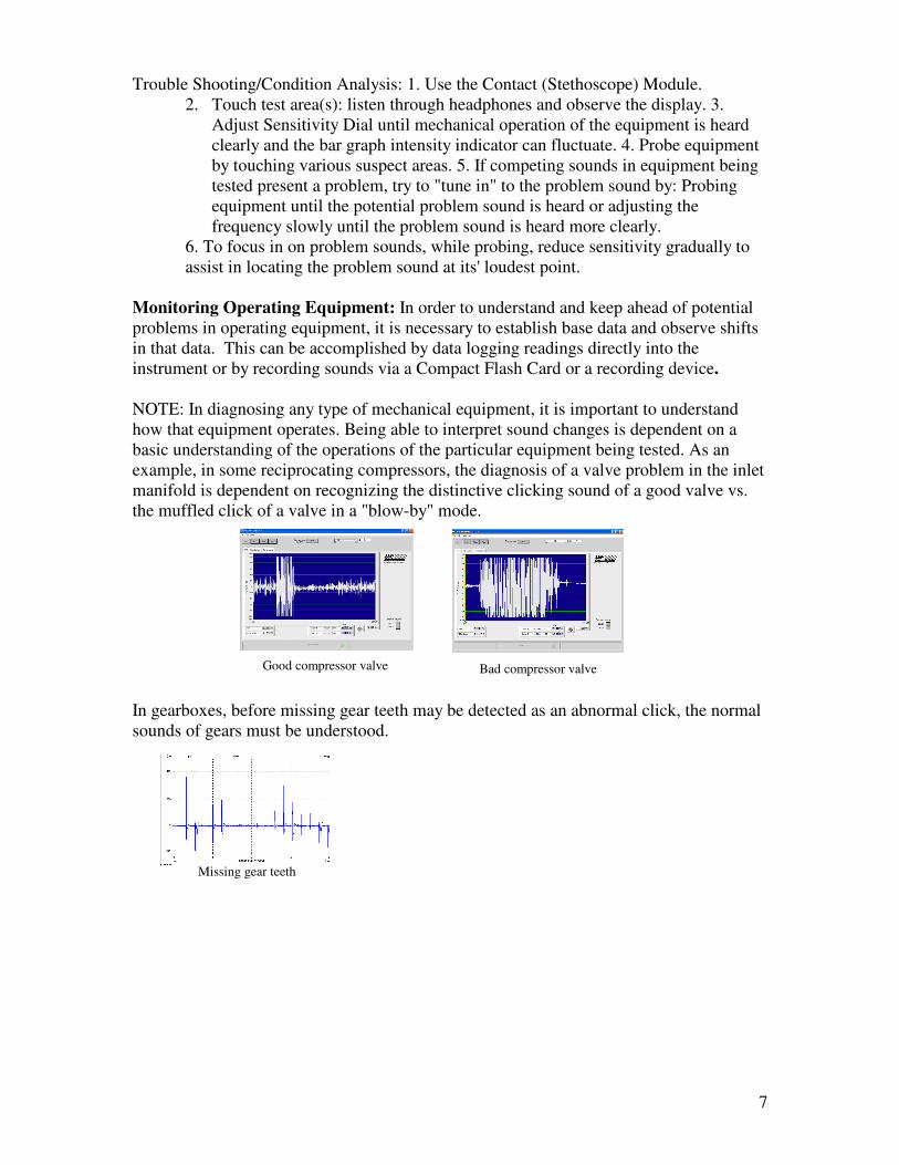
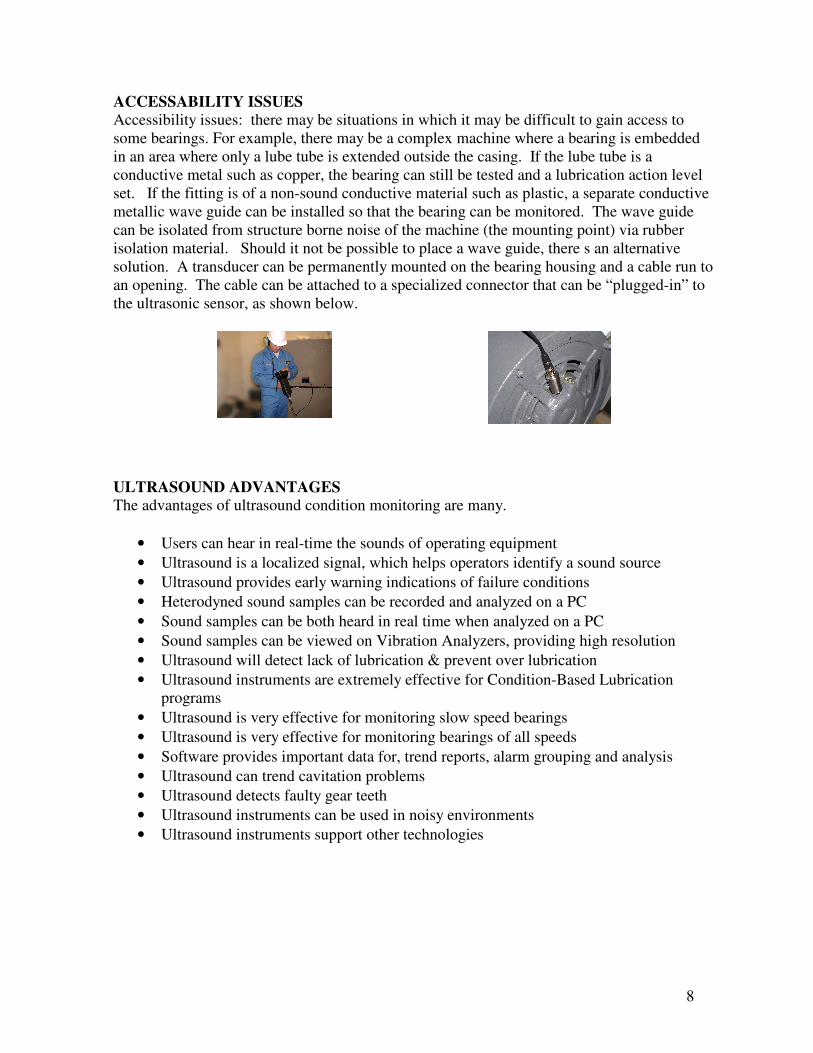
Monitoring Operating Equipment: In order to understand and keep ahead of potential problems in operating equipment, it is necessary to establish base data and observe shifts in that data. This can be accomplished by data logging readings directly into the instrument or by recording sounds via a Compact Flash Card or a recording device. NOTE: In diagnosing any type of mechanical equipment, it is important to understand how that equipment operates. Being able to interpret sound changes is dependent on a basic understanding of the operations of the particular equipment being tested. As an example, in some reciprocating compressors, the diagnosis of a valve problem in the inlet manifold is dependent on recognizing the distinctive clicking sound of a good valve vs. the muffled click of a valve in a "blow-by" mode. In gearboxes, before missing gear teeth may be detected as an abnormal click, the normal sounds of gears must be understood.
Good compressor valve Bad compressor valve
Missing gear teeth
8
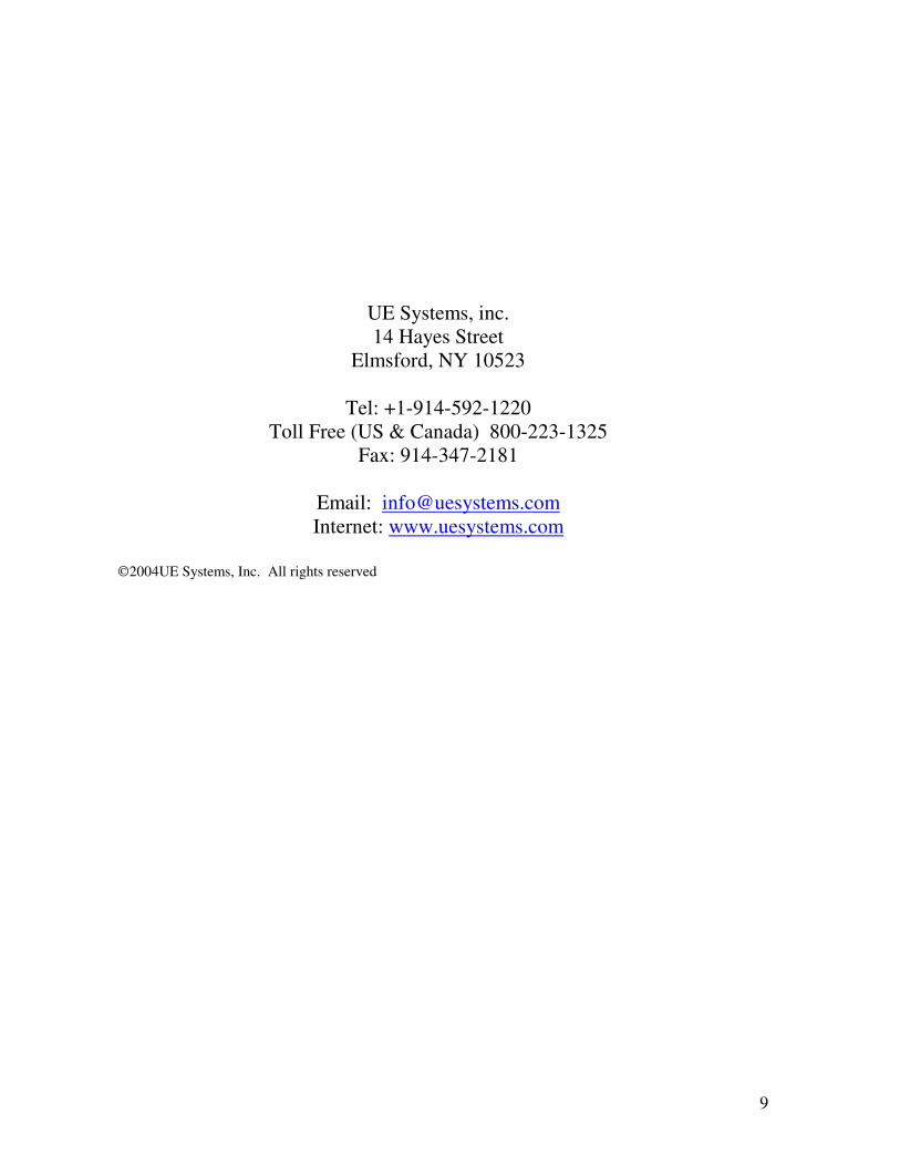
ACCESSABILITY ISSUES Accessibility issues: there may be situations in which it may be difficult to gain access to some bearings. For example, there may be a complex machine where a bearing is embedded in an area where only a lube tube is extended outside the casing. If the lube tube is a conductive metal such as copper, the bearing can still be tested and a lubrication action level set. If the fitting is of a non-sound conductive material such as plastic, a separate conductive metallic wave guide can be installed so that the bearing can be monitored. The wave guide can be isolated from structure borne noise of the machine (the mounting point) via rubber isolation material. Should it not be possible to place a wave guide, there s an alternative solution. A transducer can be permanently mounted on the bearing housing and a cable run to an opening. The cable can be attached to a specialized connector that can be “plugged-in” to the ultrasonic sensor, as shown below. ULTRASOUND ADVANTAGES The advantages of ultrasound condition monitoring are many.
• Users can hear in real-time the sounds of operating equipment • Ultrasound is a localized signal, which helps operators identify a sound source • Ultrasound provides early warning indications of failure conditions • Heterodyned sound samples can be recorded and analyzed on a PC • Sound samples can be both heard in real time when analyzed on a PC • Sound samples can be viewed on Vibration Analyzers, providing high resolution • Ultrasound will detect lack of lubrication & prevent over lubrication • Ultrasound instruments are extremely effective for Condition-Based Lubrication
programs • Ultrasound is very effective for monitoring slow speed bearings • Ultrasound is very effective for monitoring bearings of all speeds • Software provides important data for, trend reports, alarm grouping and analysis • Ultrasound can trend cavitation problems • Ultrasound detects faulty gear teeth • Ultrasound instruments can be used in noisy environments • Ultrasound instruments support other technologies
9
UE Systems, inc. 14 Hayes Street
Elmsford, NY 10523
Tel: +1-914-592-1220 Toll Free (US & Canada) 800-223-1325
Fax: 914-347-2181
Email: [email protected] Internet: www.uesystems.com
2004UE Systems, Inc. All rights reserved