Molten Steel Flow Control Technology for Decreasing Slab ... · ing and remain in the cast slab...
6
88 Copyright © 2017 JFE Steel Corporation. All Rights Reser ved. Abstract: In order to suppress defects entrapped in the solidi- fied shell in the continuous casting mold under high molten steel throughput conditions, the momentum of the molten steel in a mold with two static magnetic fields in the Flow Control Mold (FC mold) was investigated to evaluate the effects of the electromagnetic brake on the distribution of defects and unbalanced flow behavior. The main results are summarized as follows : (1) The measured value of the effect of the electromag- netic brake on decreasing the momentum of the mol- ten steel was consistent with the calculated value. Molten steel momentum could be reduced by more than 50% when the Stuart number was more than 3.5. (2) The position of entrapped defects in the solidified shell in the mold was influenced by throughput and the magnetic flux density of the electromagnetic brake. (3) Entrapped defects can be predicted by numerical simulation, which is useful for optimizing the mag- netic flux density and casting conditions. 1. Introduction In some cases, bubbles and inclusions which are entrapped in the solidified shell during continuous cast- ing and remain in the cast slab cause defects in the downstream hot rolling or cold rolling processes. Because both high quality and high productivity have been required in recent years, improvement of slab qual- ity in high speed, high throughput casting has become an issue. However, slab quality generally deteriorates in high speed, high throughput casting conditions in con- tinuous casting. Various causes have been pointed out, for example, the inclusion flotation effect in the mold is small due to the high casting speed, and as a result, inclusions tend to penetrate to the bottom of the mold 1) , and mold flux entrainment occurs due to the increased amount of fluctuation in the molten steel bath level at the meniscus due to the large discharge flow rate from the submerged entry nozzle (SEN) 2) . As a solution to these problems, it is possible to reduce the flow velocity of the molten steel discharged from the SEN by apply- ing electromagnetic brakes in the mold, which sup- presses penetration of inclusions to the bottom of the mold and fluctuations of the bath level at the meniscus 3) . When a two-hole SEN is used, deposits of inclusions such as alumina inside the nozzle or around the sliding gate can cause an unequal flow velocity from the nozzle. It is known that the flow of molten steel becomes unbal- anced in the opening-closing direction of the sliding gate (i.e., mold width direction or mold thickness direc- tion), and the degree of this unbalanced flow is particu- larly large under high throughput conditions 4–7) . The molten steel flow from the discharge holes of the two- hole SEN to the mold width direction collides with the solidified shell at the narrow mold faces and then branches and forms a rising flow and a descending flow. However, if an unbalanced flow occurs in the mold width direction, violent bath level undulations will occur in the meniscus area at the narrow mold faces in the region where the flow velocity of the rising flow turned from the collision area at the narrow face, and the increase in bath level fluctuations at the meniscus will cause entrainment of mold flux 8) . Moreover, inclusions which are carried to the bottom of the mold by the descending flow at the collision area at the narrow mold face are entrained toward the bottom of the mold, trapped on the solidified shell inside the strand, and become defects 9) . In the operational aspect, when a large unbalanced flow occurs in the mold, it is also thought that breakout occurs as a result of re-dissolution of the JFE TECHNICAL REPORT No. 22 (Mar. 2017) Molten Steel Flow Control Technology for Decreasing Slab Defects † FURUMAI Kohei *1 MIKI Yuji *2 † Originally published in JFE GIHO No. 38 (Aug. 2016), p. 36–41 *1 Senior Researcher Deputy Manager, Steelmaking Research Dept., Steel Res. Lab., JFE Steel *2 Dr. Eng., Principal Researcher Executive Assistant, Steel Res. Lab., JFE Steel
Transcript of Molten Steel Flow Control Technology for Decreasing Slab ... · ing and remain in the cast slab...

88Copyright © 2017 JFE Steel Corporation. All Rights Reserved.
Abstract:In order to suppress defects entrapped in the solidi-
fied shell in the continuous casting mold under high molten steel throughput conditions, the momentum of the molten steel in a mold with two static magnetic fields in the Flow Control Mold (FC mold) was investigated to evaluate the effects of the electromagnetic brake on the distribution of defects and unbalanced flow behavior. The main results are summarized as follows :(1) The measured value of the effect of the electromag-
netic brake on decreasing the momentum of the mol-ten steel was consistent with the calculated value. Molten steel momentum could be reduced by more than 50% when the Stuart number was more than 3.5.
(2) The position of entrapped defects in the solidified shell in the mold was influenced by throughput and the magnetic flux density of the electromagnetic brake.
(3) Entrapped defects can be predicted by numerical simulation, which is useful for optimizing the mag-netic flux density and casting conditions.
1. Introduction
In some cases, bubbles and inclusions which are entrapped in the solidified shell during continuous cast-ing and remain in the cast slab cause defects in the downstream hot rolling or cold rolling processes. Because both high quality and high productivity have been required in recent years, improvement of slab qual-ity in high speed, high throughput casting has become an issue. However, slab quality generally deteriorates in high speed, high throughput casting conditions in con-tinuous casting. Various causes have been pointed out, for example, the inclusion flotation effect in the mold is small due to the high casting speed, and as a result,
inclusions tend to penetrate to the bottom of the mold1), and mold flux entrainment occurs due to the increased amount of fluctuation in the molten steel bath level at the meniscus due to the large discharge flow rate from the submerged entry nozzle (SEN)2). As a solution to these problems, it is possible to reduce the flow velocity of the molten steel discharged from the SEN by apply-ing electromagnetic brakes in the mold, which sup-presses penetration of inclusions to the bottom of the mold and fluctuations of the bath level at the meniscus3). When a two-hole SEN is used, deposits of inclusions such as alumina inside the nozzle or around the sliding gate can cause an unequal flow velocity from the nozzle. It is known that the flow of molten steel becomes unbal-anced in the opening-closing direction of the sliding gate (i.e., mold width direction or mold thickness direc-tion), and the degree of this unbalanced flow is particu-larly large under high throughput conditions4–7). The molten steel flow from the discharge holes of the two-hole SEN to the mold width direction collides with the solidified shell at the narrow mold faces and then branches and forms a rising flow and a descending flow. However, if an unbalanced flow occurs in the mold width direction, violent bath level undulations will occur in the meniscus area at the narrow mold faces in the region where the flow velocity of the rising flow turned from the collision area at the narrow face, and the increase in bath level fluctuations at the meniscus will cause entrainment of mold flux8). Moreover, inclusions which are carried to the bottom of the mold by the descending flow at the collision area at the narrow mold face are entrained toward the bottom of the mold, trapped on the solidified shell inside the strand, and become defects9). In the operational aspect, when a large unbalanced flow occurs in the mold, it is also thought that breakout occurs as a result of re-dissolution of the
JFETECHNICALREPORTNo.22(Mar.2017)
Molten Steel Flow Control Technology for Decreasing Slab Defects†
FURUMAI Kohei*1 MIKI Yuji*2
† Originally published in JFE GIHO No. 38 (Aug. 2016), p. 36–41
*1 Senior Researcher Deputy Manager,Steelmaking Research Dept., Steel Res. Lab., JFE Steel
*2 Dr. Eng.,Principal Researcher Executive Assistant, Steel Res. Lab., JFE Steel
JFETECHNICALREPORTNo.22(Mar.2017) 89
Molten Steel Flow Control Technology for Decreasing Slab Defects
solidified shell in the collision area at the narrow mold face on the side with the larger discharge flow veloc-ity10). Considering these problems, reduction of molten steel momentum and suppression of unbalanced flows of molten steel in the casting mold are critical issues for satisfying both high productivity and high quality. Previ-ous research has examined various techniques for reduc-ing molten steel momentum and suppressing unbalanced flows in the mold by the geometry of the SEN, electro-magnetic stirring in the mold, and application of electro-magnetic brakes to the area of the SEN11–13). However, the details of the effect of the electromagnetic brake in reducing molten steel momentum in the mold, the corre-lation between the degree of unbalanced flow in the mold and the actual distribution of entrapped defects in slabs, and the influence of electromagnetic flow braking on unbalanced flows was not understood. In this report, the molten steel momentum and distribution of defects were measured in slabs cast by a continuous slab caster equipped with electromagnetic brakes with two stages at the upper and lower sections of the mold, and the effect of the electromagnetic brakes in reducing molten steel momentum and unbalanced flows, and the correlation between an unbalanced flow condition in the mold and the defect entrapment position in the mold were evalu-ated. The results of this research are described in the fol-lowing.
2. ExperimentalMethod
In this test, casting was performed with a continuous caster3) equipped with the FC (Flow Control) Mold, which makes it possible to apply electromagnetic brakes in the mold with coils positioned at the upper and lower sections of the mold. The test was performed under the conditions in Table1, which shows the casting speed, mold (slab) width and thickness, magnetic flux density of the FC Mold, and the chemical composition of the molten steel14). In order to evaluate the molten steel momentum reduction effect of the electromagnetic brake in the mold, the inclination of primary dendrites (angle of dendrites) in the direction perpendicular to the slab surface layer was measured, and molten steel flow velocity was calculated by Eq. (1)15). The solidification constant (2.58 × 10⁻³ m/s1/2) was calculated by Eq. (2) from the solidified shell thickness obtained from the dis-tribution of the sulfur (S) concentration in the slab after casting when an iron-sulfur alloy was added in the mold during actual casting. The solidification rate in Eq. (1) was obtained from the change over time in the solidified shell thickness shown by Eq. (3). In the investigation of the molten steel flow velocity, in order to measure the rising flow velocity after collision with the narrow mold faces, samples were cut from the narrow face side, pol-
ished, and etched with picric acid, after which the angle of dendrites was measured with a microscope at inter-vals of 1 mm.
D = K t = K Z/Vc ·· ········································· (1)
V =
dDdt ·························································· (2)
θ = ( 0.35 · C02
C02 + 0.0005
+ 0.65) · 11.5 · VF−0.177 ·
log ( 5.38 · 10−1 · VF2.08
V ) ······························ (3)
where, D: thickness of solidified shell [m], K: solidifica-tion constant [m/s1/2], t: time [s], Z: distance from menis-cus [m], Vc: casting velocity [m/s], θ: angle of dendrites [degree], C0: carbon concentration [mass%], VF: flow velocity of molten steel [m/s], and V: solidification rate [m/s].
For evaluation of the influence of the unbalanced flow in the mold on the distribution of defects, the dis-tribution of defects in the slab was measured by the ultrasonic defect detection method.
3. NumericalSimulationMethod
A numerical simulation was performed in order to consider the effect of the electromagnetic brakes on the flow velocity of molten steel in the mold16). The general-purpose fluid analysis program Fluent17) was used in the analysis, and a standard k-ε model18) was used as the turbulence model. The mass conservation equation, momentum conservation equation (Navier-Stokes equa-tion), energy conservation law, and enthalpy, which are included in Fluent, are shown in Eqs. (4)-(7), respec-tively.
∂∂t
ρv
( ) + — ⋅ ρv
v
( ) = −—p + — ⋅ μ—v
( ) ················· (4)
C Si Mn P Al
0.0015− 0.01− 0.15− 0.015− 0.025−0.0018 0.02 0.16 0.020 0.031
[mass%]
Table 1 Chemical composition of molten steel and casting conditions14)
Slab width [mm] 1600−1700
Slab thickness [mm] 260
Casting speed [m/min] 1.2−1.7
Throughput [t/min] 3.7−5.3
Index of magnetic flux density (T) 0.04−0.30

90 JFETECHNICALREPORTNo.22(Mar.2017)
Molten Steel Flow Control Technology for Decreasing Slab Defects
∂ρ∂t
+ — ⋅ ρv
( ) = 0 ················································ (5)
∂∂t
ρH( ) + — ⋅ ρv
H( ) = — ⋅ k—T( ) + S ···················· (6)
H = hr ef + Cp dTT r ef
T∫ +∂fL∂t
ΔH ························ (7)
where, ν: velocity [m/s], ρ: density of molten steel [kg/m3], p: pressure [Pa], μ: viscosity coefficient of mol-ten steel [0.0057 Pa · s]19), H: enthalpy [J], k: thermal conductivity [34 W · m/K]20), T: temperature [K], S: source term, href: reference enthalpy [J], Cp: specific heat at constant pressure [753 J · K/kg]21), Tref: reference tem-perature [K], and fL: liquid phase ratio.
For evaluation of the effect of the electromagnetic brakes, an external magnetic field B of a static magnetic field was set, and calculations were performed by using Eqs. (8) and (9).
J
= σ ( E
+V
+ B
) =1μ—× B
······························ (8)
∂B
∂t+ (v
⋅—)B
=1—2 B
+ (B
⋅—)v
σμ ··················· (9)
where, J: current density [A/m2], E: electric field [V/m], B: magnetic flux density [T], σ: electrical conductivity [7.14 × 10⁶ S/m] 22), and μ: magnetic permeability [1.26 × 10⁻⁶H/m] 23).
4. ExperimentalResultsandDiscussion
4.1 EffectofElectromagneticBrakesonMoltenSteelMomentum
Figure1 shows the influence of the magnetic flux density of the electromagnetic brake on the molten steel momentum in the mold14).
In this figure, the y-axis shows the ratio of the mea-sured momentum calculated from the angle of dendrites or the momentum obtained by numerical simulation, divided by the momentum in the case of no influence of the magnetic field, which was proposed by Imamura et al24). as expressed by Eqs. (10)-(14).
Vd = γ (1−ξ4)(1−ξ3) · 2g[c2(hTD + l1) + l2 + l3] ······· (10)
c = 0.364 q0.65 ················································ (11)
ξ3 = 1.1 (1−
aB’ )2
··········································· (12)
ξ4 = 1.16−0.015φ ··········································· (13)
ρVe = ρVd ( X6.3d )−1
········································· (14)
where, Vd: discharge flow rate from SEN [m/s], γ: ratio of maximum discharge flow velocity and average flow velocity of SEN, g: acceleration of gravity [m/s2], hTD: bath depth of tundish [m], l1: upper nozzle length [m], l2: lower nozzle length [m], l3: distance between lower nozzle and bath surface in SEN [m], c: discharge coeffi-cient in free fall flow in SEN, q: throughput [t/min], a: cross sectional area of flow falling in SEN [m2], B’: internal cross sectional area of SEN [m2], φ: discharge angle of SEN [degree], Ve: collision velocity on narrow mold face [m/s], X: average distance from discharge out-let of SEN to wall surface of mold [m], and d: diameter of SEN discharge outlet [m].
When the magnetic flux density is small, the momen-tum calculated by Eq. (14) with no influence of the mag-netic field is close to the value of measured momentum. In contrast, when the magnetic flux density is increased, causing a large electromagnetic brake action, it was found that the measured momentum becomes small, and the momentum of the molten steel can be reduced by a maximum of approximately one-half in comparison with the case in which the electromagnetic brake is not applied. Looking at the ratio of the momentum obtained by numerical simulation to the momentum given by Eq. (14), with the throughputs of both 4.7 t/min and 5.3 t/min, there were deviations when the magnetic flux den-sity was small, but good agreement was found between the values given by Eq. (14) and the measured values. Moreover, the Stuart number N, which is an index giv-ing the influence of a magnetic field, is given by the ratio of an external force term and an inertial force term, as shown in Eq. (15)23).
Fig. 1 Relationship between magnetic flux density and ratio of measured or calculated molten steel momentum in mold to momentum calculated by eq.(14)14)
JFETECHNICALREPORTNo.22(Mar.2017) 91
Molten Steel Flow Control Technology for Decreasing Slab Defects
N =|σ (v
× B
) × B
|| ρ (v
⋅—)v
|=B 2σLρv ························· (15)
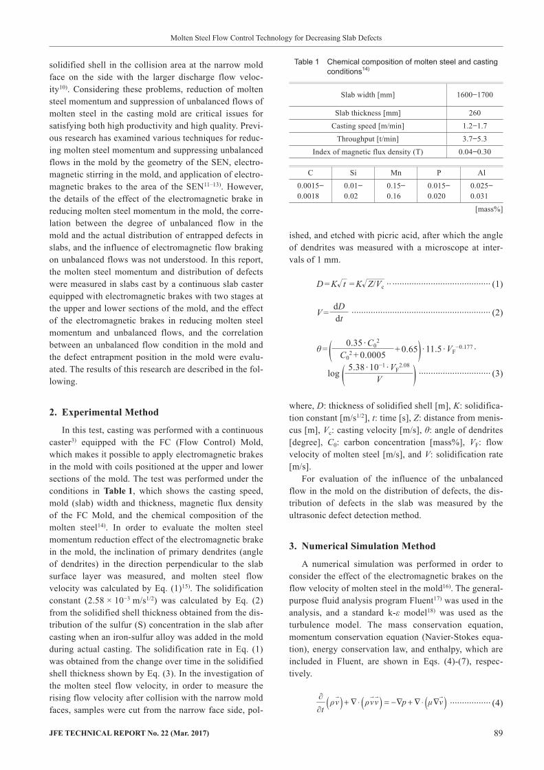
where, L: representative length [m].Figure2 shows the relationship between the Stuart
number N and the ratio of the measured value or numeri-cal simulation value of momentum to the momentum given by Eq. (14)14). It can be understood that there is a correlation between the Stuart number N and the ratio of the measured or calculated momentum to the momentum given by Eq. (14), and the momentum reduction effect by the electromagnetic brakes in the mold increases as the Stuart number N becomes larger. From these results, it is considered that the molten steel momentum in the mold can be reduced by approximately 50% in compari-son with the case of no electromagnetic brake if a mag-netic flux density at which the Stuart number N is larger than approximately 3.5 is applied, even under different conditions of throughput and magnetic flux density.
4.2 UnbalancedFlowinMold
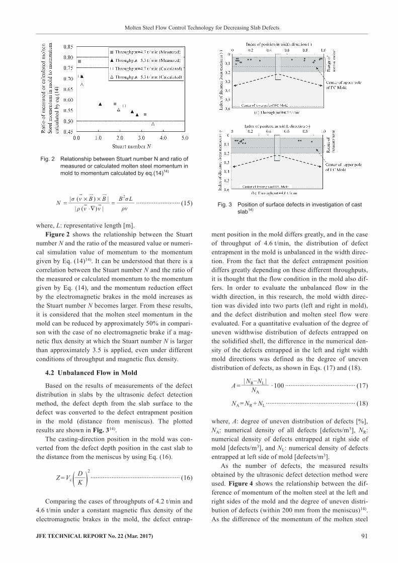
Based on the results of measurements of the defect distribution in slabs by the ultrasonic defect detection method, the defect depth from the slab surface to the defect was converted to the defect entrapment position in the mold (distance from meniscus). The plotted results are shown in Fig.314).
The casting-direction position in the mold was con-verted from the defect depth position in the cast slab to the distance from the meniscus by using Eq. (16).
Z = Vc ( DK )2
··················································· (16)
Comparing the cases of throughputs of 4.2 t/min and 4.6 t/min under a constant magnetic flux density of the electromagnetic brakes in the mold, the defect entrap-
ment position in the mold differs greatly, and in the case of throughput of 4.6 t/min, the distribution of defect entrapment in the mold is unbalanced in the width direc-tion. From the fact that the defect entrapment position differs greatly depending on these different throughputs, it is thought that the flow condition in the mold also dif-fers. In order to evaluate the unbalanced flow in the width direction, in this research, the mold width direc-tion was divided into two parts (left and right in mold), and the defect distribution and molten steel flow were evaluated. For a quantitative evaluation of the degree of uneven widthwise distribution of defects entrapped on the solidified shell, the difference in the numerical den-sity of the defects entrapped in the left and right width mold directions was defined as the degree of uneven distribution of defects, as shown in Eqs. (17) and (18).
A = · 100 ········································ (17)
NA = NR + NL ··················································· (18)
where, A: degree of uneven distribution of defects [%], NA: numerical density of all defects [defects/m3], NR: numerical density of defects entrapped at right side of mold [defects/m3], and NL: numerical density of defects entrapped at left side of mold [defects/m3].
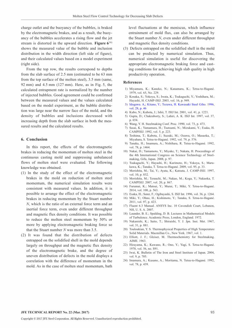
As the number of defects, the measured results obtained by the ultrasonic defect detection method were used. Figure4 shows the relationship between the dif-ference of momentum of the molten steel at the left and right sides of the mold and the degree of uneven distri-bution of defects (within 200 mm from the meniscus)14). As the difference of the momentum of the molten steel
| NR−NL |NA
Fig. 2 Relationship between Stuart number N and ratio of measured or calculated molten steel momentum in mold to momentum calculated by eq.(14)14)
Fig. 3 Position of surface defects in investigation of cast slab14)

92 JFETECHNICALREPORTNo.22(Mar.2017)
Molten Steel Flow Control Technology for Decreasing Slab Defects
the casting conditions in a continuous casting process. Figure516) shows an example of a calculation of the dis-tribution of entrapped bubbles with diameters of 0.5 mm in the center of thickness and at the liquid-solid interface (solidification interface, solid phase ratio fs=0.2). The upper part of the figure shows the bubble distribution in the center of thickness, and the lower part shows the bubble entrapment ratio at the solidification interface. Here, the calculated entrapment ratio was normalized by the concentration of injected bubbles.
The left and right sides of the figure show the results when the magnetic flux density of the FC Mold was 0.1 T and 0.2 T, respectively. When the intensity of the mag-netic flux density of the FC Mold is large (field inten-sity: 0.2 T), flotation of bubbles mixed in the jet stream of the nozzle is accelerated. This is thought to be because the nozzle jet stream, which is determined by the flow velocity of the molten steel from the nozzle dis-
in the mold became larger, the degree of uneven distri-bution of defects also increased, and the distribution of defects in the mold was influenced greatly by the momentum of the molten steel. Thus, in suppressing the degree of uneven distribution of defects in the mold, reducing the molten steel momentum in the mold is important, and reducing the molten steel momentum by applying an appropriate electromagnetic braking force corresponding to throughput, which can be arranged by the Stuart numberN, is considered to be effective.
5. ExampleofNumericalSimulationinContinuousCastingProcessThis chapter presents an example of a numerical
simulation which was used in a study of optimization of
Fig. 4 Relationship between difference of momentum of rising flow at left and right mold narrow sides and degree of unbalanced distribution of defects14)
Fig. 5 Calculated results of entrapped bubble concentration16)
Fig. 6 Comparison between calculated and measured bubble concentration16)
JFETECHNICALREPORTNo.22(Mar.2017) 93
Molten Steel Flow Control Technology for Decreasing Slab Defects
Copyright © 2017 JFE Steel Corporation. All Rights Reserved. Unauthorized reproduction prohibited.
level fluctuations at the meniscus, which influence entrainment of mold flux, can also be arranged by the Stuart number N, even under different throughput and magnetic flux density conditions.
(3) Defects entrapped on the solidified shell in the mold can be predicted by numerical simulation. Thus, numerical simulation is useful for discovering the appropriate electromagnetic braking force and cast-ing conditions for achieving high slab quality in high productivity operation.
References 1) Miyamura, K.; Kaneko, N.; Kanamaru, K.; Tetsu-to-Hagané.
1979, vol. 65, No. 229. 2) Kosaka, S.; Yokoya, S.; Iwata, K.; Tsukaguchi, Y.; Yoshihara, M.;
Hayashi, H. CAMP-ISIJ. 2003, vol. 16, p. 949. 3) Idogawa. A,; Kitano, Y.; Tozawa, H. Kawasaki Steel Giho. 1996,
vol. 28, p. 46 4) Kubo, N.; Kubota, J.; Ishii, T. ISIJ Int. 2001, vol. 41, p. 1221. 5) Gupta, D.; Chakraborty, S.; Lahiri, A. K. ISIJ Int. 1997, vol. 37,
p. 654. 6) Wang, Y. H. Steelmaking Conf. Proc. 1990, vol. 73, p. 473. 7) Sasai, K.; Yamamura, H.; Tsutsumi, N.; Mizukami, Y.; Esaka, H.
CAMPISIJ. 1992, vol. 5, p. 223. 8) Teshima, T.; Kubota, J.; Suzuki, M.; Ozawa, O.; Masaoka, T.;
Miyahara, S. Tetsu-to-Hagané. 1992, vol. 79, p. 576. 9) Tanaka, H.; Imamura, A.; Nishihara, R. Tetsu-to-Hagané. 1992,
vol. 78, p. 1464.10) Nakai, D.; Yamamoto, Y.; Miyake, T.; Nakata, H. Proceedings of
the 4th International Congress on Science Technology of Steel-making, Gifu, Japan. 2008, p. 97.
11) Tsukaguchi, Y.; Hayashi, H.; Kurimoto, H.; Yokoya, S.; Maru-kawa, K.; Tanaka, T. Tetsu-to-Hagané. 2009, vol. 95, p. 33.
12) Morishita, M.; Tai, Y.; Ayata, K.; Katsuta, J. CAMP-ISIJ. 1997, vol. 10, p. 832.
13) Morishita, M.; Terauchi, M.; Nakao, M.; Koga, Y.; Nakaoka, T. CAMPISIJ. 2007, vol. 20, p. 867.
14) Furumai, K.; Matsui, Y.; Murai, T.; Miki, Y. Tetsu-to-Hagané. 2014, vol. 100, p. 563.
15) Esaka, H.; Suter, F.; Ogibayashi, S. ISIJ Int. 1996, vol. 36, p. 1264.16) Miki, Y.; Ohno, H.; Kishimoto, Y.; Tanaka, S. Tetsu-to-Hagané.
2011, vol. 97, p. 423.17) Fluent 6.3 Manual. ANSYS Inc. 10 Cavendish Court, Lebanon,
NH, U. S. A. 2007.18) Launder, B. E.; Spalding, D. B. Lectures in Mathematical Models
of Turbulence. Academic Press, London, England. 1972.19) Nakanishi, K.; Saito, T.; Shiraishi, Y. J. Jpn. Inst. Met. 1967,
vol. 31, p. 881.20) Touloukian, Y. S. Thermophysical Properties of High Temperature
Solid Materials. Macmillan Co., New York. 1967, vol. 1.21) Elliott, J. F.; Gleiser, M. Thermochemistry for Steelmaking.
AIME. 1963.22) Hirayama, K.; Kuwano, R.; Ono, Y.; Yagi, S. Tetsu-to-Hagané.
1970, vol. 56, no. S91.23) Iwai, K. Bulletin of The Iron and Steel Institute of Japan. 2004,
vol. 9, p. 705.24) Imamura, A.; Kusano, A.; Moritama, N. Tetsu-to-Hagané. 1992,
vol. 78, p. 439.
charge outlet and the buoyancy of the bubbles, is braked by the electromagnetic brakes, and as a result, the buoy-ancy of the bubbles accelerates a rising flow and the jet stream is distorted in the upward direction. Figure616) shows the measured value of the bubble and inclusion distribution in the width direction (left side of figure), and their calculated values based on a model experiment (right side).
From the top row, the results correspond to depths from the slab surface of 2.5 mm (estimated to be 63 mm from the top surface of the molten steel), 3.5 mm (same, 92 mm) and 4.5 mm (127 mm). Here, as in Fig. 5, the calculated entrapment rate is normalized by the number of injected bubbles. Good agreement could be confirmed between the measured values and the values calculated based on the model experiment, as the bubble distribu-tion was large near the narrow face of the mold, and the density of bubbles and inclusions decreased with increasing depth from the slab surface in both the mea-sured results and the calculated results.
6. Conclusion
In this report, the effects of the electromagnetic brakes in reducing the momentum of molten steel in the continuous casting mold and suppressing unbalanced flows of molten steel were evaluated. The following knowledge was obtained.(1) In the study of the effect of the electromagnetic
brakes in the mold on reduction of molten steel momentum, the numerical simulation results were consistent with measured values. In addition, it is possible to arrange the effect of the electromagnetic brakes in reducing momentum by the Stuart number N, which is the ratio of an external force term and an inertial force term, even under different throughput and magnetic flux density conditions. It was possible to reduce the molten steel momentum by 50% or more by applying electromagnetic braking force so that the Stuart number N was more than 3.5.
(2) It was found that the distribution of defects entrapped on the solidified shell in the mold depends largely on throughput and the magnetic flux density of the electromagnetic brake, and the degree of uneven distribution of defects in the mold displays a correlation with the difference of momentum in the mold. As in the case of molten steel momentum, bath