Molecular Modeling as an Enabling Tool in Advanced...
25
Molecular Modeling as an Enabling Tool in Advanced Material Research Luke E. K. Achenie, Professor Virginia Polytechnic Institute and State University Chemical Engineering Department NSF (US/China) Workshop – March 2014 1
Transcript of Molecular Modeling as an Enabling Tool in Advanced...

Molecular Modeling as an Enabling Tool in Advanced Material Research
Luke E. K. Achenie, Professor
Virginia Polytechnic Institute and State University
Chemical Engineering Department
NSF (US/China) Workshop – March 2014
1

Outline
Computational Science
Process Flexibility & Design
Oral Drug Delivery
Membrane/CVD Research
Molecular Modeling
2

Support (alumina, stainless steel)
Intermediate layer (alumina)Selective layer (silica, palladium)
With Oyama Group – Molecular Dynamics Study(Hybrid Inorganic / Organic membranes)
3
inorganic membrane
Membrane separation -- wide use in natural gas processing
4
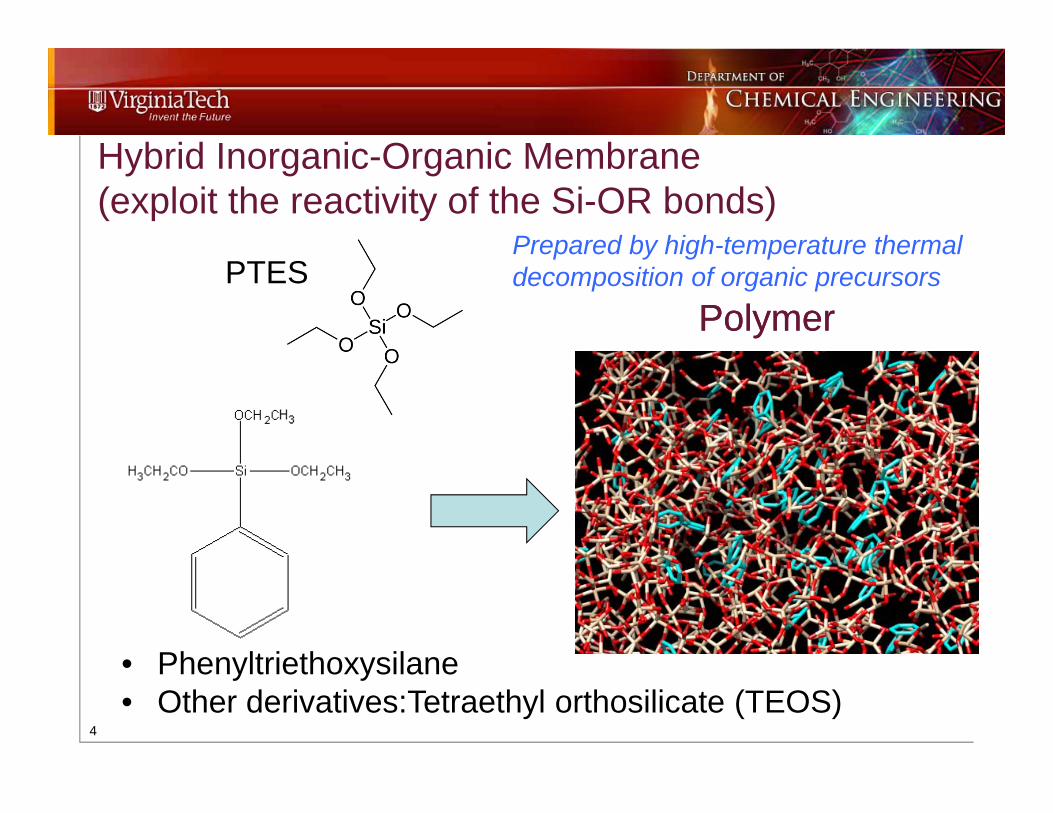
• Phenyltriethoxysilane• Other derivatives:Tetraethyl orthosilicate (TEOS)
Hybrid Inorganic-Organic Membrane (exploit the reactivity of the Si-OR bonds)
Prepared by high-temperature thermal decomposition of organic precursors
Polymer Polymer PTES
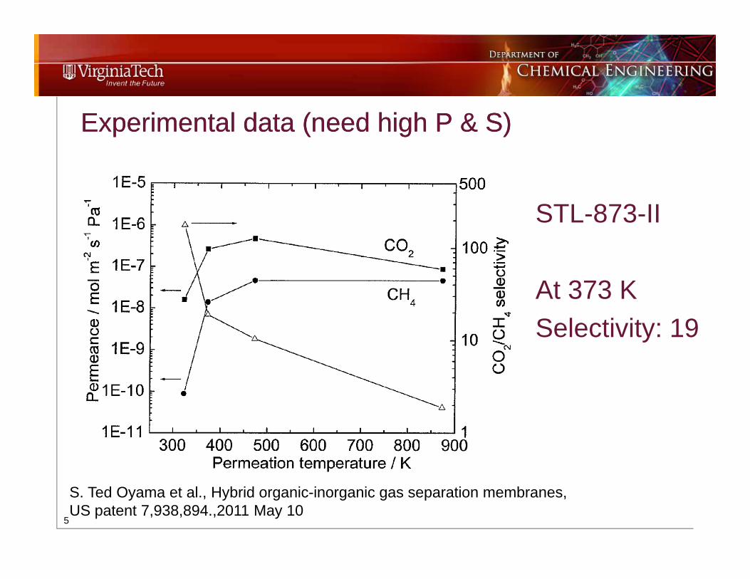
Experimental data (need high P & S)Experimental data (need high P & S)
5
STL-873-II
At 373 KSelectivity: 19
S. Ted Oyama et al., Hybrid organic-inorganic gas separation membranes, US patent 7,938,894.,2011 May 10

Two Specific Aims
6
1. Construct Inorganic/Organic Membrane by MD2. Simulate Separation of CO2/CH4 by MD

AIM1-- Membrane Structure: Pore Creation and Insertion of Phenyl Groups - Zhenxing Wang, Luke E.K. Achenie, Sheima Jativ Khativa and S. Ted Oyama, “Simulation study of carbon dioxide and methane gas permeation in hybrid organic-inorganic membrane,” Journal of Membrane Science., 387/388, 30–39, 2012.
AIM1-- Membrane Structure: Pore Creation and Insertion of Phenyl Groups - Zhenxing Wang, Luke E.K. Achenie, Sheima Jativ Khativa and S. Ted Oyama, “Simulation study of carbon dioxide and methane gas permeation in hybrid organic-inorganic membrane,” Journal of Membrane Science., 387/388, 30–39, 2012.
7
#1 4.60 Å #2 5.22 Å #3 11.23 Å #4 11.93 Å#1 4.60 Å #2 5.22 Å #3 11.23 Å #4 11.93 Å
#1-1#1-1 #2-1#2-1 #3-2#3-2 #4-2#4-2

AIM 1 –Phenyl Group & Partial Charge Effects – Initial MDAIM 1 –Phenyl Group & Partial Charge Effects – Initial MD
8
CO2(mol m-2 s-1 Pa-1)
CH4(mol m-2 s-1 Pa-1) Selectivity
No Phenyl GroupsNo Charge 1.97×10⁻⁴ 6.66×10⁻⁴ 0.30
7Phenyl GroupsNo Charge 6.62×10⁻⁵ 2.52×10⁻⁵ 2.63
7 Phenyl GroupsPartial Charge 1.18×10⁻⁴ 1.64×10⁻⁶ 71.95

9
AIM 2: Gas Permeation• P=2 MPa T=373 K • NVT & NPT • Dreiding force field
AIM 2: Gas Permeation• P=2 MPa T=373 K • NVT & NPT • Dreiding force field
Gas region54 ÅGas region54 Å
- Zhenxing Wang, Luke E.K. Achenie, Sheima Jativ Khativa and S. Ted Oyama, “Simulation study of carbon dioxide and methane gas permeation in hybrid organic-inorganic membrane,” Journal of Membrane Science., 387/388, 30–39, 2012.
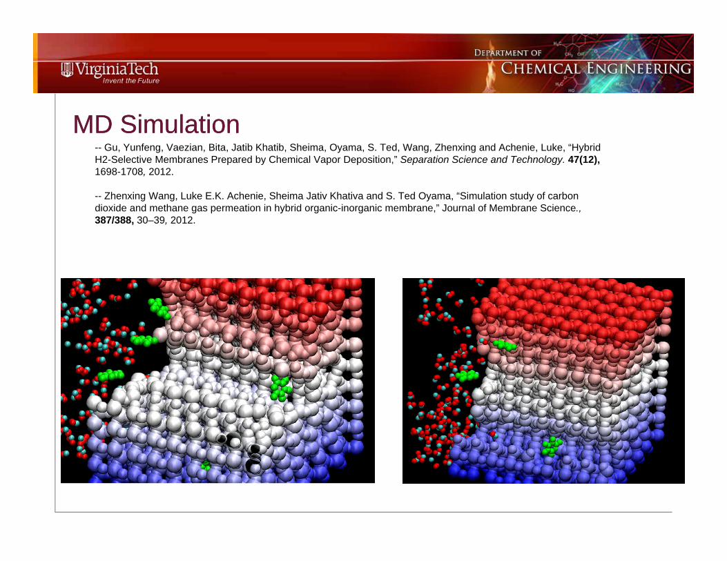
MD SimulationMD Simulation-- Gu, Yunfeng, Vaezian, Bita, Jatib Khatib, Sheima, Oyama, S. Ted, Wang, Zhenxing and Achenie, Luke, “Hybrid H2-Selective Membranes Prepared by Chemical Vapor Deposition,” Separation Science and Technology. 47(12), 1698-1708, 2012.
-- Zhenxing Wang, Luke E.K. Achenie, Sheima Jativ Khativa and S. Ted Oyama, “Simulation study of carbon dioxide and methane gas permeation in hybrid organic-inorganic membrane,” Journal of Membrane Science., 387/388, 30–39, 2012.
11
Molecular dynamics studyMolecular dynamics study
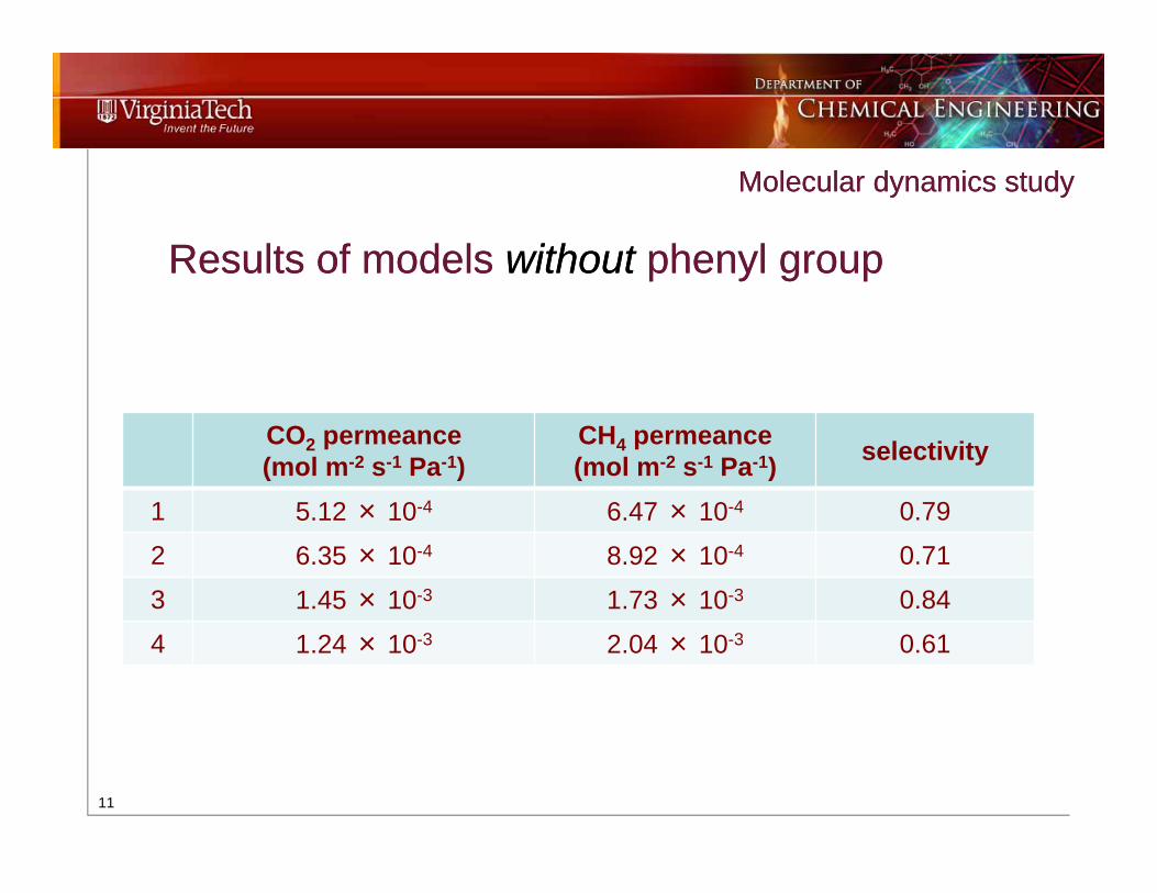
Results of models without phenyl groupResults of models without phenyl group
CO2 permeance(mol m-2 s-1 Pa-1)
CH4 permeance(mol m-2 s-1 Pa-1) selectivity
1 5.12 × 10⁻⁴ 6.47 × 10⁻⁴ 0.79
2 6.35 × 10⁻⁴ 8.92 × 10⁻⁴ 0.71
3 1.45 × 10⁻³ 1.73 × 10⁻³ 0.84
4 1.24 × 10⁻³ 2.04 × 10⁻³ 0.61

12
Molecular dynamics studyMolecular dynamics study
Permeance of models with phenyl groupPermeance of models with phenyl group
# PhGrps
CO2permeance(mol m-2 s-1
Pa-1)
CH4 permeance(mol m-2 s-1 Pa-1) selectivity
O4.0-1 1 2.87 × 10-
4 1.66 × 10⁻⁵ 17.3
O4.0-2 2 1.20 × 10⁻⁴ 3.88 × 10⁻⁶ -
S 5.0-2 2 1.14 × 10⁻³ 8.53 × 10⁻⁴ 1.34
S 5.0-4 4 1.10× 10⁻³ 5.33 × 10⁻⁴ 2.06
S 5.3-2 2 1.12 × 10⁻³ 1.06 × 10⁻³ 1.06
S 5.3-4 4 1.16 × 10⁻³ 1.27 × 10⁻³ 0.91Compare with Selectivity of 19 from Expts.

13
2nd Modeling Approach – Mixed Mechanisms2nd Modeling Approach – Mixed Mechanisms

14
Mixed Mechanism Diffusion ModelMixed Mechanism Diffusion Model
Micro-structure # 1
Micro-structure # 2
-- Zhenxing Wang, Luke E.K. Achenie, Sheima J. Khatib, and S. Ted Oyama (2013), “Mixed mechanism model for permeation of gases in hybrid inorganic-organic membranes,” Ind. Eng. Chem. Res., 52, 3258–3265, 2013.

15
Some ResultsSome Results -- Zhenxing Wang, Luke E.K. Achenie, Sheima J. Khatib, and S. Ted Oyama (2013), “Mixed mechanism model for permeation of gases in hybrid inorganic-organic membranes,” Ind. Eng. Chem. Res., 52, 3258–3265, 2013.

Zinc SulfideZinc Sulfide
16
Application: •Used in the semiconductor industry to produce thin films on wafer substrate•Reflective window•Laser dooms•Nano sensors•Blue light diodes•Luminescent displays•Infra-red devices(anti reflection coating)
1. T, Matsuoka, A. Ohki, T. Ohno, and Y.Kawaguchi, J. Cryst. Growth 138, 727, 1994.
Multi-Scale modeling of chemical vapor deposition processesMulti-Scale modeling of chemical vapor deposition processes

CVD of Zinc SulfideCVD of Zinc Sulfide
17
2 2( ) ( ) ( )Zn g H S ZnS g H g Gas phase reactionSurface reactions ( ) ( )Z n S g Z n S s
Substrate H2S+Zn+Ar Outflow

Gas Phase reaction mechanism (ZnS) via DFT Molecular ModelingGas Phase reaction mechanism (ZnS) via DFT Molecular Modeling
18
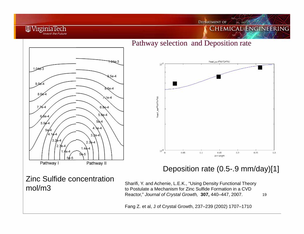
Pathway selection and Deposition ratePathway selection and Deposition rate
19
Zinc Sulfide concentration mol/m3
Deposition rate (0.5-.9 mm/day)[1]
Fang Z. et al, J of Crystal Growth, 237–239 (2002) 1707–1710
Sharifi, Y. and Achenie, L.E.K., “Using Density Functional Theory to Postulate a Mechanism for Zinc Sulfide Formation in a CVD Reactor,” Journal of Crystal Growth, 307, 440–447, 2007.

Effect of substrate geometry on deposition rateEffect of substrate geometry on deposition rate
20
Sharifi, Y. and Achenie, L.E.K. “Effect of substrate geometry on deposition rate in CVD,” Journal of Crystal Growth, 304, 520–525, 2007.
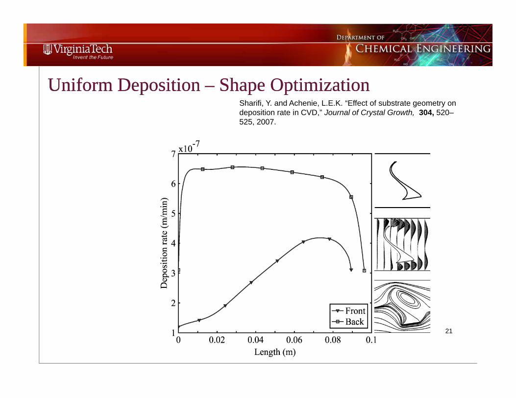
Uniform Deposition – Shape Optimization Uniform Deposition – Shape Optimization
21
Sharifi, Y. and Achenie, L.E.K. “Effect of substrate geometry on deposition rate in CVD,” Journal of Crystal Growth, 304, 520–525, 2007.
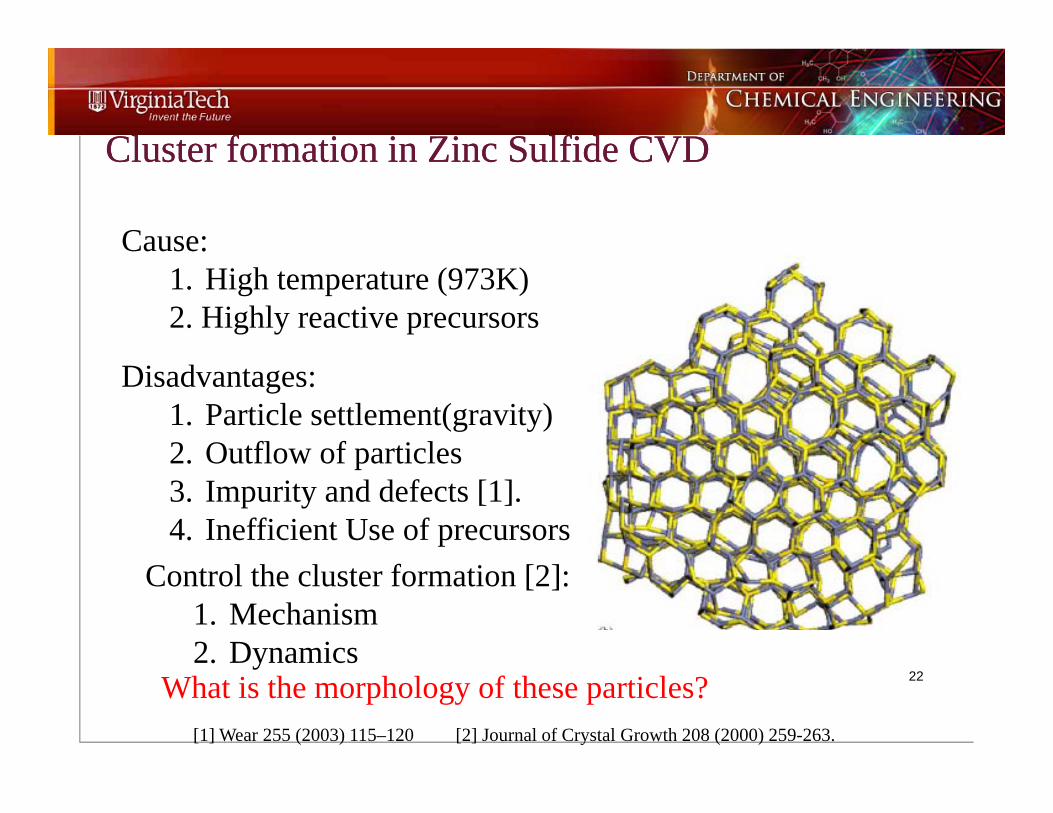
Cluster formation in Zinc Sulfide CVDCluster formation in Zinc Sulfide CVD
22
Cause: 1. High temperature (973K)2. Highly reactive precursors
Disadvantages:1. Particle settlement(gravity)2. Outflow of particles3. Impurity and defects [1].4. Inefficient Use of precursors
Control the cluster formation [2]:1. Mechanism2. Dynamics
What is the morphology of these particles? [1] Wear 255 (2003) 115–120 [2] Journal of Crystal Growth 208 (2000) 259-263.
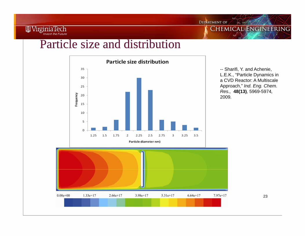
Particle size and distributionParticle size and distribution
23
-- Sharifi, Y. and Achenie, L.E.K., “Particle Dynamics in a CVD Reactor: A MultiscaleApproach,” Ind. Eng. Chem. Res., 48(13), 5969-5974, 2009.

Summary
Molecular Modeling as an Enabling Tool in Advanced Material Research

25
Acknowledgements:
• Funding from NSF, DOE
• Graduate Students
Thank You !!