Molecular dynamics study of the relative sliding ...Molecular dynamics study of the relative sliding...
8
α 0.05 %
Transcript of Molecular dynamics study of the relative sliding ...Molecular dynamics study of the relative sliding...

Molecular dynamics study of the relative sliding mechanisms in amorphous silica
Molecular dynamics study of the relative slidingmechanisms in amorphous silica
Anton Yu. Nikonov, Andrey I. Dmitriev, Werner �Osterle
anickono�@ispms.ru
Abstract
In the paper simulation of the treatment of two crystals with amorphousinterlayer was carried out using the method of molecular dynamics. We studieda α-silica (quartz) sample with amorphous interlayer. The simulation resultrevealed several processes realized in the contact area as a result of shearloading. Depending on the temperature of the sample we observed deformationof an amorphous layer and formation of wear particles. It has been found thata necessary condition for the formation of wear particles is the presence offree volume in the interface. We compare the time dependencies of resistanceforces for all samples. Results of simulation allows us to explain the low frictionproperties of silica tribo�lm and also to say about silica amorphous layer as asolid lubricant.
1 Introduction
Carbon �bers and silica nanoparticles (SNPs) are widely used in all kinds of polymermatrix composites (PMCs) either reclusively or in combination. Compared to un-�lled polymers, �ber-reinforced PMCs provide higher strength and wear resistance[1]. On the other hand, a number of interesting material properties were achievedby adding silica nano-particles (SNPs) to polymer materials [2]. Considering tribo-logical properties, studies described in [3, 4] have shown that the application �eldof PMCs with micron-sized functional �llers can be extended by additionally in-corporating a small fraction of inorganic nanoparticles. Especially SNPs are verye�ective in this respect, and it was shown that only 0.05 vol.% SNPs was enough toexert a measurable e�ect on friction evolution [5]. In the following, the compositecontaining micro- and nano�llers will be termed as hybrid composite whereas itscounterpart without nanoparticles will be termed conventional composite.The key for obtaining a better understanding of dry sliding properties of a tribologi-cal couple is a thorough investigation of the third body �lms, also termed tribo�lms,forming at the tribological interface. The concept of a third body layer being re-sponsible for load transfer and velocity accommodation between the �rst bodies ofa tribological couple was �rst introduced by Godet [6]. Especially, antifriction andantiwear properties, i.e. a low coe�cient of friction and wear rate, usually can beattributed to the formation of stable tribo�lms [7]. During our own previous studies
337

Proceedings of XLIV International Summer School � Conference APM 2016
we have shown that e�ective tribo�lms, formed during automotive braking, consistof structural features on the nanometer scale [8]. Furthermore, we could simulate thesliding behavior of such �lms by nanoscale modeling. Since silica-based tribo�lmsare most crucial for providing wear protection and low friction, it was of great inter-est to simulate their sliding behavior. So the objective of this paper was to study thesliding behavior of silica tribo�lm in order to understand the low friction propertiesof hybrid composites.
2 Materials
The raw materials used for preparation of the EP + 5% SiO2 composite were: astandard diglycidil ether of bisphenol A (DBEBA) o�ered by DOW as DER331,a cycloaliphatic amine hardener HY 2954 from Huntsman and a colloidal silicamasterbatch with a concentration of 40 mass% and a nominal particle diameter of20 nm in DGBEBA o�ered as Nanopox F400 from Evonik. A thin slice was preparedfrom the EP + 5% SiO2 composite by microtomy and investigated in a ScanningTransmission Electron Microscope (STEM) of type JEOL 2200FS.
3 Experimental Data
Figure 1: Friction coe�cient as func-tion of pv for composites with 5%silica nanoparticles (hybrid) and forthe conventional composite withoutSNPs.
Striking di�erences were observed betweenthe tribological performance of conven-tional and hybrid composites at certainstressing conditions, as shown in Fig. 1.Friction is almost the same at pv-valueslower than 1 MPa m/s. Then a steepincrease is observed for the conventionalcomposite. It should be mentioned herethat the bene�cial e�ect of the SNPs isonly observed in combination with the car-bon �bers. Composites consisting solely ofEP and SNP do not provide low friction athigh pv, and furthermore, wear is not re-duced to the same extend as for the hybrid
composite [4].
4 An overview of previous results
Details of modelling of tribo�lm sliding behavior have been described in our recentpaper [9]. The size of modelling elements was adjusted to 10 nm which is closeto the size of the nano�ller of the polymer matrix composite (20 nm) and also iswell suited for sliding simulations of 100 nm thick tribo�lms, as demonstrated inprevious studies [8, 10]. The method of Movable Cellular Automata (MCA) wasused for sliding simulations [9]. It was expected that the results of these simulationsmay enable us to understand the very low friction coe�cient observed for the hybrid
338

Molecular dynamics study of the relative sliding mechanisms in amorphous silica
composite at pv = 24 MPa m/s. Unfortunately, this was not the case. Despiteof a very well developed mechanically mixed layer and smooth sliding simulationthe friction coe�cient of tribo�lms did not drop below 0.2 [10], whereas 0.06 wasmeasured for the hybrid composite at pv = 24 MPa m/s.The result shown in Fig. 2 is only one example of a comprehensive parameter studyof the silica-graphite system. Brie�y, the following trends were observed duringthis study: decreasing the graphite content to 6% increases the COF �uctuationssigni�cantly and the mean COF slightly. The same e�ect was observed for thestructure with 10% graphite if the normal pressure was reduced from 130 to 70 MPa.On the other hand, an increase from 130 to 150 MPa made no di�erence. In orderto �nd conditions of smooth sliding we identi�ed the parameters given in Fig. 2 asan optimum for the silica �lm with 10% graphite inclusions.
Figure 2: a) Structure formation and b) friction evolution during sliding simulationof a tribo�lm consisting of 10% graphite (black) and 90% silica (orange) supportedby carbon �ber (violet) and steel (green). External parameters: p = 130 MPa, v =10 m/s.
A possible explanation of this very low friction coe�cient could be assigned withsilica transition to amorphous state. Another study even suggests amorphizationof graphite being responsible for friction reduction [11]. Since we have found nomeans for considering such mechanisms in our model, the observed superlubricitye�ect could not be explained by the MCA method. E�ort of �nding explanation byMolecular Dynamics (MD) simulation was done in this work.
5 A model description
Since amorphous silicon oxide played a crucial role in the present study, we made anattempt to study its sliding behavior. The �rst step comprised of building a sampleby linking SiO4 tetrahedrons to form the appropriate crystal structure. Then anintermediate layer of this crystal sample was transformed to the amorphous state byvirtual heating beyond the melting temperature and subsequent quenching. Next,the sliding behavior of the samples was studied while tangential and normal forcesand a sliding velocity were applied to the rigid substrates comprising of crystallineSiO2.
339

Proceedings of XLIV International Summer School � Conference APM 2016
Figure 3: Initial structure of themodeled sample and a loadedscheme.
A modeled sample with two crystalline parts(on the top (block 1) and on the bottom (block3)) and one amorphous centered layer with theinitial thickness of about 8 nm (block 2) wasdesigned as shown in Fig. 3. The total geom-etry of the sample was 14.3 × 42.9 × 8.58 nmin X×Y×Z axis respectively. Atoms located ontop of the block 1 and on bottom of the block3 within thickness of about 0.87 nm were sub-jected to external loading. Loading was appliedthrough the constant velocity oriented alone Xaxis and was equal to V = 15 m/s. Loading totop and bottom layer was applied in oppositedirection, so totally the modeled sample wassubjected to shear deformation with relativevelocity of 30 m/s. Additionally a compressionwas applied to the loading layers through theconstant force alone Y direction. Taking intoaccount the square of the loaded area this wasequivalent to the loading with about 2 GPa on
top and on bottom layers.The amorphous layer in the central part was created through instantly heating of theblock 2 up to 6000 K and then quenching to the desired temperature. To study thebehavior of silica sample the tree-body interatomic interaction suggested by Terso�was used [12].
6 Results of simulation
As it was described above the sample was subjected simultaneously to sliding withthe constant velocity and compression loading. The behavior of sample was inves-tigated when quenched temperature was equal to 300 K (room temperature) and1100 K (�ash temperature easily reached during friction sliding with single contact).
6.1 Sliding at room temperature
According to the results of simulation the sliding behavior of silica sample at roomtemperature is very sensitive to the loading conditions and to the con�guration ofamorphous interlayer. By following we will try to systemize these features.1. Sliding simulation of silica sample with amorphous layer under external compres-sion.The amorphous layer was created by heating and quenching as was described above.The thickness of that layer was about 20% of the whole sample size alone Y direc-tion. In case of shear loading applied simultaneously with compression the intensivedeformation of the sample was observed without relative sliding of two blocks 1 and3. Decreasing of loading pressure twice (from 4 GPa to 2 GPa) didn�t changethe behavior as shown in Fig. 4.
340

Molecular dynamics study of the relative sliding mechanisms in amorphous silica
a) b)
Figure 4: The resulting structure ofthe central fragment of the modeledsample after 0.5 ns with pressure (a)4 GPa and (b) 2 GPa. The sheardeformation corresponds to ∼ 34%.
Further shear loading until relative defor-mation of about 46% leads to total destruc-tion of the silica sample. Probably this canbe explained by relatively high compressionand high initial density of amorphous inter-layer.2. Sliding simulation of silica sample withamorphous layer without external loading.In order to check the previous assump-tion the sliding simulation of silica samplewith amorphous interlayer without exter-nal pressure was implemented. The posi-tion of atoms in loaded layers alone Y di-rection was �xed while X coordinates werelinearly changed according to sliding veloc-ity. This kind of loading provides disconti-nuity formation within amorphous layer af-ter ∼ 0.75 ns. This time corresponds torelative shear deformation of about 50%.
a) b)
Figure 5: The resulting structure ofthe central fragment of the modeledsample after (a) 0.745 ns and (b)0.750 ns without external pressure.
The analysis of structure gives us a certainexplanation of this process. During sheardeformation with �xed vertical positions ofloaded atoms, both crystalline silica blocks(1 and 3) become intensively extended alonethe diagonal. As a result after reaching ofa critical value the strength of amorphouslayer is lower than tension forces and thereis a separation of two blocks with discon-tinuity or pore formation inside the amor-phous interlayer. Fig. 5 demonstrates theevolution of silica sample at two consistentmoments of time corresponding to forma-tion of inner pore inside block 2. Furthershear loading leads to relative sliding of two
blocks through rolling of the formed lump of atoms. This sliding regime is charac-terized by very low resistance force.3. Sliding simulation of silica sample under compression with pore inside amorphouslayer.Within the next step of our study we use the structure shown in the Fig. 5b as aninitial structure for the sliding simulation under same loading condition as was usedin case of tasks shown in Fig. 4a. This means that external pressure equivalent to4 GPa was apply through loaded layers. In this case the pore still presents andrelative sliding or two blocks is accompanied by rolling of atoms inside early formedlump. Fig. 6 shows the evolution of the modeled silica sample during relative sliding.Time dependencies of resistance forces (force acting on loaded atoms of block 1 in Xdirection) for the sample with pore inside the amorphous layer is shown in Fig. 7a.
341

Proceedings of XLIV International Summer School � Conference APM 2016
a) b) c)
Figure 6: Evolution of the central fragment of the modeled silica sample. Thestructure at di�erent moments of time: a) t = 0 ns, b) t = 0.5 ns and c) t = 2.5 ns.
According to Fig. 7a we can observe small stick-slip oscillations at the beginning ofsliding connected with rolling of lamb of silica atoms. In spite of such oscillationsthe mean value of resistance force is very low. This result allows us to explain thelow friction properties of silica tribo�lm. Nevertheless, it is necessary to keep inmind that the sliding mechanisms of amorphous silica layer are very sensitive atroom temperature to the loading conditions and layer structure.
a) b)
Figure 7: Time dependencies of resistance forces for the sample with pore insideamorphous interlayer at (a) 300 K and (b) 1100 K.
6.2 E�ect of �ash temperature
To study the features of silica sample sliding at elevated temperature the structuresimilar to one shown in Fig. 5 was taken as an initial structure for further sheardeformation. The algorithm of the sample preparation was identical to the sample,shown in Fig. 6. First the dynamically equilibrium structure with amorphous inter-layer in the central part of the silica sample was created by heating and quenchingprocedure of atoms from block 2. The next step includes deformation with constantvelocity and �xed position of loaded atoms in vertical direction until micro-poreformation in the amorphous layer. Than simultaneously with shear deformation thecompression with pressure equal to 4 GPa was applied. The evolution of the silicasample under combination of shear and normal loading at 1100 K is shown in Fig. 8.In comparison with similar sample behavior under room temperature here we canobserve smooth sliding within amorphous interlayer.
342
Molecular dynamics study of the relative sliding mechanisms in amorphous silica
a) b) c)
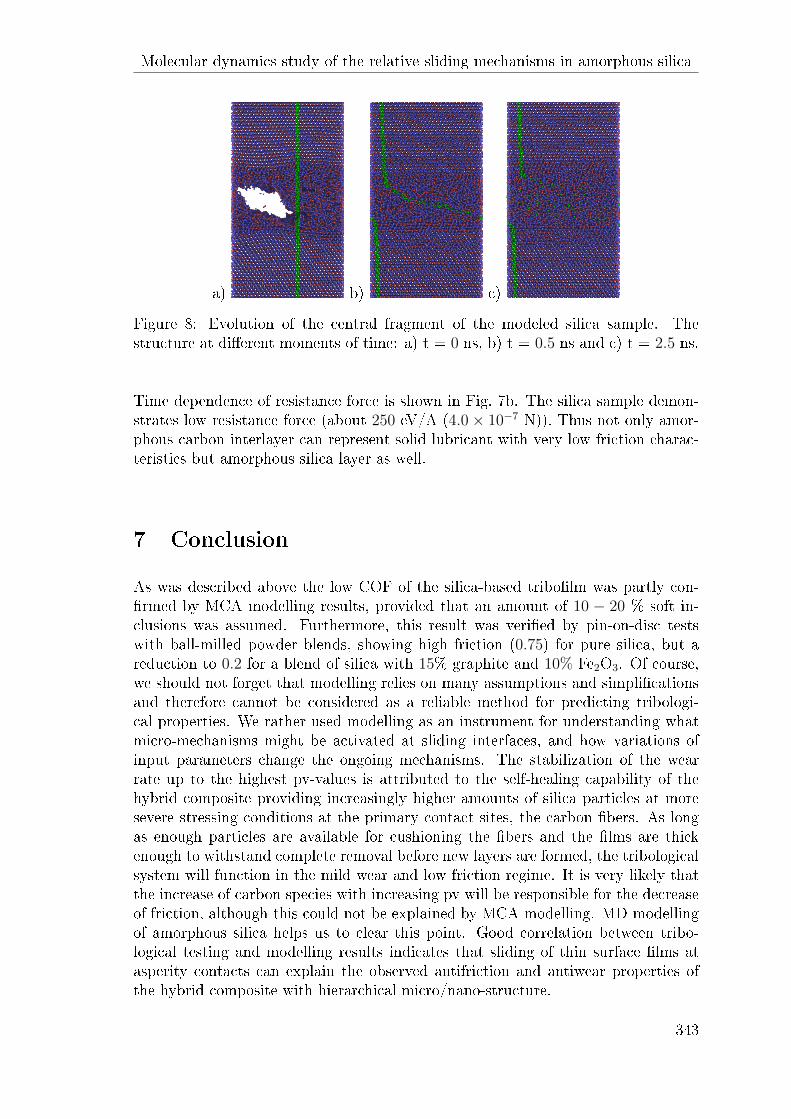
Figure 8: Evolution of the central fragment of the modeled silica sample. Thestructure at di�erent moments of time: a) t = 0 ns, b) t = 0.5 ns and c) t = 2.5 ns.
Time dependence of resistance force is shown in Fig. 7b. The silica sample demon-strates low resistance force (about 250 eV/A (4.0× 10⁻⁷ N)). Thus not only amor-phous carbon interlayer can represent solid lubricant with very low friction charac-teristics but amorphous silica layer as well.
7 Conclusion
As was described above the low COF of the silica-based tribo�lm was partly con-�rmed by MCA modelling results, provided that an amount of 10 − 20 % soft in-clusions was assumed. Furthermore, this result was veri�ed by pin-on-disc testswith ball-milled powder blends, showing high friction (0.75) for pure silica, but areduction to 0.2 for a blend of silica with 15% graphite and 10% Fe2O3. Of course,we should not forget that modelling relies on many assumptions and simpli�cationsand therefore cannot be considered as a reliable method for predicting tribologi-cal properties. We rather used modelling as an instrument for understanding whatmicro-mechanisms might be activated at sliding interfaces, and how variations ofinput parameters change the ongoing mechanisms. The stabilization of the wearrate up to the highest pv-values is attributed to the self-healing capability of thehybrid composite providing increasingly higher amounts of silica particles at moresevere stressing conditions at the primary contact sites, the carbon �bers. As longas enough particles are available for cushioning the �bers and the �lms are thickenough to withstand complete removal before new layers are formed, the tribologicalsystem will function in the mild wear and low friction regime. It is very likely thatthe increase of carbon species with increasing pv will be responsible for the decreaseof friction, although this could not be explained by MCA-modelling. MD-modellingof amorphous silica helps us to clear this point. Good correlation between tribo-logical testing and modelling results indicates that sliding of thin surface �lms atasperity contacts can explain the observed antifriction and antiwear properties ofthe hybrid composite with hierarchical micro/nano-structure.
343

REFERENCES
Acknowledgements
The results of MCA modelling were supported by RFBR grant no. 14-08-91330. MDresults were obtained under RSF grant no. 14-19-00718.
References
[1] S. Zhou, Q. Zhang, C. Wu, J. Huang. Materials and Design 44 (2013) 493-499
[2] I. Ab Rahman, V. Padavettan. J Nanomater 2012. Doi:10.1155/2012/132424
[3] K. Friedrich, Z. Zhang, A.K. Schlarb. Composites Science and Technology 65(2005) 1411-1421
[4] G. Zhang, R. Sebastian, T. Burkhart, K. Friedrich. Wear 292-293 (2012) 176-187
[5] G. Zhang, I. H�ausler, W. �Osterle, B. Wetzel, B. Jim. Wear 342-343 (2015)181-188
[6] M. Godet. Wear 1-3 (1984) 437-452
[7] S. Jacobson, S. Hogmark. Tribo�lms - on the crucial importance of tribologicallyinduced surface modi�cations. In G.K. Niclas (ed.). Recent Developments inWear Prevention, Friction and Lubrication. Kerala, India: Research Signpost;2010, 197-225. ISBN:978-87-308-03777-7
[8] W. �Osterle, A. Dmitriev. SAE Int. J. Passeng. Cars - Mech. Syst. 7(4) (2014),doi:10.4271/2014-01-2490
[9] A.I. Dmitriev, W. �Osterle, B. Wetzel, G. Zhang. Computational Materials Sci-ence 110 (2015) 204-214
[10] W. �Osterle, A.I. Dmitriev, H. Kloß. Tribol. Lett. 54 (2014) 257-262
[11] P. Thomas, J.L. Mansot, A. Molza, F. Begarin, M. Dubois, K. Guerin. Tri-bol.Lett. 56 (2014) 259-271
[12] J. Terso�. Phys.Rev. B37 (1988) 6991
Nikonov A.Yu., Akademichesky 2/4, 634055, Tomsk, Russia
Dmitriev A.I., Akademichesky 2/4, 634055, Tomsk, Russia�Osterle W., Unter der Eichen 87, Berlin, D-12200, Germany
344