Molecular dynamics simulations of nanodroplet spreading on solid...
23
IOP PUBLISHING FLUID DYNAMICS RESEARCH Fluid Dyn. Res. 42 (2010) 035501 (23pp) doi:10.1088/0169-5983/42/3/035501 Molecular dynamics simulations of nanodroplet spreading on solid surfaces, effect of droplet size Nahid Sedighi 1 , Sohail Murad 2 and Suresh K Aggarwal 1,3 1 Department of Mechanical and Industrial Engineering, University of Illinois at Chicago, Chicago, IL, USA 2 Department of Chemical Engineering, University of Illinois at Chicago, Chicago, IL, USA E-mail: [email protected] Received 20 July 2009, in final form 3 November 2009 Published 28 January 2010 Online at stacks.iop.org/FDR/42/035501 Communicated by H J Sung Abstract Molecular dynamics simulations were performed to study the spreading characteristics of nano-sized droplets on solid surfaces. The spreading behavior was analyzed in terms of the temporal evolution of the dynamic contact angle and spreading diameter for wettable, partially wettable and non- wettable surfaces. The computational model was validated through qualitative comparison with the measurements of Bayer and Megaridis, and through comparison with existing correlations. The comparison based on the ratio of relevant time scales indicated that for the conditions investigated, the spreading dynamics is governed by inertial and surface forces, with negligible influence of viscous forces. In addition, the simulation results indicated that the dynamic contact angle and spreading diameter, as well as the advancing and receding time periods, exhibit strong dependence on droplet size. These results were further analyzed to obtain correlations for the effect of droplet size on these spreading parameters. The correlations indicated that the normalized spreading diameter and contact angle scale with drop diameter as D m / D 0 ∝ D 0.5 0 and θ R ∝ D 0.5 0 , while the advancing and receding time periods scale as t ∝ D 2/3 0 . Global kinetic energy and surface energy considerations were used to provide a physical basis for these correlations. The correlations were also found to be generally consistent with the experimentally observed spreading behavior of macroscopic droplets. (Some figures in this article are in colour only in the electronic version) 3 Author to whom any correspondence should be addressed. © 2010 The Japan Society of Fluid Mechanics and IOP Publishing Ltd Printed in the UK 0169-5983/10/035501+23$30.00 1
Transcript of Molecular dynamics simulations of nanodroplet spreading on solid...
IOP PUBLISHING FLUID DYNAMICS RESEARCH
Fluid Dyn. Res. 42 (2010) 035501 (23pp) doi:10.1088/0169-5983/42/3/035501
Molecular dynamics simulations of nanodropletspreading on solid surfaces, effect of droplet size
Nahid Sedighi1, Sohail Murad2 and Suresh K Aggarwal1,3
1 Department of Mechanical and Industrial Engineering, University of Illinois at Chicago,Chicago, IL, USA2 Department of Chemical Engineering, University of Illinois at Chicago, Chicago, IL, USA
E-mail: [email protected]
Received 20 July 2009, in final form 3 November 2009Published 28 January 2010Online at stacks.iop.org/FDR/42/035501
Communicated by H J Sung
AbstractMolecular dynamics simulations were performed to study the spreadingcharacteristics of nano-sized droplets on solid surfaces. The spreadingbehavior was analyzed in terms of the temporal evolution of the dynamiccontact angle and spreading diameter for wettable, partially wettable and non-wettable surfaces. The computational model was validated through qualitativecomparison with the measurements of Bayer and Megaridis, and throughcomparison with existing correlations. The comparison based on the ratio ofrelevant time scales indicated that for the conditions investigated, the spreadingdynamics is governed by inertial and surface forces, with negligible influenceof viscous forces. In addition, the simulation results indicated that the dynamiccontact angle and spreading diameter, as well as the advancing and recedingtime periods, exhibit strong dependence on droplet size. These results werefurther analyzed to obtain correlations for the effect of droplet size on thesespreading parameters. The correlations indicated that the normalized spreadingdiameter and contact angle scale with drop diameter as Dm/D0 ∝ D0.5
0 andθR ∝ D0.5
0 , while the advancing and receding time periods scale as t ∝ D2/30 .
Global kinetic energy and surface energy considerations were used to providea physical basis for these correlations. The correlations were also found to begenerally consistent with the experimentally observed spreading behavior ofmacroscopic droplets.
(Some figures in this article are in colour only in the electronic version)
3 Author to whom any correspondence should be addressed.
© 2010 The Japan Society of Fluid Mechanics and IOP Publishing Ltd Printed in the UK0169-5983/10/035501+23$30.00 1
Fluid Dyn. Res. 42 (2010) 035501 N Sedighi et al
1. Introduction
Spreading of droplets on solid surfaces is important in a wide variety of applications,including propulsion, industrial surface coating, spray painting, spray cooling, ink-jet printing,agricultural sprays and biological sensors. In coating applications, a spatially uniform coatingrequires fundamental understanding of the mechanisms that influence the spreading dynamics.Similarly in agricultural sprays, the objective is to cover a foliar surface with the desiredmaterial as fast and uniformly as possible. In many propulsion applications, the wallimpingement of liquid droplets often determines the fuel vapor distribution and thereby thecombustion and emission characteristics. In spray cooling, the droplet spreading has a stronginfluence on the heat transfer characteristics.
Inkjet printing involves droplet deposition on a moving or stationary surface (Pedeet al 1998, Choi et al 2004, Boland et al 2007) and is used in numerous applications,including desktop printing, electronic circuitry for generating conductive tracks and electroniccomponents, and printing transparent coatings and thin films for transistors, solar cells anddisplays (Lee et al 2007). It is also used for printing proteins, DNA and cells in medicaldevices. Inkjet printing is a key technology in microelectronics and fabrication of micro andnano devices. In microelectronics, metallic conducting tracks are produced by depositing aseries of droplets, containing an organo-metallic compound (or metal nanoparticles) dissolvedin a carrier fluid, on a moving substrate (Lee and Kim 2000). As the droplet spreads on thesurface, the carrier fluid evaporates and the organo-metallic compound (or nanoparticles)is deposited, forming a metallic track. The quality, lateral resolution and morphologicalproperties of the track formed strongly depend on the droplet spreading dynamics (Graham-Rowe 2007), while the track width depends on the equilibrium contact angle. Importantparameters affecting the wetting behavior include the liquid viscosity and surface tension,droplet size and velocity, droplet and surface temperatures, substrate speed and surfacewettability.
Characterizing the dynamic spreading behavior has been very challenging, as it involvesscales ranging from continuum to molecular, and the relevant parameters, such as Webernumber (We) and capillary number (Ca), can vary over a wide range (Hoffman 1975,Blake 2006). Moreover, it has a wide variety of applications, involving different fluids andsubstrates, which further adds to the complexity. A common quantity used to characterizedynamic spreading is the contact angle of the moving wetting line, or the dynamic contactangle θ(t) (Yarin 2006). From a macroscopic view, the forced spreading is governed bythe inertial and surface forces, and the dynamic contact angle decreases rapidly, while thespreading diameter increases during the early stages of spreading. The dynamic contact angleduring this stage (advancing stage) is significantly different from the equilibrium value. Thisis followed by the second stage characterized by a slow change in the contact angle, as itapproaches its equilibrium value. On the other hand, for instantaneous droplet spreading, thedynamic wetting process is governed by the capillary and viscous forces, as the contact angledecreases from its initial value of 180◦ to its equilibrium value θE.
Experimental studies concerning droplet spreading have focused on characterizing thespreading behavior as a function of important parameters (We, Ca, etc), and determiningthe dynamic and equilibrium contact angles as well as the maximum spreading ratio(Dm/D0), which is defined as the ratio of the maximum droplet diameter during spreadingto the original diameter. These studies generally employed mm-size droplets and variousimaging techniques to capture droplet deformation following its impact on a given substrate.Accordingly, a number of correlations has been developed to quantify the effects of We, Caand other parameters on the spreading characteristics (Pasandideh-Fard et al 1996, Aziz and
2
Fluid Dyn. Res. 42 (2010) 035501 N Sedighi et al
Chandra 2000, Crooks et al 2001, Sikalo et al 2002, Bathel et al 2007). Several of thesecorrelations are listed in Bathel et al (2007).
Theoretical studies have generally followed two approaches to describe the dynamicspreading phenomenon and provide correlations for the temporal variation of the spreadingdiameter and contact angle as well as the relationship between dynamic contact angle andslip line velocity. The first approach is based on the hydrodynamic theory (Tanner 1979,Cox 1986, Shikhmurzaev 1997, Blake 2006) that considers droplet spreading from acontinuum viewpoint. It employs an appropriate model to account for molecular processesin the microscopic layer in the vicinity of the moving contact line, and to provide arelationship between the macroscopic and microscopic contact angles. In order to avoid theshear stress singularity at the contact line, the no-slip boundary condition is appropriatelymodified by using different slip conditions (Bayer and Megaridis 2006). Theoretical andcomputational studies here have employed simplified analysis based on the force andenergy balance (Yang 1975, Chandra and Avedisian 1991, Asai et al 1993, Scheller andBousfield 1995, Mao et al 1997) as well as on the solution of the appropriate Navier-Stokesequations (Zhao et al 1996, Delplanque and Rangel 1997) to obtain correlations for the effectsof important parameters (We, Ca, etc) on spreading characteristics. The second approachemploys a molecular-kinetic theory (Blake and Haynes 1969, Cherry and Holmes 1969),which postulates that the macroscopic wetting behavior is determined by the overall statisticsof the individual molecular displacements occurring within the three-phase zone. Thus, thecontact line motion occurs due to the jumping of molecules from the liquid to the vaporside of the contact line, and its velocity is determined by the frequency κ and length λ
of the individual molecular displacements. Shikhmurzaev (1997) presents a unifying modelcombining the two approaches. Blake (2006) provides an elegant discussion of these modelsand the related experimental studies concerning the validation of the models.
Clearly, the phenomenon of droplet spreading on solid substrates has been extensivelyinvestigated, and good phenomenological understanding and numerous correlations havebeen developed. However, mechanisms associated with the contact line motion and dynamicspreading are still not well understood (Dussan 1979, de Gennes 1985, Cazabat et al 1990).Moreover, a unifying approach to describe the dynamics of spreading in different systemsis not yet available (De Coninck et al 2001). This may partly be attributed to the widerange of scales associated with the dynamic spreading processes, and experimental difficultiesin capturing the spreading dynamics especially for droplet sizes in the sub-mm range. Forexample, for a drop-on-demand inkjet system, the advancing stage lasts less than 100 µs formicron-size droplets (Dong et al 2006). While high-speed imaging techniques have providedmuch useful information (Attinger et al 2000, Kim et al 2003, Van Dam and Le Clerc 2004),they have not yielded time-resolved measurements for such droplet sizes. Moreover, ourliterature review indicates that while the dynamic wetting behavior at the continuum scale hasbeen extensively investigated, relatively few studies have been reported dealing with nano-sized droplets.
In the present study, we have performed molecular dynamics (MD) simulations toinvestigate the dynamic spreading behavior of nano-size droplets impinging on flat surfaceswith different wetting characteristics. The major objective is to examine the effect of dropletsize on spreading dynamics, characterized in terms of the temporal variations of contactangle and spreading diameter, as well as the advancing and receding time periods. Previousinvestigations using MD simulations (Heslot et al 1989, Cazabat et al 1990, Yang et al 1991,De Coninck et al 1995, Voue et al 1998a, 1998b; de Ruijter et al 1999, Heine et al 2003) havenot examined these aspects. For example, the study by Voue et al focuses on the film diffusionrate as a function of the solid–fluid interaction potentials. Their results show agreement with
3
Fluid Dyn. Res. 42 (2010) 035501 N Sedighi et al
Table 1. System properties used in MD simulations.
D0 NParticles
(nm) εw εf Box dim. [σ ] Total Drop Surface Ambient
6 1, 0.15, 0.05 1.0 34.9 × 34.9 × 69.8 5553 2123 2440 9909 1, 0.15, 0.05 1.0 52.4 × 52.4 × 104.8 21232 7011 10920 3301
12 1, 0.15, 0.05 1.0 69.8 × 69.8 × 139.7 44048 16757 19360 7931
experiments, which found non-monotonic dependence of the diffusion rate on the strengthof the fluid–solid interaction. The simulations reported a maximum value for intermediatestrengths of solid–fluid interactions. For high strength interactions, the fluid structure mimicsthe solid structure, and that limits the diffusion rates. In our previous study (Sedighiet al 2009), an efficient algorithm was developed to track the liquid-phase interface and thedynamic contact angle for a liquid droplet in contact with two solid surfaces. This algorithmis used to investigate the droplet spreading dynamics in the present study. The numericalmodel is validated by qualitatively and semi-quantitatively comparing our simulations withthe measurements of Bayer and Megaridis (2006). Simulations are then used to examine thedynamic spreading behavior, and the effects of surface wettability and droplet size on thespreading characteristics. In the next two sections, we describe the simulation model and itsvalidation. This is followed by the discussion of results on the effects of droplet size on spread-ing dynamics, and the scaling relationships. Conclusions are presented in the last section.
2. Computational model
We examined the spreading behavior of nano-sized liquid argon droplets on solid surfacesusing MD simulations. The simulation system is a 3D box that consists of 44 048 argonatoms4, which constitute the liquid droplet, solid surface and ambient gas atoms. Theinteractions between molecules were represented by the Lennard-Jones (LJ) potential
φ(r) = 4ε[(σ/r)12− (σ/r)6], (1)
where σ and ε are the characteristic length and energy parameters of the LJ potential. Thepotential was truncated at a cut-off distance of 3σ , as is usual in such models (Allen andTildesley 1987). For argon atoms, ε = 1.67 × 10⁻²¹ J and σ = 3.405 Å. The dimensions ofthe simulation box and the values of various parameters used in simulations are provided intable 1. The liquid density and temperature are 0.75 σ−3 and 0.72 ε/k, respectively. The fluidparticles can move freely in the 3D system and periodic boundary conditions are employedat the system boundaries. For the result shown, we used ρf = 0.75σ−3 for the droplet. Thesurrounding (ambient) gas had an initial density of ρa = 0.0167ρf, and the reduced initialtemperature was T ∗
= kT /ε = 0.72. Note that the subscripts f, a and w denote, respectively,the droplet fluid, ambient fluid and wall (surface).
The surface–surface interactions were also modeled with the LJ potential. Each wallatom was attached to the lattice site with a simple harmonic potential, with a spring constantof K = 100ε/σ 2, and is allowed to oscillate due to thermal fluctuations around its latticeposition. The equations of motion were integrated using Gear’s fifth order predictor–correctoralgorithm. The time step is 1t = 0.005τ = 1.078 × 10⁻² ps, where τ = (mσ 2/ε)1/2 with mthe mass of an argon atom. Note that all variables reported here are normalized with respectto argon parameters (ε = 1.67 × 10⁻²¹ J, σ = 3.405 Å and m = 39.948 amu). The system was
4 This value corresponds to the 12 nm droplet case.
4
Fluid Dyn. Res. 42 (2010) 035501 N Sedighi et al
initialized for approximately 500 time steps. The coordinates of all molecules were sampledevery 500 steps for subsequent analysis. The droplet initially has a spherical shape, andis placed at the geometric center of the surface with an initial velocity of 1.25 m s−1. Theimpact velocity was chosen to allow us to observe key steps of the spreading phenomena. Thedroplet is allowed impinge on the surface and then spread. The spreading is influenced by boththe magnitude of initial impact velocity and the interaction between the liquid/surface/vapormolecules.
Several sets of MD simulations were performed to examine the effect of droplet size onthe dynamic spreading behavior. Three droplets with diameters of 6, 9 and 12 nm have beenconsidered. The wetting and spreading of each droplet is examined on surfaces with high tolow surface energies. This variation resulted in three different surfaces, wettable (θe < 40),partially wettable 40 < θe < 140 and non-wettable (θe > 140). Here θe represents the equi-librium or static contact angle. The system parameters used in our simulations are listed intable 1. Here εw is the reduced interaction energy of the surface with respect to liquid, i.e.ε∗
w = εw/εf where for simplicity from hereon the asterisk is removed and it is written as εw.After the initial impact of the droplet with the surface, we observed rapid radial spreading,
resulting in the flattening and recoiling of the drop. To investigate the dynamics of dropletspreading and contact angle evolution, an algorithm was developed to track the interface andcompute the contact angle using density profiles. The liquid–vapor interface was defined whenthe density is approximately 25% of the bulk liquid value. This interface was then used tocompute contact angle (slope of the curve passing through the interfacial points). As discussedby Sedighi et al (2009), the uncertainty in the calculation of contact angle is generally lessthan 10%. The spreading diameter and time evolution of spreading were monitored at differentstages of the spreading process.
3. Results and discussion
3.1. Model validation and dynamics of spreading
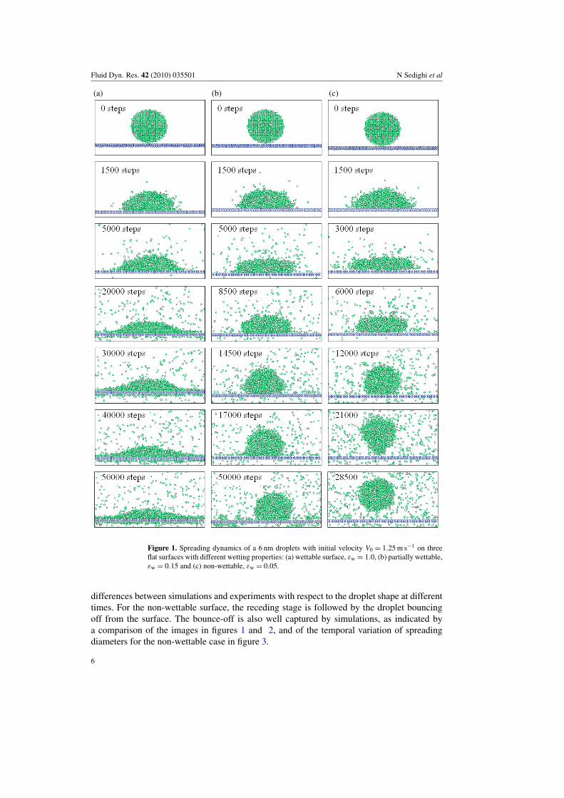
In order to validate the computational model, we compared our simulation results withmeasurements of Bayer and Megaridis (2006) for the impact of a 1.4 mm water droplet onflat surfaces with different wetting characteristics. Note that the comparison is qualitativedue to different conditions in simulations and measurements. Consequently, the comparisonof spreading characteristics presented in figures 1 and 2 provides reasonable justificationrather than validation for the computational model. The impact velocity in their study was0.77 m s−1. Figure 1 shows images from our simulation at various times for the dynamicspreading of a 6 nm droplet on wettable (ε = 1), partially wettable (ε = 0.15) and non-wettable (ε = 0.05) surfaces. Figure 2 presents the corresponding images from the cited study.While there are significant quantitative differences between simulations and measurementsdue to the vastly different conditions, there is also striking similarity between them. Thesimulations are able to reproduce the overall spreading behavior observed experimentallyfor all three surfaces. Based on the images presented in figures 1 and 2, and the temporalevolution of spreading diameter in figure 3, the overall spreading process can be dividedinto two stages: an advancing stage during which the droplet base expands and the spreadingdiameter increases rapidly to nearly its maximum value, followed by a receding stage5 duringwhich the droplet base shrinks, i.e. the contact diameter decreases (Starov et al 2002). Thespreading behavior during these two stages is well captured by simulations, although there are
5 The receding stage is not observed for the wettable case (cf figures 1–3). This is also consistent with theobservations of Starov et al (2002).
5
Fluid Dyn. Res. 42 (2010) 035501 N Sedighi et al
(a) (b) (c)
Figure 1. Spreading dynamics of a 6 nm droplets with initial velocity V0 = 1.25 m s−1 on threeflat surfaces with different wetting properties: (a) wettable surface, εw = 1.0, (b) partially wettable,εw = 0.15 and (c) non-wettable, εw = 0.05.
differences between simulations and experiments with respect to the droplet shape at differenttimes. For the non-wettable surface, the receding stage is followed by the droplet bouncingoff from the surface. The bounce-off is also well captured by simulations, as indicated bya comparison of the images in figures 1 and 2, and of the temporal variation of spreadingdiameters for the non-wettable case in figure 3.
6

Fluid Dyn. Res. 42 (2010) 035501 N Sedighi et al
Figure 2. Spreading dynamics of 1.4 mm water droplets with V0 = 0.7 m s−1 on three flat surfaceswith different degrees of wetting: (a) wettable, (b) partially wettable and (c) non-wettable. Takenfrom Bayer and Megaridis (2006).
There are other notable similarities between simulations and experiments. Firstly, both thesimulations and experiments indicate that for an inertial impact, the spreading process duringthe advancing stage and the variation of Dm/D0 are relatively insensitive to the surface wettingproperties. This can be seen in the first three images from the simulations and experiments forall the three surfaces (cf figures 1 and 2), as well as from the temporal variation of Dm/D0
in figure 3. Secondly, for the wettable surface, the spreading process following the advancingstage is characterized by a slow relaxation to equilibrium whereby the spreading diameterremains nearly constant or increases at a very slow rate, as indicated in figures 1–3, while
7
Fluid Dyn. Res. 42 (2010) 035501 N Sedighi et al
(b)
+
++++++++++++++++++++
+++++++++++++++++++++++++++++D
m/D
0
0 10 000 20000Time
30000 40 000 500000
1
2
3
ε = 1 (wetting)
ε = 0.15 ( partial wetting)
ε = 0.05 (non-wetting)
+
(a)
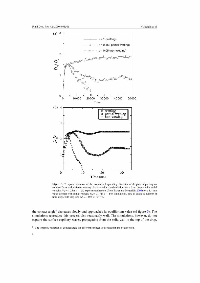
Figure 3. Temporal variation of the normalized spreading diameter of droplets impacting onsolid surfaces with different wetting characteristics: (a) simulations for a 6 nm droplet with initialvelocity, V0 = 1.25 m s−1, (b) experimental results (from Bayer and Megaridis 2006) for a 1.4 mmwater droplet with initial velocity V0 = 0.77 m s−1. For simulations, time is given in number oftime steps, with step size 1t = 1.078 × 10⁻¹⁴ s.
the contact angle6 decreases slowly and approaches its equilibrium value (cf figure 5). Thesimulations reproduce this process also reasonably well. The simulations, however, do notcapture the surface capillary waves, propagating from the solid wall to the top of the drop,
6 The temporal variation of contact angle for different surfaces is discussed in the next section.
8
Fluid Dyn. Res. 42 (2010) 035501 N Sedighi et al
observed in the experimental study. This may be due to the extremely small length and timescales used in simulations, and needs to be investigated in a future study.
Results in figures 1–3 further indicate that the spreading process during the receding stageis strongly influenced by surface wettability. Both the simulations and experiments indicatethat for partially wettable and non-wettable surfaces, the receding stage is characterized bythe decrease in spreading diameter or retraction of the contact line. This is clearly indicatedby the experimental images at 10.6, 15.4 and 21.4 ms for the partially wettable surface,and at 6.6, 10.2 and 11.4 ms for the non-wettable surface in figure 2. The simulations alsoproduce this overall behavior, as indicated by images at 8500, 14 500 and 17 000 steps forthe partially wettable surface, and at 6000, 12 000 and 21 000 steps for the non-wettablesurface in figure 1. There are, however, differences between simulations and experimentswith respect to the droplet shape and the oscillations observed in experiments. As shown infigures 1–3, the experimentally observed variation in droplet shape and spreading diameterduring the receding period is not well captured by simulations. Moreover, simulations are notable to reproduce the surface capillary waves observed in experiments. This may be due to theextremely small length and time scales used in simulations, as noted earlier. The spreadingnear the end of the receding stage is characterized by the contact diameter approaching itsequilibrium value for the partially wettable surface, while it involves droplet bounce-off for thenon-wettable surface. The liquid separation from the surface and the droplet bouncing fromthe non-wettable surface can be seen in the experimental image at 15.8 ms (figure 2), and at28 500 steps in simulations (figure 1). These receding and bouncing processes observed in oursimulations are also consistent with the results reported by Ok et al (2004) for continuum-sizedroplets.
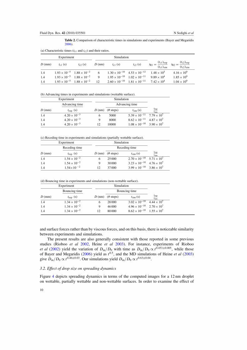
The similarity between our simulations and reported experiments is further examinedusing the relevant characteristic times associated with the advancing, receding and bouncingprocesses. The advancing, receding and bounce-off times obtained from the experimentsand simulations are listed in tables 2(b)–(d), respectively. Note that the experimental valuesare only approximate, as these were estimated from figures 2 and 3. Since the time andlengths scales are vastly different between simulations and reported experiments, the relevantcharacteristic times may be computed based on the consideration that the spreading process isgoverned by inertial, viscous and surface forces. This yields the following two characteristictime scales:
tc1 = µDo/γ, tc2 = ρD2o V/γ
The first time scale (tc1) considers viscous and surface forces, while the second (tc2) considersinertial and surface forces. Here V and Do are the droplet impact velocity and diameter,respectively, and µ, ρ and γ are the liquid viscosity, density and surface tension, respectively.The values of tc1 and tc2 for the water (experiments) and argon7 (simulations) droplets arelisted in table 2(a). Due to the vastly different scales used in experiments and simulations, itis relevant to compare the ratio of various time scales. The ratios of tc1 and tc2, termed as tR1
and tR2, are shown in table 2(a), while those of the advancing, receding and bouncing times inexperiments and simulations are shown in tables 2(b)–(d), respectively. As indicated in thesetables, the ratios of the advancing, receding and bouncing times for the three surfaces andthree droplet sizes vary within a factor of three. More importantly, these ratios differ from tR2
(ratio of the experimental and computational characteristic times based on inertial and surfaceforces) by about an order of magnitude, while they differ from tR1 (ratio of the experimentaland computational characteristic times based on viscous and surface forces) by three orders ofmagnitude. Thus the comparison indicates that the spreading process is governed by inertial
7 The argon properties were calculated using the NIST database.
9
Fluid Dyn. Res. 42 (2010) 035501 N Sedighi et al
Table 2. Comparison of characteristic times in simulations and experiments (Bayer and Megaridis2006).
(a) Characteristic times (tc1 and tc2) and their ratios.
Experiment Simulation
D (mm) tc1 (s) tc2 (s) D (nm) tc1 (s) tc2 (s) tR1 =(tc1)exp
(tc1)simtR2 =
(tc2)exp
(tc2)sim
1.4 1.93 × 10⁻⁵ 1.88 × 10⁻² 6 1.30 × 10⁻¹⁰ 4.53 × 10⁻¹² 1.48 × 10⁵ 4.16 × 10⁹
1.4 1.93 × 10⁻⁵ 1.88 × 10⁻² 9 1.95 × 10⁻¹⁰ 1.02 × 10⁻¹¹ 9.89 × 10⁴ 1.85 × 10⁹
1.4 1.93 × 10⁻⁵ 1.88 × 10⁻² 12 2.60 × 10⁻¹⁰ 1.81 × 10⁻¹¹ 7.42 × 10⁴ 1.04 × 10⁹
(b) Advancing times in experiments and simulations (wettable surface).
Experiment Simulation
Advancing time Advancing time
D (mm) texp (s) D (nm) (# steps) tsim (s)texptsim
1.4 4.20 × 10⁻³ 6 5000 5.39 × 10⁻¹¹ 7.79 × 10⁷
1.4 4.20 × 10⁻³ 9 8000 8.62 × 10⁻¹¹ 4.87 × 10⁷
1.4 4.20 × 10⁻³ 12 10000 1.08 × 10⁻¹⁰ 3.90 × 10⁷
(c) Receding time in experiments and simulations (partially wettable surface).
Experiment Simulation
Receding time Receding time
D (mm) texp (s) D (nm) (# steps) tsim (s)texptsim
1.4 1.54 × 10⁻² 6 25 000 2.70 × 10⁻¹⁰ 5.71 × 10⁷
1.4 1.54 × 10⁻² 9 30 000 3.23 × 10⁻¹⁰ 4.76 × 10⁷
1.4 1.54×10 −2 12 37 000 3.99 × 10⁻¹⁰ 3.86 × 10⁷
(d) Bouncing time in experiments and simulations (non-wettable surface).
Experiment Simulation
Bouncing time Bouncing time
D (mm) texp (s) D (nm) (# steps) tsim (s)texptsim
1.4 1.34 × 10⁻² 6 28 000 3.02 × 10⁻¹⁰ 4.44 × 10⁷
1.4 1.34 × 10⁻² 9 46 000 4.96 × 10⁻¹⁰ 2.70 × 10⁷
1.4 1.34 × 10⁻² 12 80 000 8.62 × 10⁻¹⁰ 1.55 × 10⁷
and surface forces rather than by viscous forces, and on this basis, there is noticeable similaritybetween experiments and simulations.
The present results are also generally consistent with those reported in some previousstudies (Rioboo et al 2002, Heine et al 2003). For instance, experiments of Riobooet al (2002) yield the variation of Dm/D0 with time as Dm/D0 ∝ t0.453±0.005, while thoseof Bayer and Megaridis (2006) yield as t0.5, and the MD simulations of Heine et al (2003)give Dm/D0 ∝ t0.46±0.03. Our simulations yield Dm/D0 ∝ t0.63±0.04.
3.2. Effect of drop size on spreading dynamics
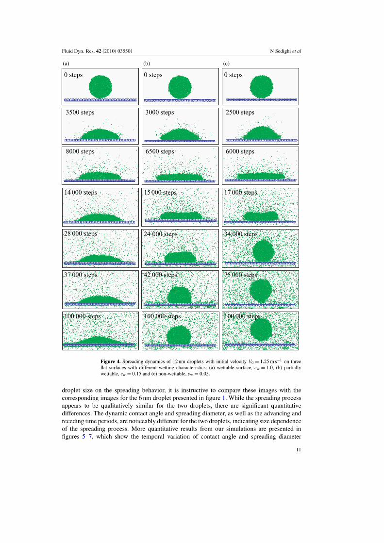
Figure 4 depicts spreading dynamics in terms of the computed images for a 12 nm dropleton wettable, partially wettable and non-wettable surfaces. In order to examine the effect of
10
Fluid Dyn. Res. 42 (2010) 035501 N Sedighi et al
0 steps
3500 steps
8000 steps
14 000 steps
28 000 steps
37 000 steps
100 000 steps
0 steps
3000 steps
6500 steps
15000 steps
24 000 steps
42 000 steps
100 000 steps
0 steps
2500 steps
6000 steps
17 000 steps
34 000 steps
75 000 steps
100 000 steps
(a) (b) (c)
Figure 4. Spreading dynamics of 12 nm droplets with initial velocity V0 = 1.25 m s−1 on threeflat surfaces with different wetting characteristics: (a) wettable surface, εw = 1.0, (b) partiallywettable, εw = 0.15 and (c) non-wettable, εw = 0.05.
droplet size on the spreading behavior, it is instructive to compare these images with thecorresponding images for the 6 nm droplet presented in figure 1. While the spreading processappears to be qualitatively similar for the two droplets, there are significant quantitativedifferences. The dynamic contact angle and spreading diameter, as well as the advancing andreceding time periods, are noticeably different for the two droplets, indicating size dependenceof the spreading process. More quantitative results from our simulations are presented infigures 5–7, which show the temporal variation of contact angle and spreading diameter
11
Fluid Dyn. Res. 42 (2010) 035501 N Sedighi et al
+
+
+
++
+++
+++
+
++
+++
+++
++++++++++++ + + +
+ + + + + + + ++
Con
tact
angl
e(θ
)
0 10 000 20 000 30 000 40 000 50 000–20
0
20
40
60
80
100
120
140
160
180
200
D = 12 nm
D = 9 nm
D = 6 nm
+
(a)
+
+
+
+
+++
+++++
++++++
+++
++++++++
++ + + + + + + + + + ++ + +
+ + + ++
Dm/D
0
0 10 000 20 000Time
30 000 40 000 50 0000
0.5
1.0
1.5
2.0
2.5
3.0
D = 12 nm
D = 9 nm
D = 6 nm
+
(b)
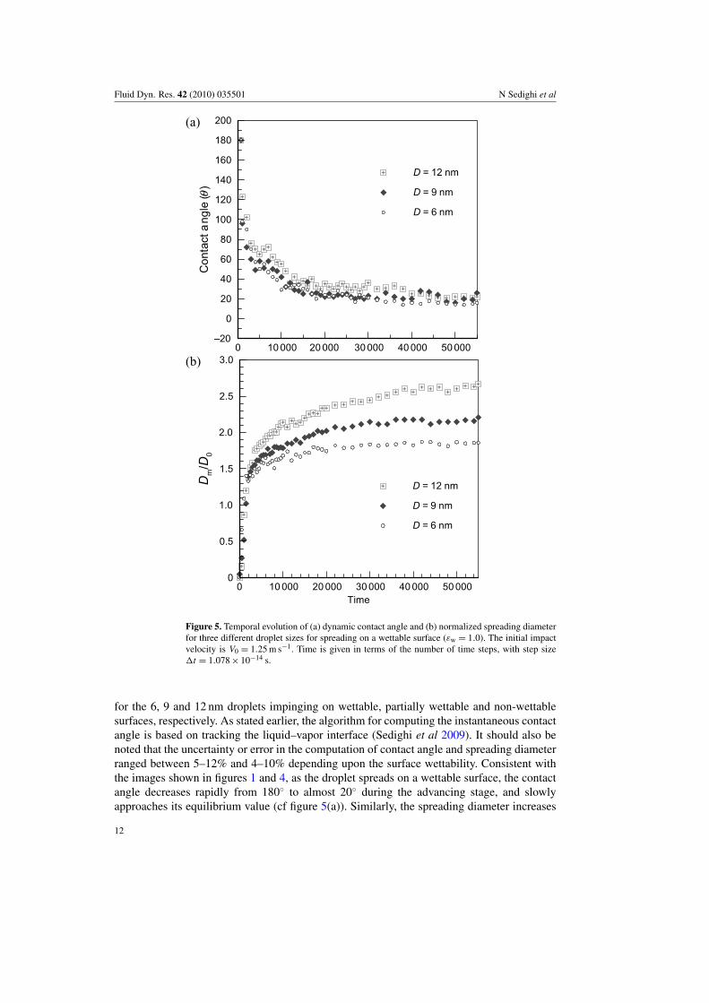
Figure 5. Temporal evolution of (a) dynamic contact angle and (b) normalized spreading diameterfor three different droplet sizes for spreading on a wettable surface (εw = 1.0). The initial impactvelocity is V0 = 1.25 m s−1. Time is given in terms of the number of time steps, with step size1t = 1.078 × 10⁻¹⁴ s.
for the 6, 9 and 12 nm droplets impinging on wettable, partially wettable and non-wettablesurfaces, respectively. As stated earlier, the algorithm for computing the instantaneous contactangle is based on tracking the liquid–vapor interface (Sedighi et al 2009). It should also benoted that the uncertainty or error in the computation of contact angle and spreading diameterranged between 5–12% and 4–10% depending upon the surface wettability. Consistent withthe images shown in figures 1 and 4, as the droplet spreads on a wettable surface, the contactangle decreases rapidly from 180◦ to almost 20◦ during the advancing stage, and slowlyapproaches its equilibrium value (cf figure 5(a)). Similarly, the spreading diameter increases
12
Fluid Dyn. Res. 42 (2010) 035501 N Sedighi et al
+
+
+
+
++++++++++++
+++++
+++++
+++
++
+
+ + +
+ + + + + + + ++C
onta
ctan
gle
(θ)
0 10 000 20 000 30 000 40 000 50 000–20
0
20
40
60
80
100
120
140
160
180
200
D = 12 nm
D = 9 nm
D = 6 nm
+
(a)
+
+
+
+++++
++
+++
+++
++
++
+ ++
++ + + + + + + + + + + + ++
Dm/D
0
0 10000 20 000 30 000 40 000 50 0000
0.5
1.0
1.5
2.0
2.5
3.0
D = 12 nm
D = 9 nm
D = 6 nm
+
(b)
Time
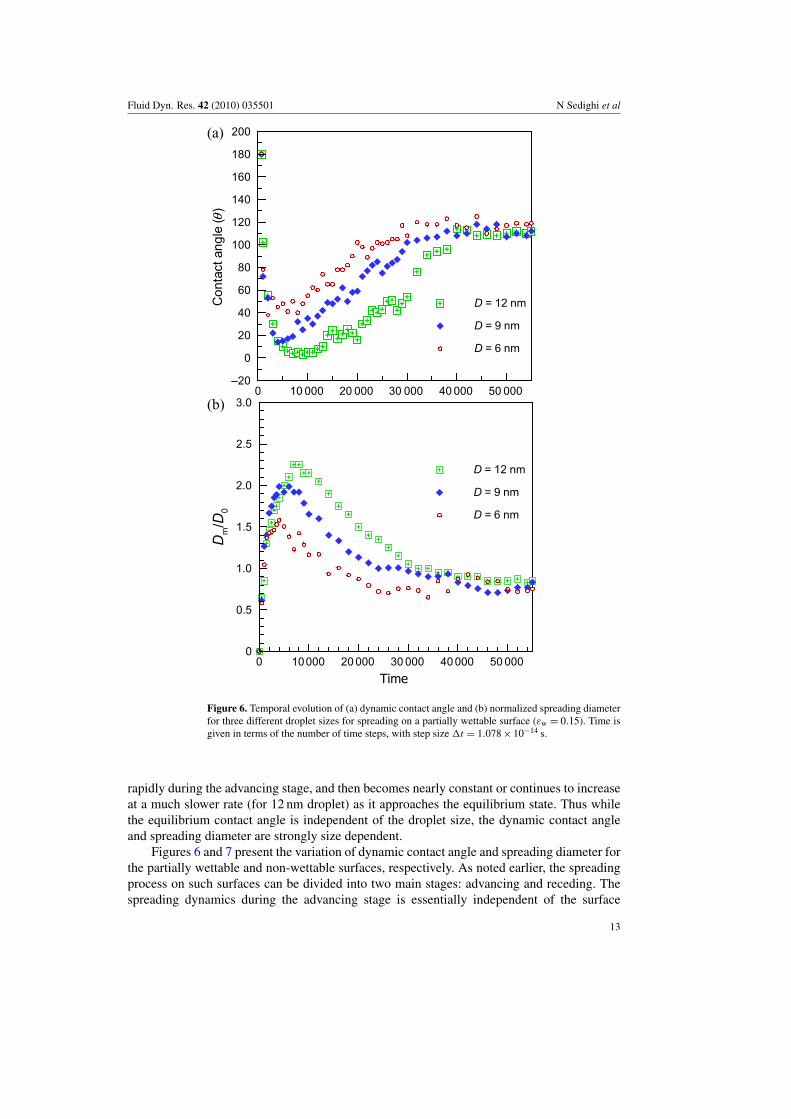
Figure 6. Temporal evolution of (a) dynamic contact angle and (b) normalized spreading diameterfor three different droplet sizes for spreading on a partially wettable surface (εw = 0.15). Time isgiven in terms of the number of time steps, with step size 1t = 1.078 × 10⁻¹⁴ s.
rapidly during the advancing stage, and then becomes nearly constant or continues to increaseat a much slower rate (for 12 nm droplet) as it approaches the equilibrium state. Thus whilethe equilibrium contact angle is independent of the droplet size, the dynamic contact angleand spreading diameter are strongly size dependent.
Figures 6 and 7 present the variation of dynamic contact angle and spreading diameter forthe partially wettable and non-wettable surfaces, respectively. As noted earlier, the spreadingprocess on such surfaces can be divided into two main stages: advancing and receding. Thespreading dynamics during the advancing stage is essentially independent of the surface
13
Fluid Dyn. Res. 42 (2010) 035501 N Sedighi et al
Con
tact
angl
e(θ
)
0 10 000 20 000 30 000 40 000 50 000–20
20
40
60
80
100
120
140
160
180
200
D = 12 nm
D = 9 nm
D = 6 nm
(a)
Dm/D
0
0 10 000 20 000 30 000 40000 500000
0.5
1.5
2.5
2.0
1.0
3.0
D = 12 nm
D = 9 nm
D = 6 nm
(b)
Time
+
+
+
++
+++++
++++
++
+++
+
++
++
++
++ + +
++ + +
+ +
+
+
+
+
+
++
+++++
+++
++
++
+++
++ +
+ ++ + + + + + + + +
+ + ++
+
Figure 7. Temporal evolution of (a) dynamic contact angle and (b) normalized spreading diameterfor three different droplet sizes spreading on a non-wettable surface (εw = 0.05). Time is given interms of the number of time steps, with step size 1t = 1.078 × 10⁻¹⁴ s.
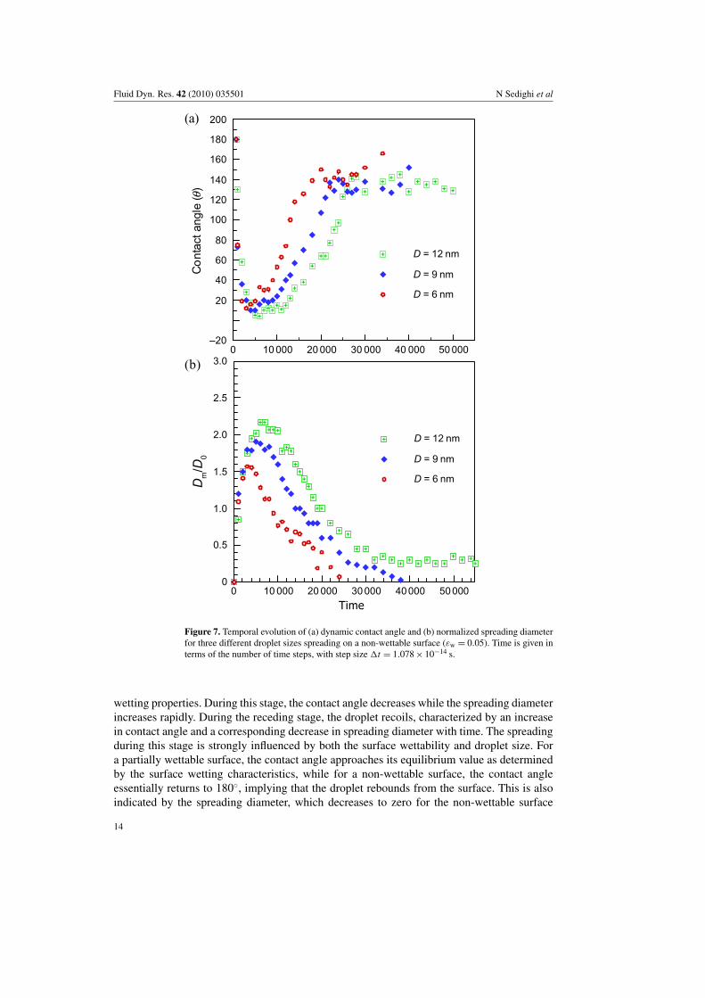
wetting properties. During this stage, the contact angle decreases while the spreading diameterincreases rapidly. During the receding stage, the droplet recoils, characterized by an increasein contact angle and a corresponding decrease in spreading diameter with time. The spreadingduring this stage is strongly influenced by both the surface wettability and droplet size. Fora partially wettable surface, the contact angle approaches its equilibrium value as determinedby the surface wetting characteristics, while for a non-wettable surface, the contact angleessentially returns to 180◦, implying that the droplet rebounds from the surface. This is alsoindicated by the spreading diameter, which decreases to zero for the non-wettable surface
14
Fluid Dyn. Res. 42 (2010) 035501 N Sedighi et al
Dm/D0
Con
tact
angl
e(θ
)
0 1 2 30
20
40
60
80
100
120
140
160
180
D = 12 nm
D = 9 nm
D = 6 nm+
+
+ ++++++++
+++++
++++++++
+++++++++++++++++++++++
+
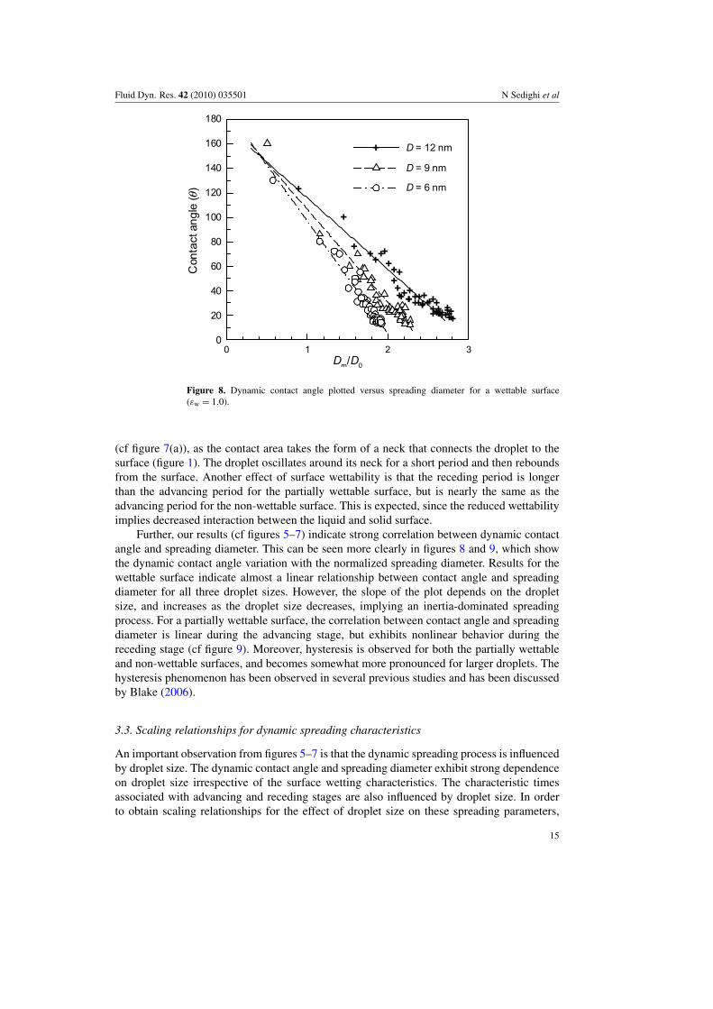
Figure 8. Dynamic contact angle plotted versus spreading diameter for a wettable surface(εw = 1.0).
(cf figure 7(a)), as the contact area takes the form of a neck that connects the droplet to thesurface (figure 1). The droplet oscillates around its neck for a short period and then reboundsfrom the surface. Another effect of surface wettability is that the receding period is longerthan the advancing period for the partially wettable surface, but is nearly the same as theadvancing period for the non-wettable surface. This is expected, since the reduced wettabilityimplies decreased interaction between the liquid and solid surface.
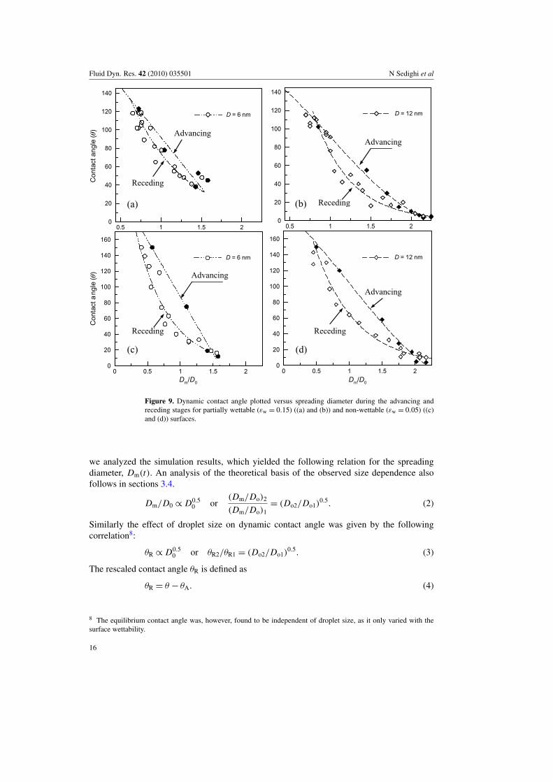
Further, our results (cf figures 5–7) indicate strong correlation between dynamic contactangle and spreading diameter. This can be seen more clearly in figures 8 and 9, which showthe dynamic contact angle variation with the normalized spreading diameter. Results for thewettable surface indicate almost a linear relationship between contact angle and spreadingdiameter for all three droplet sizes. However, the slope of the plot depends on the dropletsize, and increases as the droplet size decreases, implying an inertia-dominated spreadingprocess. For a partially wettable surface, the correlation between contact angle and spreadingdiameter is linear during the advancing stage, but exhibits nonlinear behavior during thereceding stage (cf figure 9). Moreover, hysteresis is observed for both the partially wettableand non-wettable surfaces, and becomes somewhat more pronounced for larger droplets. Thehysteresis phenomenon has been observed in several previous studies and has been discussedby Blake (2006).
3.3. Scaling relationships for dynamic spreading characteristics
An important observation from figures 5–7 is that the dynamic spreading process is influencedby droplet size. The dynamic contact angle and spreading diameter exhibit strong dependenceon droplet size irrespective of the surface wetting characteristics. The characteristic timesassociated with advancing and receding stages are also influenced by droplet size. In orderto obtain scaling relationships for the effect of droplet size on these spreading parameters,
15
Fluid Dyn. Res. 42 (2010) 035501 N Sedighi et al
0.5 1 1.5 20
20
40
60
80
100
120
140
0.5 1 1.5 20
20
40
60
80
100
120
140
D = 12 nm
Receding
Advancing
(b)
0 0.5 1 1.5 20
20
40
60
80
00
20
40
60
Dm/D0Dm/D0
0 0.5 1 1.5 20
20
40
60
80
100
120
140
160
D = 12 nm
Receding
Advancing
(d)
0.5 1 1.5 20
20
40
60
80
100
120
140
0.5 1 1.5 20
20
40
60
80
100
120
140
D = 6 nm
Receding
Advancing
(a)
0 0.5 1 1.5 20
20
40
60
80
100
120
140
160
Con
tact
angl
e(θ
)C
onta
ctan
gle
(θ)
0 0.5 1 1.5 20
20
40
60
80
100
120
140
160
D = 6 nm
jgk.jgk.
Receding
Advancing
(c)
Figure 9. Dynamic contact angle plotted versus spreading diameter during the advancing andreceding stages for partially wettable (εw = 0.15) ((a) and (b)) and non-wettable (εw = 0.05) ((c)and (d)) surfaces.
we analyzed the simulation results, which yielded the following relation for the spreadingdiameter, Dm(t). An analysis of the theoretical basis of the observed size dependence alsofollows in sections 3.4.
Dm/D0 ∝ D0.50 or
(Dm/Do)2
(Dm/Do)1= (Do2/Do1)
0.5. (2)
Similarly the effect of droplet size on dynamic contact angle was given by the followingcorrelation8:
θR ∝ D0.50 or θR2/θR1 = (Do2/Do1)
0.5. (3)
The rescaled contact angle θR is defined as
θR = θ − θA. (4)
8 The equilibrium contact angle was, however, found to be independent of droplet size, as it only varied with thesurface wettability.
16
Fluid Dyn. Res. 42 (2010) 035501 N Sedighi et al
Here θA is the contact angle at the end of advancing period. The scaling for the dynamiccontact angle is based on the consideration that the contact angle exhibits a linear relationshipwith the spreading diameter, especially in the advancing stage. The above correlations werefound to hold for the three wettable, partially wettable and non-wettable surfaces investigated.Further, the simulations yielded the following correlation for the advancing and receding timeperiods:
t ∝ D2/30 or t2/t1 = (Do2/Do1)
2/3. (5)
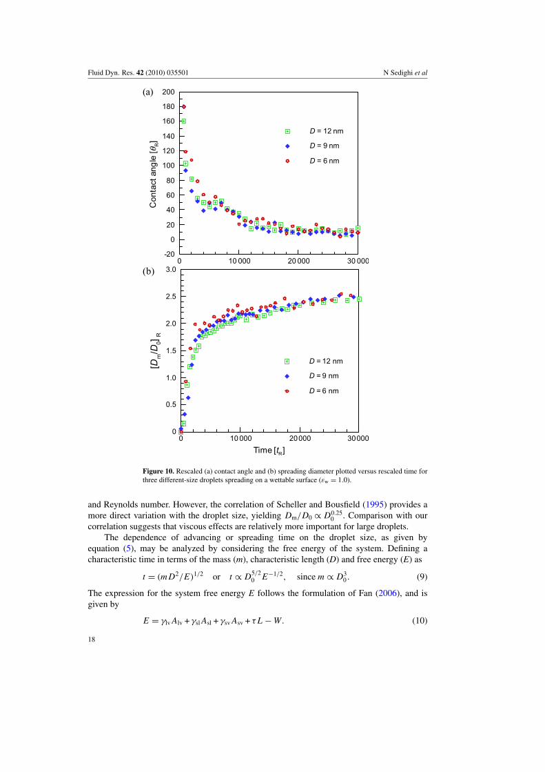
Subscript 1 in the above equations refers to the 12 nm droplet. Note that a similar timedependence was obtained for Dm/Do in section 3.1. Figures 10–12 present the observedresults for rescaled contact angle and spreading diameter (based on equations (2) and (3))plotted versus the rescaled time (equation (5)) for the wettable, partially wettable and non-wettable surfaces, respectively. These plots clearly demonstrate the validity of the abovecorrelations, except for some variances during the receding stage for the partially wettableand non-wettable surfaces. For comparison these rescaled plots should be compared withfigures 5–7 on a one–one basis.
3.4. Additional analysis of scaling relationships
An attempt was also made to provide the physical basis and further validation for the abovescaling relationships. One can obtain a scaling relation for the spreading diameter by assumingthat during spreading the droplet shape changes from a sphere to a flattened sphere, and in thisprocess the droplet kinetic energy is dissipated by viscous effects. This yields the following:
ρD30 V 2
0 ∝ µ(V0/h)D3m, (6)
where h is the thickness of the flattened drop corresponding to its maximum spreadingposition. Using the conservation of volume during this process, i.e. D3
0 ∝ h D2m, yields the
scaling relation as Dm/Do ∝ Re1/5, as discussed in Chandra and Avedisian (1991) andRein (1993), or Dm/Do ∝ D1/5
o . Since the present simulations indicate Dm/Do ∝ D1/2o , the
viscous effects may not be as significant for sub-micron droplets, especially for partiallywettable and non-wettable surfaces. Therefore, assuming that the droplet spreading processis analogous to the stretching and recoiling of a spring, and its kinetic energy is converted tosurface energy (Richard et al 2002) yields
ρD30 V 2
0 ≡ γ D2m (7)
Since the liquid density and initial droplet velocity were kept the same for different dropletsizes investigated, this leads to the correlation given by equation (2), i.e.
Dm/D0 ∝ D0.50
(Dm/Do)2
(Dm/Do)1= (Do2/Do1)
0.5. (8)
Thus, the present MD results indicate that the hypothesis based on surface energy is moremeaningful than that based on viscous dissipation for the spreading of nano-size droplets. Itis also important to compare our correlations with those reported in the literature. Sikaloet al (2002) reported experimental data for isopropanol droplets with diameters of 3.3 and1.8 mm, which indicated a smaller spreading diameter for the smaller droplet. However,they suggested that the viscous effect is more important. Previous studies have reportedcorrelations for the maximum spreading diameter for macroscopic droplets. Several of thesecorrelations are listed in table 1 of Bathel et al (2007). It is difficult, however, to compareour results with those in table 1, since the droplet diameter is embedded in the Weber number
17
Fluid Dyn. Res. 42 (2010) 035501 N Sedighi et al
Con
tact
angl
e[θ
R]
0 10 000 20 000 30 000-20
0
20
40
60
80
100
120
140
160
180
200
D = 12 nm
D = 9 nm
D = 6 nm
(a)
Time [tR]
[Dm/D
0]R
0 10 000 20000 300000
0.5
1.5
2.5
D = 12 nm
D = 9 nm
D = 6 nm
(b) 3.0
2.0
1.0
+
+
+
++
++ +
++ +
+
++
+ ++
++ +
+ + + + + + + + + + +
+
+
+
+
+
++
+
++++++++++++++
++ + + + + + +
+ + + + + + +
+
Figure 10. Rescaled (a) contact angle and (b) spreading diameter plotted versus rescaled time forthree different-size droplets spreading on a wettable surface (εw = 1.0).
and Reynolds number. However, the correlation of Scheller and Bousfield (1995) provides amore direct variation with the droplet size, yielding Dm/D0 ∝ D0.25
0 . Comparison with ourcorrelation suggests that viscous effects are relatively more important for large droplets.
The dependence of advancing or spreading time on the droplet size, as given byequation (5), may be analyzed by considering the free energy of the system. Defining acharacteristic time in terms of the mass (m), characteristic length (D) and free energy (E) as
t = (m D2/E)1/2 or t ∝ D5/20 E−1/2, since m ∝ D3
0 . (9)
The expression for the system free energy E follows the formulation of Fan (2006), and isgiven by
E = γlv Alv + γsl Asl + γsv Asv + τ L − W. (10)
18
Fluid Dyn. Res. 42 (2010) 035501 N Sedighi et al
Con
tact
angl
e(θ
R)
0 10000 20000 30000
0
25
50
75
100
125
150
175
200
D = 12 nm
D = 9 nm
D = 6 nm
(a)
Time (tR)
[Dm/D
0]R
0 10 000 20 000 30 0000
0.5
1.0
1.5
2.0
2.5
3.0
D = 12 nm
D = 9 nm
D = 6 nm
(b)
+
+
+
+
++ + + + + + + + +
+ ++ + + +
+
+ ++ + +
+ ++
++
+
+
+
+
++
+++
++
++ +
+ ++
++
++
+ ++
++
+
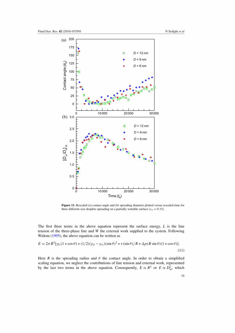
Figure 11. Rescaled (a) contact angle and (b) spreading diameter plotted versus rescaled time forthree different-size droplets spreading on a partially wettable surface (εw = 0.15).
The first three terms in the above equation represent the surface energy, L is the linetension of the three-phase line and W the external work supplied to the system. FollowingWidom (1995), the above equation can be written as
E = 2π R2[γlv(1 + cos θ) + (1/2)(γsl − γsv)(sin θ)2 + τ(sin θ)/R + 1p(R sin θ)(1 + cos θ)].
(11)
Here R is the spreading radius and θ the contact angle. In order to obtain a simplifiedscaling equation, we neglect the contributions of line tension and external work, representedby the last two terms in the above equation. Consequently, E ∝ R2 or E ∝ D2
m, which
19
Fluid Dyn. Res. 42 (2010) 035501 N Sedighi et al
Con
tact
angl
e(θ
R)
0 10000 20 000 30000–20
0
20
40
60
80
100
120
140
160
180
200
D = 12 nm
D = 9 nm
D = 6 nm
(a)
Time (tR)
[Dm/D
0]R
0 10 000 20 000 30 0000
0.5
1.5
2.5
3.0
2.0
1.0
D = 12 nm
D = 9 nm
D = 6 nm
(b)
+
+
+
++
+ ++ + +
+ + ++
++
++ +
+
++
++
+ +
+
+
+
+
+
+
++
+ ++ + +
+ + +
++
++
++ +
++ +
+ +
+
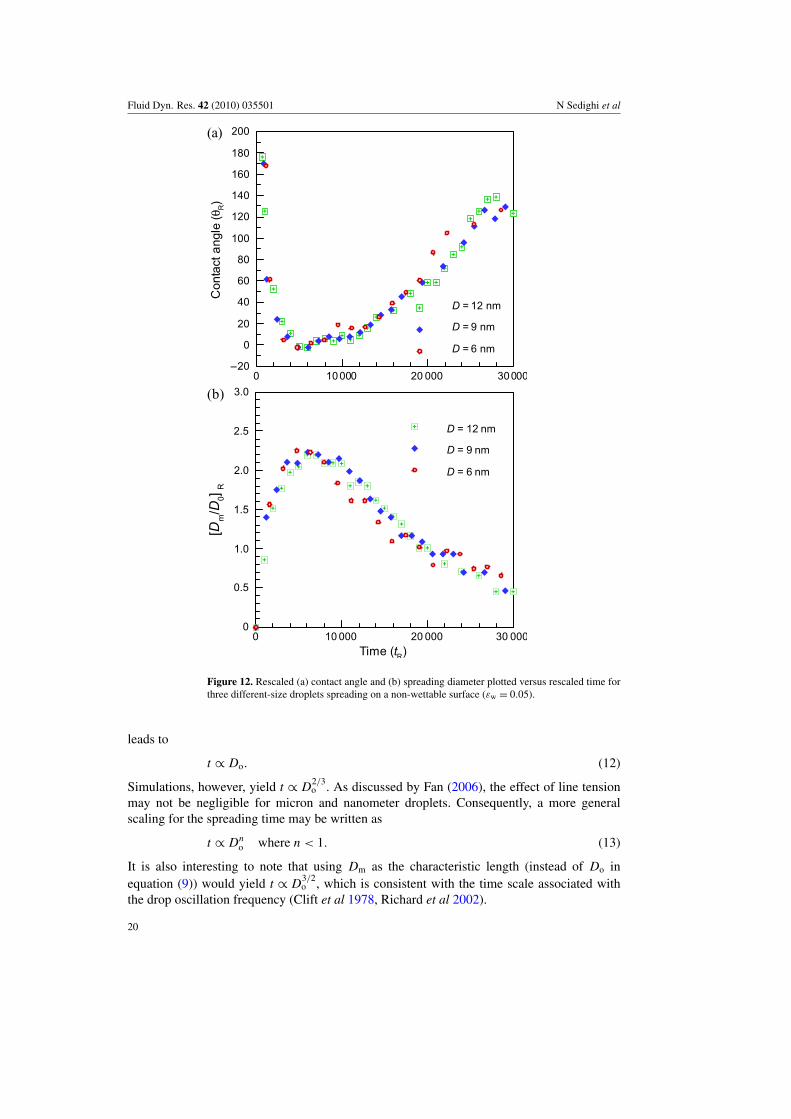
Figure 12. Rescaled (a) contact angle and (b) spreading diameter plotted versus rescaled time forthree different-size droplets spreading on a non-wettable surface (εw = 0.05).
leads to
t ∝ Do. (12)
Simulations, however, yield t ∝ D2/3o . As discussed by Fan (2006), the effect of line tension
may not be negligible for micron and nanometer droplets. Consequently, a more generalscaling for the spreading time may be written as
t ∝ Dno where n < 1. (13)
It is also interesting to note that using Dm as the characteristic length (instead of Do inequation (9)) would yield t ∝ D3/2
o , which is consistent with the time scale associated withthe drop oscillation frequency (Clift et al 1978, Richard et al 2002).
20
Fluid Dyn. Res. 42 (2010) 035501 N Sedighi et al
4. Conclusions
MD simulations have been performed to investigate the spreading behavior of nano-sizedroplets impinging on flat surfaces. The effect of droplet size on spreading dynamics has beencharacterized for wettable, partially wettable and non-wettable surfaces. The computationalmodel has been validated through a qualitative comparison with the measurements of Bayerand Megaridis (2006), and comparison with existing correlations. The comparison withmeasurements, based on the ratio of the relevant time scales, also indicates that for theconditions investigated, the spreading dynamics is governed by the inertial and surface forces,with negligible influence of the viscous forces.
Results indicate that the spreading dynamics is strongly influenced by the droplet size.The dynamic contact angle and spreading diameter, as well as the advancing and recedingtime periods, exhibit strong dependence on droplet size irrespective of the surface wettingcharacteristics. Simulation results have been analyzed to develop correlations for the effectof droplet size on these spreading parameters. The correlations indicate that the normalizedspreading diameter and contact angle scale with drop diameter as Dm/D0 ∝ D0.5
0 and θR ∝
D0.50 , while the advancing and receding time periods scale as t ∝ D2/3
0 . We have also usedglobal energy considerations to provide a physical basis for these correlations.
While the present simulations for nano-size droplets exhibit good qualitative andreasonable semi-quantitative comparison with measurements for continuum-size droplets,additional experimental and computational studies are needed to provide more quantitativevalidation for the correlations developed in the present study. Experimental studies shouldfocus on providing time-resolved measurements of the spreading process for micron- andnano-size droplets, while MD simulations should consider more realistic fluids and surfaces,as well as larger droplets.
Acknowledgments
We thank Professor Ludwig Nitsche for helpful discussions. SM was supported in part froma grant from the Office of Basic Energy Sciences, US Department of Energy (DE-FG02-08ER46538)
References
Allen M P and Tildesley D J 1987 Computer Simulation of Liquids (Oxford: Clarendon)Asai A, Shiova M, Hirasawa S and Okazaki T 1993 Impact of an ink drop on paper J. Imaging Sci. Technol.
37 205–7Attinger D, Zhao Z and Poulikakos D 2000 An experimental study of molten microdroplet surface deposition and
solidification: transient behavior and wetting angle dynamics J. Heat Transfer 122 544–56Aziz S D and Chandra S 2000 Impact, recoil and splashing of molten metal droplets Int. J. Heat Mass Transfer 43
2841–57Bathel B F, Stephen N, Johnson L and Ratner A 2007 Prediction of postcontact parameters of fluid droplet impact on
a smooth surface AIAA J. 45 1725–33Bayer I S and Megaridis C M 2006 Contact angle dynamics in droplets impacting on flat surfaces with different
wetting characteristics J. Fluid Mech. 558 415–49Blake T D 2006 The physics of moving wetting lines J. Colloid Interface Sci. 299 1–13Blake T D and Haynes J M 1969 Kinetics of liquid/liquid displacement J. Colloid Interface Sci. 30 421–3Boland T, Tao X, Damon B J, Manley B, Kesari P, Jalota S and Bhadur S 2007 Drop-on-demand printing of cells and
materials for designer tissue constructs Mater. Sci. Eng. C 27 372–6Cazabat A M, Fraysse N and Heslot F 1990 Molecular wetting films Prog. Colloid Polym. Sci. 83 52–5Chandra S and Avedisian C T 1991 On the collision of a droplet with solid surface Proc. R. Soc. A 432 13–41
21
Fluid Dyn. Res. 42 (2010) 035501 N Sedighi et al
Cherry B W and Holmes C M 1969 Kinetics of wetting of surfaces by polymers J. Colloid Interface Sci. 29 174–6Choi T Y, Poulikakos D and Grigoropoulos C P 2004 Fountain-pen-based laser microstructuring with gold
nanoparticle inks Appl. Phys. Lett. 85 13–5Clift R, Grace J R and Weber M E 1978 Bubbles, Drops and Particles (New York: Academic Press)Cox R G 1986 The dynamics of the spreading of liquids on a solid surface J. Fluid Mech. 168 169–94Crooks R, Cooper-White J and Boger D V 2001 The role of dynamic surface tension and elasticity on the dynamics
of drop impact Chem. Eng. Sci. 56 5575–92De Coninck J, D’Ortona U, Koplik J and Banavar J 1995 Terraced spreading of chain molecules via molecular
dynamics Phys. Rev. Lett. 74 928–31De Coninck J, De Ruijter M J and Voue M 2001 Dynamics of wetting Curr. Opin. Colloid Interface Sci. 6 49–53de Gennes P G 1985 Wetting: statics and dynamics Rev. Mod. Phys. 57 827–63Delplanque J P and Rangel R H 1997 An improved model for droplet solidification on a flat surface J. Mater. Sci. 32
1519–30Dong H, Carr W W and Morris J F 2006 Visualization of drop-on-demand inkjet: drop formation and deposition
Rev. Sci. Instrum. 77 085101Dussan E B 1979 On the spreading of liquid on solid surface: static and dynamic contact angle Ann. Rev. Fluid Mech.
11 371–400Fan H 2006 Liquid droplet spreading with line tension effect J. Phys.: Condens. Matter 18 4481–8Graham-Rowe D 2007 Medicine—Ultrasonic tourniquet Technol. Rev. 109 15Heine D R, Grest G S and Webb E B III 2003 Spreading dynamics of polymer nanodroplets Phys. Rev. E 68
061603Heslot F, Fraysse N and Cazabat A M 1989 Molecular layering in the spreading of wetting liquid drops Nature 338
640–2Hoffman R H 1975 A study of the advancing interface 1. interface shape in liquid-gas systems J. Colloid Interface
Sci. 50 228–41Kim H Y, Park S Y and Min K 2003 Imaging the high-speed impact of microdrop on solid surface Rev. Sci. Instrum.
74 4930–7Lee D H, Chang Y J, Herman G S and Chang C H 2007 A general route to printable high-mobility transparent
amorphous oxide semiconductors Adv. Mater. 19 843–7Lee J and Kim C J 2000 Surface-tension-driven microactuation based on continuous electrowetting J.
Microelectromech. Syst. 9 2 171–80Mao T, Kuhn D C S and Tran H 1997 Spread and rebound of liquid droplets upon impact on flat surfaces AIChE J.
43 2169–79Ok H, Park H, Carr W W, Morris J F and Zhu J 2004 Particle-laden drop impacting on solid surfaces J. Dispers. Sci.
Technol. 25 449–56Pasandideh-Fard M, Qiao Y M, Chandra S and Mostaghimi J 1996 Capillary effects during droplet impact on a solid
surface Phys. Fluids 8 650–9Pede D, Serra G and De Rossi D 1998 Microfabrication of conducting polymer devices by ink-jet stereolithography
Mater. Sci. Eng. C 5 289–91Rein M 1993 Phenomena of liquid drop impact on solid and liquid surface Fluid Dyn. Res. 12 61–93Richard D, Clanet C and Quere D 2002 Surface phenomena—contact time of a bouncing drop Nature 417 811Rioboo R, Marengo M and Tropea C 2002 Time evolution of liquid drop impact onto solid, dry surfaces Exp. Fluids
33 112–4de Ruijter M, Blake T D, Clarke A and De Coninck J 1999 Droplet spreading: a tool to characterize surfaces at the
microscopic scale J. Petrol. Sci. Eng. 24 189–98Scheller B and Bousfield D W 1995 Newtonian drop impact with a solid surface AIChE J. 41 1357–67Sedighi N, Murad S and Aggarwal S K 2009 Molecular dynamics simulations of nano-droplet wetting on a solid
surface Atom. Sprays 19 11–5Shikhmurzaev Y D 1997 Moving contact lines in liquid/liquid/solid systems J. Fluid Mech. 334 211–49Sikalo S, Marengo M, Tropea C and Ganic E N 2002 Analysis of impact of droplets on horizontal surfaces Exp.
Therm. Fluid Sci. 25 503–10Starov V M, Zhdanov S A and Velarde M G 2002 Spreading of liquid drops over thick porous layers: complete
wetting case Langmuir 18 9744–50Tanner L H 1979 Spreading of silicone oil drops on horizontal surfaces J. Phys. D: Appl. Phys. 12 1473–84Van Dam D B and Le Clerc C 2004 Experimental study of the impact of an ink-jet printed droplet on a solid substrate
Phys. Fluids 16 3403–14Voue M, De Coninck J, Villette S, Valignat M P and Cazabat A M 1998a Investigation of layered microdroplets using
ellipsometric techniques Thin Solid Films 313–314 819–24
22

Fluid Dyn. Res. 42 (2010) 035501 N Sedighi et al
Voue M, Valignat M P, Oshanin G, Cazabat A M and De Coninck J 1998b Dynamics and spreading of liquidmicrodroplets on substrates of increasing surface energy Langmuir 14 5951–8
Widom B 1995 Line tension and the shape of a sessile drop J. Phys. Chem. 99 2803–6Yang J X, Koplik J and Banavar J 1991 Molecular dynamics of drop spreading on a solid surface Phys. Rev. Lett. 67
3539–42Yang W J 1995 Theory on vaporization and combustion of liquid drops of pure substances and binary mixtures on
heated surfaces Technical Report 535 Institute of Space and Aeronautical Science, University of TokyoYarin A L 2006 Drop impact dynamics: splashing, spreading, receding, bouncing Ann. Rev. Fluid Mech. 38 159–92Zhao Z, Poulikakos D and Fukai J 1996 Heat transfer and fluid dynamics during the collision of a liquid droplet on a
substrate 1. Modeling Int. J. Heat Mass Transfer 39 2771–89
23


![Rotational energy relaxation quantum dynamics of a …The rotational energy relaxation (RER) of a molecule X 2( j,m j)ina 4He superfluid nanodroplet [HeND or (4He) N; T = 0.37 K] has](https://static.fdocuments.us/doc/165x107/5f0f5e3a7e708231d443cff8/rotational-energy-relaxation-quantum-dynamics-of-a-the-rotational-energy-relaxation.jpg)