Molding Filling and Temperature Simulation of Continuous...
12
CCC Annual Report UIUC, August 20, 2014 Hai Hao 1 , Muyi LI 1 , Lance Hibbeler 2 , Brian Thomas 2 1 School of Materials Science & Engineering Dalian University of Technology, China 2 Department of Mechanical Science & Engineering University of Illinois at Urbana-Champaign Molding Filling and Temperature Simulation of Continuous Casting University of Illinois at Urbana-Champaign • Metals Processing Simulation Lab • Hai Hao • 2 Objectives • Explore mold filling and thermo-mechanical behavior of a typical slab mold during startup. – First step: Use ProCAST to simulate coupled heat flux, temperature and fluid flow during the filling stage of continuous casting – Enable subsequent calculations of thermal distortion, which affects mold taper and may cause problems such as breakouts and cracks.
Transcript of Molding Filling and Temperature Simulation of Continuous...

CCC Annual ReportUIUC, August 20, 2014
Hai Hao1, Muyi LI1, Lance Hibbeler2, Brian Thomas2
1School of Materials Science & EngineeringDalian University of Technology, China
2Department of Mechanical Science & Engineering
University of Illinois at Urbana-Champaign
Molding Filling and Temperature
Simulation of Continuous Casting
University of Illinois at Urbana-Champaign • Metals Processing Simulation Lab • Hai Hao • 2
Objectives
• Explore mold filling and thermo-mechanical behavior of atypical slab mold during startup.– First step: Use ProCAST to simulate coupled heat flux,
temperature and fluid flow during the filling stage of continuouscasting
– Enable subsequent calculations of thermal distortion, whichaffects mold taper and may cause problems such asbreakouts and cracks.

University of Illinois at Urbana-Champaign • Metals Processing Simulation Lab • Hai Hao • 3
Outline
• The application of ProCAST in continuous casting
• Geometry, materials properties and boundary conditions in the model
• Thermal and fluid simulation • Heat flux results • Temperature results• References
University of Illinois at Urbana-Champaign • Metals Processing Simulation Lab • Hai Hao • 4
The application of ProCAST in the continuous casting
ProCAST is a commercial software using theFinite Elements Method (FEM). It allows thesteady/none-steday state modeling of thermal heattransfer (heat flow), fluid flow, including mold filling,stresses fully coupled with the thermal solution.
ProCAST provides a very prominent fluid flowequation to simulate the filling of mold, which iscomplete Navier-Stokes flow equations coupled with
3-D energy equation. Actions of fluid free surface iscontrolled by volume of fluid method(VOF). These
make it able to simulate accurate thermal and fluidresults during the entire process of filling.

University of Illinois at Urbana-Champaign • Metals Processing Simulation Lab • Hai Hao • 5
The application of ProCAST in the continuous casting
Using none-steady calculations in this case to model start-up thermal behaviors of the continuous casting .
The calculations use MILE algorithm (Mixed Lagrangian-Eulerian), an accordion should be established to introduce new layers of elements.
University of Illinois at Urbana-Champaign • Metals Processing Simulation Lab • Hai Hao • 6
Mold Geometry
Units: mm
Cut plane
Ref. (3)

University of Illinois at Urbana-Champaign • Metals Processing Simulation Lab • Hai Hao • 7
Cp(J/Kg·K)
λ(w/m·K)
Initial T(℃)
Density (Kg/m3)
Melting point(℃)
dynamic viscosity(Kg/m·s)
Latent heat(KJ/Kg)
Mold-CuCrZr
385 350 30 8900
steel 661 33 1550 7400 1495 0.006 272
Material properties
University of Illinois at Urbana-Champaign • Metals Processing Simulation Lab • Hai Hao • 8
Model Domain and Mesh
•To lessen calculation, the model is ¼of the real mold.
•This mesh has total 126692 elementsand 31260 nodes.
•Elements size range from 2mm to20mm in both mold and steel regions.
•5 elements through the thickness ofthe mold wall
•Assume Reduced Order Model(ROM) to simulate mold asrectangular block, with slots as BCs.

University of Illinois at Urbana-Champaign • Metals Processing Simulation Lab • Hai Hao • 9
• Heat transfer coefficient tocooling water from HibbelerRef.(1) – see Figure.
• Heat transfer coefficient fromROM mold wall ~60 kW/m2K
• Heat flux across the interfacialgap between steel shell andmold, qint, is given by an effectiveheat-transfer coefficient (hgap)between the surface temperatureof the steel shell (Ts) and the hotface of the mold wall (Thot), hgap
according to formula 1. (FromHibbeler Ref.(1), and MengRef.(4))
)(int hotsgap TThq −= formula 1
Boundary conditions
1000 1100 1200 1300 1400 1500 1600
2000
4000
6000
h-ga
p (w
/m2 .K
)
Ts (OC)
h-gap
University of Illinois at Urbana-Champaign • Metals Processing Simulation Lab • Hai Hao • 10
Casting parameters
0 5 10 15 20 25 300
10
20
30
40
50
60
No
zzle
Flo
w R
ate
(Kg/
s)
Time (s)
Nozzle Flow Rate
flow rate (kg/s) entering the domain through the nozzle vs. time
0 10 20 30
0
10
20
30
Ca
stin
Spe
ed
(mm
/s)
Time (s)
Castin Speed
Casting speed vs time
From Hibbeler, ECCC, 2014, Ref. (2)

University of Illinois at Urbana-Champaign • Metals Processing Simulation Lab • Hai Hao • 11
Thermal and fluid simulation
Wide face
• The simulation of filling in the wide face are shown in the right.
• The simulation time of 30s need 10 hours CPU time.
University of Illinois at Urbana-Champaign • Metals Processing Simulation Lab • Hai Hao • 12
Instantaneous liquid level profiles during mold filling
t=0 t=5s
t=15s t=25s
t=10s
t=30s
University of Illinois at Urbana-Champaign • Metals Processing Simulation Lab • Hai Hao • 13
Liquid Level History Results
Simulated averageliquid level isvalidated by matchwith average fromHibbeler, Ref. (2)
Average liquid level is integrated volume fraction over entire domain.
Level on the NF wall has delay for filling before rising quickly
Almost stable level during latter stages of filling
0 5 10 15 20 25 301200
1000
800
600
400
200
0
Dis
tanc
e B
elo
w T
op
of t
he
Mol
d z
(m
m)
Time (s)
orange line in Lance Hibbeler Fig 7 of ECCC paper liquid level on the NF wall average liquid level
Liquid level touched the wide face
University of Illinois at Urbana-Champaign • Metals Processing Simulation Lab • Hai Hao • 14
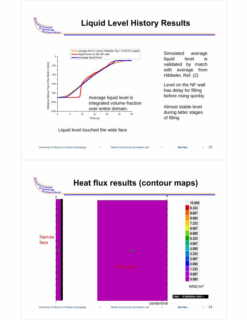
Heat flux results (contour maps)
centerline
Wide face
MW/m2
Narrow face

University of Illinois at Urbana-Champaign • Metals Processing Simulation Lab • Hai Hao • 15
0 1 2 3 4 5 6 7 8
1000
800
600
400
200
0 t=10s t=15s t=20s t=25s
Dis
tan
ce b
elo
w to
p o
f mo
ld(m
m)
Heat flux qhot
in narrow hot face center during startup(Mw/m2)
simulate by ProCAST
Heat flux results (profiles down NF)
• Heat flux region logically follows rising liquid level.
• At t=10s during initial stages of filling, heat flux is almost uniform down mold walls. Except, liquid level fluctuates, causing small heat flux variations at the narrow face
• Later, peak heat flux is found at liquid level, and drops slightly with distance below.
University of Illinois at Urbana-Champaign • Metals Processing Simulation Lab • Hai Hao • 16
Heat flux results
• The graphs are comparison between simulated narrow-face center heat flux results and data mentioned in the paper.
• Heat flux was obtained along the centerline of hot narrow-face nodes.
0 1 2 3 4 5 6 7 8
1000
800
600
400
200
0
Dis
tanc
e be
low
top
of
mol
d(m
m)
Heat Flux in hot narow face (MW/m2)
t=10s
0 1 2 3 4 5 6 7 8
1000
800
600
400
200
0
Dis
tanc
e be
low
top
of
mol
d(m
m)
Heat Flux in hot narow face (MW/m2)
t=15s

University of Illinois at Urbana-Champaign • Metals Processing Simulation Lab • Hai Hao • 17
Heat flux results
0 1 2 3 4 5 6 7 8
1000
800
600
400
200
0
Dis
tanc
e be
low
top
of
mol
d(m
m)
Heat Flux in hot narow face (MW/m2)
t=20s
0 1 2 3 4 5 6 7 8
1000
800
600
400
200
0
Dis
tanc
e be
low
top
of
mol
d(m
m)
Heat Flux in hot narow face (MW/m2)
t=25s
University of Illinois at Urbana-Champaign • Metals Processing Simulation Lab • Hai Hao • 18
Heat flux results
0 5 10 15 20 25 300.0
0.5
1.0
1.5
2.0
2.5
3.0
aver
age
heat
flu
x in
nar
row
fac
e ce
nter
(MW
/m2)
Time (s)
0 5 10 15 20 25 300.0
0.5
1.0
1.5
2.0
2.5
3.0
3.5
4.0
4.5
5.0
aver
age
heat
flux
in w
ide
face
cen
ter(
MW
/m2
)
Time (s)
Average heat flux results are evaluated as integral average.The parameters used in the model such as hwater , watertemperature are applied for steady state during continuouscasting (From Hibbeler, ECCC, 2014, Ref. (2)).
Hot face heat flux
Narrow face Wide face

University of Illinois at Urbana-Champaign • Metals Processing Simulation Lab • Hai Hao • 19
Cold face heat flux
Measured Simulated by ProCAST
0 10 20 30-0.10
-0.05
0.00
0.05
0.10
0.15
0.20
hea
t flu
x (M
w/m
2 )
Time from start of casting (s)
N-plate Heat flux W-plate Heat flux
Heat flux results
0 5 10 15 20 25 300.00.20.40.60.81.01.21.41.61.82.02.22.4
aver
age
heat
flux
(M
W/m
2)
Time (s)
narrow face wide face
NF NF
WF WF
University of Illinois at Urbana-Champaign • Metals Processing Simulation Lab • Hai Hao • 20
Temperature results
900mm
Thermocouple locations
Narrow face
From Hibbeler, Metrans. B, 2012, Ref. (1)0 5 10 15 20 25 30
20
30
40
50
60
70
80
90
100
110
120
Tm
pera
ture
(o C
)
Time (s)
Measured TC3 temperature Simulated Temperature in TC3 location
0 5 10 15 20 25 3020
30
40
50
60
70
80
90
100
110
120
Tm
pera
ture
(o C
)
Time (s)
Measured TC2 temperature Simulated Temperature in TC2 location

University of Illinois at Urbana-Champaign • Metals Processing Simulation Lab • Hai Hao • 21
Temperature results
0 5 10 15 20 25 3020
30
40
50
60
70
80
90
100
110
120
Tm
per
atu
re (
o C)
Time (s)
Measured TC4 temperature Simulated temperature in TC4 location
0 5 10 15 20 25 3020
30
40
50
60
70
80
90
100
110
120
Tm
pera
ture
(o C
)
Time (s)
Measured TC5 temperature Simulated Temperature in TC5 location
0 5 10 15 20 25 3020
30
40
50
60
70
80
90
100
110
120
Tm
pera
ture
(o C
)
Time (s)
Measured TC6 temperature Simulated Temperature in TC6 location
0 5 10 15 20 25 3020
30
40
50
60
70
80
90
100
110
120
Tm
pera
ture
(o C
)
Time (s)
Measured TC7 temperature Simulated Temperature in TC7 location
0 5 10 15 20 25 3020
30
40
50
60
70
80
90
100
110
120
Tm
pera
ture
(o C
)
Time (s)
Measured TC8 temperature Simulated Temperature in TC8 location
University of Illinois at Urbana-Champaign • Metals Processing Simulation Lab • Hai Hao • 22
0 5 10 15 20 25 300
5
10
15
20
25
30
she
ll th
ickn
ess
(mm
)
t (s)
mold exit
0.3 fraction solid is the definition of shell thickness
1494.40 1494.45 1494.500.0
0.5
1.0
solid
fra
ctio
n
T(oC)
0 10 20 300
5
10
15
20
25
30
shel
l thi
ckne
ss (
mm
)
t (s)
mold middle
Shell thickness results

University of Illinois at Urbana-Champaign • Metals Processing Simulation Lab • Hai Hao • 23
Conclusions
• ProCAST could be applied to simulate the startup phase of continuous casting.
• The heat flux results on mold hot face are comparatively consistent with water-heatupmeasurements.
• The temperature results are comparatively consistent with the TC measurements.
• Simulation results are useful to carry out subsequent calculations of thermal distortion on mold.
University of Illinois at Urbana-Champaign • Metals Processing Simulation Lab • Hai Hao • 24
References
1. L.C. Hibbeler et al., The Thermal Distortion of a Funnel Mold. Metallurgical and Materials Transactions B, 2012. 43(5): p. 1156-1172.
2. L.C. Hibbeler et al., Simulation and online measurement of narrow face mold Distortion in Thin-slab casting. ECCC 2014 (European Continuous Casting Conference, Graz, Austria, June 23-26, 2014).
3. H.H. Visser et al., Implementation of four port submerged entry nozzle to improve the stability of the thin slab casting process at the ijmuiden dsp plant.
4. Y.T. Meng et al., Heat-transfer and solidification model of continuous slab casting: CON1D. Metallurgical and Materials Transactions B, 2003. 34(5): p. 685 - 705.