Mold Tooling Design - CATIA designcatiadesign.org/_doc/v5r14/catpdfmtdug_C2/mtdug.pdf · Overview...
271
Mold Tooling Design Overview What's New? Getting Started Entering the Mold Design Workbench Retrieving Part Defining the Mold Base Splitting the Core and the Cavity Inserting Components Positioning Ejector Pins on a Mold Base Creating a Gate Creating a Runner Creating a Coolant Channel Saving Data User Tasks Preparing the Part to Mold Creating a Mold Base Creating a User-defined Mold Base Creating a Standard Mold Base Adding a Plate Adding an Insert Standard Mold Components Component Parameters Adding Components Contextual Menu of Components User Component Requirements Positioning a Slider Replacing Components Copying a Component Reference Splitting Components Adding or Removing Material around a Component Modifying the Geometry of Components Injection features Gates Runners Coolant Channels Holes Analyze Holes in Plates Explode Holes Drilling Components Drilling Lists
Transcript of Mold Tooling Design - CATIA designcatiadesign.org/_doc/v5r14/catpdfmtdug_C2/mtdug.pdf · Overview...

Mold Tooling Design
Overview
What's New?
Getting Started
Entering the Mold Design Workbench Retrieving Part Defining the Mold Base Splitting the Core and the Cavity Inserting Components Positioning Ejector Pins on a Mold Base Creating a Gate Creating a Runner Creating a Coolant Channel Saving Data
User Tasks
Preparing the Part to Mold Creating a Mold Base
Creating a User-defined Mold Base Creating a Standard Mold Base Adding a Plate Adding an Insert
Standard Mold Components Component Parameters Adding Components Contextual Menu of Components User Component Requirements Positioning a Slider Replacing Components Copying a Component Reference Splitting Components Adding or Removing Material around a Component Modifying the Geometry of Components
Injection features Gates Runners Coolant Channels
Holes Analyze Holes in Plates Explode Holes Drilling Components Drilling Lists

Catalogs Adding your Catalog Linking your Catalog to Another Using your Catalog
Generating the Bill of Material Saving Data Using other Workbenches
Mold Kinematics Checking Clash and Clearance Using Drafting Functionalities Using Prismatic Machining Functionalities Using Surface Machining Functionalities
Mold Tooling Design Workbench Description
Menu Bar Tool Bars
Mold Base Components Guiding Components Locating Components Fixing Components Ejection Components Injection Components Miscellaneous Components Manipulation Drill Tools
Specification Tree
Customizing
General Component
Methodology
Inserting a Loose Core Using a Rule Using Assembled Components
Glossary
Index

Overview
Welcome to the Mold Tooling Design User's Guide! This guide is intended for users who need to become quickly familiar with the product. This manual also covers the needs of the P1 Tooling Design application. Functions that are specific to Mold Tooling Design and therefore not available to Tooling Design users are indicated by either this
image in the left hand margin or this image at the top of the page .
This overview provides the following information:
● Mold Tooling Design in a Nutshell
● Before Reading this Guide
● Getting the Most Out of this Guide
● Accessing Sample Documents
● Conventions Used in this Guide
Mold Tooling Design in a Nutshell
The Mold Tooling Design application helps you design a complete injection mold, from the mold base to the components using user-defined and standard catalogs.
The Mold Tooling Design User's Guide has been designed to show you how to create a mold base and add all the required mold components to it.
Before Reading this Guide
Prior to reading the Mold Tooling Design User's Guide, you are recommended to have a look at the Infrastructure User's Guide for information on the generic capabilities common to all products.
Getting the Most Out of this Guide
To make the most out of this book, we suggest that a beginning user reads the Getting Started chapter first of all and the Workbench Description to find his way around the Core and Cavity Design workbench. The User Tasks section gives a quick description of the operating mode of the various actions, whereas the Methodology section helps you make the most of those actions.
Accessing Sample Documents
To perform the scenarios, sample documents are provided all along this documentation. For more information about this, refer to Accessing Sample Documents in the Infrastructure User's Guide.

What's New?
New Functionalities
Copy ReferenceSometimes the user wants to modify the dimensions of an instance without changing the supplier reference. In this case it is necessary to create a new reference for that instance. It is not necessary to select a new supplier reference because it is the same with a different configuration in the associated design table.
Replace ComponentSometimes the user wants to change the supplier reference of a component by selecting a new one in the Catalog Browser or via File/Open. For example, if you want to change a Futaba leader pin M-EGA to a supplier reference M-SPN.
Enhanced Functionalities
Add ScrewA filter has been added to this function to simplify selection of screws. The screw base point has been modified to simplify location. Screw heads are now sunk.
Drill ComponentThis functionality can now be accessed via an icon. You can also now select a list of components to drill.A message is now displayed when holes are not drilled.
Explode Holes
The aim of this enhancement is to take into account bodies that contain remove items that have a link to body named DrillHole, TapHole or CoolantBody coming from the Mold Tooling Design workbench components.
Split ComponentWhen ejectors, ejector pins, ejector flats, ejector sleeves or core pins go through a component that is split, their guided hole length is recomputed to adapt to them.
CatalogsCatalog content has been updated and enhanced.Smarteam catalogs now function in the same manner as the others.
Add User ComponentThe sample of a lifter that was previously only found in the documentation can now be found in the User Component catalog.
Add a componentA "Several instances per reference" option can be activated to apply the same properties (splits, rules, etc.) to a group of instances and deactivated if only one instance per reference component is concerned.

Getting StartedBefore getting into a more detailed use of the Mold Tooling Design application, here is a step-by-step scenario which will help you become familiar with the main functions of the product.
This exercise should take you no longer than 30 minutes to complete.
The main tasks proposed in this section are:
Entering the Mold Design WorkbenchRetrieving Part
Defining the Mold BaseSplitting the Core and the Cavity
Inserting ComponentsPositioning Ejector Pins on a Mold Base
Creating a GateCreating a Runner
Creating a Coolant ChannelSaving Data

Entering the Mold Tooling Design Workbench
This task shows you how to enter the Mold Tooling Design workbench.
1. Select the Start ->Mechanical Design -> Mold Tooling Design command to open the required workbench.
The Tooling Design workbench is now active:

Note that "Product" is displayed in the specification tree, meaning that you are working in a Product Structure.

Retrieving the PartThis task shows you how to retrieve the part to mold.
1. Click on 'Product1' in the specification tree to make it active.
It is now displayed in orange.
2. Select the Insert->Existing Component command from the main menu bar.
Open the GettingStarted01.CATPart file from the samples Split directory.
This is the part to be molded:

Note that the Part is now mentioned in the specification tree.
● The part file must contain the part itself along with all the surfaces required for the core plate and the cavity plate split.
● We advise that the split surface for the CavityPlate should be named CavitySurface, and that for the CorePlate CoreSurface.
● The part number (in the properties) must be MoldedPart.

Defining the Mold Base
This task shows you how to create and define a mold base.
1. Select the Insert->MoldBase Components >Mold Plates command from the main menu bar or click directly on the
Create a New Mold icon in the tool bar.
A dialog box is displayed for you to define the parameters of the mold base to be created :
Simultaneously, the outline of a mold base is displayed on the part.
2. Click on the catalog icon to open the catalog browser.

3. Double-click on Dme to select the supplier. Click on the Table button. Scroll down to line 37 and double click on the
reference N3035 in the table (push the Table button to display the table).
4. When the main panel is redisplayed, click the design table icon for the Cavity. The design table of a plate is used to define
the dimensions of the plate. Here we want to define thickness of the CavityPlate.
Choose configuration 1319 in the dialog box that is displayed.

Click on OK to validate your choice then repeat this step for the Core.
The outline of the mold base is displayed with a different color for each plate.

5. Click on OK in the 'Create a new mold' dialog box for final validation of the mold base.
The mold base is created.
Note that the mold feature is created in the position and orientation of the molded part and is indicated in the specification tree.
Do not hesitate to change the Render Style according to your working preferences.

Splitting the Core and the Cavity
This task shows you how to define and split the core and the cavity on the molded part.
1. Select the cavity plate in the specification tree with a click CavityPlate in the Injection Side of the
mold.
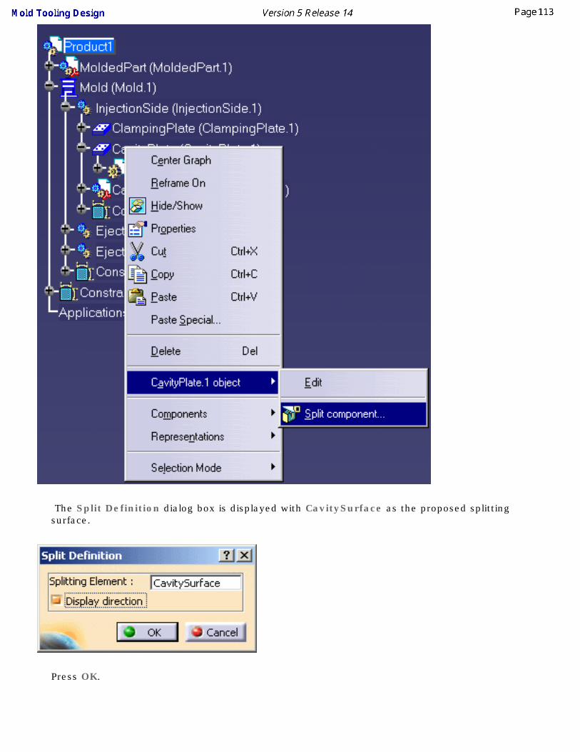
2. Open the contextual menu with the right mouse button and select the CavityPlate.1 object->
Split component command.

CavitySurface is given as the proposed splitting surface in this case because a surface with this name was found in the MoldedPart; if no surface with this name is found (No Selection) you will have to choose one from the MoldedPart.
Click on Display direction to show the direction in which the split will occur and then click on one of the the orange direction arrow on the mold to make sure the split will be upwards.
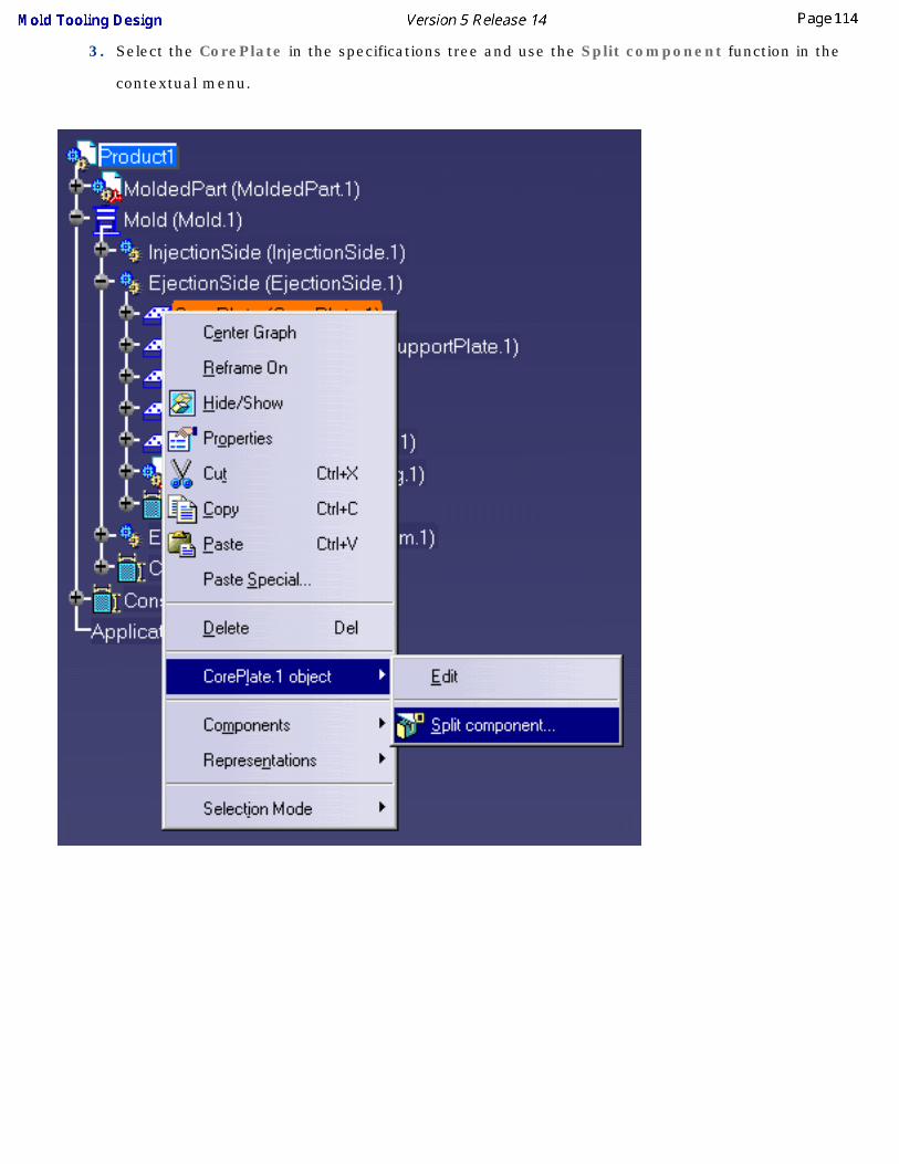
3. Proceed the same way with the core plate by selecting it from the Ejection Side in the
specification tree and applying a split action via the contextual menu.

No selection is given as the proposed splitting surface in this case because no CoreSurface was found in the MoldedPart. Select CoreSide in the PartingBody in the specifications tree.

Click on Display direction to show the direction in which the split will occur and then click on one of the the orange direction arrow on the mold to make sure the split will be downwards.

4. To obtain a better display of the completed split on the cavity and the core plates, hide the molded
part and the injection side display using the Hide/Show contextual command.
Here is what you should obtain:

Inserting Leader Pins in a Mold BaseThis task shows you how to insert mold components into a selected mold base.
In this exercise you will insert 4 leader pins that will be positioned on already existing points.
1. Click on the Add Leader Pin icon .
2. Use the browser to open the associated catalogs and select the Dme supplier:
Continue into detailed definition of the leader pin with the following selection:
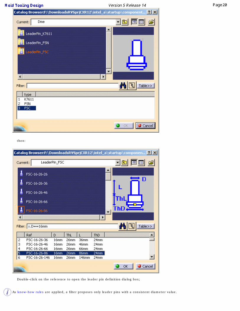
then:
Double-click on the reference to open the leader pin definition dialog box;
As know-how rules are applied, a filter proposes only leader pins with a consistent diameter value.

3. First select a point which is displayed as a filled circle (and not a cross) on the mold base.
As the point is called LeaderPini (i=1to 4), three other leader pins are automatically positioned on the other points named LeaderPini.
To create the holes associated to each leader pin, position the From and the To elements respectively to ClampingPlate and CavityPlate.
You obtain the following preview:
4. Click on OK to complete the creation of the leader pins.
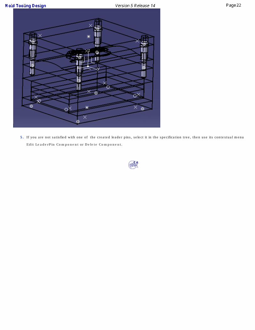
5. If you are not satisfied with one of the created leader pins, select it in the specification tree, then use its contextual menu
Edit LeaderPin Component or Delete Component.

Positioning Ejector Pins on a Mold BaseThis task shows you how to position mold components onto a selected mold base.
In this exercise you will create and position an ejector pin onto the current mold base.
1. Click on the Add Ejector Pin icon .
2. In the catalog browser dialog box, select the Hasco supplier and continue into more detailed definition of the ejector
pin as follows:
3. Double-click on the reference to display the ejector pin definition dialog box.
For an easier graphic selection of the EjectorPlateA bottom face, hide the display of the SettingPlate and EjectorPlateB.
As know-how rules are applied, a filter proposes only ejector pins with a consistent length value.

4. Pick the bottom face on EjectorPlateA as shown below:
5. Locate the ejector pin on the grid and define the plates to drill in the dialog box from EjectorPlateA to Core Plate.

6. Click on OK to validate the creation of the ejector pin. Here is the final result:

Creating a Gate
This task shows you how to create a gate on the molded part.
1. Put the Injection side into NoShow mode and ensure that the MoldedPart is in Show mode.
2. Click the Add Gate icon .
Enter On Curve as the Point type and select the PartingLine around the part in the viewer.
Click OK to confirm the location of the gate.
3. The gate definition dialog box is displayed.
Click on the catalog icon to open the catalog browser and double-click on Side type, then choose the Round type.
The following gate definition dialog box is displayed:
Keep the parameters:
● Side Round Type, stamped in the Core,
● with a length of 1.5 mm and a section of 0.5 mm radius.

Note that you can see the preview of the gate on the part if you zoom in.
4. Click OK to create the gate.
Note that a GateBody has been added to the MoldedPart in the specification tree.


Creating a Runner
This task shows you how to create a runner on the molded part.
1. Double click on MoldedPart in the specification tree.
2. Click the Sketcher icon and select the xy-plane in the specification tree.
3. Click the Project 3D Elements icon and select the gate that you just created (yellow
square). This projects the gate into the xy plane, i.e. the sketcher plane.
4. Sketch the runner path from the gate you have just created like this:

The runner path is made of lines and arcs, that should be continuous in tangency. This sketch will be the guide (Layout) along which a profile (Section) is swept to create the runner .
5. Exit the Sketcher with this icon and return to the product (double click on Product in the
specification tree).
6. Click the Add Runner icon .
7. The runner definition dialog box is displayed. Choose:
● to stamp the runner in the core and in the cavity,
● Round Type with a radius of 1,
● the sketch you just created as the Layout.
8. Click OK to create the runner.

Creating a Coolant Channel
This task shows you how to create a coolant channel.
1. Double click CoreCooling (in CoreCooling1).
2. Start the Wireframe and Surface Design application to create a point ( ) on the CoolingPlane. Do this by choosing On
Plane and clicking on yz1 in the specification tree (under Open body.1 or Geometrical set.1).
A small blue square is displayed that you can move around in the plane until you find a point that is satisfactory. Click to stop the square moving and press OK to confirm your selection.
3. Now create another point on the face on the opposite side of the CoreCooling. This ensures that the coolant channel will go
through the mold from one side to the other.
Double click on Product in the specification tree to go back to Mold Tooling Design.
4. Click the Add Coolant Channel icon and select the two points that you have just created.
5. The coolant channel definition dialog box and a cylindrical hole are displayed in the viewer.

6. Click OK to create the coolant channel.
Your specification tree should look like this:

Saving DataThis task shows you how to save your data once you have created your mold.
1. Create a directory where you want to store your data.
2. Use File > Save Management.
3. Choose the target directory and push the Propagate directory button. Click OK, the saving starts and all of the components that make up your mold are now
in the MyNewMold directory.

User Tasks
Preparing the Part to MoldCreating a Mold Base
Standard Mold ComponentsInjection features
HolesCatalogs
Generating the Bill of MaterialSaving Data
Using other Workbenches

Preparing the Part to Mold
This task shows you how to prepare the part before building the elements necessary to the mold.
1. Create a new CATPart with File > New and choose Part in the list. Using the contextual menu,
edit the part properties, go to the Product tab and give MoldedPart as its Part Number.
(You can also begin by creating a mold base which automatically contains an empty MoldedPart where you can complete the steps given below).
2. Open the Tel.CATPart file in the Samples directory. This opens a new viewer.
Select the PartBody in the specifications tree and copy it.
Select the Part in the MoldedPart viewer and use the Paste special function in the contextual menu.
Choose AsResultWithLink in the dialog box and click OK. This ensures that if the original part to mold is modified that the modifications will be applied to the MoldedPart.
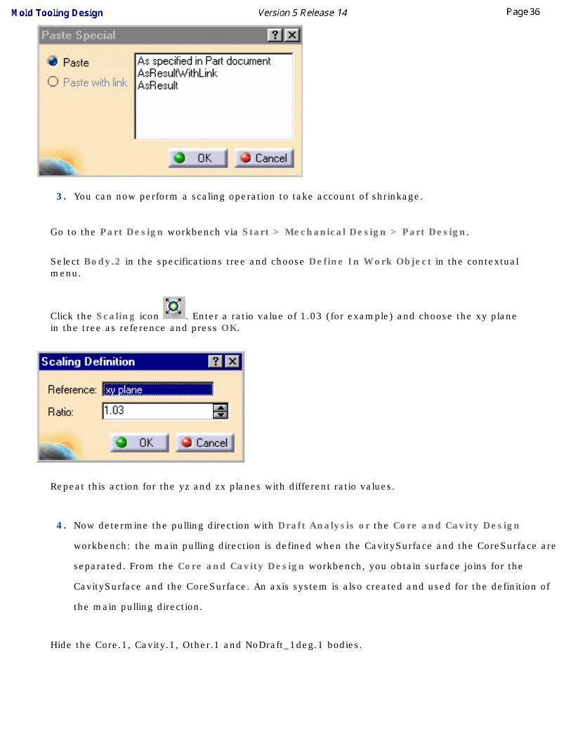
3. You can now perform a scaling operation to take account of shrinkage.
Go to the Part Design workbench via Start > Mechanical Design > Part Design.
Select Body.2 in the specifications tree and choose Define In Work Object in the contextual menu.
Click the Scaling icon . Enter a ratio value of 1.03 (for example) and choose the xy plane in the tree as reference and press OK.
Repeat this action for the yz and zx planes with different ratio values.
4. Now determine the pulling direction with Draft Analysis or the Core and Cavity Design
workbench: the main pulling direction is defined when the CavitySurface and the CoreSurface are
separated. From the Core and Cavity Design workbench, you obtain surface joins for the
CavitySurface and the CoreSurface. An axis system is also created and used for the definition of
the main pulling direction.
Hide the Core.1, Cavity.1, Other.1 and NoDraft_1deg.1 bodies.

5. Go to the Generative Shape Design workbench with Start > Shape > Generative Shape
Design.
Insert an Geometrical set and name it PartingBody.
6. Click the Join icon .
Select all of the bottom edges of the part.
Press OK in the dialog box to confirm the action.
Select the new join in the specifications tree.
Use the contextual menu to open its properties and call it PartingLine.
7. Now you are going to fill the hole on the part 9to enable the split of the CavityPlate and of the
CorePlate).
Do a Join operation on the curves around the hole and press OK in the dialog box.

8. Click the Fill icon .
Select Join.2 in the specifications tree. Press OK in the dialog box.
The hole is filled.
9. The next thing you are going to do is to create the parting surface.
● Select the Sweep icon .
● Choose the Line Profile type button in the dialog box.
● Choose With reference surface for the Subtype.
● Select PartingLine in the specification tree for the guide curve.
● Select xy plane in the specification for the Reference surface.
● Enter a value of 20 mm for Length 1.
● Click in the Angle box to activate the OK and Apply buttons.
● Press OK.

The parting surface is created (if it is created in the wrong direction, i.e. in the inside of the part, swap the values of Length 1 and Length 2).
Using the contextual menu, change the sweep name to PartingSurface.

10. Click the Extract icon .
Since the PartingSurface is shared by both the CavitySurface and the CoreSurface, it is generated on both.
Choose Tangent continuity for the Propagation type and click on any face on the upper surface in the viewer for the To Extract box.

Turn the part over and repeat this step for the underside surface.
11. Click the Join icon .
Choose PartingSurface, the fill and the first extract in the specification tree. Uncheck the Check connexity option.
Press OK.
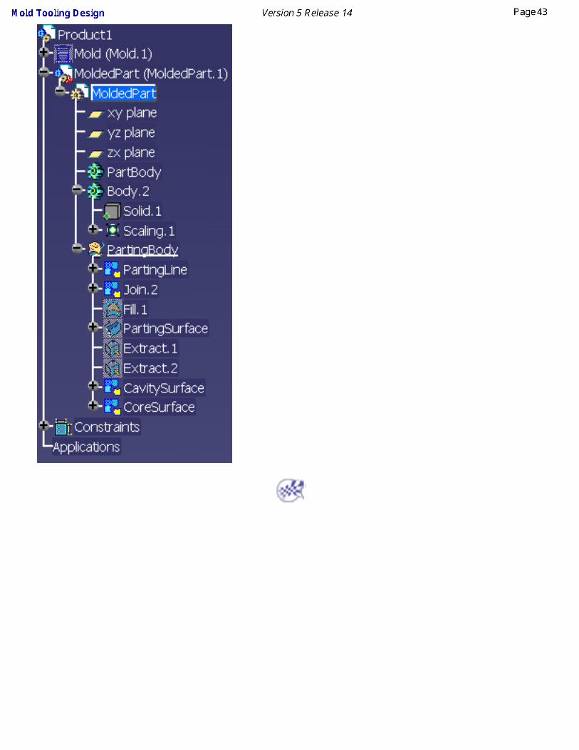
Select the new join in the tree. Using the contextual menu, choose Properties and change the name to CavitySurface.
Repeat the action with the parting surface, fill and the second extract. Call the new join CoreSurface.

Your specification tree should look like this:

Creating a Mold Base
Mold Tooling Design helps you create the set of plates that makes up mold bases.
You can also add new plates and inserts to an existing mold.
Creating a User-defined Mold Base Creating a Standard Mold Base
Adding a PlateAdding an Insert

Creating a User-defined Mold Base
This task shows you how to define the plates for your own mold base.
1. Click the Create a new mold icon .
2. By default, the following dialog box is displayed:
and the mold is pre-visualized :

This first panel is used to define a mold base.
● In the Plates column you can choose to include any proposed part in your mold base by checking or unchecking the corresponding plate. (by default, the Upper bar and the Stripper are not active, only the CavityPlate and the CorePlate are compulsory)
● You can enter the thickness of a plate using its spinner.
● In the Dimensions area, you can define the overall dimensions of the mold base as well as the overhangs for clamping and setting plates.
● You can also define the overlap value between the core, cavity and stripper plates.
● You can use the core support plate to simulate a sprue stripper plate.
● Define the upper bar width, riser width and ejector width with their spinners.
● Use the Enable in the Preview area to display the mold base or not.
Once you are satisfied with your settings, press OK to create the mold.

● InjectionSide, EjectionSide and EjectorSystem are defined as products for the MoldBase. This way, they can be edited separately.
● You can modify the formula that defines the default value by:
● double-clicking on Mold.1 to make it current.
● closing the dialog box
● then reopening it via the contextual menu (select Mold.1 in the specification tree then Mold.1 object > MoldEdition in the contextual menu),
● and pressing .
● You can also remove the formula by using Delete in its contextual menu.
Click on the icon to access the definition of standard mold bases. This button can only be used when creating a mold and not when editing it via :

Creating a Standard Mold Base
This task shows you how to create a mold base from a catalog.
Open the Snap.CATProduct from the Snap directory in the samples directory.
Recall the xy, yz and zx planes from the NoShow and compare this axis system with that of the main pulling direction of the part (in orange). You can see they are different.

1. Click on the Create a new mold icon . The Create a new mold dialog box is displayed, ad the mold is pre-visualized around the molded part.
Note that the pre-visualization is done into the molded part position and orientation.

3. In the New Mold dialog box, click on the catalog icon to access the catalog browser. The mold pre-visualization is erased and the catalog browser is displayed.
4. Double-click on the name of the supplier you want to select (Dme, Eoc, Hasco, etc.) to visualize a pre-display of the mold base in the top right window.

Note that a rectangle is displayed in the viewer showing you the width and the length of the reference you have selected.

5. Double-click on a reference to revert to the first panel of the dialog box to customize it, if necessary.

6. Click OK to create the mold. The molded part has been snapped in the right orientation and located in a middle position between cavity and core plates.
● By default, the mold is created in the axis system of the main pulling direction. You could have picked another axis system to orient the molded part.
● The InjectionSide, the EjectionSide and the EjectorSystem are now created as CATProducts. This way, they can be edited separately.

Adding a Plate to a Mold
This task shows you how to add a plate to a mold.
1. Open AddPlate.CATProduct in the samples/AddPlate directory.
2. Click the Add Mold Plate icon .
3. In the dialog box, choose UpperBar for the Configuration Type.
Note that the only types of plates that you can choose are those that are not already included in
the current mold.
The Positioning tab gives you information on the location of the plate you have selected:
● its position (origin X,Y,Z)
● its position with respect of the plate above or below
● its position in the mold (InjectionSide, EjectionSide, EjectorSystem).
You cannot modify any of these parameters.

The Parameters tab allows you to change the thickness, width and length values. You can also extend the width and length of some plates (usually ClampingPlate and SettingPlate) beyond the mold itself.
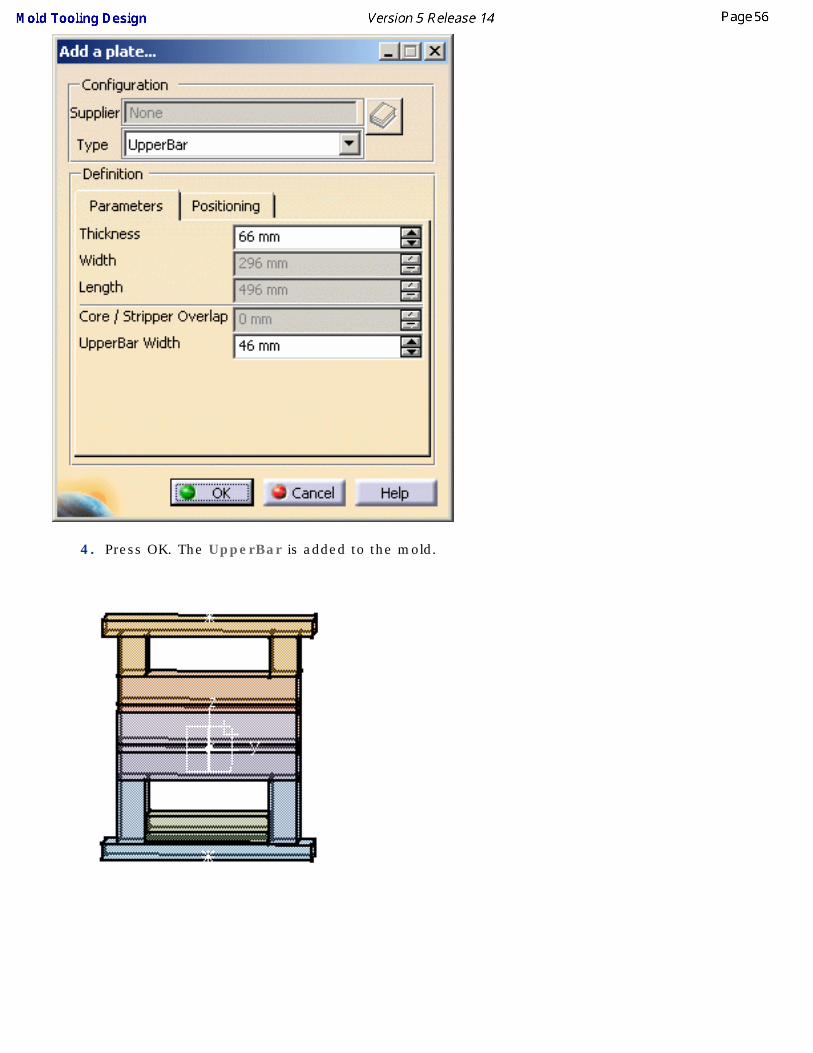
4. Press OK. The UpperBar is added to the mold.

All plates have a specific position in the mold. These positions cannot be changed.

Adding an Insert to a MoldThis task shows you how to add an insert in a mold.
An insert is a particular type of component that has core/cavity properties, i.e. it can be pierced by coolant channels and can be attached by other components.
An insert may be placed either on the CavityPlate or the CorePlate.
1. Open AddInsert.CATProduct.
Select InjectionSide in the specifications tree and hide it (Hide/Show in the contextual menu.

2. Click the Add Insert icon .
When the dialog box is displayed, press the catalog button and choose Pad with Chamfer and then Pad by double clicking both times. Then slightly pivot the mold so that you can see the underside of the CoreSupportPlate. Click this surface.
3. Click a little to the left of the center of the surface to locate the pad.
4. In the dialog box, enter a value of 36 for Z and Drill from the CorePlate.
The parameters tab lets you modify the height, width and length of the pad and also the draft angle and chamfer size. For this exercise we are going to leave them unchanged.
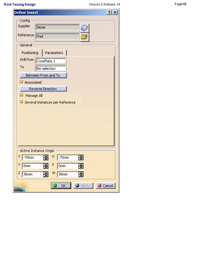

5. Press OK. The insert is created.

Standard Mold Components In this section you will find the detailed description of all the standard mold components with the associated procedures for positioning them in, or deleting them from, the mold base.
The components are grouped together according to their types:
Mold base componentsGuiding componentsLocating componentsFixing components
Ejection componentsInjection components
Miscellaneous components
Those are the chapters on editing standard components:
Component ParametersAdding Components
Contextual Menu of ComponentsUser Component Requirements
Positioning a SliderReplacing Components
Copying a Component ReferenceSplitting Components
Adding or Removing Material around a Component

Components and their ParametersThis section explains the parameters for each component type. The yellow square in each of the images indicates the origin of the component axis system and facilitates positioning.
Mold base components
Mold Base Parameters defined at Mold Product level:
● MoldL - Main length of the mold
● MoldW - Main width of the mold
● OverL - Length overhang for clamping and setting plates
● OverW - Width overhang for clamping and setting plates
● UppW - Width of upper bars
● RisW - Width of riser bars
● EjeW - Width of ejector plates
● CorCavS - Overlap between cavity and core plates. Default value=0.8xheight of core plate
● StripOverlap - Overlap between stripper and core plates
● SPShH - Distance between setting and ejector plates (it corresponds generally to the height of the shoulder of the stop pins)
Parameters defined for each plate:
● H - Height of the plate

Slider● L - Slider support length
● W - Slider support width
● H - Slider support height
● WT - Slider guide rail width
● HT - Slider guide rail height
● LP - Slider shelf length
● HP - Slider shelf height
● AP - Slider shelf angle
● LF - Slider form length
● HF - Slider form height
● WF - Slider form width
● HD - Height that the slider form is raised
● Draft - Slider form draft angle on the vertical faces
● DraftB _ Slider form draft angle on the bottom face
● DepthPocket _ Slider pocket depth
● AnglePinPos - Angle pin positioning angle
● Retraction - Slider retraction
● AnglePinD - Angle pin hole diameter
Retainer● L - Guide rail length
● W - Width between the guide rails
● WT - Retainer width
● HT - Retainer height
● WR - Guide rail width
● HR - Guide rail height
● DepthPocket - Guide rail pocket depth
If you select a slider that corresponds to a retainer (while the retainer creation dialog box is open) the retainer parameters are automatically adapted to match those of the slider.
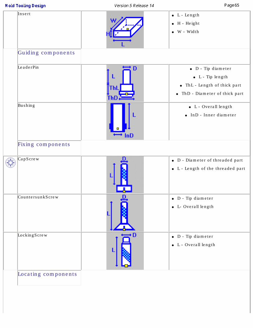
Insert● L - Length
● H - Height
● W - Width
Guiding components
LeaderPin● D - Tip diameter
● L - Tip length
● ThL - Length of thick part
● ThD - Diameter of thick part
Bushing● L - Overall length
● InD - Inner diameter
Fixing components
CapScrew● D - Diameter of threaded part
● L - Length of the threaded part
CountersunkScrew
● D - Tip diameter
● L- Overall length
LockingScrew● D - Tip diameter
● L - Overall length
Locating components

Sleeve● L - Overall length
● InD - Inner diameter
LocatingRing● ShD - Shoulder-to-shoulder
diameter
● L - Overall length
● D - Insertion diameter
DowelPin● D - Diameter
● L - Overall length
Ejection components
EjectorPin● D - Tip diameter
● ThL - Length of the thick part of the pin
● L - Overall length
Ejector● D - Tip diameter
● L - Overall length
FlatEjector● H - Width of flat area
● G - Length of flat area
● L - Overall length
EjectorSleeve● InD - Inner diameter
● L - Overall length

CorePin● D - Tip diameter
● L - Overall length
StopPin● ShH - Shoulder height
● ShD - Shoulder diameter
AnglePin● D - Diameter
● L - Overall length
KnockOut● D - Diameter
● L - Length
Injection components
SprueBushing● RunD - Runner diameter
● L - Injection length
● ShD - Shoulder diameter
SpruePuller● RunD - Runner diameter
● L - Overall length
SupportPillar● L - Length
● D - Diameter

O-Ring● D1 - Inner diameter
● D2 - Cross section diameter
Plug● D - Diameter
● L - Length
Baffle● W - Width
● L - Length
● T - Thickness
● D - Diameter
Miscellaneous components
User Component● There are no fixed parameters
for this component because they depend on the type of component in the catalogue.
EyeBolt● D - Diameter of threaded part
Spring● Di - Inner diameter
● Do - Outer diameter
● Lo - Overall length

Adding Components This task shows you how to select and position standard components.
The dialog box and the operating mode are the same for all components.
Components can be added to an existing mold or to an empty CATProduct
Adding a component to an existing moldCreate a mold as explained in Creating a User-defined Mold Base.
You will:● choose a first reference, (go directly to Positioning a component if a reference is already in use)
● position the component,
● create and manage several instances,
● drill holes,
● set the parameters values,
● activate a rule,
● Creating a Component in an Empty CATProduct.
Choosing a first reference
1. Click on one of the component icons (here Add LeaderPin). The Define LeaderPin dialog box is displayed.

2. Press the catalog icon to access the catalog browser. Select the catalog name, then the component type and the
component reference: double-click on the required label to go to the next step, the last one reverting to the main dialog box,
with its Config fields updated with the Supplier name and the Reference of the component.

The Config area is a reminder of the reference of the component. It can not be edited. You can only select another reference of a
component of the same type, using the catalog icon , or select another reference from a file, using the File Open icon .
You could use one of your own components instead of one from a catalog:
Press the File Open icon in the dialog box and browse your directories to that containing your component. Select the component. You are then asked to position it, as in step 3 below. The Config fields are not updated.
Special case of the screws (CapScrew, CountersunkScrew, LockingScrew)
The operating mode is the same, but is enhanced by a smart filter in the catalog.
If the Drill to field is already defined, the distance between the active preview location and the To plate is computed, i.e. a minimum and a maximum lengths are computed for the screw.
These minimum and maximum lengths are set as filters for the Catalog browser dialog box, applied to the L parameter of the screw,

so that only references with consistent lengths are proposed.

(we have resized the dialog box to display all proposed references)You can further refine the selection filter by using the Specifics tab :
● Sunk Head is active by default and you can enter the value that you want the head to be sunk into the plate by (0mm means that the head is flush with the plate surface),
● Check Diameter to select a diameter for the screw (to refine selection filtering),❍ The first value is the diameter of the screw,
❍ The second value is the coefficient that defines the distance to which the tip of the screw will be sunk into the To plate (drilling destination plate).
If, for instance, we wanted to drill from clamping plate to cavity plate, we might obtain the following selection to choose from:

but if we added that we wanted a screw with a diameter of 10mm, the selection to choose from would be much shorter:
If the Drill to field is not defined, or if you clear the filter field,
you can then select any screw from the complete list.

● The distance is computed from the component location, the filter is then computed for an outer head screw or inner head screw.
● The location taken into account is the active preview location. If you activate another preview location, the filter will be updated.
● The screw axis is taken into account.

Positioning the component
● Standard components are "smart" - they know where they should be in the specification tree when they are created. In some cases (e.g. angle pin, insert, fixing components, guiding components, locating components and spring), it is not automatic, the position of the components is determined by the information you give in the Drill from field. This allows the positioning constraint between the component and any plate.
● In the Tools, Options menu, then Mechanical Design, Mold Tooling Design customization dialog box, you can define a default plate positioning for the components. That way, when you create a new component of a customized type, it will be positioned automatically on the correct face of the correct plate, without previous picking.
● In the Tools/Options/Mechanical Design/Sketcher, activate the Position sketch plane parallel to screen option, or the Grid Snap to Point option if needed.
3. Select a face of a plate. The sketcher is displayed, with a manipulator to position the component. The Drill from field is
updated automatically with the name of the plate you have selected.
The grid is displayed. The Active Instance Origin is updated. You can now define the coordinates of the new components by picking either:
● a 2D point on the face,
● a 2D point outside the face that will automatically be projected onto the face,
● a 2D point sketch on the face,
● a 2D point sketch outside the face that will automatically be projected onto the face,
● a 3D point on the face,
● a 3D point outside the face that will automatically be projected onto the face, or
● an axis, an edge, or a line that will automatically intersect with the selected face.
You can easily line up a new component with an existing one by picking the axis of the existing component when creating the new one.
You may then modify the coordinates values:
● by hand, if desired, using either the X, Y, Z coordinates or the U, V, W local coordinates.
● by using the arrows to move the component on the plane.
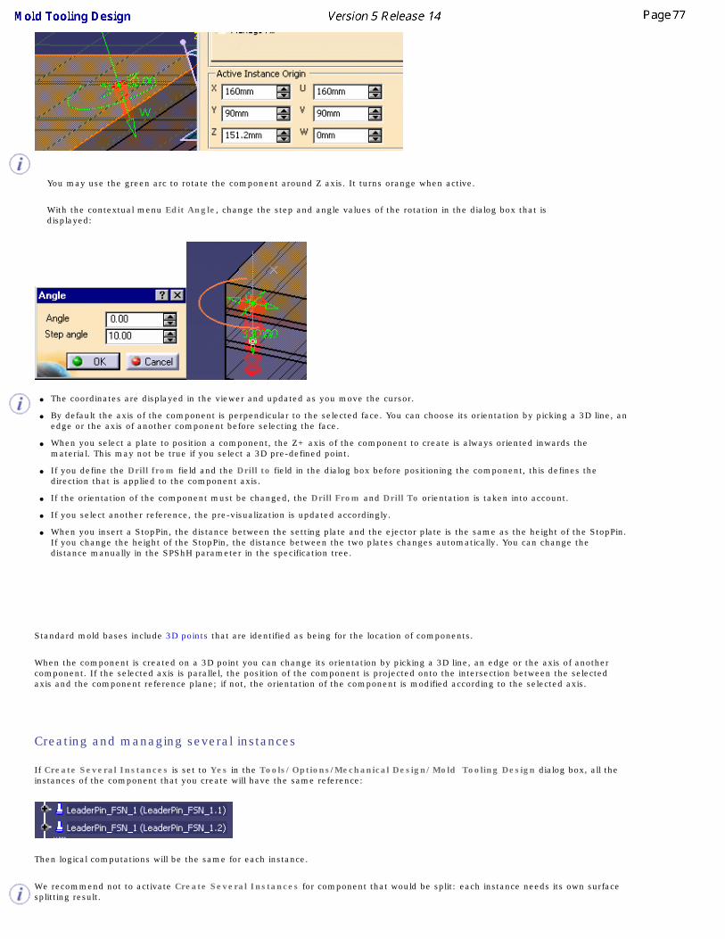
You may use the green arc to rotate the component around Z axis. It turns orange when active.
With the contextual menu Edit Angle, change the step and angle values of the rotation in the dialog box that is displayed:
● The coordinates are displayed in the viewer and updated as you move the cursor.
● By default the axis of the component is perpendicular to the selected face. You can choose its orientation by picking a 3D line, an edge or the axis of another component before selecting the face.
● When you select a plate to position a component, the Z+ axis of the component to create is always oriented inwards the material. This may not be true if you select a 3D pre-defined point.
● If you define the Drill from field and the Drill to field in the dialog box before positioning the component, this defines the direction that is applied to the component axis.
● If the orientation of the component must be changed, the Drill From and Drill To orientation is taken into account.
● If you select another reference, the pre-visualization is updated accordingly.
● When you insert a StopPin, the distance between the setting plate and the ejector plate is the same as the height of the StopPin. If you change the height of the StopPin, the distance between the two plates changes automatically. You can change the distance manually in the SPShH parameter in the specification tree.
Standard mold bases include 3D points that are identified as being for the location of components.
When the component is created on a 3D point you can change its orientation by picking a 3D line, an edge or the axis of another component. If the selected axis is parallel, the position of the component is projected onto the intersection between the selected axis and the component reference plane; if not, the orientation of the component is modified according to the selected axis.
Creating and managing several instances
If Create Several Instances is set to Yes in the Tools/Options/Mechanical Design/Mold Tooling Design dialog box, all the instances of the component that you create will have the same reference:
Then logical computations will be the same for each instance.
We recommend not to activate Create Several Instances for component that would be split: each instance needs its own surface splitting result.

If this option is set to No, each instance of the component that you create will have its own reference:
The Manage All option defines whether you create just one instance of the component or several in one shot depending on what you select to position the component. When this option is active:
● selecting a 2D point will effectively select all of the other 2D points in the mold and create an instance of the component on each of them,
● selecting a 3D point will select all of the 3D points on the same face.
● the previews of all instances of the component are active (red) meaning that moving one component preview (or reversing its direction) will move all the other instances of the component (or reverse their direction).
Please note that Reverse Direction and rotation angle values are always applied to everything that is selected whether Manage All is active or not.
Ex: select LeaderPin4 with Manage All de-activated. Only one instance is created.
Ex: select LeaderPin4 with Manage All active. The four instances are created.

● Once several instances of a component have been created, Manage All defines whether your modifications apply to all or only one instance.
Ex: The four instances were created with Manage All active. It was then de-activated. Only the instance created on the point picked remains active.
● The active component is always red, the others are green.
Several Instances per Reference allows you to create several instances of one reference component. If you deactivate this option, only one instance will be created per reference component.
This option overrides the same setting in Tools/Option and is only applied to the current creation.
Drilling holes and positioning

● For all components but screws, open holes are drilled.
When dealing with screws, the type of hole depends on your selection for the Drill from and Drill to locations:
❍ if only the Drill from location is defined, either as a plate or a component, a standard hole is drilled,
❍ if only the Drill to location is defined, either as a plate or a component, a tapped blind hole is drilled,
❍ if both areas are defined, either as a plate or a component for each one, the hole is standard in the element set as the Drill from location and a tapped blind hole in the element set as the Drill to location.
Except when you are working on a support, by default, the Drill from and Drill to area are set to No selection (no hole drilled). If
you wish to define the holes associated to the component, first select the fields Drill from or Drill to in the dialog box, then pick a
plate or a component in the graphic area to define the other reference plate.
● If you wish you can select the plate or component in the specification tree (expand the tree first and select the reference).
● When working with a support, selecting the plate updates automatically the Drill from field with the name of that plate.
● All plates located between the two reference plates are drilled as well.
● For all pads and pockets created by Adding or Removing Material: pockets are removed whereas pads are added in the Drill from (plate or component) area.
The Between From and To button has become available.
You can now select plates or other components found between the Drill from element and the To element:
● select an element in the viewer to add it to the list of elements to be drilled,
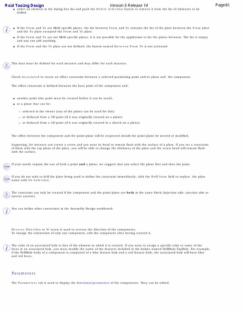
● select an element in the dialog box list and push the Delete Selection button to remove it from the list of elements to be drilled.
● If the From and To are Mold specific plates, the list between From and To contains the list of the plate between the From plate and the To plate excepted the From and To plate.
● If the From and To are not Mold specific plates, it is not possible for the application to list the plates between. The list is empty and you can add anything
● If the From and the To plate are not defined, the button named Between From To is not activated.
This data must be defined for each instance and may differ for each instance.
Check Associated to create an offset constraint between a selected positioning point and/or plane and the component.
The offset constraint is defined between the base point of the component and:
● another point (the point must be created before it can be used),
● or a plane that can be:
❍ selected in the viewer (any of the plates can be used for this)
❍ or deduced from a 3D point (if it was originally created on a plane)
❍ or deduced from a 2D point (if it was originally created in a sketch on a plane).
The offset between the component and the point/plane will be respected should the point/plane be moved or modified.
Supposing, for instance you create a screw and you want its head to remain flush with the surface of a plate. If you set a constraint of 0mm with the top plane of the plate, you will be able to change the thickness of the plate and the screw head will remain flush with the surface.
If your needs require the use of both a point and a plane, we suggest that you select the plane first and then the point.
If you do not wish to drill the plate being used to define the constraint immediately, click the Drill from field to replace the plate name with No Selection.
The constraint can only be created if the component and the point/plane are both in the same block (injection side, ejection side or ejector system).
You can define other constraints in the Assembly Design workbench.
Reverse Direction or W arrow is used to reverse the direction of the components. To change the orientation of only one component, edit the component after having created it.
The color of an associated hole is that of the element in which it is created. If you want to assign a specific color to some of the faces in an associated hole, you must modify the name of the features included in the bodies named DrillHole/TapHole. For example, if the DrillHole body of a component is composed of a blue feature hole and a red feature hole, the associated hole will have blue and red faces.
Parameters
The Parameters tab is used to display the functional parameters of the components. They can be edited.

Example - Editing the Parameters for Fixing components
Those are the CapScrew, CountersunkScrew, LockingScrew.
You may need to edit their DrillHoleLength parameter. This parameter manages the height of the hole from the head of the screw. You may need to edit it because too long a hole has been created:
First, make sure the following options are checked :
Parameters in Part Infrastructure/Display tab
With value and With formula in the Parameters and Measure/Knowledge tab

so that the Parameters section of the CapScrew is displayed in the specification tree
You will note that only three parameters are available in this section, as in the CapScrew edition dialog box.
Now, right-click on Parameters to launch its contextual menu and select Hidden Parameters...
In the list that is displayed, select DrillHoleLength and click Show.
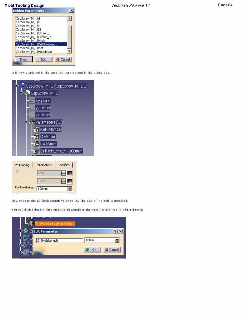
It is now displayed in the specification tree and in the dialog box.
Now change the DrillHoleLength value to 16. The size of the hole is modified.
You could also double-click on DrillHoleLength in the specification tree to edit it directly.

Activate Rule
You can use an knowledgeware rule. This rule is stored in the rules catalog. It can be used to modify the geometry of a component, or to check its validity, ...
1. Click on the catalog icon and select a rule.
2. The name of the rule is displayed in the field to the left of the icon.
3. According to your needs, check the Activate Rule option to activate it as it is imported in the component.
Creating a Component in an Empty CATProduct
This task shows you how to create components in an empty CATProduct, to create assembled components for example.
1. Select File/New and choose Product in the New dialog box.
2. Click the icon Add Insert . The Insert dialog box is displayed.
3. Select the required Insert from the catalog As shown above.
4. Click in the viewer where you want to place the origin of the instance. The origin will be located on the view plane on the
mouse pick, with an axis corresponding to the main OZ axis. The spinners are updated with the coordinates values while you
move the component with manipulators so that you can position it precisely.
5. Press OK to create the insert.

Contextual Menu of Components
This task shows you how to use the contextual menu of components:
1. Open file MoldWithMoldedPartAndComponents.CATPoduct in the samples/MoldAndPart directory.
2. Choose LeaderPin_FSN_1.1 in the specification tree or in the viewer (this is an example, the labels will vary with the name of the
component). Use LeaderPin_FSN_1.1 object contextual menu.
Edit
This item does not apply to Mold Tooling Design
Open in New Window
This open the CATPart of the component in a new window, where you can edit it.
For example, we have changed the shaft angle of the LeaderPin in the new window, this change is taken into account in all the instances of the LeaderPin in the Product.

Edit LeaderPin Component
The component edition dialog box is displayed.
You can now modify the positioning of the component, its origin, its direction, the Drill from/To positioning and its parameters.Try pushing the Reverse Direction button or changing the Origin X. You will see a preview of the result.Try picking the W green arrow on the graphic display to reverse the orientation or picking another point or face to change the position of the component. You will see a preview of the result.

Note that the coordinates are displayed under the cursor as you move it.
You can also modify the component parameters in the Parameters tab. This tab is similar to that of the Define dialog box.
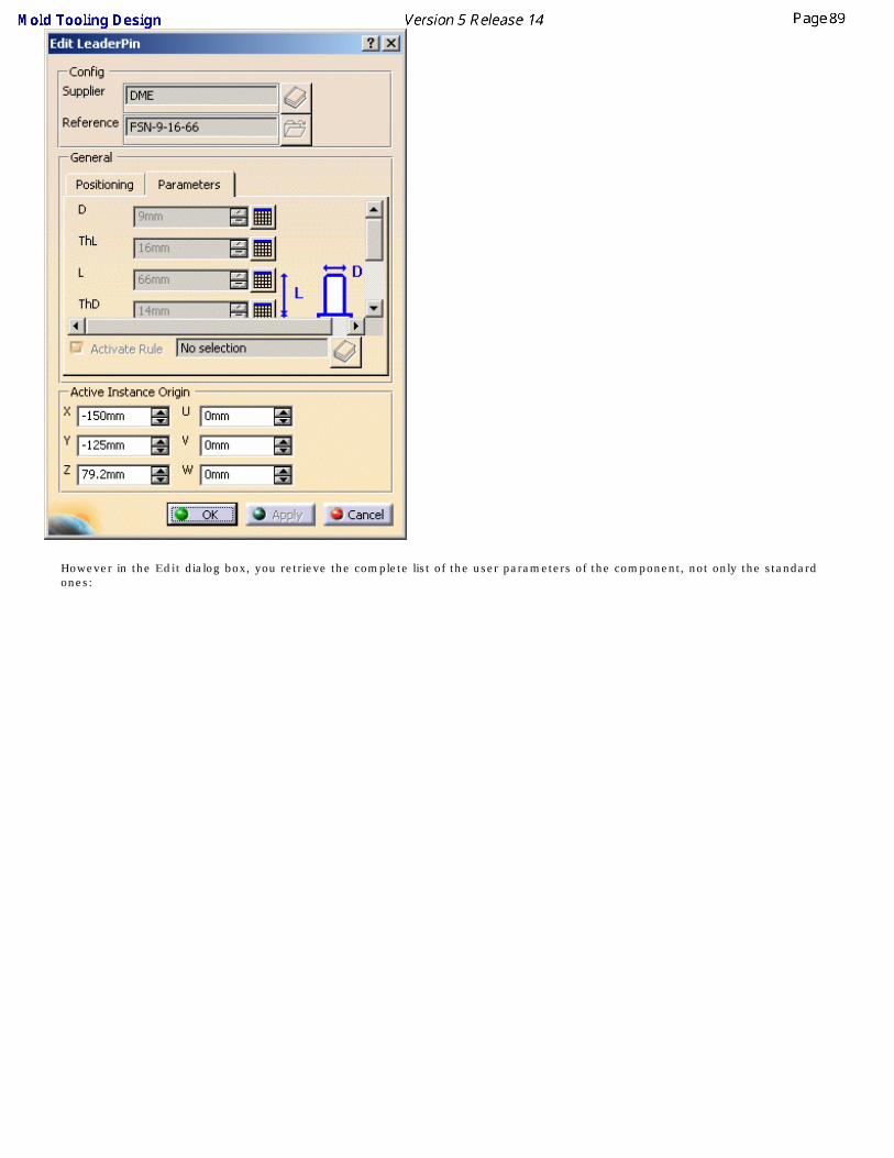
However in the Edit dialog box, you retrieve the complete list of the user parameters of the component, not only the standard ones:

This is particularly useful to edit user components.
Use the slider of the tab to browse all the data available.
4. Press OK to apply your modifications.
When editing components, you cannot modify the original supplier but you can change the reference in order to change the dimensions.
Delete component
Deletes the components and their associated holes.
We recommend that you do not use the ordinary Delete function, since the associated holes would not be deleted.
Add New Instance
Enables you to add new instances of a given reference. The operating mode is the same as in Adding Components, with the difference that you are not allowed to change the supplier references.

User Component RequirementsThis task explains the requirements for a user component. A user component is a component that does not belong to a supplier catalog. These components must be added to a user's catalog.
The examples below are taken from WearPlate.CATPart which as been added to MyComponents.catalog found in the catalog directory in the samples directory.
Structure of a component
To obtain a good result when inserting user components in a Mold Tooling Design project, it is important to follow some rules detailed hereafter.
A Mold Tooling Design component can be a CATPart or a CATProduct, which may contain one or several CATPart that can be Mold Tooling Design components.
The name of the CATPart or of the CATProduct must be the name of the user component that is also used in the catalog (here WearPlate_Z15W).
A CATPart of a component is composed of:
Parameters● We recommend to orient the Z+ axis of the component upwards (towards the injection side).
● Some parameters that can be associated to one or several design tables. This is recommended if an object has several sets of parameters. The names of the design tables are free.

● Some of these parameters (e.g. B, S and L in the image below) need to be accessed during the insertion/edition of the component: they are displayed in the parameters tab of component panel.

To allow this display, the name of the concerning parameters must be put as keywords in the corresponding catalog (B, S and L in the image below).
● Only one parameter named Ref (string) that represents the supplier reference is mandatory. Its contents is displayed in the Config/Reference field of the dialog box used to add or edit a component

● and copied to the Nomenclature field of the Product properties (useful for the Bill of Material) of the inserted user component.
● The names of the other parameters are free.
● For the Bill of Material, it is also recommended to add some properties such as Material and Heat Treat in the Product properties of the CATPart of the

component, using the Define other properties... button. Standard components from Mold Tooling Design already contain the added properties Material and HeatTreat.

Bodies
● The PartBody that contains the geometry of the component. It may consist of pads, sketches, etc. The name of the PartBody is free.
● A body named BaseBody that contains a point named Base to locate the component when it is inserted in the mold. In case of assembled component (a CATProduct), the Base point of the first CATPart is taken into account for the location.
● If needed, a body with a name that starts with DrillHole that contains the definition of the associated drilled holes that are removed in the elements defined through the Drill From/To function of the component panel. There may be several of these and we recommend that you insert as many as necessary for your machining strategy (to differentiate, for instance, the holes that were in the original part to machine and the holes that you wish to insert.
● If needed, a body with a name that starts with TapHole that contains the definition of the associated threaded holes that are removed in the element defined through the Drill To function of the component panel (this element is the latest of the list).

● Pads can be used to add material around a component. Give the body a name that begins with Pad , e.g.PadForContouring. We recommend that you choose names that indicate the final purpose of the pad or pocket as there may be several in a user component.
● Pockets can be used to remove material around a component. Give the body a name that begins with Pocket e.g.PocketForMilling. We recommend that you choose names that indicate the final purpose of the pad or pocket as there may be several in a user component.
Pads and pockets are only applied to the element defined in the DrillFrom field of the Define Component dialog box.
The Explode Holes command takes into account only Hole features defined in the bodies DrillHole, TapHole or CoolingBody. Other types of features are ignored. Therefore, pockets, grooves, patterns, symmetries, translations, rotations, thicknesses,... that might be defined in those bodies are not processed by the Explode Holes command and you should not define components with those features.
For more information, see the Explode Holes User Task.

Positioning a Slider
This task teaches you how to position a slider with respect to the z axis in a slider axis system defined in Core and Cavity Design.
You will need a mold base with a molded part.
1. Open file MoldProduct.CATProduct in the samples/PositionSlider directory.
2. Expand the tree and hide the injection side of the mold.
3. Create a slider.
Position the slider on the appropriate plate (usually the CorePlate, or eventually the CavityPlate) in your mold base and use the arrows to set it in place.

Note that the coordinates are displayed under the cursor as you move it.
4. Align it with the slider Z axis either by selecting it on the model or by clicking on it in the tree
(Slider Direction.1).
5. Make any other adjustments you may wish and press OK.

Rounding up of (AP angle)
When you insert a slider, you can manage the associated Angle Pin angle by defining the parameter named Retraction in the panel of this type of component.
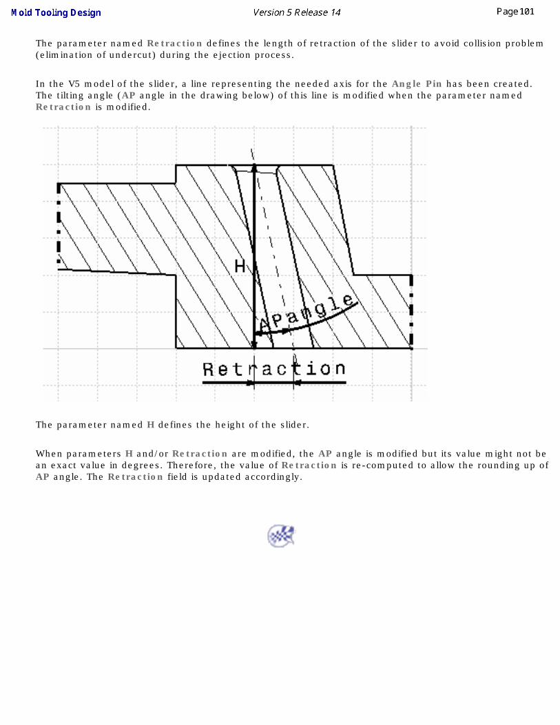
The parameter named Retraction defines the length of retraction of the slider to avoid collision problem (elimination of undercut) during the ejection process.
In the V5 model of the slider, a line representing the needed axis for the Angle Pin has been created. The tilting angle (AP angle in the drawing below) of this line is modified when the parameter named Retraction is modified.
The parameter named H defines the height of the slider.
When parameters H and/or Retraction are modified, the AP angle is modified but its value might not be an exact value in degrees. Therefore, the value of Retraction is re-computed to allow the rounding up of AP angle. The Retraction field is updated accordingly.

Replacing ComponentsThis task will show you how to replace a component by another from the same reference catalog.
You need at least one component to replace (the first two steps below deal with that).
1. Open file Product1.CATProduct in the DrillFrom\samples directory, show the injection side and hide
the ejection side and the ejector system.
2. Create three sleeves ( ) from the DME catalog, reference TD-28-120 anywhere on the
clamping plane.


3. Select Sleeve_TD_1.2

4. Use the contextual menu to choose the Replace Component option (you can also access it via Edit
in the menu bar).

5. Choose TD-50-180 to replace it via the catalog button in the dialog box that is displayed and press
OK.

6. Note that the sleeve reference in the tree has changed and the dimensions of the sleeve in the
viewer now correspond to its new reference.
You can only replace reference with another reference from the same catalog.
We suggest you go directly to the chapter on copying a reference.

Copying a Component ReferenceThis task shows you how to replace a component reference by another, from another catalog, if required.
You need at least one component to replace.
1. Open file Product1.CATProduct in the DrillFrom\samples directory, show the injection side and hide the
ejection side and the ejector system.
2. Create three sleeves ( ) from the DME catalog, reference TD-28-120 anywhere on the clamping
plane.

3. Select Sleeve_TD_1.1

4. Use the contextual menu to choose the Replace Component option (you can also access it via Edit in
the menu bar).

5. Choose Z20/54x280 from Hasco to replace it via the catalog button in the dialog box that is displayed
and press OK.
Note that the sleeve reference in the tree has changed and the dimensions of the sleeve in the viewer now correspond to its new reference.

Splitting Components
This task shows you how to split the cavity plate and the core plate with a surface.
Sprue bushing and other user components can also be split. A splitting surface may be the core, cavity or any other appropriate surface.
When splitting a component, all bodies included in the component will be split. If there is a body that you do not want to split, rename it with two underscores as a prefix (i.e. body1 becomes __body1).
When the number of instances of the component is greater than 1, a dialog box informs you that the component cannot be split.If you wish to have only one instance per reference, deactivate the Many instances by reference option in Tools > Options > Mold Tooling Design > Component.When ejectors, ejector pins, ejector flats, ejector sleeves and core pins go through a component that is split, their guided hole length will be maintained even though their overall length is shortened. Guided hole length is defined by the Offset Parting parameter.
1. Open Split.CATProduct in the samples/Split directory.
2. Select CavityPlate in the specifications tree and use the Split Component function in the
contextual menu.
The Split Definition dialog box is displayed with CavitySurface as the proposed splitting surface.
Press OK.
3. Select the CorePlate in the specifications tree and use the Split component function in the
contextual menu.

The Split Definition dialog is displayed with No selection (because no Core surface was found in the MoldedPart).
Expand the specifications tree and select CoreSide in the MoldedPart. Press OK


Here is the result:
The part of the component that is kept after the split operation depends on the mold and the component.
Select the Display direction option in the Split Definition dialog box to display arrows indicating which side of the component is to be kept.

Adding or Removing Material around a Component
This task shows you how to add or remove material around a component by adding bodies. We are going to use a ready prepared component that will illustrate both addition and removal and we shall add it to the clamping plate.First you must have created bodies with Part Design. If you wish to add material around a component, give the body a name that begins with Pad , e.g.PadForContouring. If you wish to remove material around a component, give the body a name that begins with Pocket e.g.PocketForMilling.
We recommend that you choose names that indicate the final purpose of the pad or pocket as there may be several in a user component.
Pads and pockets are only applied to the element defined in the DrillFrom field of the Define Component dialog box.
These bodies will be used in the order they were created.
1. Open AddInsert.CATProduct in the samples/AddInsert directory.
Expand the tree to show the contents of the clamping plate.

2. Click the Add a user component icon and browse to select
WearPlate_Z15W_1_1.CATPart in the samples/AddRemoveMaterial directory.
3. Position it on the top face of the clamping plate and Drill from ClampingPlate.1.


4. Press OK.
The violet area is the pocket where material was removed.
The green area is the pad where material was added.
Note that a Pad and a Pocket have been added to the ClampingPlate in the tree.

Modifying the Geometry of ComponentsThe geometry of components can be modified by:
● using the Part Design application to do so,
● using the design tables (see Using Knowledgeware Capabilities in CATIA Infrastructure User Guide)
● opening the component in a new window.

Injection Features
There are three types of injection features:
Modifying the Geometry of ComponentsGates
RunnersCoolant Channels

Gates
This task shows you how to create and edit gates along a parting line on the mold base.
1. Open file MoldWithMoldedPartAndComponents.CATPoduct in the sample/MoldAndPart directory.
You can create one or several gates, either:
● on the parting line (recommended), or
● directly on the molded part (using existing 3D points or vertices, ...).
2. We are going to create one gate. Select Mold1 in the specification tree and use the Hide/Show
function in its contextual menu to hide it (this is not obligatory but makes it easier to demonstrate
point selection).
Click on the Add Gate icon.
The point definition dialog box is displayed.
3. Select a point on the molded part to define the position of the gate.

Press OK.
4. A GateBody and a Gate.1.1 point are created in the specification tree and the gate definition
dialog box is displayed.

5. Stamp is used to create the gate either in the cavity and/or in the core.
6. Location: Push the point icon to modify the position of the gate.
7. Click on the catalog browser icon to define the type of the gate: Side, Direct or Submarine.
The following panel is displayed:

You can use your own catalog if you choose. Press on this icon in the dialog box and browse to the location of the catalog of your choice.
8. Double click on the Type to select the section shape: Round, Rectangular, Conic or
Cylindrical. Then adjust the parameter values accordingly. The type of section you can use
depends on the type of gate you choose.
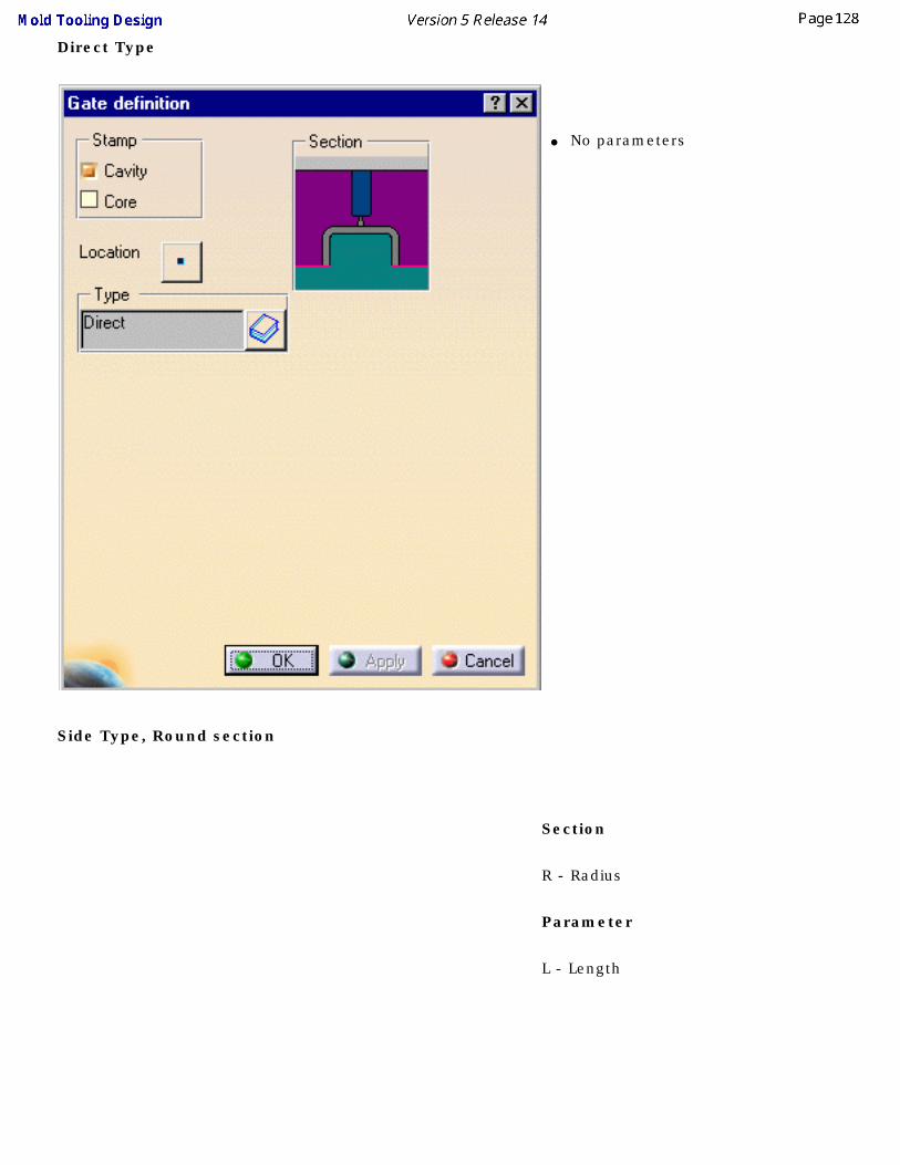
Direct Type
● No parameters
Side Type, Round section
Section
R - Radius
Parameter
L - Length

Side Type, Rectangular Section
Section
● H - Height
● W - Width
Parameters
● L - Length

Submarine Type, Cylindrical Section Section● A - Aperture angle
● H -Height
● L1 - Distance between the gate and the cavity measured on the parting surface
● R - Radius of the cylindrical nozzle
Parameters
● L - Distance between the gate and the cavity measured on the parting surface
● Q - Gate angle slant
● E - Minimum length of the cylindrical nozzle (this parameter is computed from the others and you cannot modify it)

Submarine Type, Conic Section
Section
● H - Height
● R - Radius
● A - Aperture angle
Parameters
● Q - Gate angle slant
● L - Distance between the gate and the cavity measured on the parting surface (this parameter is computed from the others and you cannot modify it)

Submarine Type, Round Section
Section
● A - Aperture angle
● H - Height
● L1 - Length
● R1 - Radius of the cylindrical nozzle
● R2 - fillet radius
Parameters
● L - Distance between the gate and the cavity measured on the parting surface
● Q - Gate angle slant

● E - Minimum length of the cylindrical nozzle (this parameter is computed from the others and you cannot modify it)
Editing a gate
9. Select a gate point in the specification tree, then Gate Edition from the contextual menu of the
object. The Gate definition dialog box is displayed. You can now modify the location of the gate.

You must not change the names of gates once you have created them.
Deleting a gate
10. Activate the MoldedPart.
11. Select a gate in the viewer or the tree.
12. Use the Delete option in the contextual menu to delete the gate.

Runners
This task shows you how to create runners.
You must respect the following vocabulary: ● the imported part must be called MoldedPart,
● the Geometrical set containing the parting surface must be called PartingBody,
1. Open file MoldWithMoldedPartAndComponents.CATProduct in the sample/MoldAndPart directory.
Should some links of the CATProduct to the CATParts be broken, please use the Desk command
to restore them from the MoldAndPart directory, or from the Split directory for
GettingStarted01.CATPart.
2. Create the runner path in the sketcher, starting from, or ending at, a projected gate point. The
sketch must be in a plane parallel to the xy plane of the MoldedPart.

3. Click on the Add Runner icon . The Runner definition dialog box is displayed.
PartingSurface is given as Support in this case because a surface with this name was found in the MoldedPart; if no surface with this name is found (No selection) or if you want to create the runner path in another plane you will have to choose one from the MoldedPart.
4. Stamp is used to create the runner either in the cavity and/or in the core.
5. Layout: select the runner path on the screen. Its name is displayed in the dialog box.
6. Section: Use the Type combo to select the section shape: Round or Oval. Then adjust the
Height, Radius and Draft angle values accordingly.
7. Confirm to create the runner and the gate (until now it was only a point). The runner and the gate
pierce the CorePlate and/or the CavityPlate.
Any components that are created after the runner and the gate will not be pierced.

The profile is automatically projected onto the SupportSurface.
● The sketch elements must be continuous in tangency.
● You must project the gate point onto the sketch plane.
● In this release, only single-branch runners can be created.
If the type Oval is selected, you can define: ● the Radius,
● the Height,
● the Angle.
The Angle value can be set to 0 degree, so that the oval section is an exact U section.
Deleting a runner

If the runner was created in the core:
8. Edit the CorePlate,
● use the contextual menu to delete the PartBody/Result of MoldedPart_CoreRunnerBody,
9. then edit the MoldedPart
● use the delete option in the CoreRunnerBody contextual menu,
● put the BuildingBody into show mode,
● a projection of the sketch is created on the PartingSurface. Use its contextual menu to delete it.
10. Perform the same actions in the cavity if that was where the runner was created.
If the runner was created in both the core and cavity, you must perform the above actions in the core and the cavity.

Coolant channels
This task shows you how to create coolant channels. You can create a coolant channel in any plate in a mold.
The points used to create coolant channels can be simple points, vertices at the ends of a line, projected points or points from a sketch. You can either:
● select one point after the other, or
● select a line in which case the extremities will be used, or
● select a sketch.
If the elements used to build coolant channels (points, lines, ...) are created with an external reference, those reference links are broken at the creation of the coolant channels to avoid any lifecycle problem.
1. Open Split.CATProduct in the samples/Split directory.
2. Double click CoreCooling (in CoreCooling1). This opens Part Design. Click on the Create a Point icon from
the Wireframe and Surface application.
3. Select a point from the planes on which are based the core plate and the cavity plate of the mold.
Click OK to complete the creation of Point1.

4. Turn the mold round and select a point on one of the four other planes.
Click OK to complete the creation of Point2.
5. Double click on Product1 to come back into the Mold Tooling Design workbench.
6. Click on the Add Coolant channels icon . Select the two points that you just created because they are going to
be the end points of the coolant channel. The Coolant Channel definition dialog box is displayed and the coolant
channel is previewed.

You may modify any of the parameters you choose and the modifications are simultaneously previewed.
7. Click OK to create the coolant channel.
You may edit the coolant channel once it has been created.
8. A set of parameters define the geometrical characteristics of the coolant channel, as shown in the dialog box.
● D1 - Inner diameter
● D2 - Counterbore diameter
● L - counterbore depth
● A - V-bottom angle
Reverse reverses the first and last points (first becomes last and last becomes first) when both points belong to the planes that define the CoreCooling or CavityCooling. If one of the points does not belong to one of these planes, the complementary solution is proposed when clicking on the Reverse option.
In creation mode, when neither element (point or end point) used for creating the coolant channel belongs to the planes that define the CoreCooling or CavityCooling, the user is proposed two solutions.

The reverse option is used to display the complementary solution:
9. Another way of creating coolant channels is to use a predefined sketch.
Select the sketch from the tree; it is displayed in orange.
10. Click on the Add Coolant Channel creation icon . A coolant channel is created or each element in the sketch.
The Reverse option cannot be used at final completion of the coolant channel. However for each element of the sketch, the user may choose the reversed solution by clicking on the following dialog box which is automatically displayed when required.
All coolant channels are created simultaneously and share the same parameters. But they are independent (and are displayed so in the specification tree) and may be edited individually once the creation is completed.

You can also use elements from the sketch but you need to select them one after another and create the coolant channels individually.
11. To edit the channel once it has been created, you select it in the specification tree using the Coolant Channel
Edition option in the contextual menu or graphically with a simple click on the object. The parameters that can be
changed are the same as those for channel creation.
12. If you wish to edit parameters other than those required for channel creation, double click on the coolant channel
either in the viewer or the specification tree. A dialog box is displayed that allows you to edit the hole properties.

Deleting a coolant channel
13. Delete a coolant channel by:
● editing CoreCooling or CavityCooling (depending on where the coolant channel was created)
● selecting the coolant channel you want to delete in the CoolingBody
● use the contextual menu to delete it.

HolesAnalyze Holes in Plates
Explode HolesDrilling Components
Drilling Lists

Analyzing Holes in Plates
This task shows you how to get information on each hole from a given plate of the mold:● its position with respect to the plate,
● its direction,
● its diameter,
● its depth,
● its type,
whether it is threaded or not, and eventually the threading parameters.
The VBScript macro processes all the levels of the Product.
The origin of bent components is offset.
1. Access the VBScript macro in code/command/CATMoldFindHolesInPlate.CATSCript.
This file is a sample that you can customize to fit your needs.
Edit the macro to define which plate is to be analyzed.
2. A .txt file is generated for each selected plate and contains information on holes such as diameter,
depth, X, Y, Z, Dx, Dy, Dz and comments...
The file can be read with Excel (use ; as a separator) and inserted into the CATDrawing document related to the plate via the command Insert/Object.
You must check that you are in the Mold document before operating the macro (use the Edit/Links menu, if necessary).

Explode Holes
This task shows you how to explode holes.
Background on the drilling operation
In the Mold Tooling Design application, the components which can be used for drilling include in their definition specific bodies named DrillHole and TapHole or Cooling Body. These bodies contain the definition of the associated hole components.
When the drilling operation is performed, the following mechanism is applied:
● The holes defined in the drilling components are copied and pasted with a link in the definition of the drilled object (plate or other component),
● then a Boolean operation of type Remove is applied on the drilled object, using this copy.
● This Remove feature is located in the PartBody or other item associated to the Plate, and is now the

new definition of the drilled object.
This mechanism ensures the associativity between the definition of the drilling component and the drilled object: namely, if the drilling component is edited, then the corresponding plate is automatically updated. It also ensures that the size of the mold is minimal, and the performance (time) optimized.
However, since the drilled object is represented by a Remove feature, and not a Part Design Hole Feature, it does not contain all the technological information associated to Holes. If you want to give only a specific plate to a subcontractor for milling purpose, he will not be able to retrieve this information: he would need the entire mold product.

For NC consideration, Explode Holes replaces the Remove features of associated drilled and threaded holes defined in the main body of an element (generally a plate) with pure Hole features. Make sure that the link to the solid of the Remove is not broken.
Explode Holes searches only bodies named DrillHole, TapHole or CoolingBody in the link of the solid of the Remove features. Then it creates Part Design Hole Features, which contain the same information as was found in the drilling component, in a specific body named ExplodedHoles and de-activates the Remove features representing the drilled Plate (therefore the need to save the model prior to using the tool Explode Holes, if further work is required on the mold). The body named Exploded Holes is associated to the drilled object.

● This tool is to be used at the end of the mold design process because associativity between drilled objects and drilling components is lost.
● The mold designer has to save each plate separately from its original in the context of the mold product.
● If modifications are made in the mold (either to drilling components or to drilled objects), you have to restart the Explode Holes tool.
● The Explode Holes tool processes only Hole features contained in bodies named DrillHole and TapHole or CoolingBody of the drilling component. It does not take into account other type of features, i.e. features such as pocket, groove, pattern, symmetry, translation, rotation, thickness, ... that may be defined in DrillHole and TapHole or CoolingBody are not processed.
● The Macro CATMoldFindHolesInPlate.CATScript creates a report (text or Excel file) of the holes included in an element (generally a plate). It follows the same principles as the tool Explode Holes, with the same limitations.
1. Open file MoldWithMoldedPartAndComponents.CATProduct in the samples/MoldAndPart directory.
2. In the Tools menu, select Explode Holes.

3. Make sure you have saved your model before starting the tool as the current representations of
the drilled object will be de-activated by the Explode Holes tool. Press OK when ready.
4. The dialog box is displayed. Click on All Plates.
Select the plates of the mold where you want to explode holes:
● Push the All Plates button to select all the plates or
● Select them in the viewer or in the specification tree.
To remove a plate (or several) from the selection, select it in the list and press the Delete button.

5. Push the OK button to validate the selection and automatically the copied/pasted/removed holes
of components in the selected elements are de-activated and Hole features are created. The
names of the Hole features correspond to the names of the remove features.


Drilling ComponentsThis task shows you how to drill a hole for a cap screw in a locating ring.
● You can choose any component you wish to be drilled by any other.
● You can drill holes for a list of several drilling components in one shot.
● You can drill a newly added component (Component to Drill) by a previously existing Cooling System (Drilling
Components).
Open file MoldWithMoldedPartAndComponents.CATProduct in the samples/MoldAndPart directory.
Hide MoldedPart, EjectionSide and EjectorSystem
Expand the InjectionSide in the tree. Hide everything but LocatingRing_RB4_1 and ClampingPlate and recall CapScrew_M_1 from the NoShow to see its position.

Hide the CapScrew. Note that there is no screw hole in the locating ring.
Now hide the locating ring. Note that there is a screw hole in the clamping plate.
Now re-display the locating ring and the cap screw.
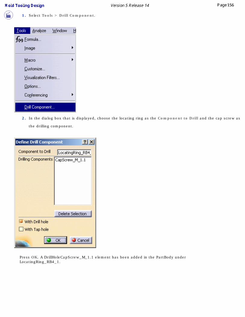
1. Select Tools > Drill Component.
2. In the dialog box that is displayed, choose the locating ring as the Component to Drill and the cap screw as
the drilling component.
Press OK. A DrillHoleCapScrew_M_1.1 element has been added in the PartBody under LocatingRing_RB4_1.

4. Hide the cap screw to see that the hole has been drilled.
● You can enter a list of drilling components in the Drilling Components field, by picking them either in the viewer
or in the specification tree:

● Each element picked is taken into account once in the list. Picking one element twice does not remove it from the list.
● You can edit this list:
❍ Select one or several drilling component(s) and press the Delete Selection button to remove this selection from the list.
❍ You can now select another component to be added to the list.
The With Tap hole option creates a hole with a thread for the screw whereas the With Drill hole option simply creates the hole.

Drilling a List of Components by Another List of Components
This task shows you how to use a list of components to drill through another list of components.
You need a mold that includes components that have not drilled the plates they have to go through.
1. Open file Product1.CATProduct in the DrillFrom\samples directory.
2. Click on the Drill a list of components icon.

3. Click in the Components to Drill field then select the components that you want to drill (either in
the viewer or in the tree).
4. Click in the Drilling Components field then select the components that you want to drill through
the first group of components (either in the viewer or in the tree).

5. Press OK.
6. Hide the ejector pins to see check that the plates have been drilled.

CatalogsP2 Catalogs are complete for all components.
P1 Catalogs contain the following:● all catalog references for:
❍ cap screws
❍ countersunk screws
❍ dowel pins
❍ locking screws
❍ springs
❍ user components
● one or two samples for:❍ angle pins
❍ bushing
❍ core pins
❍ ejectors
❍ ejector pins
❍ ejector sleeves
❍ eye bolts
❍ flat ejectors
❍ inserts
❍ knock outs
❍ leader pins
❍ retainers
❍ sleeves sliders
❍ stop pins
❍ support pillars
● no references at all for:❍ locating rings
❍ sprue bushing
❍ sprue pullers
❍ babbles
❍ connector plugs
❍ o-rings
❍ gates

Adding your CatalogLinking your Catalog to Another
Using your Catalog

Adding your CatalogThis task shows you how to create your own catalog.
You are going to add:
● a family to a catalog,
● a parts family to a catalog,
● and components to both.
The existing catalogs are:
● Dme
● Dme-America
● Futaba
● Eoc
● Hasco
● Rabourdin
● Strack
● Misumi
● National
● Pedrotti
● PCS
● Meusburger
The catalogs are all metric with the exception of Dme-America and National which are in inches.
For more complete information on the Catalog Editor, please see the chapter on this subject in the Infrastructure manual.
1. Open the catalog editor via Start > Infrastructure > Catalog Editor.
The editor is displayed with a new catalog that has one chapter.


2. Change the name of Chapter.1 to MyComponents by using the contextual menu and Chapter.1 object > Definition.
Now you are going to add a family. A family is composed of any type of part of any type of dimension.
3. Click the Add Family icon .

The Component Family Definition dialog box is displayed. Call the new family Sliders. Click OK. The Sliders family is created under MyComponents in the specification tree. A keyword Sliders is added to the Keywords tab for MyComponents.
4. Now you can add a keyword to Sliders. Double click on Sliders in the tree. Note that their is only one column named
Name in the Keywords tab for the family Sliders, and that it is empty.
Click the Add Keyword icon . The Keyword Definition dialog box is displayed

Create a string type keyword called Ref
Now create two other keywords:
● Length of length type,
● Created by of string type.
Those new keywords define the headings to the columns that are created in the catalog table.
If you wish to configure the component when creating it, the names of keywords should be exactly identical to the names of the parameters used in the Design Tables.
5. Click the Add Component icon .
In the dialog box that is displayed, go to the Keyword values tab. Select each Keyword line and replace the default value in the Value field as follows:
● Slider1 for Name,
● Slider_DS01 for Ref,
● 25 mm for Length,
● Your name for Created by.

Now go to the Reference tab and press the Select Document button.
Use the browser to select the file Slider_1.CATPart in the Samples/Catalog directory.
Press OK to confirm. The Keywords tab is updated.
You can now do the same with Slider_2.CATPArt and the values below:

6. A Part family is composed of one shape of part of different dimensions. In order to add more part families, double click
on the MyComponents chapter then Click the Add a Part Family icon . The Part Family Definition dialog box is
displayed.
Call the new family WearPlates.
Add a component to this family by pressing the Select Document button and choosing WearPlate.CATPart in the samples/catalog directory. Click OK.
The WearPlates family is created under MyComponents.
Double-click WearPlates to see the associated keywords:
7. Save your catalog (File > Save as) in the directory of your choice.

You can now create a catalog of gates. It can include side and submarine type gates. When creating a gate catalog, you must ensure that you define both types of gates as families before adding new gates to them.

Linking your Catalog to AnotherThis task shows you how to link one of your own catalogs to another so that the contents of you catalog can be seen when you open the other one.
1. Open the UserComponent.catalog in the
downloaddirectory/OS/startup/components/MoldCatalog directory (where downloaddirectory is the
directory where you downloaded the application).
2. Open the MyComponents.catalog file that you created in the previous chapter (or if you didn't,
open the MyComponents.catalog file in the samples/catalog directory).
3. Click the UserComponent.catalog window and then click the Add link to other catalog icon
.

4. In the MyComponents.catalog, select the MyComponents chapter.
You can now access your catalog components from the UserComponent.catalog.
5. Save the UserComponent.catalog file with File > Save in the directory of your choice.

Using your CatalogThis task shows you how to use one of your own catalogs.
1. Open the MoldUserComponents.CATProduct file in the samples/catalog directory.
2. Click the Add User Component icon . This opens the catalog browser. Press the catalog icon
to access the catalog browser.
Then press the folder icon to browse your directories to reach the UserCatalog you have linked with your
catalog in the previous task.
The user component catalog is displayed with the MyComponent chapter that you created.

You can now use the components in your catalog.

Generating the Bill of MaterialThis task shows you how to generate the bill of material for your project.
1. Open file MoldWithMoldedPartAndComponents.CATPoduct in the sample/MoldAndPart directory.
2. Select the product, then the Analyze, Bill of Material menu. The dialog box is displayed:

3. Press the Define Formats button to choose the fields you want in your bill of material, i.e. the Displayed properties:
● Quantity (number of items),
● Part Number (the name of the part),
● Nomenclature (supplier reference),
● Product Description (name of the supplier),
● Material (name of the material),
● HeatTreat (type of heat treatment),
● and Source (whether the item was made, bought or unknown).

To do so, select the lines you want to remove from the Displayed properties list and press >| to send them to the Hidden properties list then select the lines
in the Hidden properties list that you want to send to the Displayed properties and press |<.

and press OK when your selection is satisfactory.
The Bill Of Material tab now looks like this:

4. Press the Save as ... button to select the directory where you want to save your bill of material.

You can modify the properties of a component by selecting it in the specification tree, selecting Properties in its contextual menu, going to the Product tab and choosing the value you want for your component's source.

Saving Data
This task shows you how to save your data once you have created your mold.
There are several possibilities. You can:
● define the directory where you want to send all of your data during your work session. This must be done as soon as you start a session,
● save the CATProduct only with File > Save or File > Save as.
● or you can send everything to a directory when you save your data (during or at the end of your session).
1. Create a directory where you want to store your data.
2. Use File > Save Management.

3. Choose the target directory and push the Propagate directory button. Click OK, the saving starts and all of the components that make up your mold are now
in the MyNewMold directory.

Using other WorkbenchesMold Kinematics
Checking Clash and ClearanceUsing Drafting Functionalities
Using Prismatic Machining FunctionalitiesUsing Surface Machining Functionalities

Mold Kinematics
DMU Kinematics is used to simulate the opening of the mold. The mold assembly has been designed so as to enable an automatic extraction of the kinematics data, taking advantage of all the assembly constraints that have been defined between all the components (including sliders) in the mold.
Kinematics as used in most cases
1. Open your file and make sure that the product including the molded part and the mold is active in the specification
tree.
2. Select the Edit, Links item. Then select the mold product in the panel. Open it.
3. Switch to DMU Kinematics. Pick the Assembly Constraints Conversion icon .
Push the New Mechanism button, then the Auto Create button. Four joints are created in the specification tree:

4. Double-click on one joint. Check the Driven Length option in the panel. Repeat the operation on the second joint.
A message indicates that the simulation can be started:
5. Click the simulation icon, and select the newly created mechanism. For more information, refer to DMU Kinematics
documentation.

Kinematics with sliders
Ensure that in the cavity plate on the injection side that you have a sketch (for each slider) that represents the path that the slider will follow. The sketch must be continuous and connected by minute fillets.
You will also need to create offset constraints for each slider that will serve to move the slider out of its slot.
1. Open file KinematicSlider.CATProduct in the samples/KinematicSlider directory.

2. Select Edit >Links. Then select the mold product in the panel. Open it.
3. Switch to DMU Kinematics. Pick the Assembly Constraints Conversion icon .
Push the New Mechanism button, then the Auto Create button, then OK. Two joints are created in the specification tree:
4. Double click on the joint called Prismatic.1 in the tree. Check the Length Driven option in the dialog box.
Press OK.

5. For the first slider, click the Point Curve Joint icon .
● In the dialog box, select: ❍ the sketch for the movement of the slider as Curve 1,
❍ the point at the top of the sketch as Point 1.
Check the Length Driven option.
Press OK.
6. Repeat step 5 for the other slider. Do not check the Length Driven option.
A message indicates that the simulation can be started.

Checking Clash and ClearanceThis task shows you how to use DMU Space Analysis to check clearances between ejectors and coolant channels.
1. Open CheckingClashAndClearance.CATProduct in the samples/CheckClash directory.
2. Go to Assembly Design via Start > Mechanical Design. Click the Analyze/Clash icon and
fill in the Check Clash panel like this . Choose the type first (Clearance + Contact + Clash)
then specify that you want an analysis Between two selections.
Then make your selections.

For Selection 1 choose CoolingBody in the specification tree
Then click on the field for Selection 2 and choose EjectorSystem in the specification tree,

3. Click Apply to view the results of the clearance analysis between the coolant channels and the
ejector system. As you can see below there are two problems. Click on the first one to display the
actual problem.

Now Zoom in the preview window (as in any viewer) and you will see that the problem is a distance of 2.26 mm between the CoolingBody and the EjectorSystem which is too close because a minimum distance of 5 mm was defined in the Check Clash dialog box.
The Interference analysis and its results are now in the specification tree. They remain visible when you switch back to Mold Design. You can select them and activate them directly from this application.
For more information, refer to DMU Space Analysis documentation.

Using Drafting FunctionalitiesAll mold data is based on CATProducts and CATParts which can be directly used with Drafting functionalities.

Using Prismatic Machining FunctionalitiesOnce a mold has been designed, it should be machined, with the exception of standard components that were purchased from a supplier.
Prismatic Machining should be used to machine holes and pockets (this mainly concerns plates).

Using Surface Machining FunctionalitiesOnce a mold has been designed, it should be machined, with the exception of standard components that were purchased from a supplier.
Surface Machining should be used to machine the shape of the part to mold (this concerns mainly the core and cavity).

Mold Tooling Design Workbench DescriptionThis is what the Mold Tooling Design workbench looks like:
Menu BarTool Bars
Specification Tree

Mold Tooling Design Menu Bar
Start SmarTeam File Edit View Insert Tools Analyze Windows Help
The menus specific to the Mold Tooling Design application are the following:
Edit
For See
Copy Reference Copying a Component Reference
Replace Component Replacing Components
Insert
Mold Base Components
Creating a Mold Base
Guiding Components Standard mold components

Locating Components Standard mold components
Fixing Components Standard mold components
Ejection Components Standard mold components
Injection Components Standard mold components
Miscellaneous Components Standard mold components
Tools
Options...
Customization
Drill Component...
Explode Holes
Drilling Components
Explode Holes

Analyze
Bill of Material
Generating the Bill of Material

Mold Tooling Design Creation Tool BarsTools dedicated to the creation of mold components are:
Mold Base ComponentsGuiding ComponentsLocating ComponentsFixing Components
Ejection ComponentsInjection Components
Miscellaneous ComponentsManipulationDrill Tools

Mold Base Components
For See
Mold Plates; Creating a Mold Base
New Mold Plate; Adding a plate to a mold
New Slider; Standard mold components
New Retainers; Standard mold components
New Insert; Adding an insert to a mold

Guiding ComponentsFor See
LeaderPin; Standard mold components
Bushing; Standard mold components

Locating Components For See
Sleeve; Standard mold components
Locating Ring; Standard mold components
Dowel Pin; Standard mold components

Fixing Components For See
CapScrews Standard mold components
CountersunkScrew; Standard mold components
LockingScrew; Standard mold components

Ejection ComponentsFor See
EjectorPin; Standard mold components
Ejector; Standard mold components
FlatEjector; Standard mold components
EjectorSleeve; Standard mold components
CorePin; Standard mold components
StopPin; Standard mold components
AnglePin; Standard mold components
KnockOut; Standard mold components

Injection Components For See
SprueBushing; Standard mold components
SpruePuller; Standard mold components
Support Pillar; Standard mold components
O-Ring; Standard mold components
Plug; Standard mold components
Baffle; Standard mold components
Gate; Gates
Runner; Runners
Coolant Channel; Coolant channels

Miscellaneous Components For See
User Component; Standard mold components
EyeBolt; Standard mold components
Spring; Standard mold components

Manipulation
For See
Manipulation; Manipulate Components
Snap; Snap Components

Drill Tools
For See
Drill List Drilling a List of Components by Another List of Components
;

Specification Tree
The icons displayed in Mold Design specification tree are standard icons.
You can choose to show or hide parameters, relations and constraints using the following menus: ● For CATProducts (Mold, InjectionSide, EjectionSide, EjectorSystem): Tools->Options->Infrastructure->Product
Structure:
● For CATParts: Tools->Options->Infrastructure->Part Infrastructure:
The rules below should be complied with for a better use of Mold Design. You can create molds without following these rules, but this may lead to unexpected results and performances.

Mold
InjectionSide, EjectionSide and EjectorSystem are CATProducts
The compulsory names for plates are:
● ClampingPlate,
● UpperBar1, UpperBar2,
● CavitySupportPlate,
● CavityPlate,
● StripperPlate,
● CorePlate,
● CoreSupportPlate,
● RiserBar1, RiserBar2,
● SettingPlate,
● EjectorPlateA, EjectorPlateB

MoldedPart
The Part Number of the part to mold must be MoldedPart
MoldedPart must contain the part to mold and all surfaces required for the core plate and cavity plate split. The Geometrical set containing the parting surface must be called PartingBody.
When splitting a component, all bodies included in the component will be split. If there is a body that you do not want to split, rename it with two underscores as a prefix (i.e. body1 becomes __body1).
If a surface named CavitySurface is found in the specification tree, it will be automatically proposed as the splitting element for the cavity plate.
If a surface named CoreSurface is found in the specification tree, it will be automatically proposed as the splitting element for the core plate.
Predefined 3D points Standard mold bases include
3D points that are identified as being for the location of components; Points for:
● bushings are called Bushingi (where i is a number from 1 to 4),
● cap or countersunk screws are called ClampingScrewi, SettingScrewi and EjectorBScrewi (where i is a number from 1 to 4),
● leader pins are called LeaderPini (where i is a number from 1 to 4),
● sleeves are called Sleevei (where i is a number from 1 to 4),

● stop pins are called StopPini (where i is a number from 1 to 4).


UserComponent This is a CATPart with a special structure
Its name must be that used in the catalog (here SLIDER)
There must be an Geometrical set named PartBody containing the object itself.
There must be an Geometrical set named DrillHoll containing the negative shapes subtracted from the mold.
There must be an Geometrical set BaseBody containing a point named Base, with its coordinates being 0,0,0 to define the reference point of the component.
To add material around a component, you must create an Geometrical set named Pad.
To remove material around a component, you must create an Geometrical set named Pocket.

Customizing
Before you start your first working session, you can customize the way you work to suit your habits. This type of customization is stored in permanent setting files: these settings will not be lost if you end your session.
1. Select the Tools -> Options command. The Options dialog box displays.
2. Choose the Mechanical Design category in the left-hand box, then Mold Tooling Design.
You will find the Mold Tooling Design options in the following tabs:
● General, that defines the storage location of catalogs,
● Component, that defines the components options.

3. Set options in these tabs according to your needs.
4. Click OK when done.

General
Catalog storage Directory in the General tab is the directory where the root catalogs are stored. This field
may not be empty. A default directory is proposed. You can add other root catalog storage directories according
to your needs. Separate each path by a ";".

Component
The whole table looks like this:

● The column 'Not cut in section views' is used to determine whether the component will be visualized in
crosshatch display when a cut is being performed in its drafting.
By default, all types of screws (cap screws, countersunk screws, locking screws,...) and dowel pins are not cut; therefore the option is selected by default for these components
● The column Selection filter allows the user to activate or not know-how rules when creating components.
When activated, associated filters are applied in the Catalog Browser during component creation.
By default, the rules are automatically applied to all components:
● bushing: the value of the inner diameter of the bushing (InD) must correspond to the value of the leader pin 's tip diameter (D) if there is one.The following filter is therefore activated: InD=D
● core pin: the overall length of the core pin (L) must be greater than or equal to H, the height between the bottom of EjectorPlateA and the top of the uncut CorePlate. The following filter is therefore activated: L>=HAlso, the height of the core pin's guide hole is set by the Offset_Parting parameter.
● ejector: the overall length of the ejector (L) must be greater than or equal to H, the height between the bottom of EjectorPlateA and the top of the uncut CorePlateThe following filter is therefore activated: L>=HAlso, the height of the ejector's guide hole is set by the Offset_Parting parameter.
● ejector pin: the overall length of the ejector pin (L) must be greater than or equal to H,

the height from the bottom of EjectorPlateA to the top of the uncut CorePlate.The following filter is therefore activated: L>=HAlso, the height of the ejector pin's guide hole is set by the Offset_Parting parameter.There is a check on the height value of the hole containing the ejector pin's shouldered part to determine whether it is consistent with the course of the ejection plates; an error message is displayed when there is a risk of collision.
● ejector sleeve: the overall length of the ejector sleeve (L) must be greater than or equal to H, the height from the bottom of EjectorPlateA to the top of the uncut CorePlateThe following filter is therefore activated: L>=HAlso, the height of the ejector sleeve's guide hole is set by the Offset_Parting parameter.
● flat ejector: the overall length of the flat ejector (L) must be greater than or equal toH, the height between the bottom of EjectorPlateA and the top of the uncut CorePlate.The following filter is therefore activated: L>=HAlso, the height of the flat ejector's guide hole is set by the Offset_Parting parameter.There is a check on the height value of the hole containing the flat ejector's shouldered part to determine whether it is consistent with the course of the ejection plates; an error message is displayed when there is a risk of collision
● leader pin: in the case of a standard mold base, use of the DLP diameter parameter (a mold base parameter which is displayed in the specification tree) is recommended by the supplier.The following filter is therefore activated: D=DLP;
● locating ring: in the case of a standard mold base, use of the DLR diameter (a mold base parameter which is displayed in the specification tree) is recommended by the supplier.The following filter is therefore activated: ShD=DLR
● sleeve: the inner diameter of the sleeve (InD) must correspond to the diameter of the leader pin (D) if there is one. The following filter is therefore activated: InD>=DThe length of the sleeve (L) must be greater than the height of the riser bars (H). The following filter is therefore activated: L>H.One or two filters can be activated, depending on the current situation.
● stop pin: in the case of a standard mold base, use of the DSP diameter (a mold base parameter which is displayed in the specification tree) is recommended by the supplier. The following filter is therefore activated: ShD=DSP
● support pillar: the length of a support pillar (L) must equal the height of the riser bars, i.e. the distance between SettingPlate and CoreSupportPlate or CorePlate.The following filter is therefore activated: L=H
● The column Several Instances per Reference is set to yes by default for all components (except for core
pins, ejectors, ejector pins, flat ejectors, ejector sleeves , spring, sliders, and inserts). This is an option that
allows you to create several instances of one reference component. If you deactivate this option, only one
instance will be created per reference component.
● The column Default plate defines a default plate for a given component. By default it is set to None. Select
the component, then select a plate from the Plate name list at the bottom.

● The column Plate Position defines a default positioning on a plate for a given component. By default, this
option is set to Bottom. Click the label to change it to Top. First select the plate on which the component is to
be positioned. The Top and Bottom option becomes available. Check the proper one. The next time you will
create a component of this type, it will be positioned on the chosen plate, on the selected face, without
selecting it.

Methodology
This section provides methodology on the following Mold Tooling Design.
Inserting a Loose CoreUsing a Rule
Using Assembled Components

Inserting a Loose CoreThis task shows you how to insert a loose core component on your own mold base. A loose core is seen as a User Component.
This is only a virtual example on how to proceed, you have to adapt it to your own cases.
1. Click the Create a new mold icon .
2. By default, the following dialog box is displayed. Change the Dimensions, Length to 296 mm,
Width to 196 mm and the Ejector width to 102 mm:
Hide the InjectionSide.

3. Click the Add User Component icon .
4. Select the Lifter.

Pick EjectorPlateA.1. The sketcher is displayed. Pick a point near the undercut of your molded part. The loose core is visualized.
Select CorePlate as the Drill To element. Check that the loose core direction is correct or push the Reverse Direction.
You can use the manipulators to modify the position of the loose core.

4. You can tune up the parameters in the Parameters Tab according to your needs.

5. Click OK once you are satisfied with your settings. The loose core is created.

Using a RuleThis task will show you how to insert an ejector and how to manage the height of its guiding hole with a rule.
1. Open the MoldProduct.CATProduct from the samples/Rule/MoldBase directory.
In the specification tree, you see the Mold (Mold.1) and the MoldedPart (MoldedPart). In MoldedPart, under
Publications you find the published CoreSurface, i.e. the parting surface between core and cavity. If you expand
CorePlate, you will see ExternalReferences that enables the synchronization with the molded part.
We are going to insert an ejector that is split by the CoreSurface. We will activate a rule that will manage the guiding
height of the ejector in respect of its position and of the CoreSurface shape.
2. Click the Add Ejector icon . Click the File Open icon in the dialog box. In the File Open box, browse the samples
directories and select Ejector_A_1.CATPart in the samples/Rule/Component directory.

Select the top face of EjectorPlateB.
The sketcher is displayed, with a manipulator to position the ejector:
The Drill from field is updated with EjectorPlateB. Still in the sketcher, select CorePlate as To.
3. Go to the Parameters tab. Press the rule catalog icon and select the MTDRule.catalog in the samples/Rule/Component
directory.

In the following dialog boxes, double-click OffsetParting then RuleForOffsetParting. Press OK.
Make sure the Activate Rule option is checked. Press OK. The ejector is created. Whatever its location, the height of of the guiding hole has always the same value, defined by the parameter named Offset_Parting.
4. Select Edit Ejector component in the contextual menu of Ejector_A_1_1.1

Change the position of the ejector and press OK. Update your model if necessary. You see that the height of the guiding hole is split according to its position and the CoreSurface shape, and has always the same value.
You see the preview of the new split
Result

The ejector we use for this example must have been split by a surface named CoreSurface, defined in ExternalReferences.
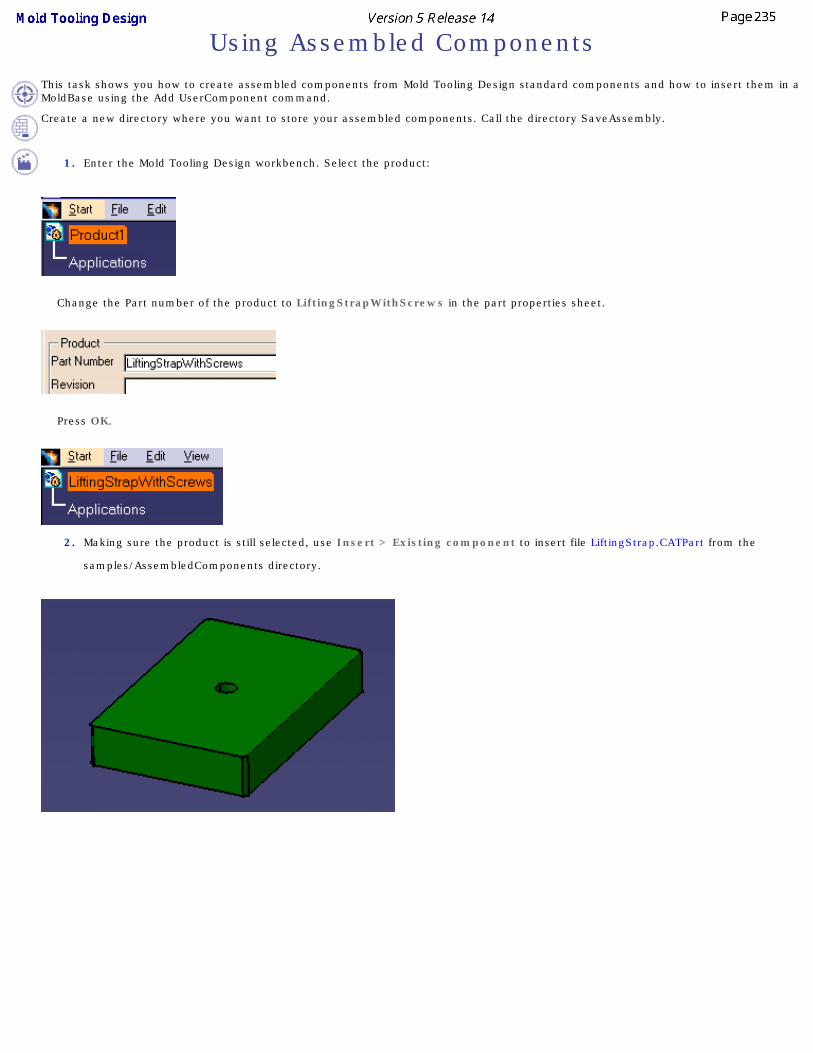
Using Assembled Components This task shows you how to create assembled components from Mold Tooling Design standard components and how to insert them in a MoldBase using the Add UserComponent command.
Create a new directory where you want to store your assembled components. Call the directory SaveAssembly.
1. Enter the Mold Tooling Design workbench. Select the product:
Change the Part number of the product to LiftingStrapWithScrews in the part properties sheet.
Press OK.
2. Making sure the product is still selected, use Insert > Existing component to insert file LiftingStrap.CATPart from the
samples/AssembledComponents directory.

2. Click the Add CapScrew icon and choose a DME M6x40 cap screw. Click on the top surface of the part.
Click once in each corner of the top surface (visible surface) of the part to indicate where you want to locate the screws.
Press OK.

If you hide the cap screws you will see that the holes associated with them have been created.
4. Save your data in the SaveAssembly directory with File > Save Management.
Press the Propagate directory button to save the CATParts.
Press OK.
Close the file with File > Close.
5. Open file AssembledComponents.CATProduct from the samples/AssembledComponents directory.

6. Click the Add User Component icon .
Use the folder icon beside the Reference field to fetch file LiftingStrapWithScrew.CATProduct from your SaveAssembly directory.
Click on the top face of the clamping plate.

Click on the top surface again to position the component.
Change the value of Z to 151.

Press OK.
A constraint is created between the first BaseBody of the first CATPart of the user component and the mold, at its location on the mold. In this example, a new constraint is created between the BaseBody of the LiftingStrap.CATPart of LiftingStrapWithScrew.CATProduct, and the ClampingPlate.

If you hide the user component you will see that the holes associated with it have also been created.
7. You are now going to create a locating ring with screws.
Create a new Product with File > New > Product.
Change the Part number of the product to LocatingRingWithScrews in the part properties sheet.
Insert a new part in the product with Insert > New Part.

8. Go to the Wireframe and Surface workbench.
Select the part that you have just added and click the Point icon.
Press OK.
9. Double click on LocatingRingWithScrews to come back to the Mold Tooling Design workbench.
Click the Add Locating Ring icon and choose a DME LocatingRing R100/R-101.
Expand the tree and select the point you just created.
Press OK.

10. Now add two cap screws.
Click the Add CapScrew icon and choose a DME M8x18 cap screw.
Click on the top surface of the locating ring.
Turn the locating ring round so that you can select the axes of the existing holes for the screws.
Press on Reverse direction in the Cap Screw definition dialog box.
Press OK.

11. Delete the part that contained the point.
12. Save your Product (File > Save Management) in your SaveAssembly directory.

Glossary
Bbill of material a list of data concerning the properties of components
Ccavity surface the surface defining the shape of the mold on the cavity side
coolant channels these channels are positioned on the core, they cool the molded part
core surface the surface defining the shape of the mold on the core side
Eejection side the set of elements (plates and components) located on the mobile side of the injection
machine
ejector system the set of ejection elements (plates and components) located on the ejection side
Ggate the end node of a runner, on the molded part side
Iinjection side the set of elements (plates and components) located on the side where the material is
injected (between clamping and cavity)
insert a component that can be added to the core plate or cavity plate and which can be pierced by coolant channels and attached by other components (such as screws)
Mmold base the set of plates that makes up the mold.
Ooverlap core and cavity overlap; where the part is positioned before the core-cavity split.
Pparting line the outer boundary of the molded part where no undercut is found.
parting surface the surface delimiting the separation between core and cavity
R

runner the channel between sprue bushing and molded part, allowing the filling of the mold by the plastic
Ssplit the operation consisting in generating the parting surface on the core and cavity
standard component the component picked in a supplier catalog
Uuser component the component picked in a user's catalog

Index
AA
Coolant channel
Gate Add
Catalog
Component
Family
Insert
Keyword
MoldPlates
Part family
User component Add AnglePin
command Add Bushing
command Add CapScrew
command Add Component
command
Add Components
Associated
Create several Instances
Drilling holes
First reference
Grid Snap to Point
in an Empty CATProduct
Length of screws
Manage All

Parameters
Position sketch plane parallel to screen
Reverse direction
Rules
Several Instances per Reference
Specifics Add Coolant Channel
command Add CorePin
command Add CountersunkScrew
command Add Dowel Pin
command Add Ejector
command Add Ejector Pin
command Add EjectorPin
command Add EjectorSleeve
command Add EyeBolt
command Add FlatEjector
command Add Gate
command Add Insert
command Add Keyword
command Add KnockOut
command Add Leader Pin
command Add LeaderPin

command Add link to other catalog
command Add Locating Ring
command Add LockingScrew
command Add Mold Plate
command Add New Instance
command Add or Remove material
Pad
Pocket Add O-Ring
command Add Plug
command Add Retainers
command Add Runner
command Add Sleeve
command Add Slider
command Add Spring
command Add SprueBushing
command Add SpruePuller
command Add StopPin
command Add Support Pillar
command Add User Component

command Adding a component
to an existing mold Analyze Clash
command
Analyze Holes in Plates
Angle pin
Angle pin hole diameter
Angle pin positioning angle Angle slant
Gate AnglePinD
Component parameter AnglePinPos
Component parameter AP
Component parameter Aperture angle
Gate Assembled components
Using Assembly Constraints Conversion
command Associated
Add Components
BBaffle Bill of Material
command Bottom angle
Coolant channel
Bushing Bushingi
Position Components
CCap screw Catalog
Add
Link to
Catalog storage Directory CavitySurface
Parting parts Check clash dialog box
Clash and Clearance ClampingScrewi
Position Components
Clash and Clearance
Check clash dialog box
Preview window
Results of clearance analysis Color of associated holes
Drilling holes command
Add AnglePin
Add Bushing
Add CapScrew
Add Component
Add Coolant Channel
Add CorePin
Add CountersunkScrew
Add Dowel Pin
Add Ejector
Add Ejector Pin
Add EjectorPin

Add EjectorSleeve
Add EyeBolt
Add FlatEjector
Add Gate
Add Insert
Add Keyword
Add KnockOut
Add Leader Pin
Add LeaderPin
Add link to other catalog
Add Locating Ring
Add LockingScrew
Add Mold Plate
Add New Instance
Add O-Ring
Add Plug
Add Retainers
Add Runner
Add Sleeve
Add Slider
Add Spring
Add SprueBushing
Add SpruePuller
Add StopPin
Add Support Pillar
Add User Component
Analyze Clash
Assembly Constraints Conversion
Bill of Material
Create a new mold
Delete component
Drill a list of components by another list of components

Drill Component
Edit
Edit links
Edit...Component
Explode Holes
Extract
Fill
Insert existing component
Join
Open in new Window
Point Curve Joint
Project 3D Elements
Save Management
Scaling
Sketcher
Split component
Sweep Component
Add
Edit
Rotate
Split Component parameter
AnglePinD
AnglePinPos
AP
CorCavS
D
D1
D2
DepthPocket
Di

Do
Draft
DraftB
EjeW
G
H
HD
HF
HP
HR
HT
InD
L
LF
Lo
LP
MoldL
MoldW
OverL
OverW
Retraction
RisW
RunD
ShD
ShH
SPShH
StripOverlap
ThD
ThL
UppW
W
WF

WR
WT Coolant channel
A
Bottom angle
Counterbore depth
Counterbore diameter
Create
D1
D2
Delete
Edit
Inner diameter
L
Predefined sketch
Preview
Reverse
V
Copying a component reference CorCavS
Component parameter Core and cavity
Split
Core pin CoreSurface
Preparing parts Counterbore depth
Coolant channel Counterbore diameter
Coolant channel
Countersunk screw Create
Coolant channel
Gate

Mold Base
Runner Create a new mold
command Create several Instances
Add Components
Cross section diameter
DD
Component parameter D1
Component parameter
Coolant channel D2
Component parameter
Coolant channel
Default plate Define
Mold base Delete
Coolant channel
Gate
Runner Delete component
command DepthPocket
Component parameter Di
Component parameter
Diameter of thick part
Diameter of threaded part Direct
Gate

Distance between setting and ejector plates Distance between the gate and the cavity measured on the parting surface
Gate Do
Component parameter
Dowel pin Draft
Component parameter DraftB
Component parameter
Drafting functionalities Drill a list of components by another list of components
command Drill Component
command
With hole
With tap Drilling holes
Add Components
Color of associated holes Driven length
Mold Kinematics
EE
Gate Edit
command
Component
Coolant channel
Gate
Hole Edit links
command

Edit...Component
command
Ejection components
Ejector
Ejector pin
Position
Ejector sleeve EjectorBScrewi
Position Components EjeW
Component parameter Explode Holes
command Extract
command
Eyebolt
FFamily
Add Fill
command First reference
Add Components
Fixing components
Flat ejector
GG
Component parameter Gate
A

Angle slant
Aperture angle
Create
Delete
Direct
Distance between the gate and the cavity measured on the parting surface
E
Edit
H
Height
L
L1
Length
Location
Minimum length of the cylindrical nozzle
R
Radius
Radius of the cylindrical nozzle
Section shape
Side
Stamp
Submarine
W
Width
Gate catalogs
Geometry of components Grid Snap to Point
Add Components
Guide rail height
Guide rail length
Guide rail pocket depth
Guide rail width

Guiding components
HH
Component parameter
Gate HD
Component parameter Height
Gate
Height of the plate
Height that the slider form is raised HF
Component parameter Hole
Edit HP
Component parameter HR
Component parameter HT
Component parameter
Iin an Empty CATProduct
Add Components InD
Component parameter
Injection components
Injection features
Injection length
Inner diameter

Coolant channel
Insert
Add Insert existing component
command
Insert height
Insert leader pins
Insert length
Insert width
Insertion diameter
JJoin
command
Preparing parts
KKeyword
Add
KnockOut
LL
Component parameter
Coolant channel
Gate L1
Gate Layout

Runner
Leader pin LeaderPini
Position Components Length
Gate
Length of flat area Length of screws
Add Components
Length of the threaded part
Length of thick part
Length overhang for clamping and setting plates LF
Component parameter Link to
Catalog Lo
Component parameter
Locating components
Locating ring Location
Gate
Locking screw LP
Component parameter
MMain length of the mold
Main width of the mold Manage All
Add Components Many instances by reference
Split Minimum length of the cylindrical nozzle

Gate
Miscellaneous components Mold Base
Create
Slider Mold base
Define
New
Parameters
Standard
User defined
Mold base components
Mold Kinematics
Driven length
Slider offset constraint
Slider path
Slider sketch
Sliders
Mold Tooling Design toolbars
Mold Tooling Design workbench MoldL
Component parameter MoldPlates
Add MoldW
Component parameter
NNaming requirements
Runner New
Mold base

Not cut in section views
OOpen in new Window
command
Oring
Overall length OverL
Component parameter
Overlap between cavity and core plates
Overlap between stripper and core plates OverW
Component parameter
PPad
Add or Remove material Parameters
Add Components
Mold base
Standard components Part family
Add Parting parts
CavitySurface
Parting surface
Preparing parts
Plate Position
Plug Pocket
Add or Remove material Point Curve Joint

command Position
Ejector pin Position Components
Bushingi
ClampingScrewi
EjectorBScrewi
LeaderPini
SettingScrewi
Sleevei
StopPini Position sketch plane parallel to screen
Add Components
Predefined points for components Predefined sketch
Coolant channel
Preparing parts
CoreSurface
Join
Parting surface
Pulling direction
Scaling Preview
Coolant channel Preview window
Clash and Clearance
Prismatic Machining functionalities Project 3D Elements
command Pulling direction
Preparing parts
R

R
Gate Radius
Gate Radius of the cylindrical nozzle
Gate
Replacing components Results of clearance analysis
Clash and Clearance
Retainer
Retainer height
Retainer width Retraction
Component parameter
Retrieve Parameters
Retrieve parts Reverse
Coolant channel
Reverse direction
Add Components RisW
Component parameter Rotate
Component Rules
Add Components RunD
Component parameter Runner
Create
Delete
Layout
Naming requirements
Section shape
Stamp

Support
Runner diameter
SSave data Save Management
command Scaling
command
Preparing parts Section shape
Gate
Runner
Select document
Selection filter SettingScrewi
Position Components
Several Instances per Reference
Add Components ShD
Component parameter ShH
Component parameter
Shoulder diameter
Shoulder height
Shoulder-to-shoulder diameter Side
Gate
Sider guide rail height Sketcher
command
Sleeve Sleevei

Position Components
Slider
Mold Base
Slider draft angle
Slider form height
Slider form length
Slider form width
Slider guide rail width Slider offset constraint
Mold Kinematics Slider path
Mold Kinematics
Slider pocket depth
Slider retraction
Slider shelf angle
Slider shelf height
Slider shelf length Slider sketch
Mold Kinematics
Slider support height
Slider support length
Slider support width Sliders
Mold Kinematics
Specification tree Specifics
Add Components Split
Component
Core and cavity
Many instances by reference Split component
command
Splitting surface

Spring
Sprue bushing
Sprue puller
Sprue stripper plate SPShH
Component parameter Stamp
Gate
Runner Standard
Mold base
Standard components
Parameters
Stop pin StopPini
Position Components StripOverlap
Component parameter
Stripper plate Submarine
Gate Support
Runner
Support pillar
Surface Machining functionalities Sweep
command
TThD
Component parameter ThL
Component parameter

Tip diameter
Tip length to an existing mold
Adding a component Tools Options - Mold Tooling Design
Component
General
UUppW
Component parameter
User catalog
User component
Add
User component requirements User defined
Mold base
User defined gates Using
Assembled components
VV
Coolant channel
WW
Component parameter
Gate WF

Component parameter Width
Gate
Width between the guide rails
Width of ejector plates
Width of flat area
Width of riser bars
Width of upper bars
Width overhang for clamping and setting plates With hole
Drill Component With tap
Drill Component
Workbench description WR
Component parameter WT
Component parameter