Moisture Sensitivity/Desiccant Packaging/Handling of · PDF filevariety of surface mount...
27
2000 Packaging Databook 8-1 Moisture Sensitivity/Desiccant Packaging/Handling of PSMCs 8 8.1 Introduction This chapter examines surface mount assembly processes and establishes preconditioning flows which encompass moisture absorption, thermal stress and chemical environments typical in the variety of surface mount assembly methods currently in use. Also discussed are the standardized moisture sensitivity levels which control the floor life of moisture/reflow sensitive PSMCs along with the handling, packing and shipping requirements necessary to avoid moisture/reflow related failures. Baking to reduce package moisture level and its potential effect on lead finish solderability is described. In addition, drying, shipping, and storage procedures are included. 8.2 Moisture Sensitivity of PSMCs This section addresses technical issues related to maintaining package integrity during board level assembly processing using Plastic Surface Mount Components (PSMC). Surface mount processing subjects the component body to high temperature and chemicals (from solder fluxes and cleaning fluids) during board mount assembly. In through-hole technology the board assembly process uses wave soldering which primarily heats the component leads. The printed circuit board acts as a barrier to protect the through-hole package body from solder heat and flux exposure. Note: No component body should ever be immersed directly in the solder during the wave solder operation. To ensure PSMC package integrity throughout the surface mount process, precautions must be taken by both supplier and user to minimize the effects of reflow solder stress on the component. Plastic molding compounds used for integrated circuit encapsulation are hygroscopic and absorb moisture dependent on time and the storage environment. Absorbed moisture will vaporize during rapid heating in the solder reflow process, generating pressure at various interfaces in the package, which is followed by swelling, delamination and, in some cases, cracking of the plastic as illustrated in Figure 8-1 and Figure 8-2. Cracks can propagate either through the body of the plastic or along the lead frame (delamination). Subsequent high temperature and moisture exposure to the package can induce the transport of ionic contaminants through these openings to the die surface increasing the potential for circuit failure due to corrosion. Components that do not exhibit external cracking can have internal delamination or cracking which impacts yield and reliability. It should be noted that PSMC moisture sensitivity relates only to the risk associated with direct exposure of components to reflow solder process stresses. No loss of package integrity is expected for socketed parts or for through-hole mounted components not subjected to the solder reflow environment. If through-hole components are exposed to SMT processing, then they can exhibit the same moisture sensitivity as PSMCs. If through-hole devices are exposed to solder reflow processes such as Convection, VPS, or IR, then they should be baked dry first, using the same baking procedures described for SMT packages. Current data indicates that there is no negative long term effects on reliability of PSMCs when package integrity is maintained through surface mount processing.
Transcript of Moisture Sensitivity/Desiccant Packaging/Handling of · PDF filevariety of surface mount...

Moisture Sensitivity/Desiccant Packaging/Handling of PSMCs 8
8.1 IntroductionThis chapter examines surface mount assembly processes and establishes preconditioning flows which encompass moisture absorption, thermal stress and chemical environments typical in the variety of surface mount assembly methods currently in use. Also discussed are the standardized moisture sensitivity levels which control the floor life of moisture/reflow sensitive PSMCs along with the handling, packing and shipping requirements necessary to avoid moisture/reflow related failures. Baking to reduce package moisture level and its potential effect on lead finish solderability is described. In addition, drying, shipping, and storage procedures are included.
8.2 Moisture Sensitivity of PSMCsThis section addresses technical issues related to maintaining package integrity during board level assembly processing using Plastic Surface Mount Components (PSMC). Surface mount processing subjects the component body to high temperature and chemicals (from solder fluxes and cleaning fluids) during board mount assembly. In through-hole technology the board assembly process uses wave soldering which primarily heats the component leads. The printed circuit board acts as a barrier to protect the through-hole package body from solder heat and flux exposure.
Note: No component body should ever be immersed directly in the solder during the wave solder operation.
To ensure PSMC package integrity throughout the surface mount process, precautions must be taken by both supplier and user to minimize the effects of reflow solder stress on the component. Plastic molding compounds used for integrated circuit encapsulation are hygroscopic and absorb moisture dependent on time and the storage environment. Absorbed moisture will vaporize during rapid heating in the solder reflow process, generating pressure at various interfaces in the package, which is followed by swelling, delamination and, in some cases, cracking of the plastic as illustrated in Figure 8-1 and Figure 8-2. Cracks can propagate either through the body of the plastic or along the lead frame (delamination). Subsequent high temperature and moisture exposure to the package can induce the transport of ionic contaminants through these openings to the die surface increasing the potential for circuit failure due to corrosion. Components that do not exhibit external cracking can have internal delamination or cracking which impacts yield and reliability.
It should be noted that PSMC moisture sensitivity relates only to the risk associated with direct exposure of components to reflow solder process stresses. No loss of package integrity is expected for socketed parts or for through-hole mounted components not subjected to the solder reflow environment. If through-hole components are exposed to SMT processing, then they can exhibit the same moisture sensitivity as PSMCs. If through-hole devices are exposed to solder reflow processes such as Convection, VPS, or IR, then they should be baked dry first, using the same baking procedures described for SMT packages. Current data indicates that there is no negative long term effects on reliability of PSMCs when package integrity is maintained through surface mount processing.
2000 Packaging Databook 8-1
Moisture Sensitivity/Desiccant Packaging/Handling of PSMCs
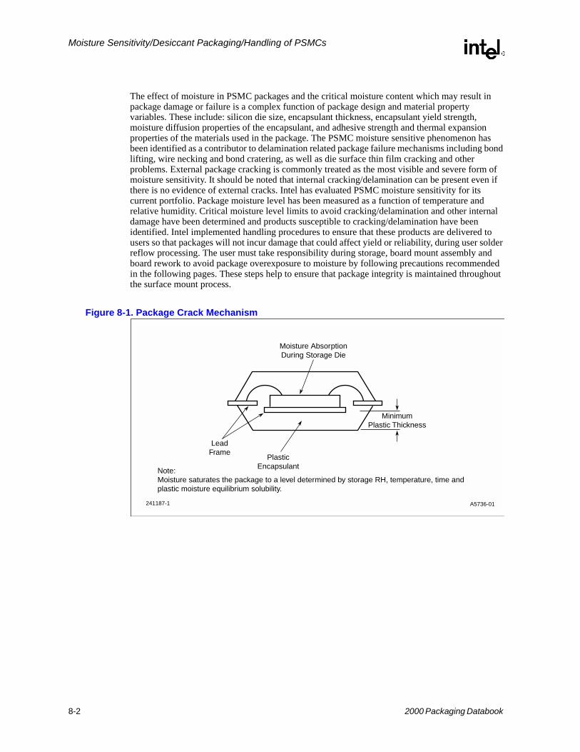
The effect of moisture in PSMC packages and the critical moisture content which may result in package damage or failure is a complex function of package design and material property variables. These include: silicon die size, encapsulant thickness, encapsulant yield strength, moisture diffusion properties of the encapsulant, and adhesive strength and thermal expansion properties of the materials used in the package. The PSMC moisture sensitive phenomenon has been identified as a contributor to delamination related package failure mechanisms including bond lifting, wire necking and bond cratering, as well as die surface thin film cracking and other problems. External package cracking is commonly treated as the most visible and severe form of moisture sensitivity. It should be noted that internal cracking/delamination can be present even if there is no evidence of external cracks. Intel has evaluated PSMC moisture sensitivity for its current portfolio. Package moisture level has been measured as a function of temperature and relative humidity. Critical moisture level limits to avoid cracking/delamination and other internal damage have been determined and products susceptible to cracking/delamination have been identified. Intel implemented handling procedures to ensure that these products are delivered to users so that packages will not incur damage that could affect yield or reliability, during user solder reflow processing. The user must take responsibility during storage, board mount assembly and board rework to avoid package overexposure to moisture by following precautions recommended in the following pages. These steps help to ensure that package integrity is maintained throughout the surface mount process.
Figure 8-1. Package Crack Mechanism
A5736-01241187-1
MinimumPlastic Thickness
PlasticEncapsulant
LeadFrame
Moisture AbsorptionDuring Storage Die
Note:Moisture saturates the package to a level determined by storage RH, temperature, time andplastic moisture equilibrium solubility.
8-2 2000 Packaging Databook
Moisture Sensitivity/Desiccant Packaging/Handling of PSMCs
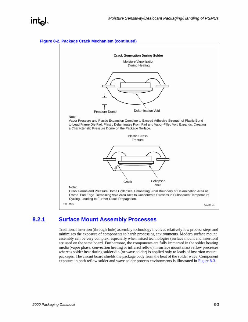
Figure 8-2. Package Crack Mechanism (continued)
8.2.1 Surface Mount Assembly ProcessesTraditional insertion (through-hole) assembly technology involves relatively few process steps and minimizes the exposure of components to harsh processing environments. Modern surface mount assembly can be very complex, especially when mixed technologies (surface mount and insertion) are used on the same board. Furthermore, the components are fully immersed in the solder heating media (vapor phase, convection heating or infrared reflow) in surface mount mass reflow processes whereas solder heat during solder dip (or wave solder) is applied only to leads of insertion mount packages. The circuit board shields the package body from the heat of the solder wave. Component exposure in both reflow solder and wave solder process environments is illustrated in Figure 8-3.
A5737-01241187-3
Moisture VaporizationDuring Heating
Note:Vapor Pressure and Plastic Expansion Combine to Exceed Adhesive Strength of Plastic Bond to Lead Frame Die Pad. Plastic Delaminates From Pad and Vapor-Filled Void Expands, Creatinga Characteristic Pressure Dome on the Package Surface.
Crack CollapsedVoid
Crack Generation During Solder
Delamination VoidPressure Dome
Plastic StressFracture
Note:Crack Forms and Pressure Dome Collapses, Emanating From Boundary of Delamination Area at Frame Pad Edge. Remaining Void Area Acts to Concentrate Stresses in Subsequent TemperatureCycling, Leading to Further Crack Propagation.
2000 Packaging Databook 8-3

Moisture Sensitivity/Desiccant Packaging/Handling of PSMCs
Figure 8-3. Component Exposure to Wave Solder and Reflow Solder Environments
8.2.2 Solder Reflow ProcessesNumerous solder processes are used in attaching components to boards. These range from manual soldering of individual leads with a soldering iron to high volume mass bonding techniques. The primary production methods are pure convection and infrared/convection reflow soldering (IR). Hot bar and VPS are also used in special circumstances. Pure convection is fast becoming standard as it provides more even heating across the board for a wide range of components than does IR. Current revisions of industry moisture sensitivity classificaton standards specify that convection is the preferred method.
Pure convection reflow processing uses convection heating to provide heat for soldering. Electric heaters heat the atmosphere inside the furnace which then heats the boards traveling on the conveyor. A gradual heating of the printed circuit board is necessary to drive off the volatile constituents of the solder paste and ensures a controlled heating rate. After an appropriate preheat time, the board is raised to the reflow temperature for soldering and then carefully cooled down
Vapor Phase soldering uses the latent heat of vapor condensation to provide heat for soldering. Latent heat is transferred to the component as the vapor of the inert liquid condenses on the component. The VPS temperature reaches its maximum possible value at the fluid boiling point (215° C - 219° C). The maximum heating rate of the component on the board occurs when it is initially immersed in the primary vapor, hence control of the heating rate for any component is limited to preheating the part before immersion in the primary vapor zone. Because of very high ramp rates and the high cost of fluids, VPS is used very little in production environments.
IR solder reflow processing uses radiant heating to provide heat for soldering. IR panels heat the board traveling on the conveyor from top and/or bottom.
Hot Bar (Thermode): This is a relatively new process that is ideal for smaller to midsize volumes of SMDs. The component's leads are held in direct contact to a heated clamp or holding device that presses the component into the solder paste and heats the leads to the reflow temperature. The advantage is that the plastic body does not experience the temperature extremes of a full reflow process. This is useful for heat-sensitive components or low volume production that does not warrant the purchase of production machinery and moisture sensitive storage equipment. (See Chapter 9).
A5738-01241187-4
140 C 220 C
220 C Solder ReflowTemperatures
260 C Solder Wave
Through-Hole40 C
SMD220 C˚
˚
˚
˚
˚
˚
8-4 2000 Packaging Databook

Moisture Sensitivity/Desiccant Packaging/Handling of PSMCs
8.2.3 Thermal Shock on ComponentsRapid heating and cooling rates also cause thermal shock. Surface temperature, being higher than the internal body temperatures during heating, results in a temperature differential which generates thermo-mechanical stress. The degree of thermal shock on components is higher in VPS than in IR or convection. The IR soldering profile is usually designed to heat the components at a rate of 2° C - 6° C per second while convection profiles usually heat the components at a rate of <2° C per second. Only limited control can be exerted on the heating rate of components and boards in VPS. The maximum heating rate during VPS is typically much higher (up to 25° C/second). Such high rates of temperature increase can damage components because of the differences in thermal coefficient of expansion (TCE) mismatch between materials. This problem is exacerbated when components have been allowed to become moisture saturated.
Note: No component body should ever be immersed directly in solder during the wave solder operation.
Intel has determined guidelines for mass reflow soldering and post solder reflow component rework which (see Chapter 9) when followed, minimizes thermal shock to packages and meets users' solder reflow requirements.
8.2.4 Solder FluxesFlux used in solder paste or in board pretinning processes is a major source of ionic contamination which can corrode IC chip metallization if transported to the chip surface. Those fluxes containing hydrochloric acid or other halogen compounds should be avoided. (Intel's processes are completely halide free.) Use cleaning methods which ensure complete removal of all flux residues. Avoid highly active fluxes such as organic acid (OA) types. Use RMA or lower activity fluxes whenever possible.
Because of the drive to eliminate CFC-containing materials in solder flux removal, alternative cleaning methods have been under development. Terpene based materials have not shown to cause any long term effects with PSMC components. A relatively recent development is the no-clean or low clean fluxes. These require virtually no cleaning other than a water rinse following SMT reflow.
8.3 Ultrasonic Cleaning of I.C. ComponentsVarious equipment companies are promoting the use of ultrasonic cleaning equipment to remove flux and other residues from finished boards. When cleaning plastic components using the ultrasonic cleaning method, refer to the criteria in Table 8-1.
With Ceramic or Hermetic packages (that have an internal cavity) higher power ultrasonic equipment has been shown to cause damage to the internal bond wires and solder joints when exposed to long cleaning times. Most of these problems have been overcome with the use of the lower power equipment. Each component's user must evaluate their application in light of the criteria in Table 8-1 to determine any reliability jeopardy to the boards.
2000 Packaging Databook 8-5

Moisture Sensitivity/Desiccant Packaging/Handling of PSMCs
8.3.1 Solderability
Intel currently supplies PSMCs with copper lead frames and solder plated (tin/lead) finished leads. A potential for lead finish solderability degradation can occur due to formation of Copper/Tin intermetallics. To meet users' solderability requirements the formation of intermetallics must be minimized. Intel has performed evaluations to determine solderability degradation of PSMC after burn-in and baking, which is necessary to drive out package moisture prior to sealing sensitive products in moisture barrier bags (MBBs). Based on the solderability work done at Intel it is recommended that PSMCs with copper lead frames be baked at high temperature (125°C) for no more than 48 hours by the user. Intel monitors outgoing solderability to ensure that product meets user's solderability requirements.
8.3.2 ConclusionComponent susceptibility to moisture damage can manifest itself in many ways. Some of these can be package cracking, bond lifts, die surface thin film cracking, bond cratering or delamination of internal interfaces. Package cracking is one of the most severe forms of moisture sensitivity. Package cracking has been correlated to be a function of die and package geometry and is aggravated by moisture absorption in the plastic encapsulant. Moisture damage to crack-susceptible components can be minimized through users’ processes if absorbed moisture is kept below critical levels and surface mount process thermal limits are observed. Maximum temperature profiles are recommended for these solder processes to minimize crack jeopardy due to thermal stresses. Moisture absorption and desorption characteristics of these sensitive packages have been characterized and moisture exposures sufficient to induce moisture damage have been determined. Intel bakes level 2a through level 6 PSMC packages dry and seals them in bags with desiccant before shipping*. Level 2 PSMC packages are not required to be baked prior to dry pack. Recommended shelf life, storage conditions, floor life, maximum reflow temperatures, redrying and handling procedures are described on the bag and in this Packaging Databook. The user must limit exposure of moisture sensitive components to environmental moisture during SMT assembly and rework processing to keep absorbed moisture below recommended limits and ensure package integrity is maintained throughout the assembly process.
8.4 Guidelines For Handling Units in Desiccant PackIntel ships moisture sensitive PSMCs in a dry state inside moisture barrier bags (MBBs)**. The following information describes the appearance and handling of components shipped in desiccant packing and the materials involved. The handling information applies only to those devices subjected to SMT processes. Handling information covers dry component storage life, manufacturing floor life (of exposed components), rebagging information and guidelines for rebaking units if necessary. Additional information/requirements can be found in IPC/JEDEC J-STD-033 "STANDARD FOR HANDLING, PACKING, SHIPPING AND USE OF MOISTURE/REFLOW SENSITIVE SURFACE MOUNT DEVICES."
Table 8-1. Ultrasonic Cleaning
Power of Ultrasonic Cleaner < 30 Watts per Liter
Ultrasonic Range 39 KHz to 66 KHz
Cleaning Time 3 Minutes per Cycle for 5 Cycles Not to Exceed a Total of 15 Minutes
* 32-lead and 40-lead TSOP packages are not shipped bake and bag.** 32-lead and 40-lead TSOP packages are the only exceptions to this practice.
8-6 2000 Packaging Databook

Moisture Sensitivity/Desiccant Packaging/Handling of PSMCs
8.4.1 Packing MaterialsMoisture sensitive PSMCs packed in tubes, tape and reel or trays are shipped in desiccant packing. Each shipping medium contains units that have been baked as required and are enclosed in sealed Moisture Barrier Bags (MBBs) with desiccant pouches.
• Shipping Box. The label on the shipping box indicates that desiccant packed material is included (see Figure 8-4). This label indicates the seal date of the enclosed MBB and, thereby, the remaining shelf life. Quantities of units shipped per box also differs to accommodate the additional packing materials for shipments in tubes.
Figure 8-4. Example of a Barcode Label
• Moisture Barrier Bag (MBB). Inside the shipping box is a MBB containing components. The bag is strong, ESD-safe, and allows minimal moisture transmission. It is sealed at the factory and should be handled carefully to avoid puncturing or tearing of the materials. A Caution Label (Figure 8-5) and a Barcode label on the bag outlines precautions that should be taken with desiccant packed units.This bag protects the enclosed devices from moisture exposure and should not be opened until the devices are ready to be board mounted. Section 8.5, Supporting Technical Information in this document provides information on the technical aspects of the bag and characterization information.
• Desiccant. Each MBB contains pouches of desiccant to absorb moisture that may be present in the bag. The Humidity Indicator card (Figure 8-6) should be used as the primary method to determine whether the enclosed parts have absorbed excessive moisture.Do not bake or reuse the desiccant once it is removed from the MBB.
• Humidity Indicator Card (HIC). Along with the desiccant pouches, the MBB contains a humidity indicator card (HIC). This card is a moisture indicator and is included to show the user the approximate relative humidity level within the bag. A representation of the HIC is shown in Figure 8-6. If the 20% dot on the card is pink and the 30% dot is not blue, then the components have been exposed to moisture beyond the recommended limits for use in an SMT process. If this should happen, then to use these units safely in a surface mount application, the units should be baked dry (see Section 8.5.2 Rebaking of PSMCs). New cards being phased in will indicate that rebake is needed if the humidity has exceeded 10%. The HIC is reversible and can be reused. Recommendations to avoid expiration of the HIC and the need to rebake units are included in Section 8.4.3.
A5739-01241187-51
(1B) BOX ID: AA0009 50(P) CUST PROD:
(V) SUPPLIER:
LEVEL HOURS(1P) IPN:
(S) SPEC:
(1T) LOT:
(1T) LOT:
(Q) QTY
(Q) QTY
(9D) DATE
(9D) DATE
(R) ROM CODE:R
BAG SEAL DATE 23JAN95
AS
SE
MB
LED
IN M
ALA
YS
IA
2000 Packaging Databook 8-7

Moisture Sensitivity/Desiccant Packaging/Handling of PSMCs
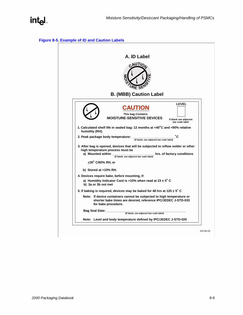
• Labels. Labels relevant to this process are the “Barcode label”, “Caution label” and “ID label” mentioned in the section on MBBs. The Barcode label (Figure 8-4) contains the date that the bag was sealed (MM/DD/YY), the IPC/JEDEC J-STD-020 Moisture Sensitivity level and the maximum floor life is attached to the outside of the box and on the MBB itself. The remaining storage life of the units in the bag is determined from the seal date. All components are guaranteed 12 months of shelf life starting from the seal date on this label. See Section 8.4.3.The Caution label (Figure 8-5) is attached to the outside of the MBB and outlines precautions that must be taken when handling desiccant packed units if they are to be kept dry. The ID label is placed on the same end of the container as the barcode label.
Note: Starting in 2000 Barcode and Caution Labels that indicate the maximum reflow temperature allowed will be phased in.
8-8 2000 Packaging Databook
Moisture Sensitivity/Desiccant Packaging/Handling of PSMCs
Figure 8-5. Example of ID and Caution Labels
A5740-02
CAUTION
MO
IS
TURE SENSITIV
E
Note: Level and body temperature defined by IPC/JEDEC J-STD-020
LEVEL
If blank see adjacentbar code label
CAUTIONThis bag Contains
MOISTURE-SENSITIVE DEVICES
A. ID Label
B. (MBB) Caution Label
1. Calculated shelf life in sealed bag: 12 months at <40˚C and <90% relative humidity (RH).
2. Peak package body temperature: ________________________˚C
5. If baking is required, devices may be baked for 48 hrs at 125 ± 5˚ C
Bag Seal Date: _____________________________________________
Note: If device containers cannot be subjected to high temperature or shorter bake times are desired, reference IPC/JEDEC J-STD-033 for bake procedure.
3. After bag is opened, devices that will be subjected to reflow solder or other high temperature process must be
a) Mounted within ________________________ hrs. of factory conditions
<30˚ C/60% RH, or
b) Stored at <10% RH.
(If blank, see adjacent bar code label)
(If blank, see adjacent bar code label)
(If blank, see adjacent bar code label)
4. Devices require bake, before mounting, if:
a) Humidity Indicator Card is >10% when read at 23 ± 5˚ Cb) 3a or 3b not met
2000 Packaging Databook 8-9

Moisture Sensitivity/Desiccant Packaging/Handling of PSMCs
Figure 8-6. Example of a Humidity Indicator Card
8.4.2 Packing of Shipments
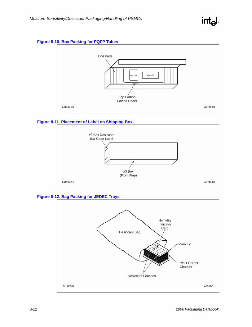
• Tubes. Units shipped in tubes are packed with an additional precaution. Antistatic foam protects the bag from the sharp edges of the tubes and tacks. Otherwise, the units shipped in tubes are packed with materials as indicated in Figure 8-7 through Figure 8-11.
• Trays. Units shipped in injection-molded trays are packed with additional precaution. Antistatic foam lids enclose the trays to protect the bag from the sharp edges of the trays. Trays are packed with materials as indicated in Figure 8-12 through Figure 8-14. (See “Tray Recycle Program” in Chapter 10.)
• Tape and Reel. Units shipped in tape and reel are packed as indicated in Figure 8-15 through Figure 8-17.
Figure 8-7. Bag Packing for PLCC Full or Half Length Tubes
A5741-01241187-6
Humidity Indicator
ExamineItem
if Pink
ChangeDesiccant
if Pink
30
20
Warningif Pink 10
Discard if circles overrunavoid metal contact
A5742-01241187-7
FoamCavity
DesiccantPouches
HumidityIndicator
Card
8-10 2000 Packaging Databook

Moisture Sensitivity/Desiccant Packaging/Handling of PSMCs
Figure 8-8. Box Packing for PLCC Tubes
Figure 8-9. Bag Packing for PQFP Tubes
A5743-01241187-29
Fold Flaps Over
Bubble Wrap
Jedec Tray Box
A5744-01241187-9
DesiccantPouches
Humidity Indicator
Desiccant Bag
Foam End Cap
2000 Packaging Databook 8-11
Moisture Sensitivity/Desiccant Packaging/Handling of PSMCs
Figure 8-10. Box Packing for PQFP Tubes
Figure 8-11. Placement of Label on Shipping Box
Figure 8-12. Bag Packing for JEDEC Trays
A5745-01241187-10
ABCDEF ABCDEF
Top PortionFolded Under
End Pads
A5746-01241187-11
#3 Box(Front Flap)
#3 Box DesiccantBar Code Label
A5747-01241187-12
Foam Lid
Pin 1 CornerChamfer
Desiccant Pouches
HumidityIndicator
CardDesiccant Bag
8-12 2000 Packaging Databook

Moisture Sensitivity/Desiccant Packaging/Handling of PSMCs
Figure 8-13. F Box Packing for JEDEC Trays
Figure 8-14. Placement of Label on JEDEC Tray Box
A5748-01241187-13
Top PortionFolded Under
JEDEC Tray Box
To Box
A5749-01241187-14
JEDEC Tray Box(Front Flap)
#3 Box DesiccantBar Code Label
2000 Packaging Databook 8-13

Moisture Sensitivity/Desiccant Packaging/Handling of PSMCs
Figure 8-15. Bag Packing for Tape and Reel
Figure 8-16. Box Packing for Tape and Reel
A5750-01241187-15
ReelHumidity Indicator
Card
Desiccant Pouches
Desiccant Bag
A5751-01241187-16
Tape & Reel"Pizza" Box
(With Bubble Wrapand End Foams)
CornersFoldedUnder
ABCDEF
ABCDEF
8-14 2000 Packaging Databook

Moisture Sensitivity/Desiccant Packaging/Handling of PSMCs
Figure 8-17. Placement of Desiccant Included Label on Tape and Reel Box
8.4.3 HandlingThe following information details handling procedures that should be used with PSMCs packed in desiccant bags and intended for surface mount applications. Following these handling guidelines will ensure that components maintain their as-shipped, dry state alleviating package cracking and other moisture-related, stress-induced concerns that may be associated with the surface mount process.
1. Incoming Inspection. Upon receipt, shipments should be inspected for a seal date within the last six months. Bag integrity should also be verified. There should not be holes, gouges, tears, or punctures of any kind that expose either the contents or an inner layer of the bag. The barcode label can be reviewed for conformance to the purchase order, but the bag should not be opened until the contents are ready to be used (either inspected or board-mounted). Please see the following Manufacturing Conditions/Floor Life section for details of allowable exposure times once the devices are removed from the bag or exposed to the ambient.
2. Storage Conditions/Shelf Life. The customer receives components in the sealed MBB between 0 and 6 months after the seal date indicated on the Desiccant Barcode label. The sealed bag and enclosed desiccant have been designed to provide a minimum of 12 months of storage (Intel storage time + customer storage time) from the seal date in an environment as extreme as 40° C and 90% relative humidity. The customer will have at least six months of shelf life available on the components without the need to rebake them before use.If the worst-case storage conditions (time, temperature, or relative humidity) are exceeded and there is a need to verify whether inventory has been affected, then a bag can be opened and the HIC can be checked for expiration. If the HIC has not expired, then new desiccant can be added and the bag resealed. If the HIC has expired, then the devices should be 1) rebaked and used in manufacturing within the guidelines outlined in the Rebaking section, 2) rebaked and resealed in an MBB with fresh desiccant, or 3) rebaked and stored in an environment of ≤ 10%RH before they are used in a surface mount process. Please see Rebaking section for additional information.
3. Opening MBBs. To open a moisture barrier bag when the contents are ready to be used or inspected, simply cut across the top of the bag as close to the seal as possible, being careful not to damage the enclosed materials. By cutting close to the seal, you will allow as much room as possible for resealing. Once the bag has been opened, please follow the guidelines for ambient exposure time in the following section to ensure that the devices are maintained below the critical moisture level.
A5752-01241187-17
Tape & Reel Box(Front Flap)
ABCDEF
Reel Box DesiccantBar Code Label
2000 Packaging Databook 8-15

Moisture Sensitivity/Desiccant Packaging/Handling of PSMCs
4. Manufacturing Conditions/Floor Life. Intel is classifying surface mount components into levels of moisture sensitivity. Table 8-2 lists the 8 IPC levels of moisture sensitivity. Note that all levels are based on exposure time and environment. The latest information in the literature and from Intel studies indicates that percent weight gain moisture content is not useful other than for evaluation. Different package types/die attach area/lead count combinations will have different levels of absorbed moisture at which floor life limitations are exceeded. Therefore, Intel recommends that units be classified by allowable exposure times. The labels on the Moisture Barrier Bag lists the Moisture Sensitivity Level and the allowable floor life. See Figure 8-3.Once the barrier bag has been opened, Intel recommends that components be surface mounted and reflowed within the time indicated on the Moisture Barrier Bag label. This time is based on a manufacturing environment not more extreme than 30° C/60%RH and a maximum component body temperature during solder reflow of 220° C. If the component can not be mounted within this timeframe, then they should be put into a dry storage environment immediately, or sealed into a MBB with fresh desiccant as soon as possible. In either case, the remaining allowable ambient exposure time must be reduced by the time the units are out of the MBB or dry storage environment.
If the actual MET is less than 24 hours the soak time may be reduced. For soak conditions of 30 °C/60% RH the soak time is reduced by 1 hour for each hour the MET is less than 24 hours. For soak conditions of 60 °C/60% RH, the soak time is reduced by 1 hour for each 5 hours the MET is less than 24 hours.If the actual MET is greater than 24 hours the soak time must be increased. If soak conditions are 30 °C/60% RH, the soak time is increased 1 hour. for each hour that the actual MET exceeds 24 hours. If soak conditions are 60 °C/60% RH, the soak time is increased 1 hour for each 5 hours that the actual MET exceeds 24 hours.Please contact your local Intel Sales office for specific handling questions. All of the same restrictions for exposure time (outlined above) apply. Reference IPC/JEDEC J-STD-020 “MOISTURE/REFLOW SENSITIVITY CLASSIFICATION FOR NON-HERMETIC SOLID STATE FURFACE MOUNT DEVICES” and IPC/JEDEC J-STD-033 "STANDARD FOR HANDLING, PACKING, SHIPPING AND USE OF MOISTURE/REFLOW SENSITIVE SURFACE MOUNT DEVICES".
Table 8-2. Sensitivity Classification Levels for SMCs
Level Floor LifeSoak Requirements
Standard Accelerated Equivalent
Time Conditions Time (Hours) Conditions Time
(Hours) Conditions
1 Unlimited ≤30 °C/85% RH 168 85 °C/85% RH
2 1 year ≤30 °C/60% RH 168 85 °C/60% RH
2a 4 weeks ≤30 °C/60% RH 6962 30 °C/60% RH 120 60 °C/60% RH
3 168 hours ≤30 °C/60% RH 1922 30 °C/60% RH 40 60 °C/60% RH
4 72 hours ≤30 °C/60% RH 962 30 °C/60% RH 20 60 °C/60% RH
5 48 hours ≤30 °C/60% RH 722 30 °C/60% RH 15 60 °C/60% RH
5a 24 hours ≤30 °C/60% RH 482 30 °C/60% RH 10 60 °C/60% RH
6 Time on Label (TOL)
≤30 °C/60% RH TOL 30 °C/60% RH
NOTES: 1. MET = Manufacturer's Exposure Time: The compensation factor which accounts for the time after bake that the compo-
nent manufacturer requires to process the components prior to bag seal, and including a factor for distribution handling.2. Standard soak time, which includes a default value for semiconductor Manufacturer's Exposure Time (MET) between
bake and bag plus the maximum time allowed out of the bag at the distributor's facility, of 24 hours.
8-16 2000 Packaging Databook

Moisture Sensitivity/Desiccant Packaging/Handling of PSMCs
Where exposure times and/or ambient conditions are difficult to control, Intel highly recommends dry storage capability.
5. In-Process Storage. Intel highly recommends having dry storage capability available for units that will not be used within the allowable exposure time. PLCCs and PQFPs (≤100 leads) can be stored outside of the barrier bag for long periods of time if the ambient relative humidity is less than 10%. This applies to both long term and in-process storage. A desiccator with dry nitrogen or air (≤5%RH source) is suggested for such storage. Desiccator storage conditions for larger PSMCs are currently being established.
6. Rebaking. PSMCs should be rebaked if and only if they have been exposed to excessive moisture as indicated by exceeding the recommended ambient exposure time or by expiration of the HIC.In the event that the units should be rebaked, see Section 8.5.2.
7. Resealing Moisture Barrier Bags. If there is a need to reseal Moisture Barrier Bags for any reason, then Intel recommends the following guidelines to ensure that the bag seal does not allow moisture into the bag. The seal area must not exhibit any separation when subject to load and temperature conditions specified in MIL-B-81705, and must be impermeable to moisture according to MIL-B-81705. Intel uses a seal pressure to 60 psi–70 psi, and a seal time of 3-4 seconds at approximately 225 °C. The integrity of the seal is vital to the storage life of the devices.
Intel ships moisture sensitive PSMCs which have been packed following a tightly controlled process. This flow is shown in Figure 8-18.
Figure 8-18. PSMC Packaging and Bagging Flow Chart
A5753-01241187-18
Text
Mark
Bake
PackageVisual
View Check
FQAVisual
Reject
Scrap
Rework
Desi. PackSeal
Ship Out
2000 Packaging Databook 8-17

Moisture Sensitivity/Desiccant Packaging/Handling of PSMCs
8.5 Supporting Technical InformationThe phenomenon of moisture induced plastic package cracking and internal delamination during high temperature reflow soldering for surface mount has been discussed by several investigators, including Intel. Moisture absorbed to a concentration dependent on the storage environment, can vaporize during the rapid heating of the solder reflow process and generate pressure at internal interfaces in the package. This, along with the stress of thermal expansion mismatches between the leadframe, silicon die and encapsulant, can affect yield and in the more extreme case visible cracking of the plastic will occur. Subsequent exposure to moisture can drive ionic contaminants through these cracks/delaminations to the die surface increasing the potential for device failure due to corrosion.
Once the cracking jeopardy of surface mounted PSMCs was identified, Intel characterized component absorption/desorption rates and saturation limits as a function of temperature and relative humidity. The handling and shelf life guidelines outlined in the first section of this document are based upon the experimental analysis of the desiccant pack materials. The water vapor transmission rate of the moisture barrier bag (MBB), desiccant absorption rate and saturation levels, and maintainable MBB internal relative humidity were all important factors in developing the recommendations given.
Manufacturers using PSMCs in non-SMT applications may continue to use PSMCs without altering their current process flow. Non-surface mounted PSMCs do not undergo the same temperature excursions and thermal stresses associated with the Convection, VPS or IR solder reflow processes and, therefore, do not have the same jeopardy related to them as unprotected PSMCs used in SMT applications.
8.5.1 Characterization Data• Desiccant Packing (General). When components are stored in MBBs with the appropriate
amount of desiccant, it takes much longer for packages to gain the critical moisture content. After 526 hours at 65° C/60% RH, 68-lead PSMC stored in desiccant pack had absorbed 0.008% moisture. The relative humidity inside the bag during this time was < 10% RH as measured by the humidity indicator card. The outside storage ambient has relatively little impact on the PSMC moisture absorption within the desiccant packing. The respective percent weight gains of bagged components stored at 40° C/25% RH, 40° C/85% RH, and 65° C/60% RH were found to be statistically indistinguishable even after 526 hours of continuous storage. Therefore, the moisture is being absorbed preferentially by the desiccant and the PSMCs see an effective environment of ≤10% RH.
• Moisture Barrier Bag (MBB). The opaque MBB is made of Tyvek and meets MIL-STD-81705 Type I for ESD, RFI, EMI and mechanical stability. The measured water vapor transmission rate (WVTR) of the bag meets the requirements specified in IPC/JEDEC J-STD-033 and surpasses the MIL-STD requirements for moisture protection.
• Desiccant. Intel is using molecular sieve desiccant for products requiring desiccant packaging. Desiccant moisture absorption rates at 25° C/28% RH as a function of desiccant type are shown in Figure 8-19. Desiccant capacity versus relative humidity is shown in Figure 8-20. The desiccant is supplied in 1 unit pouches. The amount of desiccant per MBB is a function of the bag surface area and water vapor transmission rate.
8-18 2000 Packaging Databook

Moisture Sensitivity/Desiccant Packaging/Handling of PSMCs
Figure 8-19. Absorption Rate 25° C/28%RH
Figure 8-20. Moisture Capacity Versus Relative Humidity
• Amount of Desiccant. The desiccant is supplied in a 1 unit pouch. A UNIT of desiccant is defined as the amount that will absorb a minimum of 2.85 g of water vapor at 20% RH and 25 °C. To meet the dry pack requirements of J-STD-033 the amount of water vapor that a UNIT of desiccant can absorb at 10% RH and 25 °C must be known.
The number of UNITS required per bag may be determined by the following equation:
A5757-01241187-22
41 2 3
1.0
0.9
0.8
0.7
0.6
0.5
0.3
0.2
0.1
0.4
Time (hrs)
Silica Gel
Calcium Chloride
Clsy
Calcium Sulfate
Molecular Sieve
Phosphorus Pentoxide
Ads
orbe
d M
oist
ure
(Gra
ms)
A5758-01241187-23
10040201010.1024
68
10
1214
16
1820
22
Per
cent
Moi
stur
e C
apac
ity
Percent Relative Humidity
Silica Gel
Molecular Sieves
2000 Packaging Databook 8-19

Moisture Sensitivity/Desiccant Packaging/Handling of PSMCs
Equation 8-1.
Where:U = Amount of desiccant in UNITSM = Shelf life desired in months WVTR = Water vapor transmission rate in grams/100 in2 in 24 hrsA = Total surface area of the MBB in square inchesD = The amount of water in grams, that a UNIT of desiccant will absorb at 10% RH
Note: If materials such as trays, tubes, reels, etc., are placed in the bag without baking, additional desiccant will be required to absorb the moisture contained in these materials.
• Shelf Life. Intel has determined the shelf life of bagged components based upon the bag WVTR, the desiccant absorption rate, and the desiccant saturation limit. The total shelf life (Intel + customer) for bagged components in worst case warehouse conditions of 40 °C/90% RH is 12 months.
8.5.2 Rebaking of PSMCsIf the component floor life has been exceeded or the HIC indicates that the contents of the MBB have expired, then the components can be baked to desorb moisture. Two bake temperature profiles are recommended, High and Low temperature. The higher temperature bake is 125 °C. This requires that components not shipped in high temperature trays be removed from plastic shipping tubes, low temperature trays or tape and reel and placed in metal or high temperature plastic containers. Components should be handled carefully to avoid lead coplanarity problems or any other type of damage. The low temperature bake is 40 °C. It allows component moisture desorption in the original plastic shipping containers and, thereby, avoids possible damage to component leads that might be introduced through additional handling. After baking, the units may be exposed to an environment no more extreme than 30 °C/60% RH for a maximum of the time specified on the label. Component drying options for various moisture sensitivity levels and ambient humidity exposures of ≤ 60% RH are given in Table 8-3. Drying per an allowable option resets the floor life clock. If dryed and seaaled in an MBB with fresh desiccant, the shelf life is reset.
U 0.304xMxWVTRxA( )D
-----------------------------------------------------=
Table 8-3. Reference Conditions for Drying Components
Package Thickness Level Bake @ 125 °C Bake @ 40 °C ≤ 5% RH
≤ 1.4 mm 2a345
5a
4 h.7h.9 h.10 h.14 h.
5 days11days13 days14 days19 days
≤ 2.0 mm 2a345
5a
18 h.24 h.31 h.37 h.48 h.
67 days67 days68 days68 days68 days
8-20 2000 Packaging Databook

Moisture Sensitivity/Desiccant Packaging/Handling of PSMCs
It is not advisable to store PSMC units at the low bake temperature longer than the time required to dry out the units for use in the reflow. Lengthy storage times at elevated temperatures can lead to problems with intermetallic formation between the lead frame material and the lead finish, increased oxidation of the lead finish which can contribute to added reflow and wetting problems, and extended elevated temperatures can cause the antistatic properties of the shipping media (tubes/tape and reel) to deteriorate.
• Solderability Considerations/Number of Rebakes. Solderability tests performed on PSMCs exposed to either bake cycle are the basis for Intel's recommendations and limits on the number of allowable bake cycles. PSMCs should not be baked more than 48 hours by the customer if using the high temperature bake of 125 °C for 48 hours. Following this guideline will limit the formation of Cu6Sn5 intermetallic and therefore, not promote solderability degradation. The low temperature bake of 40 °C does not require this restriction.
Note: Solderability work done on solder dipped (not plated) PLCCs.
• Because components are baked in the shipping containers at 40 °C, possible outgassing products as well as intermetallic formation impact on solderability were evaluated. Figure 8-21 is a "box plot" analysis of solderability measured by coverage of the leads in "number of squares". There is overlap in the distributions of, 1) the control units stored in metal trays, 2) units stored in plastic shipping containers and, 3) units baked in plastic shipping containers, therefore, there is no statistical difference between the treatments. No difference in solderability was observed after multiple rebakes at low temperature. Based on this data, there is no restriction on the number of times devices can be rebaked at the recommended low temperature before solderability is degraded beyond acceptable limits.
≤ 4.0 mm 2a3455a
48 h.48 h.48 h.48 h.48 h.
67 days67 days68 days68 days68 days
Table 8-3. Reference Conditions for Drying Components
2000 Packaging Databook 8-21

Moisture Sensitivity/Desiccant Packaging/Handling of PSMCs
Figure 8-21. Solder Coverage versus Temperature
8.6 Evaluation of PSMC Devices for Moisture Sensitivity/ Package CrackingThe problem of moisture stress sensitivity and package cracking during surface mount is not unique to any one computer design or manufacturer. A method is needed for evaluating the moisture sensitivity of devices supplied by different manufacturers. The method that Intel has developed to determine whether a package/die combination is “moisture sensitive” with respect to package cracking follows. Uniform application of this methodology is one way to evaluate devices from different vendors to determine which devices, if allowed to absorb moisture, have a high probability of cracking during surface mount procedures. Also included is a method which can be used to assess device failure rates in surface mount applications. This can also be useful for comparison purposes and can comprehend failure rates due to any kind of surface mount induced, stress-related failure. This method is commensurate with IPC/JEDEC J-STD-020.
8.7 PSMC Package CrackingIntel has evaluated PLCC packages for susceptibility to cracking during solder reflow processing by subjecting samples to preconditioning stresses which include moisture saturation in 85% RH/85 °C for 168 hours, and solder reflow environment exposure. Package saturation in 85% RH was chosen to simulate worst case storage humidity in customers' warehouses, and 85 °C is used to accelerate the moisture diffusion rate into the package. Cross sectional analysis of the package as shown in Figure 8-23, followed by optical inspection at 30X magnification was used to determine existence of package cracks. Cracking was found to emanate from the die attach pad edges and propagate either to the outside of the package or to bonding fingers of the lead frame. The results of
A5759-01241187-25
AControl
B22
Degrees
C40
Degrees
0
3
6
9
15
18
12
Treatment
Cov
erag
e in
No.
of S
QS
8-22 2000 Packaging Databook

Moisture Sensitivity/Desiccant Packaging/Handling of PSMCs
this evaluation are described in Figure 8-22 and show that package crack susceptibility for PLCCs is dependent on the die attach pad dimensions and the thickness of plastic between die attach pad and nearest external surface.
Figure 8-22. Crack Sensitive Packages: Package Die Attach Pad Area versus Package Minimum Plastic Thickness
8.7.1 Method for Evaluating Devices for Moisture SensitivityOne package or product cannot be used to categorize a vendor's entire portfolio as to its moisture sensitivity. Moisture sensitivity can manifest itself in many ways, including but not limited to: bond lifts on either the die surface or die paddle, wire heal cracks, die surface thin film cracking, bond cratering, and delamination. Package design, die layout, die topography and size, and materials used in the package contribute to the overall package moisture sensitivity. Since package cracking is the severest form of moisture sensitivity, evaluation of a package for its cracking sensitivity may not uncover other moisture concerns. Package cracking sensitivity has been found to be a function of die paddle area (the area of the lead frame where the die is attached) and minimum package plastic thickness (see Figure 8-22). Each product must be evaluated individually to determine its moisture sensitivity.
1. Bake 10 units of each product for 48 hours at 125 °C to dry out any absorbed moisture (preferably 5 units from each of 2 date codes).
2. Use acoustic microscopy to detect initial internal delamination and cracking. Record images and analyst's observations. If these parts do not meet the acceptability criteria listed below, then contact the vendor.
3. Saturate the units by soaking them in an unbiased Temperature/Humidity chamber for time and temperature/humidity combinations required for the level of moisture sensitivity being evaluated (see Table 8-2).
Use 85 °C/85% RH to simulate behavior under uncontrolled storage conditions.
A5761-01241187-26
.16.12.08.040
10
20
30
40
50
60
70
80
Safe
Crack Sensitive
Die Attach Pad Area (Inches )2
Pla
stic
Pac
kage
Min
imum
Pla
stic
Thi
ckne
ss (
Mils
)
2000 Packaging Databook 8-23

Moisture Sensitivity/Desiccant Packaging/Handling of PSMCs
Use 85 °C/60% RH or 30 °C/60% RH according to manufacturers recommendations, to simulate behavior of "dry" units shipped in desiccant pack or units baked prior to surface mount and then exposed to the ambient for the maximum allowable exposure time.
Note: Devices which exhibit package cracking after saturation at 85 °C/85% RH have an increased probability of cracking during the SMT process if they are surface mounted after storage under uncontrolled conditions. Such devices should be treated as moisture sensitive and only used in a dry state for SMT applications. This dry state can be achieved either by baking the units prior to surface mount or by receiving dry devices in desiccant pack from the vendor (as Intel currently provides).
4. Run the units through three passes of vapor phase solder or convection reflow (infrared reflow should not be used unless equivalence with VPS has been demonstrated) within 2 hours of removal from the Temperature/Humidity chamber.
5. Use acoustic microscopy to detect post-reflow internal delamination and cracking. Record images and analyst's observations. If these parts do not meet the acceptability criteria listed in Section 8.7.2, then they fail the tested level.
8.7.2 CriteriaThe general criteria defining moisture sensitivity are applied in a hierarchical manner.
1. If the components pass electrical test, there is no visual evidence of external cracks, and there is no evidence of delamination or cracks observed by acoustic microscopy, then the component is considered to pass that level of moisture sensitivity.
2. If the components pass electrical test and there is backside paddle or heatspreader delamination, but there is no evidence of cracking or other delamination, then the component is considered to pass that level of Moisture Sensitivity.
3. If internal cracks are observed by acoustic microscopy, then components will be cross-sectioned and the cracks evaluated according to the following criteria.
— Cracks are not allowed to intersect the bond wire, ball bond, or wedge bond.
— Cracks are not allowed to extend from any lead finger to any other internal feature (lead finger, chip, die attach paddle).
— Cracks are not allowed to extend more than two-thirds (2/3) of the distance from any internal feature to the outside of the package.
— Failing components must be evaluated to the next level of moisture sensitivity. Components with internal cracking that do not fail this criteria should be subjected to temperature cycle, and tested to full function electrical end points.
— If acoustic microscopy shows any surface-breaking feature which is delaminated over its entire length, the component must be tested to the next level of moisture sensitivity. A surface-breaking feature includes: lead fingers, tie bars, heatspreader alignment features, heat slugs, etc.
4. If acoustic microscopy scans exhibit any delamination which meets the following criteria, then the components will require further evaluation using Environmental stresses.
— Measurable change in delamination on the top surface of the chip.
— Measurable change in delamination on any wire bonding surface of the leadframe/die paddle.
— Measurable change in delamination along any polymeric film bridging any metallic features which are designed to be isolated.
8-24 2000 Packaging Databook

Moisture Sensitivity/Desiccant Packaging/Handling of PSMCs
— Any surface-breaking feature delaminated over its entire length. A surface-breaking feature includes: lead fingers, tie bars, heatspreader alignment features, heat slugs, etc.
The method outlined here indicates whether or not a device is susceptible to internal delamination or package cracking. To evaluate surface mount related failure rates over time, it is necessary to stress the units. The following section (Section 8.7.3) describes a method using temperature cycling and THB (temperature/humidity, biased) stressing to evaluate failure rates due to any kind of surface mount-related, stress-induced failure.
Figure 8-23. Package Crack Analysis Cross Sectioning Locations
8.7.3 Method for Evaluating Device Failure Rates
• Determination of failure rates and resulting comparisons should only be made after analysis of failures has been completed. Invalid failures may result and should not be used in the final failure rate assessment.
• Precondition 154 units per lot from three different lots of the same product (462 units total). This flow simulates the conditions and chemical exposures a device typically sees during board mount and rework as indicated. The component vendor should be contacted to determine the preconditioning flow and parameters appropriate for the component under evaluation.
• A reduced sample size of 90 units per lot (270) total can also be used. Sample sizes given are based on LTPD charts given in MIL-STD 38510.
• Please note that the preconditioning mentioned below is determined by the level of moisture sensitivity of the specific component.
A5762-01241187-27
Cross SectionLocations
Die Attach Pad
2000 Packaging Databook 8-25

Moisture Sensitivity/Desiccant Packaging/Handling of PSMCs
• Following pre-conditioning, divide each of the three lots in half and subject them to the following stresses:
• All read-outs are electrical read-outs.
• All failures should be analyzed before device failure rates are evaluated.
THB and Temp Cycle failure rates are not easily correlated to field failure rates unlike failures which occur during high temperature life testing (burn-in). However, failures which occur during THB and Temp Cycle stressing can indicate a potential problem and should be discussed with the vendor.
8.7.4 PreconditioningThe purpose of a preconditioning step in the qualification and reliability stressing flow is to simulate the actual board mounting process that the parts will see at the customer's site. By completing this stress on the units before the reliability data is gathered, the data more accurately reflects the life expectancy the units will experience in the field or customer's application.
To ensure that SMT process stressing is comprehended in component reliability evaluations, Intel has established product qualification precondition flows to which all surface mountable plastic products are subjected prior to standard component reliability stressing*. The effect of these preconditioning stresses and their impact on long term package performance continues to be quantified. User assembly processes not comprehended by this preconditioning flow should be discussed with Intel engineers to verify that package integrity of Intel PSMCs are maintained in the specific application.
8.8 Handling of Plastic Surface Mount Components (PSMCs)Maintaining the position integrity of leads on PSMC packages is a challenge. Basic precautions should be observed when handling PSMCs (such as PQFPs, QFPs, TSOPs, etc.).
THB (85° C/85% RH, Biased) Temp Cycle MIL STD Condition "B"
3 lots of 77 units each 3 lots of 77 units each(45) (45)
Read-out at 168 hours Read-out at 200 cycles500 hours 500 cycles
1000 hours 1000 cyclesNOTE: Numbers given in ( ) represent number of units if using reduced sample size.
* The flow is selected to match the level of moisture sensitivity classification of the specific component.
8-26 2000 Packaging Databook
Moisture Sensitivity/Desiccant Packaging/Handling of PSMCs
8.8.1 Handling Precautions
8.8.1.1 Never Touch The Leads
Any contact with the leads of a PSMC package will likely cause coplanarity or position problems. The leads of these packages are protected (suspended) via transport media designed to ensure integrity during shipping and handling. When handling PSMCs outside their transport media (i.e., tray, tube, tape and reel) automated equipment is highly recommended.
8.8.1.2 Keep PSMCS In Original Transport Media
PSMCs should be kept in their original transport media until used. Manual handling of PSMCs should be avoided. Transferring PSMCs into other approved media, onto PCBs, or into sockets should be performed using automatic or semi-automatic equipment specifically designed for that purpose.
8.9 Revision Summary
• Complete Review and Edit of Chapter
2000 Packaging Databook 8-27