Mohit substation
17
RADHA GOVIND GROUP OF INSTITUTIONS MEERUT A Seminar Report On Substation Submitted To Submitted By Mr. Manoj Kumar Mohit Kumar (Assistance Professor) B. Tech (EE 6 th Sem) Department Of Electrical Engineering
-
Upload
mohit-kumar -
Category
Engineering
-
view
40 -
download
0
Transcript of Mohit substation
RADHA GOVIND GROUP OF INSTITUTIONS MEERUT
A Seminar Report OnSubstation
Submitted To Submitted ByMr. Manoj Kumar Mohit Kumar(Assistance Professor) B. Tech (EE 6th Sem)
Department Of Electrical Engineering
Table of ContentsIntroductionPower Generation And TransmissionSingle Line DiagramElementsBus-BarLightening ArresterTransformerInstrumentation Transformer 1.Current Transformer(C.T.) 2.Potential Transformer(P.T.)InsulatorsCircuit Breaker
Introduction
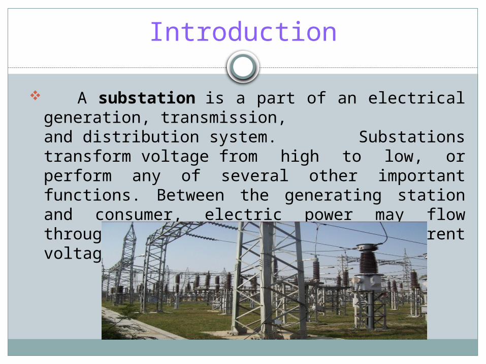
A substation is a part of an electrical generation, transmission, and distribution system. Substations transform voltage from high to low, or perform any of several other important functions. Between the generating station and consumer, electric power may flow through several substations at different voltage levels.
Power Generation And Transmission
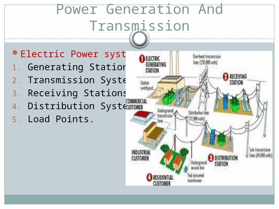
Electric Power system-1. Generating Stations2. Transmission Systems3. Receiving Stations4. Distribution System5. Load Points.
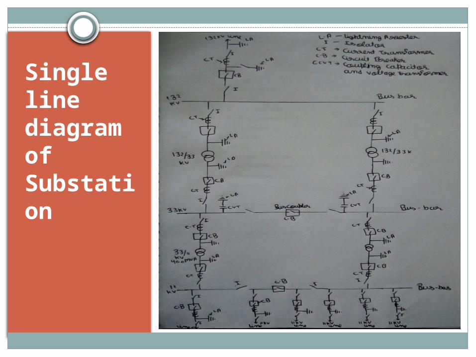
Single line diagram of Substation
Elements of Substation
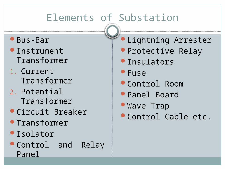
Bus-BarInstrument
Transformer1. Current Transformer2. Potential
TransformerCircuit BreakerTransformerIsolatorControl and Relay
Panel
Lightning ArresterProtective RelayInsulatorsFuseControl RoomPanel BoardWave TrapControl Cable etc.
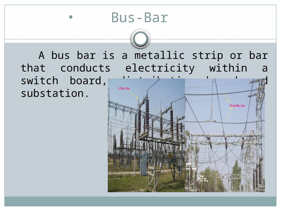
• Bus-Bar
A bus bar is a metallic strip or bar that conducts electricity within a switch board, distribution board and substation.
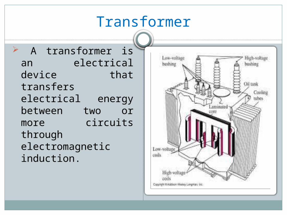
Transformer A transformer is an
electrical device that transfers electrical energy between two or more circuits through electromagnetic induction.
• Instrumentation Transformer
Instrument transformer are high accuracy class electrical devices used to isolate or transform voltage or current levels.
Types of Instrumentation transformer-
1.Current Transformer(C.T.)
2.Potential Transformer(P.T.)
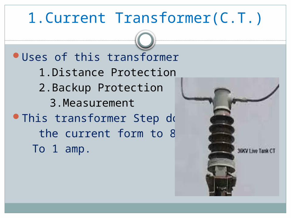
1.Current Transformer(C.T.)
Uses of this transformer 1.Distance Protection 2.Backup Protection 3.Measurement
This transformer Step down the current form to 800 amp. To 1 amp.
2. Potential Transformer(P.T.)
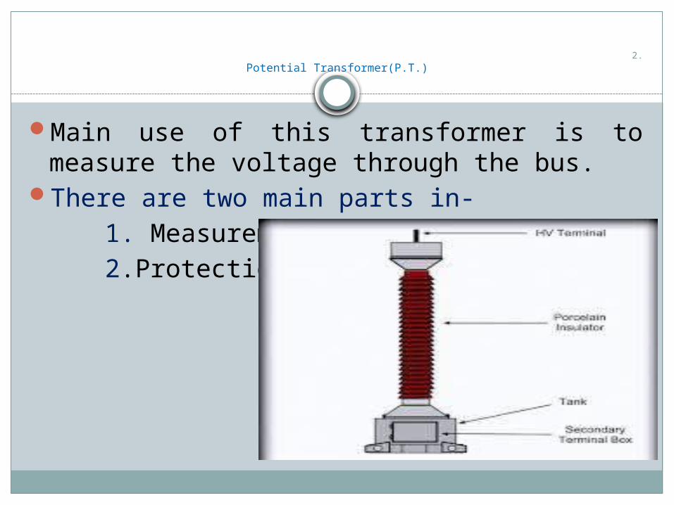
Main use of this transformer is to measure the voltage through the bus.
There are two main parts in- 1. Measurement 2.Protection
• INSULATORS
• Types of insulator 1.Pin type insulator 2.Suspension type insulator 3.Strain type insulator 4. Shackle insulator 5.Stay or Egg insulator
1.Pin type insulator
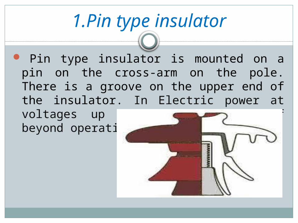
Pin type insulator is mounted on a pin on the cross-arm on the pole. There is a groove on the upper end of the insulator. In Electric power at voltages up to 33 KV and Use of beyond operating voltage of 33 KV.
2.Suspension type insulator
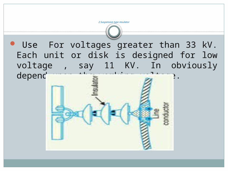
Use For voltages greater than 33 kV. Each unit or disk is designed for low voltage , say 11 KV. In obviously depend upon the working voltage.
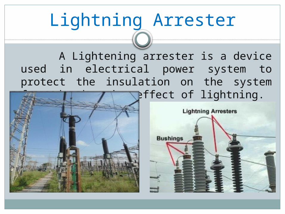
Lightning Arrester
A Lightening arrester is a device used in electrical power system to protect the insulation on the system from the damaging effect of lightning.
Circuit Breaker
Electrical circuit breaker is a switching device which can be operated manually as well as automatically for controlling and protection of electrical power system respectively.
Types of Circuit BreakerI. Air Break Circuit BreakerII. Oil Circuit BreakerIII. Vacuum Circuit Breaker

.
Thank You
All of you