Mohave Hot Gas Defrost Installation & OperationO/H-IM-HGD.pdf · Mohave Hot Gas Defrost...
76
H-IM-HGD0 JUNE 2017 Part Number 25007401 Installation, Start-Up, Operation and Troubleshooting with Wiring Diagrams Mohave Hot Gas Defrost Installation & Operation
Transcript of Mohave Hot Gas Defrost Installation & OperationO/H-IM-HGD.pdf · Mohave Hot Gas Defrost...

H-IM-HGD0 JUNE 2017 Part Number 25007401
Installation, Start-Up, Operation andTroubleshooting with Wiring Diagrams
Mohave Hot Gas Defrost Installation & Operation

2
Controller Quick Reference Guide .............................................................................3-5
Receiving and Inspection
General Safety Information ...................................................................................... 6
Warranty Statement ............................................................................................... 6
System and Components ....................................................................................... 7
Installation
Unit Cooler Installation ............................................................................................ 8
Placement ............................................................................................... 9
Condensate Lines ................................................................................... 10
Condensing Unit Installation
Rigging .............................................................................................. 11
Field Piping Guidelines ........................................................................12-24
Optional Controls ...............................................................................25-26
System Wiring ...................................................................................27-39
Operation
Hot Gas Unit Cooler Typical Factory Piping .............................................................. 40
Hot Gas Condensing Unit Typical Factory Piping ....................................................... 41
Refrigeration Operation ...................................................................................42-43
Defrost Operation ..............................................................................44-47
Evacuation & Leak Detection ................................................................................ 48
Check Out & Start-Up .......................................................................................... 49
Program Review ................................................................................50-51
Monitoring & Reviewing Operation Values ............................................................... 52
Error and Alarm Details......................................................................................... 53
Refrigerant Charging .......................................................................................54-55
Operational Check Out ......................................................................................... 56
Refrigeration Oils .................................................................................... 57
Troubleshooting .................................................................................58-60
Preventive Maintenance ..................................................................................61-62
InterLink Service Parts ......................................................................................... 63
Service Record ...................................................................................... 64
Factory Default Settings ...................................................................................65-68
Mohave Control Board Comparison........................................................................ 69
Electronic Pressure Regulator Comparison .............................................................. 70
Modbus Definitions .........................................................................................71-74
Table of Contents
© 2017, Heatcraft Refrigeration Products LLC

3
Controller Quick Reference Guide
ProgramReview
Clear/Test
ResetTimeMonitorEnter
SelectionKnob
ForceService
ForceDefrost
MODE DESCRIPTIONOFF Compressor Off
COOL Compressor On in Cooling Normal Cooling Operation
PMPD System in Pump Down Mode
SERV Service Mode, System is Off
DELY Time Delay
DEF1 Defrost Stage 1Pre-Defrost or ByPass Mode
DEF2 Defrost Stage 2Defrost Mode
DEF3 Defrost Stage 3Post Defrost Equalization or Drain Down Mode
FREZ Refreeze Mode
TEST Test Mode
SERV Service Mode
EVAC Evacuation Mode
Operating Modes
The Mohave™ Hot Gas Controller is located inside the condensing unit electrical panel. The
Service Switch is adjacent to the controller on the side of the enclosure.
Service Switch
This toggle switch may be placed in the “on” position to force the system into Service Mode. The compressor will pump down and shut off. The evaporator fans will de-energize.
The system can be left in service.
Control Buttons
Program Review: Review or Change the Program Settings
Enter: Accepts changes into memory
Monitor: View Current Operating Conditions of the System
Reset Time: Resets the time clocks of the microprocessor to 0.
Clear/Test: Clear ignores program selections prior to pressing
Enter and terminates Service Mode. Test causes the system to
cycle through all of the outputs for troubleshooting.
Select Knob: Used for Cycling through Monitoring and
Programming Parameters.
Force Service: Press this button twice to cause the system to
pump down and remain off until the Clear button is pressed.
Force Defrost: System will pump down and begin a defrost cycle. This will not effect the normally scheduled defrosts.

4
DISPLAY DESCRIPTION FACTORYDEFAULT
CLKH Set the Time of Day clock hour value NoneCLKM Set the Time of Day clock minute value None°F °C Set Fahrenheit or Celsius temperature units (°F or °C) °F1224 Set Time display method (12 hr. or 24 hr.) 12 hrALRT Set the Alarm Time (2 to 120 minutes) 20 min
RTDF* Defrost Schedule based on Compressor Runtime OFFDF01 Set Defrost 1 starting time (12:00 am to 12:00 pm in 30 minute increments) 12:00AMDF02 Set Defrost 2 starting time 6:00AMDF03 Set Defrost 3 starting time 12:00PMDF04 Set Defrost 4 starting time 6:00PMDF05-DF12 Set Defrost XX starting time --- ---
APPL** Set Application type (Med., Low) Med TempREFR Set Refrigerant type (R-22, R-404A, R-507, R-407A, R-407C, R-407F, R-448A and R-449A)” R-404AMODL Set Model Number 1502XPRT Expert Mode (To Access Additional Program Parameters (On, Off) Off
Program Review Menu
Monitor Display Menu
DISPLAY DESCRIPTIONVALP Defrost Regulator Valve percent of opening (0 to 100%)SUPH Superheat (°F.) measured at inlet of Suction AccumulatorSucT Suction Temperature (°F.) at inlet of Suction AccumulatorSucP Suction Pressure (PSIG/”HG) at inlet of Suction AccumulatorSSuc Saturated Suction Temperature (°F.) at inlet of Suction AccumulatorLIQP Liquid Pressure (PSIG) measured between Receiver and CondenserAMBT Ambient Air Temperature (°F.) measured entering condenser coilAUXT Auxiliary Probe Temperature (°F.)E1DT Evaporator 1 Defrost Sensor Termination Temp (°F.) at outlet of Evaporator 1E2DT Evaporator 2 Defrost Sensor Termination Temp (°F.) at outlet of Evaporator 2ACIN Control Board voltage (24VAC nominal)TMMS Current time minutes and secondsTMHM Current time hours and minutesCCYC Compressor Cycles since MidnightRnTM Compressor Run Time since MidnightDFTM Duration Time of Last DefrostETLD Elapsed Time since last Defrost (HH.MM)RTLD Run Time since last Defrost (HH.MM)VERS Software version
Controller Quick Reference Guide
(See Program Review Section for additional information) *Software V1.04 and higher.**Menu re-ordered Software V2.05 and higher

5
Forced Output Menu
DISPLAY DESCRIPTIONEVPF Evaporator Fan ContactorLIQS Liquid Line SolenoidEVPH Evaporator Pan HeaterFAN4 Condenser Fan 4 ContactorFAN3 Condenser Fan 3 ContactorFAN2 Condenser Fan 2 ContactorFAN1 Condenser Fan 1 ContactorCOMP Compressor ContactorBYPV Bypass SolenoidSucS Suction Stop SolenoidDEFS Defrost Solenoid3WAY 3-Way Valve SolenoidALRM Alarm ContactsVALS Regulator Valve ControlEVAC Activate all Solenoids, Open the Pressure Regulator Valve
DISPLAY DESCRIPTIONAlr1 Persistent input sensor/transducer failureAlr2 Combines Err4 and Err8, system offAlr3 Repeated Safety Circuit Open conditionAlr4 Prolonged Cooling Startup Failure
DISPLAY DESCRIPTIONErr1 Suction temperature sensor open or shortErr2 Ambient temp sensor open or shortErr3 Auxiliary temp sensor open or shortErr4 Suction Pressure sensor open or shortErr5 Liquid Pressure sensor open or shortErr6 Evap 1 defrost temp sensor open or shortErr7 Evap 2 defrost temp sensor open or shortErr8 Redundant Low Pressure Switch Malfunction detectedErr9 Safety Circuit interruption during normal operationEr10 Prolonged Low Suction Pressure during coolingEr11 Low Suction Pressure startup failureEr12 High Suction Pressure startup failureEr13 Post Defrost pump down error
System Alarms
System Errors
Controller Quick Reference Guide

6
General Safety Information1. Installation and maintenance to be performed only by
qualified personnel who are familiar with this type of equipment.
2. Some units are pressurized with dry air or inert gas. All units must be evacuated before charging the system
with refrigerant.
3. Make sure that all field wiring conforms to the requirements of the equipment and all applicable national and local codes.
4. Avoid contact with sharp edges and coil surfaces. They are a potential injury hazard.
5. Make sure all power sources are disconnected before any service work is done on units.
WARNING: Refrigerant can be harmful if it is inhaled. Refrigerant must be used and recovered responsibly. Failure to follow this warning may result in personal injury or death.
InspectionResponsibility should be assigned to a dependable individual at the job site to receive material. Each shipment should be carefully checked against the bill of lading. The shipping receipt should not be signed until all items listed on the bill of lading have been accounted. Check carefully for concealed damage. Any shortage or damages should be reported to the delivering carrier. Damaged material becomes the delivering carrier’s responsibility, and should not be returned to the manufacturer unless prior approval is given to do so. When uncrating, care should be taken to prevent damage. Heavy equipment should be left on its shipping base until it has been moved to the final location. Check the serial tag information with invoice. Report any discrepancies to your Heatcraft Refrigeration Products Sales Representative.
Warranty StatementSeller warrants to its direct purchasers that products, including Service Parts, manufactured by SELLER shall be of a merchantable quality, free of defects in material or workmanship, under normal use and service for a period of one (1) year from date of original installation, or eighteen (18) months from date of shipment by SELLER, whichever first occurs. Any product covered by this order found to Seller’s satisfaction to be defective upon examination at Seller’s factory will at SELLER’s option, be repaired or replaced and returned to Buyer via lowest common carrier, or SELLER may at its option grant Buyer a credit for the purchase price of the defective article. Upon return of a defective product to SELLER’s plant, freight prepaid, by Buyer, correction of such defect by repair or replacement, and return freight via lowest common carrier, shall constitute full performance by SELLER of its obligations hereunder.
SELLER shall have no liability for expenses incurred for repairs made by Buyer except by prior, written authorization. Every claim on account of breach of warranty shall be made to SELLER in writing within the warranty period specified above – otherwise such claim shall be deemed waived. Seller shall have no warranty obligation whatsoever if its products have been subjected to alteration, misuse, negligence, free chemicals in system, corrosive atmosphere, accident, or if operation is contrary to SELLER’s or manufacturer’s recommendations, or if the serial number has been altered, defaced, or removed.
MOTOR COMPRESSORS:Motor compressors furnished by SELLER are subject to the standard warranty terms set forth above, except that motor compressor replacements or exchanges shall be made through the nearest authorized wholesaler of the motor compressor manufacturer (not at SELLER’s factory) and no freight shall be allowed for transportation of the motor compressor to and from the wholesaler. The replacement motor compressor shall be identical to the model of the motor compressor being replaced. Additional charges which may be incurred throughout the substitution of other than identical replacements are not covered by this warranty. An optional, non assignable, four (4) year extended compressor warranty may be purchased within the boundaries of the United Sates of America, its territories and possessions, and Canada. With this extended compressor warranty, replacements are administered by an authorized compressor distributor only. Replacements within the first year of the warranty area available through the distributor; the second through fifth years,
the purchaser must submit a proof-of-purchase of a compressor and supply it to Heatcraft Refrigeration Products Warranty Claims for reimbursement.Seller makes no express warranties except as noted above. All implied warranties are limited to the duration of the Express Warranty. Liability for incidental and consequential damages is excluded.
The forgoing is in lieu of all other warranties, express or implied, notwithstanding the provisions of the uniform commercial code, the Magnuson-Moss Warranty - Federal Trade Commission Improvement Act, or any other statutory or common law, federal or state.
SELLER makes no warranty, express or implied, of fitness for any particular purpose, or of any nature whatsoever, with respect to products manufactures or sold by seller hereunder, except as specifically set forth above and on the face hereof. It is expressly understood and agreed that SELLER shall not be liable to buyer, or any customer of buyer, for direct or indirect, special, incidental, consequential or penal damages, or for any expenses incurred by reason of the use or misuse by buyer or third parties of said products. To the extent said products may be considered "consumer products," As defined in Sec. 101 of the Magnuson-Moss Warranty - Federal Trade Commission Improvement Act, SELLER makes no warranty of any kind, express or implied, to "consumers," except as specifically set forth above and on the face hereof.
The following conditions should be adhered to when installing this unit to maintain the manufacturers warranty:
(a) System piping must be in accordance with good refrigeration practices. (b) Inert gas must be charged into the piping during brazing. (c) The power supply to the unit must meet the following conditions: A. Three phase voltages must be +/- 10% of nameplate ratings. Single phase must be within +10% or -5% of nameplate ratings. B. Phase imbalance cannot exceed 2%.(d) All control and safety switch circuits must be properly connected
according to the wiring diagram. (e) The factory installed wiring must not be changed without written
factory approval.(f) All equipment is installed in accordance with Heatcraft Refrigeration
Products specified minimum clearances.(g) Devices not provided by Heatcraft shall not be connected to the
Mohave controller without written factory approval(h) Refrigerant line runs between condensing unit and evaporator(s) shall
not exceed 200 ft without written factory approval
7
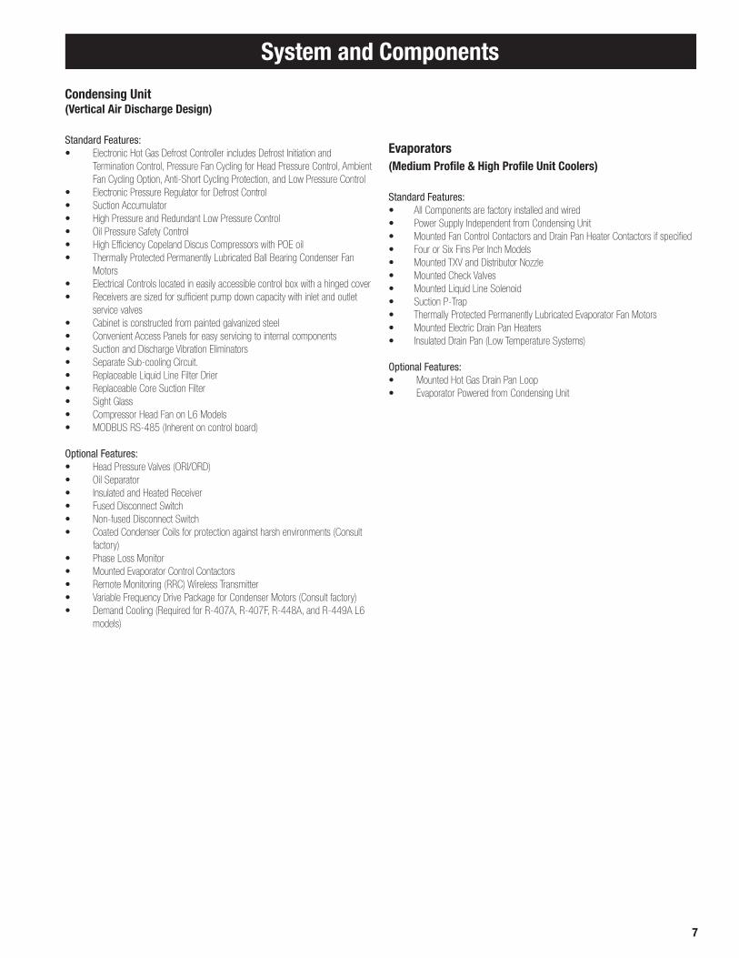
Condensing Unit(Vertical Air Discharge Design)
Standard Features:• Electronic Hot Gas Defrost Controller includes Defrost Initiation and
Termination Control, Pressure Fan Cycling for Head Pressure Control, Ambient Fan Cycling Option, Anti-Short Cycling Protection, and Low Pressure Control
• Electronic Pressure Regulator for Defrost Control• Suction Accumulator• High Pressure and Redundant Low Pressure Control• Oil Pressure Safety Control• High Efficiency Copeland Discus Compressors with POE oil• Thermally Protected Permanently Lubricated Ball Bearing Condenser Fan
Motors• Electrical Controls located in easily accessible control box with a hinged cover• Receivers are sized for sufficient pump down capacity with inlet and outlet
service valves• Cabinet is constructed from painted galvanized steel• Convenient Access Panels for easy servicing to internal components• Suction and Discharge Vibration Eliminators• Separate Sub-cooling Circuit.• Replaceable Liquid Line Filter Drier• Replaceable Core Suction Filter• Sight Glass• Compressor Head Fan on L6 Models• MODBUS RS-485 (Inherent on control board)
Optional Features:• Head Pressure Valves (ORI/ORD)• Oil Separator• Insulated and Heated Receiver• Fused Disconnect Switch• Non-fused Disconnect Switch• Coated Condenser Coils for protection against harsh environments (Consult
factory)• Phase Loss Monitor• Mounted Evaporator Control Contactors• Remote Monitoring (RRC) Wireless Transmitter• Variable Frequency Drive Package for Condenser Motors (Consult factory)• Demand Cooling (Required for R-407A, R-407F, R-448A, and R-449A L6 models)
Evaporators (Medium Profile & High Profile Unit Coolers)
Standard Features:• All Components are factory installed and wired• Power Supply Independent from Condensing Unit• Mounted Fan Control Contactors and Drain Pan Heater Contactors if specified• Four or Six Fins Per Inch Models• Mounted TXV and Distributor Nozzle• Mounted Check Valves• Mounted Liquid Line Solenoid• Suction P-Trap• Thermally Protected Permanently Lubricated Evaporator Fan Motors• Mounted Electric Drain Pan Heaters• Insulated Drain Pan (Low Temperature Systems)
Optional Features:• Mounted Hot Gas Drain Pan Loop • Evaporator Powered from Condensing Unit
System and Components

8
top and the ceiling with an NSF listed sealant and ends of open hanger channels must be sealed to prevent accumulation of foreign matter.
When locating unit coolers in a cooler or freezer, refer to Figure 1-2 for guidelines.
Unit Cooler InstallationMost evaporators can be mounted with rod hangers, lag screws, or bolts. Use 5/16" bolt and washers or rod for up to 250 pounds, 3/8" for up to 600 pounds and 5/8" for over 600 pounds. Care should be taken to mount the units level so that condensate drains properly. Adequate support must be provided to hold the weight of the unit.
When using rod hangers, allow adequate space between the top of the unit and the ceiling for cleaning. To comply with NSF Standard 7, the area above the unit cooler must be sealed or exposed in such a way to facilitate hand cleaning without the use of tools. When lagging or bolting the unit flush to the ceiling, seal the joint between the
Figure 1. Large Coolers and Freezers Placement.
Where one wall evaporator mounting is satisfactory.
Elevation view of glass display door cooler or freezer. Be sure air discharge blows above, not directly at doors. Provide baffle if door extends above blower level.
Baffled Unit
Cooler or Freezer with Glass Display Doors
GlassDisplayDoor
Baffle
NOTE: Always avoid placement of Unit Coolersdirectly above doors and door openings.
Cooler or Freezers where one wall will not accommodate all required evaporators or where air throw distance must be considered.
Allow sufficient space between rear of Unit Cooler and wall to permit free return of air.
Unit Cooler Installation

9
One evaporator
Unit Coolers (continued)
Recommended Unit Cooler PlacementSome general rules for evaporator placement which must be followed are:
1. The air pattern must cover the entire room2. NEVER locate evaporators over doors3. Location of aisles, racks, etc. must be known4. Location relative to compressors for minimum pipe runs5. Location of condensate drains for minimum run.
The size and shape of the storage will generally determine the type and number of evaporators to be used and their location. The following are some typical examples:
Minimum Unit Clearances
Figure 2. Medium Profile and Large Unit Coolers
NOTE: W = Total width of evaporator coil surface.
Two evaporators
Unit Cooler Installation & Condensate Lines
WARNING: All power must be disconnected before cleaning. Drain pan also serves as cover of hazardous moving parts. Operation of unit without drain pan constitutes a hazard.
Condensate Drain LinesEither copper or steel drain lines should be used and properly protected from freezing. In running drain lines, provide a minimum 4 inches per foot pitch for proper drainage. Drain lines should be at least as large as the evaporator drain connection. All plumbing connections should be made in accordance with local plumbing codes. All condensate drain lines must be trapped, and run to an open drain. They must never be connected directly to the sewer system. Traps in the drain line must be located in a warm ambient. We recommend a trap on each evaporator drain line prior to any tee connections. Traps located outside, or extensive outside runs of drain line must be wrapped with a drain line heater. The heater should be connected so that it operates continuously. It is recommended that the drain line be insulated to prevent heat loss. A heat input of 20 watts per linear foot of drain line for 0˚F (-18˚C) room applications and 30 watts per linear foot for -20˚F (-29˚C) rooms is satisfactory. In freezers, the evaporator drain pan fitting should be included when heating and insulating the drain line.
Inspect drain pan periodically to insure free drainage of condensate. If drain pan contains standing water, check for proper installation. The drain pan should be cleaned regularly with warm soapy water.
Condensate Drain Lines
NOTE: Always trap single evaporator system drain lines individually to prevent humidity migration.
Traps on low temperature units must be outside of refrigerated enclosures. Traps subject to freezing temperatures must be wrapped with heat tape and insulated.
NOTE: Leave space equal to unit height between bottom of unit and product. Do not stack product in front of fans.
- 1/4” / FT
10
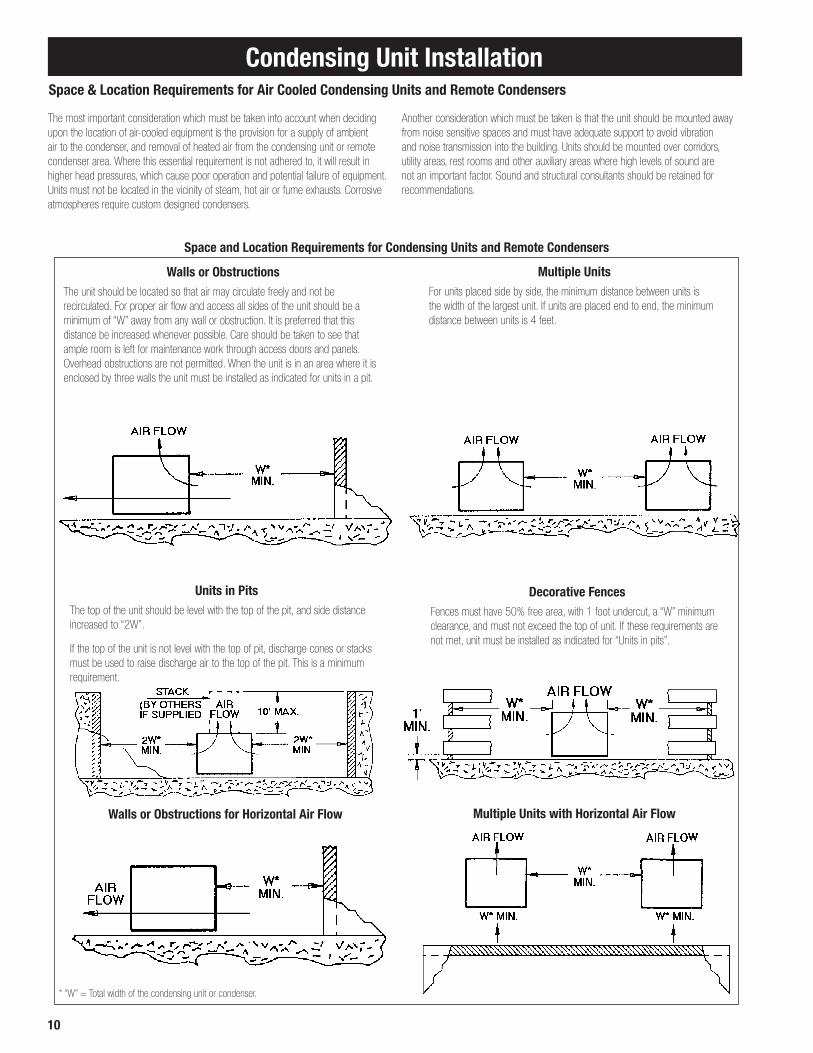
The most important consideration which must be taken into account when deciding upon the location of air-cooled equipment is the provision for a supply of ambient air to the condenser, and removal of heated air from the condensing unit or remote condenser area. Where this essential requirement is not adhered to, it will result in higher head pressures, which cause poor operation and potential failure of equipment. Units must not be located in the vicinity of steam, hot air or fume exhausts. Corrosive atmospheres require custom designed condensers.
Another consideration which must be taken is that the unit should be mounted away from noise sensitive spaces and must have adequate support to avoid vibration and noise transmission into the building. Units should be mounted over corridors, utility areas, rest rooms and other auxiliary areas where high levels of sound are not an important factor. Sound and structural consultants should be retained for recommendations.
Space and Location Requirements for Condensing Units and Remote Condensers
Units in PitsThe top of the unit should be level with the top of the pit, and side distance increased to “2W”.
If the top of the unit is not level with the top of pit, discharge cones or stacks must be used to raise discharge air to the top of the pit. This is a minimum requirement.
Decorative FencesFences must have 50% free area, with 1 foot undercut, a “W” minimum clearance, and must not exceed the top of unit. If these requirements are not met, unit must be installed as indicated for “Units in pits”.
Walls or ObstructionsThe unit should be located so that air may circulate freely and not be recirculated. For proper air flow and access all sides of the unit should be a minimum of “W” away from any wall or obstruction. It is preferred that this distance be increased whenever possible. Care should be taken to see that ample room is left for maintenance work through access doors and panels. Overhead obstructions are not permitted. When the unit is in an area where it is enclosed by three walls the unit must be installed as indicated for units in a pit.
Multiple UnitsFor units placed side by side, the minimum distance between units is the width of the largest unit. If units are placed end to end, the minimum distance between units is 4 feet.
Walls or Obstructions for Horizontal Air Flow Multiple Units with Horizontal Air Flow
* “W” = Total width of the condensing unit or condenser.
Space & Location Requirements for Air Cooled Condensing Units and Remote Condensers
Condensing Unit Installation

11
Figure 3. Spring Mount
Figure 5. Spring Mount
Figure 4. Solid Mount for Mobile or Deep Sump Application.
Condensing Unit Rigging and MountingRigging holes are provided on all units. Caution should be exercised when moving these units. To prevent damage to the unit housing during rigging, cables or chains used must be held apart by spacer bars. The mounting platform or base should be level and located so as to permit free access of supply air.
Ground MountingConcrete slab raised six inches above ground level provides a suitable base. Raising the base above ground level provides some protection from ground water and wind blown matter. Before tightening mounting bolts, recheck level of unit. The unit should in all cases be located with a clear space in all directions that is at a minimum, equal to the height of the unit above the mounting surface. A condensing unit mounted in a corner formed by two walls, may result in discharge air recirculation with resulting loss of capacity.
Roof MountingDue to the weight of the units, a structural analysis by a qualified engineer may be required before mounting. Roof mounted units should be installed level on steel channels or an I-beam frame capable of supporting the weight of the unit. Vibration absorbing pads or springs should be installed between the condensing unit legs or frame and the roof mounting assembly.
AccessProvide adequate space at the compressor end of the unit for servicing. Provide adequate space on the connection side to permit service of components.
Spring Mounted CompressorCompressors are secured rigidly to make sure there is no transit damage. Before operating the unit, it is necessary to follow these steps:
a. Remove the upper nuts and washers.b. Discard the shipping spacers.c. Install the neoprene spacers. (Spacers located in the electrical panel or
tied to compressor.)d. Replace the upper mounting nuts and washers.e. Allow 1/16 inch space between the mounting nut/
washer and the neoprene spacer. See Figure 3 below.
Rigid Mounted CompressorSome products use rigid mounted compressors. Check the compressor mounting bolts to insure they have not vibrated loose during shipment. See Figure 3 and 5 below.
Condensing Unit Installation

12
Recommended Refrigerant Piping PracticesThe system as supplied by Heatcraft Refrigeration Products, was thoroughly cleaned and dehydrated at the factory. Foreign matter may enter the system by way of the evaporator to condensing unit piping. Therefore, care must be used during installation of the piping to prevent entrance of foreign matter.
Install all refrigeration system components in accordance with applicable local and national codes and in conformance with good practice required for the proper operation of the system.
The refrigerant pipe size should be selected from the tables on pages 15-21. The interconnecting pipe size is not necessarily the same size as the stub-out on the condensing unit or the evaporator.
The following procedures should be followed:(a) Do not leave dehydrated compressors or filter driers open to the
atmosphere.(b) Use only refrigeration grade copper tubing, properly sealed against
contamination. (c) Suction lines should slope 1/4" per 10 feet towards the compressor.(d) Suitable P-type oil traps should be located at the base of each
suction riser to enhance oil return to the compressor.(e) For desired method of superheat measurement, a pressure tap
should be installed in each evaporator suction line in the proximity of the expansion valve bulb.
(f) When brazing refrigerant lines, an inert gas should be passed through the line at low pressure to prevent scaling and oxidation inside the tubing. Dry nitrogen is preferred.
(g) Use only a suitable silver solder alloy on suction and liquid lines.(h) Limit the soldering paste or flux to the minimum required to prevent
contamination of the solder joint internally. Flux only the male portion of the connection, never the female. After brazing, remove excess flux.
(i) If isolation valves are installed at the evaporator,full port ball valves should be used.
(j) Do not install liquid/suction line heat exchangers.
Refrigerant Pipe Support1. Normally, any straight run of tubing must be supported in at least two locations
near each end of the run. Long runs require additional supports. The refrigerant lines should be supported and fastened properly. As a guide, 3/8 to 7/8 should be supported every 5 feet; 1-1/8 and 1-3/8 every 7 feet; and 1-5/8 and 2-1/8 every 9 to 10 feet.
2. When changing directions in a run of tubing, no corner should be left unsupported. Supports should be placed a maximum of 2 feet in each direction from the corner.
3. Piping attached to a vibrating object (such as a compressor or compressor base) must be supported in such a manner that will not restrict the movement of the vibrating object. Rigid mounting will fatigue the copper tubing.
4. Do not use short radius ells. Short radius elbows have points of excessive stress concentration and are subject to breakage at these points.
5. Thoroughly inspect all piping after the equipment is in operation and add supports wherever line vibration is significantly greater than most of the other piping. Extra supports are relatively inexpensive as compared to refrigerant loss.
Piping
Example of Pipe Support Condensing Unit / Compressor to Wall Support.
13
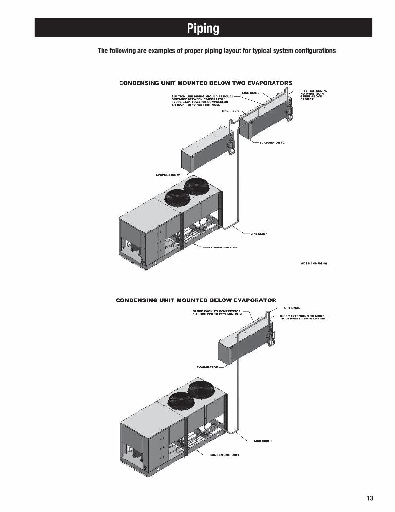
Piping
The following are examples of proper piping layout for typical system configurations

14
Piping

15
Pipe size example:Given: -10°F Freezer with one system having (2) evaporators
• One condensing unit rated at 24,000 BTUH’s @ -20°F SST R404A refrigerant.
• Two evaporators each rated at 12,000 BTUH’s @ 10°F TD.
• 75 feet of actual line run between condensing unit to first evaporator and 20 feet of actual line run between the first evaporator and the second evaporator (see figure below).
How to figure line sizes:1. Determine equivalent line run = actual run + valves and fitting allowances.
2. Use Line Sizing Tables on pages 16-21 to size lines.
3. Note any special considerations.
Fittings in this system:• (6) 90° elbows in main line plus a 90° turn through a tee.
• (5) addtional 90° elbows to first evaporator.
• (4) additional 90° elbows to second evaporator.
Determine line size 1 (main line from condensing unit):1. Main line from the condensing unit to be sized for the total capacity (balance) of
the whole system of 24,000 BTUH’s (Table 3 and 3A).
2. Refer to 24,000 @75 feet at -20°F SST R404A on the chart. You will find the suction line to be 1 1/8" and 1/2" liquid line.
3. Refer to Table 5A. For every 1 1/8" 90° elbow you must add 3 equivalent feet of pipe and 2 equivalent feet of pipe for each 1 1/8" tee.
Therefore, total equivalent line run =
Actual line run 75 feet
+ (6) 1 1/8" elbows @ 3' 18 feet
+ (1) 1 1/8" tee @ 2' 2 feet
Total equivalent line run 95 feet
4. Refer to Table 3A. For 95 total equivalent feet, the suction line size should be 1 3/8" and the liquid line stays at 1/2" line.
Note: The gray shaded areas on Table 2. For 24,000 BTUH’s, the maximum suction riser is 1 1/8" to insure proper oil return and pressure drop from the bottom p-trap to the top p-trap.
Determine line size 2 (evaporators):1. Line sizing to each evaporator is based on 12,000 BTUH’s and equivalent
run from condensing unit. First evaporator has an 80 ft. run and the second evaporator has a 95 ft. run.
2. Table 3 indicates 7/8" suction for the first evaporator and Table 3A indicates 1 1/8" suction for the second evaporator.
3. Refer to Table 5A. Each 7/8" 90° elbow adds 2 equivalent feet of pipe. Each 1 1/8" 90° elbow adds 3 equivalent feet and a 90° turn through a 1 1/8" tee adds 6 equivalent feet.
4. Actual line run (evap 1) 80 feet
+ (5) 7/8" elbows @ 2' 10 feet
+ (1) 90° turn through tee @ 6' 6 feet
Total equivalent line run 96 feet
Actual line run (evap 2) 95 feet
+ (4) 1 1/8" elbows @ 3' 12 feet
Total equivalent line run 107 feet
5. Table 3A indicates 1 1/8" suction line and 3/8" liquid line from main line to both evaporators.
Unit Cooler Piping
Evap. 1Evap. 2
Piping
NOTE: This is a line sizing example. Use diagrams on page 13-14 for piping orientation.

16
SystemCapacity
+40 ˚FEquivalent Lengths
+20 ˚FEquivalent Lengths
+10 ˚FEquivalent Lengths
25' 50' 75' 100' 150' 200' 25' 50' 75' 100' 150' 200' 25' 50' 75' 100' 150' 200'
1,000 3/8 3/8 3/8 3/8 3/8 3/8 3/8 3/8 3/8 3/8 3/8 3/8 3/8 3/8 3/8 3/8 3/8 3/8
3,000 3/8 3/8 3/8 3/8 1/2 1/2 3/8 3/8 3/8 1/2 1/2 1/2 3/8 3/8 1/2 1/2 1/2 1/2
4,000 3/8 3/8 1/2 1/2 1/2 1/2 3/8 1/2 1/2 1/2 5/8 5/8 3/8 1/2 1/2 5/8 5/8 5/8
6,000 3/8 1/2 1/2 1/2 5/8 5/8 1/2 1/2 1/2 5/8 5/8 5/8 1/2 1/2 5/8 5/8 5/8 5/8
9,000 1/2 1/2 5/8 5/8 5/8 5/8 1/2 5/8 5/8 7/8 7/8 7/8 1/2 5/8 5/8 7/8 7/8 7/8
12,000 1/2 5/8 5/8 7/8 7/8 7/8 5/8 5/8 7/8 7/8 7/8 7/8 5/8 7/8 7/8 7/8 7/8 7/8
15,000 5/8 5/8 7/8 7/8 7/8 7/8 5/8 7/8 7/8 7/8 7/8 7/8 5/8 7/8 7/8 7/8 7/8 7/8
18,000 5/8 7/8 7/8 7/8 7/8 7/8 5/8 7/8 7/8 7/8 7/8 7/8 7/8 7/8 7/8 7/8 1 1/8 1 1/8
24,000 5/8 7/8 7/8 7/8 7/8 7/8 7/8 7/8 7/8 7/8 1 1/8 1 1/8 7/8 7/8 7/8 1 1/8 1 1/8 1 1/8
30,000 7/8 7/8 7/8 7/8 1 1/8 1 1/8 7/8 7/8 7/8 1 1/8 1 1/8 1 1/8 7/8 7/8 1 1/8 1 1/8 1 1/8 1 1/8
36,000 7/8 7/8 7/8 1 1/8 1 1/8 1 1/8 7/8 7/8 1 1/8 1 1/8 1 1/8 1 1/8 7/8 1 1/8 1 1/8 1 1/8 1 1/8 1 3/8
42,000 7/8 7/8 1 1/8 1 1/8 1 1/8 1 1/8 7/8 7/8 1 1/8 1 1/8 1 1/8 1 1/8 7/8 1 1/8 1 1/8 1 1/8 1 3/8 1 3/8
48,000 7/8 7/8 1 1/8 1 1/8 1 1/8 1 1/8 7/8 1 1/8 1 1/8 1 1/8 1 3/8 1 3/8 7/8 1 1/8 1 1/8 1 1/8 1 3/8 1 3/8
54,000 7/8 1 1/8 1 1/8 1 1/8 1 1/8 1 3/8 7/8 1 1/8 1 1/8 1 1/8 1 3/8 1 3/8 1 1/8 1 1/8 1 1/8 1 3/8 1 3/8 1 3/8
60,000 7/8 1 1/8 1 1/8 1 1/8 1 3/8 1 3/8 1 1/8 1 1/8 1 1/8 1 3/8 1 3/8 1 3/8 1 1/8 1 1/8 1 1/8 1 3/8 1 3/8 1 3/8
66,000 7/8 1 1/8 1 1/8 1 1/8 1 3/8 1 3/8 1 1/8 1 1/8 1 1/8 1 3/8 1 3/8 1 3/8 1 1/8 1 1/8 1 3/8 1 3/8 1 3/8 1 5/8
72,000 7/8 1 1/8 1 1/8 1 1/8 1 3/8 1 3/8 1 1/8 1 1/8 1 1/8 1 3/8 1 3/8 1 3/8 1 1/8 1 1/8 1 3/8 1 3/8 1 3/8 1 5/8
78,000 7/8 1 1/8 1 1/8 1 3/8 1 3/8 1 3/8 1 1/8 1 1/8 1 1/8 1 3/8 1 3/8 1 5/8 1 1/8 1 1/8 1 3/8 1 3/8 1 5/8 1 5/8
84,000 1 1/8 1 1/8 1 1/8 1 3/8 1 3/8 1 3/8 1 1/8 1 1/8 1 3/8 1 3/8 1 5/8 1 5/8 1 1/8 1 3/8 1 3/8 1 3/8 1 5/8 1 5/8
90,000 1 1/8 1 1/8 1 3/8 1 3/8 1 3/8 1 5/8 1 1/8 1 3/8 1 3/8 1 5/8 1 5/8 1 5/8 1 1/8 1 3/8 1 3/8 1 5/8 1 5/8 1 5/8
120,000 1 1/8 1 3/8 1 3/8 1 5/8 1 5/8 1 5/8 1 3/8 1 3/8 1 5/8 1 5/8 1 5/8 2 1/8 1 3/8 1 5/8 1 5/8 1 5/8 2 1/8 2 1/8
150,000 1 3/8 1 3/8 1 5/8 1 5/8 1 5/8 2 1/8 1 3/8 1 5/8 1 5/8 1 5/8 2 1/8 2 1/8 1 3/8 1 5/8 1 5/8 2 1/8 2 1/8 2 1/8
180,000 1 3/8 1 3/8 1 5/8 1 5/8 2 1/8 2 1/8 1 3/8 1 5/8 1 5/8 2 1/8 2 1/8 2 1/8 1 5/8 2 1/8 2 1/8 2 1/8 2 1/8 2 1/8
210,000 1 3/8 1 5/8 1 5/8 2 1/8 2 1/8 2 1/8 1 5/8 1 5/8 2 1/8 2 1/8 2 1/8 2 1/8 1 5/8 2 1/8 2 1/8 2 1/8 2 1/8 2 5/8
240,000 1 5/8 1 5/8 2 1/8 2 1/8 2 1/8 2 1/8 1 5/8 2 1/8 2 1/8 2 1/8 2 1/8 2 5/8 1 5/8 2 1/8 2 1/8 2 1/8 2 5/8 2 5/8
300,000 1 5/8 2 1/8 2 1/8 2 1/8 2 1/8 2 5/8 1 5/8 2 1/8 2 1/8 2 1/8 2 5/8 2 5/8 2 1/8 2 1/8 2 1/8 2 5/8 2 5/8 2 5/8
360,000 1 5/8 2 1/8 2 1/8 2 1/8 2 5/8 2 5/8 2 1/8 2 1/8 2 1/8 2 5/8 2 5/8 2 5/8 2 1/8 2 1/8 2 5/8 2 5/8 2 5/8 2 5/8
480,000 2 1/8 2 1/8 2 1/8 2 5/8 2 5/8 2 5/8 2 1/8 2 5/8 2 5/8 2 5/8 3 1/8 3 1/8 2 1/8 2 5/8 2 5/8 3 1/8 3 1/8 3 1/8
600,000 2 1/8 2 5/8 2 5/8 2 5/8 3 1/8 3 1/8 2 5/8 2 5/8 2 5/8 3 1/8 3 1/8 3 1/8 2 1/8 2 5/8 3 1/8 3 1/8 3 1/8 3 5/8
Table 1. Recommended Line Sizes for R-407*
* NOTES: 1. Sizes that are highlighted indicate maximum suction line sizes that should be used for risers. Riser size should not exceed horizontal size. Properly placed suction traps must also be used for
adequate oil return. All sizes shown are for O.D. Type L copper tubing. 2. Suction line sizes selected at pressure drop equivalent to 2˚F. Reduce estimate of system capacity accordingly. 3. If system load drops below 40% of design, consideration to installing double suction risers should be made. 4. R407A, R407C, R407F
Line Sizing
SUCTION LINE SIZE
SUCTION TEMPERATURE

17
Line Sizing
Table 1A. Recommended Line Sizes for R-407 (continued)*
LIQUID LINE SIZE
Receiver to Expansion Valve
Expansion Valve
25' 50' 75' 100' 150' 200'
3/8 3/8 3/8 3/8 3/8 3/8 1,000
3/8 3/8 3/8 3/8 3/8 3/8 3,000
3/8 3/8 3/8 3/8 3/8 3/8 4,000
3/8 3/8 3/8 3/8 3/8 3/8 6,000
3/8 3/8 3/8 3/8 3/8 3/8 9,000
3/8 3/8 3/8 3/8 3/8 3/8 12,000
3/8 3/8 3/8 3/8 3/8 3/8 15,000
3/8 3/8 3/8 3/8 1/2 1/2 18,000
3/8 3/8 3/8 1/2 1/2 1/2 24,000
3/8 1/2 1/2 1/2 1/2 5/8 30,000
3/8 1/2 1/2 1/2 5/8 5/8 36,000
3/8 1/2 1/2 1/2 5/8 5/8 42,000
1/2 1/2 1/2 5/8 5/8 5/8 48,000
1/2 1/2 1/2 5/8 5/8 5/8 54,000
1/2 1/2 5/8 5/8 5/8 5/8 60,000
1/2 1/2 5/8 5/8 5/8 7/8 66,000
1/2 5/8 5/8 5/8 5/8 7/8 72,000
1/2 5/8 5/8 5/8 7/8 7/8 78,000
1/2 5/8 5/8 5/8 7/8 7/8 84,000
1/2 5/8 5/8 7/8 7/8 7/8 90,000
5/8 5/8 7/8 7/8 7/8 7/8 120,000
5/8 7/8 7/8 7/8 7/8 7/8 150,000
7/8 7/8 7/8 7/8 1 1/8 1 1/8 180,000
7/8 7/8 7/8 7/8 1 1/8 1 1/8 210,000
7/8 7/8 7/8 1 1/8 1 1/8 1 1/8 240,000
7/8 7/8 7/8 1 1/8 1 1/8 1 1/8 300,000
7/8 1 1/8 1 1/8 1 1/8 1 1/8 1 3/8 360,000
7/8 1 1/8 1 1/8 1 3/8 1 3/8 1 3/8 480,000
1 1/8 1 1/8 1 3/8 1 3/8 1 3/8 1 3/8 600,000
* NOTES: 1. All sizes shown are for O.D. Type L copper tubing. 2 .R407A, 407C, R407F

18
* NOTES: 1. Sizes that are highlighted indicate maximum suction line sizes that should be used for risers. Riser size should not exceed horizontal size. Properly placed suction traps must also be used for
adequate oil return. All sizes shown are for O.D. Type L copper tubing. 2. Suction line sizes selected at pressure drop equivalent to 2˚F. Reduce estimate of system capacity accordingly. 3. If system load drops below 40% of design, consideration to installing double suction risers should be made. 4. R407A, R407C, R407F
Line Sizing
Add R448A/R449A line sizing ta-bles. See file named 448 449 final
SystemCapacityBTU/H
SUCTION LINE SIZE
SUCTION TEMPERATURE
+20 ˚FEquivalent Lengths
+10 ˚FEquivalent Lengths
-10 ˚FEquivalent Lengths
25' 50' 75' 100' 150' 200' 25' 50' 75' 100' 150' 200' 25' 50' 75' 100' 150' 200'
1,000 3/8 3/8 3/8 3/8 3/8 3/8 3/8 3/8 3/8 3/8 3/8 1/2 3/8 3/8 3/8 1/2 1/2 1/2
3,000 3/8 3/8 1/2 1/2 1/2 5/8 3/8 1/2 1/2 1/2 5/8 5/8 1/2 1/2 5/8 5/8 5/8 7/8
4,000 3/8 1/2 1/2 1/2 5/8 5/8 1/2 1/2 1/2 5/8 5/8 7/8 1/2 5/8 5/8 5/8 7/8 7/8
6,000 1/2 1/2 5/8 5/8 7/8 7/8 1/2 1/2 5/8 5/8 7/8 7/8 1/2 5/8 5/8 7/8 7/8 7/8
9,000 5/8 5/8 7/8 7/8 7/8 7/8 5/8 5/8 7/8 7/8 7/8 7/8 5/8 7/8 7/8 7/8 7/8 1 1/8
12,000 5/8 7/8 7/8 7/8 7/8 7/8 5/8 7/8 7/8 7/8 7/8 1 1/8 7/8 7/8 7/8 7/8 1 1/8 1 1/8
15,000 5/8 7/8 7/8 7/8 7/8 1 1/8 7/8 7/8 7/8 7/8 1 1/8 1 1/8 7/8 7/8 7/8 1 1/8 1 1/8 1 1/8
18,000 7/8 7/8 7/8 7/8 1 1/8 1 1/8 7/8 7/8 7/8 1 1/8 1 1/8 1 1/8 7/8 7/8 1 1/8 1 1/8 1 1/8 1 3/8
24,000 7/8 7/8 7/8 1 1/8 1 1/8 1 1/8 7/8 1 1/8 1 1/8 1 1/8 1 1/8 1 3/8 7/8 1 1/8 1 1/8 1 1/8 1 3/8 1 3/8
30,000 7/8 7/8 1 1/8 1 1/8 1 1/8 1 3/8 7/8 1 1/8 1 1/8 1 1/8 1 3/8 1 3/8 1 1/8 1 1/8 1 1/8 1 3/8 1 3/8 1 3/8
36,000 7/8 1 1/8 1 1/8 1 1/8 1 3/8 1 3/8 1 1/8 1 1/8 1 1/8 1 3/8 1 3/8 1 3/8 1 1/8 1 1/8 1 3/8 1 3/8 1 3/8 1 5/8
42,000 1 1/8 1 1/8 1 1/8 1 3/8 1 3/8 1 3/8 1 1/8 1 1/8 1 3/8 1 3/8 1 3/8 1 5/8 1 1/8 1 3/8 1 3/8 1 3/8 1 5/8 1 5/8
48,000 1 1/8 1 1/8 1 3/8 1 3/8 1 3/8 1 3/8 1 1/8 1 1/8 1 3/8 1 3/8 1 5/8 1 5/8 1 1/8 1 3/8 1 3/8 1 3/8 1 5/8 1 5/8
54,000 1 1/8 1 1/8 1 3/8 1 3/8 1 3/8 1 5/8 1 1/8 1 3/8 1 3/8 1 3/8 1 5/8 1 5/8 1 3/8 1 3/8 1 3/8 1 5/8 1 5/8 1 5/8
60,000 1 1/8 1 1/8 1 3/8 1 3/8 1 5/8 1 5/8 1 1/8 1 3/8 1 3/8 1 5/8 1 5/8 1 5/8 1 3/8 1 3/8 1 5/8 1 5/8 1 5/8 2 1/8
66,000 1 1/8 1 3/8 1 3/8 1 3/8 1 5/8 1 5/8 1 1/8 1 3/8 1 3/8 1 5/8 1 5/8 1 5/8 1 3/8 1 5/8 1 5/8 1 5/8 1 5/8 1 5/8
72,000 1 1/8 1 3/8 1 3/8 1 5/8 1 5/8 1 5/8 1 1/8 1 3/8 1 5/8 1 5/8 1 5/8 1 5/8 1 3/8 1 5/8 1 5/8 1 5/8 1 5/8 1 5/8
78,000 1 1/8 1 3/8 1 3/8 1 5/8 1 5/8 2 1/8 1 3/8 1 3/8 1 5/8 1 5/8 1 5/8 2 1/8 1 3/8 1 5/8 1 5/8 1 5/8 1 5/8 2 1/8
84,000 1 1/8 1 3/8 1 5/8 1 5/8 1 5/8 2 1/8 1 3/8 1 3/8 1 5/8 1 5/8 2 1/8 2 1/8 1 3/8 1 5/8 1 5/8 1 5/8 2 1/8 2 1/8
90,000 1 3/8 1 3/8 1 5/8 1 5/8 2 1/8 2 1/8 1 3/8 1 5/8 1 5/8 1 5/8 2 1/8 2 1/8 1 5/8 1 5/8 1 5/8 2 1/8 2 1/8 2 5/8
120,000 1 3/8 1 5/8 1 5/8 2 1/8 2 1/8 2 1/8 1 3/8 1 5/8 2 1/8 2 1/8 2 1/8 2 1/8 1 5/8 2 1/8 2 1/8 2 1/8 2 5/8 2 5/8
150,000 1 5/8 1 5/8 2 1/8 2 1/8 2 1/8 2 1/8 1 5/8 2 1/8 2 1/8 2 1/8 2 1/8 2 5/8 2 1/8 2 1/8 2 1/8 2 5/8 2 5/8 2 5/8
180,000 1 5/8 2 1/8 2 1/8 2 1/8 2 1/8 2 5/8 1 5/8 2 1/8 2 1/8 2 1/8 2 5/8 2 5/8 2 1/8 2 1/8 2 5/8 2 5/8 2 5/8 3 1/8
210,000 1 5/8 2 1/8 2 1/8 2 1/8 2 5/8 2 5/8 2 1/8 2 1/8 2 1/8 2 5/8 2 5/8 2 5/8 2 1/8 2 1/8 2 5/8 2 5/8 3 1/8 3 1/8
240,000 1 5/8 2 1/8 2 1/8 2 1/8 2 5/8 2 5/8 2 1/8 2 1/8 2 5/8 2 5/8 2 5/8 2 5/8 2 1/8 2 5/8 2 5/8 2 5/8 3 1/8 3 1/8
300,000 2 1/8 2 1/8 2 5/8 2 5/8 2 5/8 3 1/8 2 1/8 2 5/8 2 5/8 2 5/8 3 1/8 3 1/8 2 5/8 2 5/8 2 5/8 3 1/8 3 1/8 3 5/8
360,000 2 1/8 2 1/8 2 5/8 2 5/8 3 1/8 3 1/8 2 1/8 2 5/8 2 5/8 2 5/8 3 1/8 3 1/8 2 5/8 2 5/8 3 1/8 3 1/8 3 5/8 3 5/8
480,000 2 1/8 2 5/8 2 5/8 3 1/8 3 1/8 3 5/8 2 5/8 2 5/8 2 5/8 2 5/8 3 5/8 3 5/8 2 5/8 3 1/8 3 1/8 3 5/8 3 5/8 4 1/8
600,000 2 5/8 2 5/8 3 1/8 3 1/8 3 5/8 3 5/8 2 5/8 2 5/8 3 1/8 3 1/8 3 5/8 3 5/8 3 1/8 3 1/8 3 1/8 3 5/8 4 1/8 4 1/8
Table 2. Recommended Line Sizes for R-448A/R-449A

19
Line Sizing
SystemCapacityBTU/H
SUCTION LINE SIZE
SUCTION TEMPERATURE
-20 ˚FEquivalent Lengths
-30 ˚FEquivalent Lengths
-40 ˚FEquivalent Lengths
25' 50' 75' 100' 150' 200' 25' 50' 75' 100' 150' 200' 25' 50' 75' 100' 150' 200'
1,000 3/8 3/8 1/2 1/2 1/2 1/2 3/8 3/8 1/2 1/2 1/2 5/8 3/8 1/2 1/2 1/2 5/8 5/8
3,000 1/2 1/2 5/8 5/8 7/8 7/8 1/2 1/2 5/8 5/8 7/8 7/8 1/2 1/2 5/8 5/8 7/8 7/8
4,000 1/2 5/8 5/8 7/8 7/8 7/8 5/8 5/8 5/8 7/8 7/8 7/8 1/2 5/8 5/8 7/8 7/8 7/8
6,000 5/8 5/8 7/8 7/8 7/8 7/8 5/8 5/8 7/8 7/8 7/8 7/8 5/8 5/8 7/8 7/8 7/8 1 1/8
9,000 5/8 7/8 7/8 7/8 1 1/8 1 1/8 5/8 7/8 7/8 7/8 1 1/8 1 1/8 5/8 7/8 7/8 7/8 1 1/8 1 1/8
12,000 7/8 7/8 7/8 1 1/8 1 1/8 1 1/8 7/8 7/8 7/8 1 1/8 1 1/8 1 1/8 7/8 7/8 7/8 1 1/8 1 1/8 1 1/8
15,000 7/8 7/8 1 1/8 1 1/8 1 1/8 1 3/8 7/8 7/8 1 1/8 1 1/8 1 1/8 1 3/8 7/8 7/8 1 1/8 1 1/8 1 1/8 1 3/8
18,000 7/8 1 1/8 1 1/8 1 1/8 1 3/8 1 3/8 7/8 1 1/8 1 1/8 1 1/8 1 3/8 1 3/8 7/8 1 1/8 1 1/8 1 1/8 1 3/8 1 3/8
24,000 1 1/8 1 1/8 1 1/8 1 3/8 1 3/8 1 3/8 1 1/8 1 1/8 1 1/8 1 3/8 1 3/8 1 3/8 1 1/8 1 1/8 1 1/8 1 3/8 1 3/8 1 3/8
30,000 1 1/8 1 1/8 1 1/8 1 3/8 1 3/8 1 5/8 1 1/8 1 1/8 1 3/8 1 3/8 1 3/8 1 5/8 1 1/8 1 1/8 1 3/8 1 3/8 1 3/8 1 5/8
36,000 1 1/8 1 1/8 1 3/8 1 3/8 1 3/8 1 5/8 1 1/8 1 3/8 1 3/8 1 3/8 1 3/8 1 5/8 1 1/8 1 3/8 1 3/8 1 3/8 1 5/8 1 5/8
42,000 1 1/8 1 3/8 1 3/8 1 5/8 1 5/8 1 5/8 1 1/8 1 3/8 1 3/8 1 3/8 1 5/8 1 5/8 1 1/8 1 3/8 1 3/8 1 3/8 1 5/8 1 5/8
48,000 1 1/8 1 3/8 1 3/8 1 5/8 1 5/8 1 5/8 1 1/8 1 3/8 1 3/8 1 3/8 1 5/8 1 5/8 1 1/8 1 3/8 1 3/8 1 3/8 1 5/8 1 5/8
54,000 1 3/8 1 3/8 1 5/8 1 5/8 1 5/8 1 5/8 1 3/8 1 3/8 1 3/8 1 5/8 1 5/8 2 1/8 1 3/8 1 3/8 1 3/8 1 5/8 1 5/8 2 1/8
60,000 1 3/8 1 3/8 1 5/8 1 5/8 1 5/8 2 1/8 1 3/8 1 3/8 1 5/8 1 5/8 1 5/8 2 1/8 1 3/8 1 3/8 1 5/8 1 5/8 1 5/8 2 1/8
66,000 1 3/8 1 5/8 1 5/8 1 5/8 1 5/8 2 1/8 1 3/8 1 5/8 1 5/8 1 5/8 1 5/8 2 1/8 1 3/8 1 5/8 1 5/8 1 5/8 1 5/8 2 1/8
72,000 1 3/8 1 5/8 1 5/8 1 5/8 1 5/8 2 1/8 1 3/8 1 5/8 1 5/8 1 5/8 1 5/8 2 1/8 1 3/8 1 5/8 1 5/8 1 5/8 1 5/8 2 1/8
78,000 1 5/8 1 5/8 1 5/8 1 5/8 2 1/8 2 1/8 1 5/8 1 5/8 1 5/8 1 5/8 2 1/8 2 1/8 1 5/8 1 5/8 1 5/8 1 5/8 2 1/8 2 1/8
84,000 1 5/8 1 5/8 1 5/8 2 1/8 2 1/8 2 1/8 1 5/8 1 5/8 1 5/8 2 1/8 2 1/8 2 1/8 1 5/8 1 5/8 1 5/8 2 1/8 2 1/8 2 1/8
90,000 1 5/8 1 5/8 2 1/8 2 1/8 2 1/8 2 5/8 1 5/8 2 1/8 2 1/8 2 1/8 2 1/8 2 5/8 1 5/8 1 5/8 2 1/8 2 1/8 2 1/8 2 5/8
120,000 1 5/8 2 1/8 2 1/8 2 1/8 2 5/8 2 5/8 1 5/8 2 1/8 2 1/8 2 1/8 2 5/8 2 5/8 1 5/8 2 1/8 2 1/8 2 1/8 2 5/8 2 5/8
150,000 2 1/8 2 1/8 2 1/8 2 5/8 2 5/8 2 5/8 2 1/8 2 1/8 2 1/8 2 5/8 2 5/8 2 5/8 2 1/8 2 1/8 2 5/8 2 5/8 2 5/8 2 5/8
180,000 2 1/8 2 1/8 2 5/8 2 5/8 2 5/8 3 1/8 2 1/8 2 1/8 2 5/8 2 5/8 2 5/8 3 1/8 2 1/8 2 1/8 2 5/8 2 5/8 2 5/8 3 1/8
210,000 2 1/8 2 5/8 2 5/8 2 5/8 3 1/8 3 1/8 2 1/8 2 5/8 2 5/8 2 5/8 3 1/8 3 1/8 2 1/8 2 5/8 2 5/8 2 5/8 3 1/8 3 1/8
240,000 2 1/8 2 5/8 2 5/8 2 5/8 3 1/8 3 1/8 2 5/8 2 5/8 2 5/8 3 1/8 3 1/8 3 5/8 2 5/8 2 5/8 2 5/8 3 1/8 3 1/8 3 5/8
300,000 2 5/8 2 5/8 2 5/8 3 1/8 3 5/8 3 5/8 2 5/8 2 5/8 3 1/8 3 1/8 3 5/8 4 1/8 2 5/8 2 5/8 3 1/8 3 5/8 3 5/8 4 1/8
360,000 2 5/8 2 5/8 3 1/8 3 5/8 3 5/8 4 1/8 2 5/8 3 1/8 3 5/8 3 5/8 3 5/8 4 1/8 2 5/8 3 1/8 3 5/8 3 5/8 4 1/8 4 1/8
480,000 2 5/8 3 1/8 3 1/8 3 5/8 3 5/8 4 1/8 3 1/8 3 5/8 3 5/8 4 1/8 4 1/8 4 1/8 3 1/8 3 5/8 3 5/8 4 1/8 4 1/8 4 1/8
600,000 3 1/8 3 1/8 3 1/8 3 5/8 3 5/8 4 1/8 3 1/8 3 5/8 3 5/8 4 1/8 4 1/8 5 1/8 3 1/8 3 5/8 3 5/8 4 1/8 4 1/8 5 1/8
Table 2. Recommended Line Sizes for R-448A/R-449A (continued)*

20
Table 2A. Recommended Line Sizes for R-448A/R-449A
LIQUID LINE SIZE
Receiver to Expansion Valve
Expansion Valve
25' 50' 75' 100' 150' 200'
3/8 3/8 3/8 3/8 3/8 3/8 1,000
3/8 3/8 3/8 3/8 3/8 3/8 3,000
3/8 3/8 3/8 3/8 3/8 3/8 4,000
3/8 3/8 3/8 3/8 3/8 3/8 6,000
3/8 3/8 3/8 3/8 3/8 3/8 9,000
3/8 3/8 3/8 3/8 3/8 3/8 12,000
3/8 3/8 3/8 3/8 3/8 1/2 15,000
3/8 3/8 3/8 3/8 1/2 1/2 18,000
3/8 3/8 1/2 1/2 1/2 1/2 24,000
3/8 3/8 1/2 1/2 1/2 1/2 30,000
3/8 1/2 1/2 1/2 1/2 1/2 36,000
3/8 1/2 1/2 1/2 1/2 5/8 42,000
1/2 1/2 1/2 1/2 1/2 5/8 48,000
1/2 1/2 1/2 1/2 5/8 5/8 54,000
1/2 1/2 1/2 5/8 5/8 5/8 60,000
1/2 1/2 5/8 5/8 5/8 5/8 66,000
1/2 1/2 5/8 5/8 5/8 5/8 72,000
1/2 1/2 5/8 5/8 5/8 7/8 78,000
1/2 5/8 5/8 5/8 5/8 7/8 84,000
1/2 5/8 5/8 5/8 7/8 7/8 90,000
5/8 5/8 5/8 7/8 7/8 7/8 120,000
5/8 7/8 7/8 7/8 7/8 7/8 150,000
5/8 7/8 7/8 7/8 7/8 1 1/8 180,000
7/8 7/8 7/8 7/8 7/8 1 1/8 210,000
7/8 7/8 7/8 7/8 1 1/8 1 1/8 240,000
7/8 7/8 1 1/8 1 1/8 1 1/8 1 1/8 300,000
7/8 7/8 1 1/8 1 1/8 1 1/8 1 1/8 360,000
1 1/8 1 1/8 1 1/8 1 1/8 1 3/8 1 3/8 480,000
1 1/8 1 1/8 1 1/8 1 3/8 1 3/8 1 3/8 600,000
Line Sizing

21
Line Sizing
Table 3. Recommended Line Sizes for R-404A and R-507 * SUCTION LINE SIZE
SUCTION TEMPERATURE
25' 50' 75' 100' 150' 200' 25' 50' 75' 100' 150' 200' 25' 50' 75' 100' 150' 200' 25' 50' 75'
1,000 3/8 3/8 3/8 3/8 3/8 3/8 3/8 3/8 3/8 3/8 3/8 1/2 3/8 3/8 3/8 1/2 1/2 1/2 3/8 3/8 1/2
3,000 3/8 3/8 1/2 1/2 1/2 5/8 3/8 1/2 1/2 1/2 5/8 5/8 1/2 1/2 5/8 5/8 5/8 7/8 1/2 1/2 5/8
4,000 3/8 1/2 1/2 1/2 5/8 5/8 1/2 1/2 1/2 5/8 5/8 7/8 1/2 5/8 5/8 5/8 7/8 7/8 1/2 5/8 5/8
6,000 1/2 1/2 5/8 5/8 7/8 7/8 1/2 1/2 5/8 5/8 7/8 7/8 1/2 5/8 5/8 7/8 7/8 7/8 5/8 5/8 7/8
9,000 5/8 5/8 7/8 7/8 7/8 7/8 5/8 5/8 7/8 7/8 7/8 7/8 5/8 7/8 7/8 7/8 7/8 1 1/8 5/8 7/8 7/8
12,000 5/8 7/8 7/8 7/8 7/8 7/8 5/8 7/8 7/8 7/8 7/8 1 1/8 7/8 7/8 7/8 7/8 1 1/8 1 1/8 7/8 7/8 7/8
15,000 5/8 7/8 7/8 7/8 7/8 1 1/8 7/8 7/8 7/8 7/8 1 1/8 1 1/8 7/8 7/8 7/8 1 1/8 1 1/8 1 1/8 7/8 7/8 1 1/8
18,000 7/8 7/8 7/8 7/8 1 1/8 1 1/8 7/8 7/8 7/8 1 1/8 1 1/8 1 1/8 7/8 7/8 1 1/8 1 1/8 1 1/8 1 3/8 7/8 1 1/8 1 1/8
24,000 7/8 7/8 7/8 1 1/8 1 1/8 1 1/8 7/8 1 1/8 1 1/8 1 1/8 1 1/8 1 3/8 7/8 1 1/8 1 1/8 1 1/8 1 3/8 1 3/8 1 1/8 1 1/8 1 1/8
30,000 7/8 7/8 1 1/8 1 1/8 1 1/8 1 3/8 7/8 1 1/8 1 1/8 1 1/8 1 3/8 1 3/8 1 1/8 1 1/8 1 1/8 1 3/8 1 3/8 1 3/8 1 1/8 1 1/8 1 1/8
36,000 7/8 1 1/8 1 1/8 1 1/8 1 3/8 1 3/8 1 1/8 1 1/8 1 1/8 1 3/8 1 3/8 1 3/8 1 1/8 1 1/8 1 3/8 1 3/8 1 3/8 1 5/8 1 1/8 1 1/8 1 3/8
42,000 1 1 /8 1 1/8 1 1/8 1 3/8 1 3/8 1 3/8 1 1/8 1 1/8 1 3/8 1 3/8 1 3/8 1 5/8 1 1/8 1 3/8 1 3/8 1 3/8 1 5/8 1 5/8 1 1/8 1 3/8 1 3/8
48,000 1 1/8 1 1/8 1 3/8 1 3/8 1 3/8 1 3/8 1 1/8 1 1/8 1 3/8 1 3/8 1 5/8 1 5/8 1 1/8 1 3/8 1 3/8 1 3/8 1 5/8 1 5/8 1 1/8 1 3/8 1 3/8
54,000 1 1/8 1 1/8 1 3/8 1 3/8 1 3/8 1 5/8 1 1/8 1 3/8 1 3/8 1 3/8 1 5/8 1 5/8 1 3/8 1 3/8 1 3/8 1 5/8 1 5/8 1 5/8 1 3/8 1 3/8 1 5/8
60,000 1 1/8 1 1/8 1 3/8 1 3/8 1 5/8 1 5/8 1 1/8 1 3/8 1 3/8 1 5/8 1 5/8 1 5/8 1 3/8 1 3/8 1 5/8 1 5/8 1 5/8 2 1/8 1 3/8 1 3/8 1 5/8
66,000 1 1/8 1 3/8 1 3/8 1 3/8 1 5/8 1 5/8 1 1/8 1 3/8 1 3/8 1 5/8 1 5/8 1 5/8 1 3/8 1 5/8 1 5/8 1 5/8 1 5/8 1 5/8 1 3/8 1 5/8 1 5/8
72,000 1 1/8 1 3/8 1 3/8 1 5/8 1 5/8 1 5/8 1 1/8 1 3/8 1 5/8 1 5/8 1 5/8 1 5/8 1 3/8 1 5/8 1 5/8 1 5/8 1 5/8 1 5/8 1 3/8 1 5/8 1 5/8
78,000 1 1/8 1 3/8 1 3/8 1 5/8 1 5/8 2 1/8 1 3/8 1 3/8 1 5/8 1 5/8 1 5/8 2 1/8 1 3/8 1 5/8 1 5/8 1 5/8 1 5/8 2 1/8 1 5/8 1 5/8 1 5/8
84,000 1 1/8 1 3/8 1 5/8 1 5/8 1 5/8 2 1/8 1 3/8 1 3/8 1 5/8 1 5/8 2 1/8 2 1/8 1 3/8 1 5/8 1 5/8 1 5/8 2 1/8 2 1/8 1 5/8 1 5/8 1 5/8
90,000 1 3/8 1 3/8 1 5/8 1 5/8 2 1/8 2 1/8 1 3/8 1 5/8 1 5/8 1 5/8 2 1/8 2 1/8 1 5/8 1 5/8 1 5/8 2 1/8 2 1/8 2 5/8 1 5/8 1 5/8 2 1/8
120,000 1 3/8 1 5/8 1 5/8 2 1/8 2 1/8 2 1/8 1 3/8 1 5/8 2 1/8 2 1/8 2 1/8 2 1/8 1 5/8 2 1/8 2 1/8 2 1/8 2 5/8 2 5/8 1 5/8 2 1/8 2 1/8
150,000 1 5/8 1 5/8 2 1/8 2 1/8 2 1/8 2 1/8 1 5/8 2 1/8 2 1/8 2 1/8 2 1/8 2 5/8 2 1/8 2 1/8 2 1/8 2 5/8 2 5/8 2 5/8 2 1/8 2 1/8 2 1/8
180,000 1 5/8 2 1/8 2 1/8 2 1/8 2 1/8 2 5/8 1 5/8 2 1/8 2 1/8 2 1/8 2 5/8 2 5/8 2 1/8 2 1/8 2 5/8 2 5/8 2 5/8 3 1/8 2 1/8 2 1/8 2 5/8
210,000 1 5/8 2 1/8 2 1/8 2 1/8 2 5/8 2 5/8 2 1/8 2 1/8 2 1/8 2 5/8 2 5/8 2 5/8 2 1/8 2 1/8 2 5/8 2 5/8 3 1/8 3 1/8 2 1/8 2 5/8 2 5/8
240,000 1 5/8 2 1/8 2 1/8 2 1/8 2 5/8 2 5/8 2 1/8 2 1/8 2 5/8 2 5/8 2 5/8 2 5/8 2 1/8 2 5/8 2 5/8 2 5/8 3 1/8 3 1/8 2 1/8 2 5/8 2 5/8
300,000 2 1/8 2 1/8 2 5/8 2 5/8 2 5/8 3 1/8 2 1/8 2 5/8 2 5/8 2 5/8 3 1/8 3 1/8 2 5/8 2 5/8 2 5/8 3 1/8 3 1/8 3 5/8 2 5/8 2 5/8 2 5/8
360,000 2 1/8 2 1/8 2 5/8 2 5/8 3 1/8 3 1/8 2 1/8 2 5/8 2 5/8 2 5/8 3 1/8 3 1/8 2 5/8 2 5/8 3 1/8 3 1/8 3 5/8 3 5/8 2 5/8 2 5/8 3 1/8
480,000 2 1/8 2 5/8 2 5/8 3 1/8 3 1/8 3 5/8 2 5/8 2 5/8 2 5/8 2 5/8 3 5/8 3 5/8 2 5/8 3 1/8 3 1/8 3 5/8 3 5/8 4 1/8 2 5/8 3 1/8 3 1/8
600,000 2 5/8 2 5/8 3 1/8 3 1/8 3 5/8 3 5/8 2 5/8 2 5/8 3 1/8 3 1/8 3 5/8 3 5/8 3 1/8 3 1/8 3 1/8 3 5/8 4 1/8 4 1/8 3 1/8 3 1/8 3 1/8
* NOTES:1. Sizes that are highlighted indicate maximum suction line sizes that should be used for risers. Riser size should not exceed horizontal size. Properly placed suction traps must also be used for
adequate oil return. All sizes shown are for O.D. Type L copper tubing.2. Suction line sizes selected at pressure drop equivalent to 2˚F. Reduce estimate of system capacity accordingly.3. If system load drops below 40% of design, consideration to installing double suction risers should be made.
SYSTEM
CAPACITY
BTU/H +40˚F
Equivalent Lengths
0˚F
Equivalent
+20˚F
Equivalent Lengths
+10˚F
Equivalent Lengths

22
Line Sizing
Table 3A. Recommended Line Sizes for R-404A and R-507 (continued) * SUCTION LINE SIZE LIQUID LINE SIZE
SUCTION TEMPERATURE Receiver to
-20˚F -30˚F -40˚F Expansion Valve SYSTEM
Lengths Equivalent Lengths Equivalent Lengths Equivalent Lengths CAPACITY
100' 150' 200' 25' 50' 75' 100' 150' 200' 25' 50' 75' 100' 150' 200' 25' 50' 75' 100' 150' 200' BTU/H
1/2 1/2 1/2 3/8 3/8 1/2 1/2 1/2 5/8 3/8 1/2 1/2 1/2 5/8 5/8 3/8 3/8 3/8 3/8 3/8 3/8 1,000
5/8 7/8 7/8 1/2 1/2 5/8 5/8 7/8 7/8 1/2 1/2 5/8 5/8 7/8 7/8 3/8 3/8 3/8 3/8 3/8 3/8 3,000
7/8 7/8 7/8 5/8 5/8 5/8 7/8 7/8 7/8 1/2 5/8 5/8 7/8 7/8 7/8 3/8 3/8 3/8 3/8 3/8 3/8 4,000
7/8 7/8 7/8 5/8 5/8 7/8 7/8 7/8 7/8 5/8 5/8 7/8 7/8 7/8 1 1/8 3/8 3/8 3/8 3/8 3/8 3/8 6,000
7/8 1 1/8 1 1/8 5/8 7/8 7/8 7/8 1 1/8 1 1/8 5/8 7/8 7/8 7/8 1 1/8 1 1/8 3/8 3/8 3/8 3/8 3/8 3/8 9,000
1 1/8 1 1/8 1 1/8 7/8 7/8 7/8 1 1/8 1 1/8 1 1/8 7/8 7/8 7/8 1 1/8 1 1/8 1 1/8 3/8 3/8 3/8 3/8 3/8 1/2 12,000
1 1/8 1 1/8 1 3/8 7/8 7/8 1 1/8 1 1/8 1 1/8 1 3/8 7/8 7/8 1 1/8 1 1/8 1 1/8 1 3/8 3/8 3/8 3/8 3/8 1/2 1/2 15,000
1 1/8 1 3/8 1 3/8 7/8 1 1/8 1 1/8 1 1/8 1 3/8 1 3/8 7/8 1 1/8 1 1/8 1 1/8 1 3/8 1 3/8 3/8 3/8 3/8 1/2 1/2 1/2 18,000
1 3/8 1 3/8 1 3/8 1 1/8 1 1/8 1 1/8 1 3/8 1 3/8 1 3/8 1 1/8 1 1/8 1 1/8 1 3/8 1 3/8 1 3/8 3/8 3/8 1/2 1/2 1/2 1/2 24,000
1 3/8 1 3/8 1 5/8 1 1/8 1 1/8 1 3/8 1 3/8 1 3/8 1 5/8 1 1/8 1 1/8 1 3/8 1 3/8 1 3/8 1 5/8 3/8 1/2 1/2 1/2 1/2 1/2 30,000
1 3/8 1 3/8 1 5/8 1 1/8 1 3/8 1 3/8 1 3/8 1 3/8 1 5/8 1 1/8 1 3/8 1 3/8 1 3/8 1 5/8 1 5/8 1/2 1/2 1/2 1/2 1/2 5/8 36,000
1 5/8 1 5/8 1 5/8 1 1/8 1 3/8 1 3/8 1 3/8 1 5/8 1 5/8 1 1/8 1 3/8 1 3/8 1 3/8 1 5/8 1 5/8 1/2 1/2 1/2 1/2 5/8 5/8 42,000
1 5/8 1 5/8 1 5/8 1 1/8 1 3/8 1 3/8 1 3/8 1 5/8 1 5/8 1 1/8 1 3/8 1 3/8 1 3/8 1 5/8 1 5/8 1/2 1/2 1/2 5/8 5/8 5/8 48,000
1 5/8 1 5/8 1 5/8 1 3/8 1 3/8 1 3/8 1 5/8 1 5/8 2 1/8 1 3/8 1 3/8 1 3/8 1 5/8 1 5/8 2 1/8 1/2 1/2 1/2 5/8 5/8 5/8 54,000
1 5/8 1 5/8 2 1/8 1 3/8 1 3/8 1 5/8 1 5/8 1 5/8 2 1/8 1 3/8 1 3/8 1 5/8 1 5/8 1 5/8 2 1/8 1/2 1/2 5/8 5/8 5/8 5/8 60,000
1 5/8 1 5/8 2 1/8 1 3/8 1 5/8 1 5/8 1 5/8 1 5/8 2 1/8 1 3/8 1 5/8 1 5/8 1 5/8 1 5/8 2 1/8 1/2 1/2 5/8 5/8 5/8 5/8 66,000
1 5/8 1 5/8 2 1/8 1 3/8 1 5/8 1 5/8 1 5/8 1 5/8 2 1/8 1 3/8 1 5/8 1 5/8 1 5/8 1 5/8 2 1/8 1/2 5/8 5/8 5/8 5/8 5/8 72,000
1 5/8 2 1/8 2 1/8 1 5/8 1 5/8 1 5/8 1 5/8 2 1/8 2 1/8 1 5/8 1 5/8 1 5/8 1 5/8 2 1/8 2 1/8 5/8 5/8 5/8 5/8 5/8 7/8 78,000
2 1/8 2 1/8 2 1/8 1 5/8 1 5/8 1 5/8 2 1/8 2 1/8 2 1/8 1 5/8 1 5/8 1 5/8 2 1/8 2 1/8 2 1/8 5/8 5/8 5/8 5/8 7/8 7/8 84,000
2 1/8 2 1/8 2 5/8 1 5/8 2 1/8 2 1/8 2 1/8 2 1/8 2 5/8 1 5/8 1 5/8 2 1/8 2 1/8 2 1/8 2 5/8 5/8 5/8 5/8 7/8 7/8 7/8 90,000
2 1/8 2 5/8 2 5/8 1 5/8 2 1/8 2 1/8 2 1/8 2 5/8 2 5/8 1 5/8 2 1/8 2 1/8 2 1/8 2 5/8 2 5/8 5/8 5/8 7/8 7/8 7/8 7/8 120,000
2 5/8 2 5/8 2 5/8 2 1/8 2 1/8 2 1/8 2 5/8 2 5/8 2 5/8 2 1/8 2 1/8 2 5/8 2 5/8 2 5/8 2 5/8 5/8 7/8 7/8 7/8 7/8 1 1/8 150,000
2 5/8 2 5/8 3 1/8 2 1/8 2 1/8 2 5/8 2 5/8 2 5/8 3 1/8 2 1/8 2 1/8 2 5/8 2 5/8 2 5/8 3 1/8 7/8 7/8 7/8 7/8 1 1/8 1 1/8 180,000
2 5/8 3 1/8 3 1/8 2 1/8 2 5/8 2 5/8 2 5/8 3 1/8 3 1/8 2 1/8 2 5/8 2 5/8 2 5/8 3 1/8 3 1/8 7/8 7/8 7/8 1 1/8 1 1/8 1 1/8 210,000
2 5/8 3 1/8 3 1/8 2 5/8 2 5/8 2 5/8 3 1/8 3 1/8 3 5/8 2 5/8 2 5/8 2 5/8 3 1/8 3 1/8 3 5/8 7/8 7/8 1 1/8 1 1/8 1 1/8 1 3/8 240,000
3 1/8 3 5/8 3 5/8 2 5/8 2 5/8 3 1/8 3 1/8 3 5/8 4 1/8 2 5/8 2 5/8 3 1/8 3 5/8 3 5/8 4 1/8 7/8 1 1/8 1 1/8 1 1/8 1 3/8 1 3/8 300,000
3 5/8 3 5/8 4 1/8 2 5/8 3 1/8 3 1/8 3 5/8 3 5/8 4 1/8 2 5/8 3 1/8 3 5/8 3 5/8 4 1/8 4 1/8 1 1/8 1 1/8 1 1/8 1 3/8 1 3/8 1 5/8 360,000
3 5/8 3 5/8 4 1/8 3 1/8 3 5/8 3 5/8 4 1/8 4 1/8 4 1/8 3 1/8 3 5/8 3 5/8 4 1/8 4 1/8 4 1/8 1 1/8 1 1/8 1 3/8 1 3/8 1 5/8 1 5/8 480,000
3 5/8 3 5/8 4 1/8 3 1/8 3 5/8 3 5/8 4 1/8 4 1/8 5 1/8 3 1/8 3 5/8 3 5/8 4 1/8 4 1/8 5 1/8 1 1/8 1 3/8 1 3/8 1 5/8 1 5/8 1 5/8 600,000
* NOTES:1. Sizes that are highlighted indicate maximum suction line sizes that should be used for risers. Riser size should not exceed horizontal size. Properly placed suction traps must also be used for
adequate oil return. All sizes shown are for O.D. Type L copper tubing.2. Suction line sizes selected at pressure drop equivalent to 2˚F. Reduce estimate of system capacity accordingly.3. If system load drops below 40% of design, consideration to installing double suction risers should be made.

23
Line Sizing
Table 4. Weight of Refrigerants in Copper Lines During Operation (Pounds per 100 Lineal feet of type"L" tubing)
Line SizeO.D.
in Inches RefrigerantLiquidLine
Suction Line at Suction Temperature
-40˚F -20˚F 0˚F +20˚F +40˚F
3/8
R-134AR-507/R-404A
R-407R-448A/R-449A
4.03.43.83.6
.01
.03
.02
.02
.01
.04
.03
.03
.02
.06
.04
.04
.04
.09
.06
.06
.06
.13
.09
.09
1/2
R-134AR-507/R-404A
R-407R-448A/R-449A
7.46.47.26.7
.01
.04
.03
.03
.03
.07
.05
.05
.04
.13
.08
.07
.07
.16
.11
.11
.11
.24
.17
.16
5/8
R-134AR-507/R-404A
R-407R-448A/R-449A
11.910.311.510.8
.02
.07
.05
.05
.05
.11
.08
.08
.07
.17
.12
.12
.12
.25
.18
.18
.17
.35
.26
.26
7/8
R-134AR-507/R-404A
R-407R-448A/R-449A
11.910.311.522.5
.02
.07
.05
.10
.05
.11
.08
.16
..07.17.12.25
.12
.15
.18
.37
.17
.35
.26
.54
1 1/8
R-134AR-507/R-404A
R-407R-448A/R-449A
24.721.223.838.4
.05
.15
.10
.17
.10
.23
.16
.27
.15
.37
.25
.42
.24
.51
.37
.63
.36
.72
.54
.92
1 3/8
R-134AR-507/R-404A
R-407R-448A/R-449A
42.236.140.758.4
..08.26.17.25
17.39.27.41
.26
.63
.43
.64
.41
.86
.63
.96
.601.24.931.40
1 5/8
R-134AR-507/R-404A
R-407R-448A/R-449A
64.255.061.882.7
14.40.26.36
.26
.58
.41
.58
.40
.95
.65
.90
.611.32.961.36
1.911.871.431.98
2 1/8
R-134AR-507/R-404A
R-407R-448A/R-449A
90.978.087.4
143.8
.20
.56
.36
.62
.37
.82
.571.01
.571.35.91
1.57
.871.861.38.2.36
1.302.642.013.44
2 5/8
R-134AR-507/R-404A
R-407R-448A/R-449A
158124152222
.34
.98
.63
.96
.641.431.001.56
.982.351.602.42
1.513.232.383.65
2.244.583.495.30
3 1/8
R-134AR-507/R-404A
R-407R-448A/R-449A
244209235317
521.51.981.37
.992.211.552.22
1.513.622.463.45
2.325.003.675.20
3.477.075.39.7.57
3 5/8
R-134AR-507/R-404A
R-407R-448A/R-449A
348298345428
.752.161.401.86
1.413.152.233.01
2.16 5.17 3.504.67
3.317.145.237.04
4.969.958.2710.24
4 1/8
R-134AR-507/R-404A
R-407R-448A/R-449A
612526589554
1.29 3.802.452.40
2.495.553.923.89
3.81 9.09 6.176.05
5.8412.58 17.80.9.11
8.7513.619.2313.25

24
Line Sizing
Table 6. Equivalent Feet of Pipe Due to Valve and Fitting Friction
Refrigerant
10' 15' 20' 25' 30' 40' 50' 75' 100'
PSIG ˚F PSIG ˚F PSIG ˚F PSIG ˚F PSIG ˚F PSIG ˚F PSIG ˚F PSIG ˚F PSIG ˚F
R-134A 4.9 2.0 7.4 2.9 9.8 4.1 12.3 5.2 14.7 6.3 19.7 8.8 24.6 11.0 36.8 17.0 49.1 23.7
R-507/R-404A 4.1 1.1 6.1 1.6 8.2 2.1 10.2 2.7 12.2 3.3 16.3 4.1 20.4 5.6 30.6 8.3 40.8 11.8
R-407 4.3 1.4 6.4 2.0 8.5 2.7 10.6 3.4 12.8 4.1 17.0 5.4 21.3 6.8 39.1 10.1 42.5 13.5
R-448A/R-449A 4.3 1.1 6.5 1.7 8.7 2.3 10.9 2.8 13.0 3.4 17.4 4.5 21.7 5.6 32.6 8.3 43.5 10.9
Based on 110˚F liquid temperature at bottom of riser.
Table 5. Pressure Loss of Liquid Refrigerants in Liquid Line Risers (Expressed in Pressure Drop, PSIG, and Subcooling Loss, ˚F). Liquid Line Rise in Feet
Copper Tube, O.D., Type “L” 1/2 5/8 7/8 1 1/8 1 3/8 1 5/8 2 1/8 2 5/8 3 1/8 3 5/8 4 1/8 5 1/8 6 1/8
Globe Valve (Open) 14 16 22 28 36 42 57 69 83 99 118 138 168
Angle Valve (Open) 7 9 12 15 18 21 28 34 42 49 57 70 83
90˚ Turn Through Tee 3 4 5 6 8 9 12 14 17 20 22 28 34
Tee (Straight Through) or Sweep Below .75 1 1.5 2 2.5 3 3.5 4 5 6 7 9 11
90˚ Elbow or Reducing Tee (Straight Through) 1 2 2 3 4 4 5 7 8 10 12 14 16

25
Head Pressure Control
A. Dual Valve SystemThe system employs an ORI (open on rise of inlet pressure) valve and an ORD ( open on rise of differential pressure) valve.
When operating below the head pressure set point, the ORI valve restricts refrigerant flow. As refrigerant backs up and floods the condenser, the discharge pressure increases. If the refrigerant flow is sufficiently restricted, the ORD valve bypasses refrigerant discharge gas downstream of the ORI. Both valves will modulate to maintain the discharge pressure setting.
This system requires additional refrigerant to flood the condenser during low ambient operation. See the Refrigerant Charging Section for more information.
ORI valve adjustment should be made with a gauge connected to the discharge port of the compressor. Adjustments should be made during mild or low ambient conditions. It may be beneficial to temporarily turn on additional condenser fan(s) to lower the discharge pressure below the desired set point.
Turn the adjustment stem on the ORI with a hex wrench. Clockwise rotation will increase and counterclockwise will decrease the discharge pressure setting.
If adjustments are made during warm ambient conditions, it may not be possible to adjust the ORI valve as low as desired. Readjustment may be necessary once cooler conditions prevail.
Typical ORI discharge pressure settings are 150 to 180 psi. The factory default pressure fan cycle settings (controlled by liquid refrigerant pressure) are appropriate for this range.
If outside of this adjustment range, the condenser fan settings may need to be changed. Note that the liquid pressure will be approximately 20 psi lower than the discharge pressure during low ambient conditions.
If desired, the first fan may be re-programmed to operate with the compressor.
B. Ambient Fan Cycle ControlThis is an automatic winter control method which will maintain a condensing pressure within reasonable limits by cycling fan motors in response to outside air temperature. The thermostat(s) should be field adjusted to shut off the fan when the condensing temperature is reduced to approximately 90˚F. Table 6 lists default settings. These settings are approximate as they do not take into account variations in load.
Optional Controls
C. Phase Loss MonitorThe combination phase sequence and loss monitor relay protects the system against phase loss (single phasing), phase reversal (improper sequence) and low voltage (brownout). When phase sequence is correct and full line voltage is present on all three phases, the relay is energized as the normal condition indicator light glows.
Note: If compressor fails to operate and the normal condition indicator light on the phase monitor does not glow, then the supplied electrical current is not in phase with the monitor. This problem is easily corrected by the following steps:
1. Turn power off at disconnect switch2. Swap any two of the three power input wires3. Turn power on. Indicator light should glow and compressor should start4. Observe motors for correct rotation
CAUTION: For Ambient Fan Cycling; Under no circumstance should all condenser motors be allowed to cycle off on one control. At least one motor shall be wired to operate at all times. Under most circumstances, the condenser motor nearest the inlet header should remain on whenever the compressor is operating.
Note: Cut-out temperature is ºF below cut-in temperature
Figure 6. Dual Valve Piping Arrangement
D. Evaporator Powered From Condensing UnitThe system may be optionally ordered with the evaporator control contactors mounted in the condensing unit electrical box instead of the evaporator. This arrangement may be desirable for retrofit installations or applications where evaporator access is limited.
Table 7. Ambient Fan Cycle Default Thermostat Settings
Thermostat Settings ºF Cut-In Models Fan #1 Fan #2 Fan #3 Fan #4 2 Fan Units ON 50 – – 3 Fan Units ON 50 60 –
4 Fan Units ON 50 60 70
26
Optional Controls
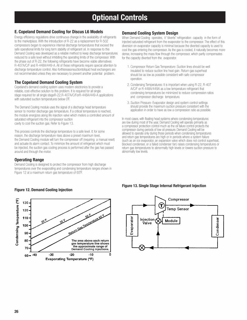
E. Copeland Demand Cooling for Discus L6 ModelsEnergy efficiency regulations drive continuous change in the availability of refrigerants to the marketplace. With the introduction of R-22 as a replacement for R-502 compressors began to experience internal discharge temperatures that exceed the safe operational limits for long term stability of refrigerant oil. In response to this Demand Cooling was developed as a reliable method to keep discharge temperatures reduced to a safe level without inhibiting the operating limits of the compressor. With the phase out of R-22, the following refrigerants have become viable alternatives: R-407A/C/F and R-448A/449-A. All of these refrigerants require special attention to discharge temperature control. Also forthisreasonsuctiontoliquid heat exchangers are not recommended unless they are necessary to prevent another potential problem.
The Copeland Demand Cooling SystemCopeland's demand cooling system uses modern electronics to provide a reliable, cost-effective solution to this problem. It is required for all single stage required for all single stageR-22,R-407A/C/ForR-448A/449-A applications with saturated suction temperatures below 0˚F.
The Demand Cooling module uses the signal of a discharge head temperature sensor to monitor discharge gas temperature. If a critical temperature is reached, the module energizes along life injection valve which meters a controlled amount of saturated refrigerant into the compressor suctioncavity to cool the suction gas. Refer to Figure 13.
This process controls the discharge temperature to a safe level. If, for some reason, the discharge temperature rises above a preset maximum level, the Demand Cooling module will turn the compressor off (requiring a manual reset) and actuate its alarm contact. To minimize the amount of refrigerant which must be injected, the suction gas cooling process is performed after the gas has passed around and through the motor.
Operating RangeDemand Cooling is designed to protect the compressor from high discharge temperatures over the evaporating and condensing temperature ranges shown in Figure 12 at a maximum return gas temperature of 65˚F.
Figure 12. Demand Cooling Injection
Demand Cooling System DesignWhen Demand Cooling operates, it “diverts” refrigeration capacity in the form of injected saturated refrigerant from the evaporator to the compressor. The effect of this diversion on evaporator capacity is minimal because the diverted capacity is used to cool the gas entering the compressor. As the gas is cooled, it naturally becomes more dense, increasing the mass flow through the compressor, which partly compensates for the capacity diverted from the evaporator. 1. Compressor Return Gas Temperature: Suction lines should be well insulated to reduce suction line heat gain. Return gas superheat should be as low as possible consistent with safe compressor operation.
2. Condensing Temperatures: It is important when using R-22, R-407 A/C/F or R-448A/449A as a low temperature refrigerant that condensing temperatures be minimized to reduce compression ratios and compressor discharge temperature.
3. Suction Pressure: Evaporator design and system control settings should provide the maximum suction pressure consistent with the application in order to have as low a compression ratio as possible. In most cases, with floating head systems where condensing temperatures are low during most of the year, Demand Cooling will operate primarily as a compressor protection control much as the oil failure control protects the compressor during periods of low oil pressure. Demand Cooling will be allowed to operate only during those periods when condensing temperatures and return gas temperatures are high or in periods where a system failure (such as an ice evaporator, an expansion valve which does not control superheat, blocked condenser, or a failed condenser fan) raises condensing temperatures or return gas temperatures to abnormally high levels or lowers suction pressure to abnormally low levels.
Figure 13. Single Stage Internal Refrigerant Injection

27
Field Wiring
WARNING: All wiring must be done in accordance with applicable codes and local ordinances.
The field wiring should enter the areas as provided on the unit. The wiring diagram for each unit is located on the inside of the electrical panel door. All field wiring should be done in a professional manner and in accordance with all governing codes. Before operating unit, double check all wiring connections, including the factory terminals. Factory connections can vibrate loose during shipment.
1. The serial data tag on the unit is marked with the electrical characteristic for wiring the unit
2. Consult the wiring diagram in the unit cooler and in the condensing unit for proper connections
3. Wire type should be of copper conductor only and of the proper size to handle the connected load
4. The unit must be grounded
Wiring Installation
General Installation• Refer to wiring schematic shipped on units for unit wiring.• The hot gas controller is shipped with preset control settings that are typical for
the application. Changes should be made according to directions outlined under Program Settings.
• The condensing unit electrical panel contains the electronic control board. The control board has a terminal block that is labeled to match the low voltage wiring connections going to the evaporator(s). The temperature and pressure sensors located on the condensing unit are pre-connected to the control board at the factory.
Wiring InstallationWiring between the condensing unit and the unit cooler(s) will be as follows (see wiring diagrams):
High voltage – A separate power supply from the condensing unit may be utilized for the evaporator. All appropriate local codes regarding disconnects and fusing must be followed. See the unit cooler spec. plate for ampacity.
Low voltage – 24 VAC control circuit. Each evaporator connects to the condensing unit with the following connections: defrost termination temperature (2 conductors), liquid line solenoid (2 conductors), evaporator fan contactor control (2 conductors). In addition, some evaporators will require 2 conductors for the pan heater contactor control. Eight-conductor, 18 gauge thermostat wiring is recommended. The thermostat contact connection can be run within this bundle of wires also if there are extra wires available. All 24 volt wiring must be run separate from the line voltage wiring.
Low voltage wiring must be 18 gauge minimum. For low voltage wiring, maximum distance is 500 feet from condensing unit to evaporators.
Alarm circuit – The onboard alarm is a dry set of contacts (Com, NO, NC) which activates to indicate an alarm. The type and wiring for the alarm is customer specified. Note that the alarm circuit does not distinguish or indicate what has caused the alarm. The maximum contact rating is 120V, 0.5A.
Mohave Hot Gas System Controller Battery Back-Up - The control board has a CR2032 (3V) back-up battery with an expected life of 10 years. In the event of battery failure; the system will lose time during power outages but will otherwise operate normally.
Mohave Modbus RS-485The "A" and "B" terminal signals should be connected to the PC host, and the "COM" terminal should be connected to the PC's digital ground.
If the green LED (BUS indicator) is 'ON' when "A" and "B" are connected to the PC, then these terminals should be swapped so the green LED is 'OFF'.
The green LED should flash when the PC host sends a mod-bus message, andthe yellow LED (XMIT indicator) should flash when the Mohave board responds to a query.
Communication Settings:-Baud Rate: 9600-Parity: Even-Data Bits: 8-Stop Bits: 1

28
Wiring Diagram
(24V)
(Standard Independent Evaporator Power Supply)
CONTROL BOARD
(Field supplied, not used when auxiliary temperature sensor is field installed and activated to control room temperature)

29
(24V)
Wiring Diagram
(Standard Independent Evaporator Power Supply)
CONTROL BOARD
(Field supplied, not used when auxiliary temperature sensor is field installed and activated to control room temperature)

30
T3T1 T2
MTR
** USE COPPER CONDUCTORS ONLY**
PART NO. 29781301 REV D
Mfg. NOTES: 1. WIRE NUMBERS MATCH WIRE MARKER NUMBERS ON HARNESS ASSEMBLIES.
Heatcraft Refrigeration Products LLC
3B 5 6 7XN3A4
MTR
MTR
JXN34
H1 H2 H3 F1 F2 F3
* ROOM THERMOSTAT ( FIELD SUPPLIED )
24 VAC18 GA. MIN.
EVAP DEFROST SUCTIONTEMPSENSOR
LIQUID LINESOLENOID
208-230V / 3 / 60 HZ -OR-575V / 3 / 60HZFOR SINGLE PHASESEE NOTE # 2
DRAINPAN HEATERS
EVAPORATORFAN MOTORS
7
FANCONTACTOR
HEATERCONTACTOR
8
1 2 3
2. FOR 208-230/1/60 HZ WIRE TO T1 & T2
CONDENSING UNIT
MTR
MTR
MTR
F1 F2
SINGLE PHASEDETAIL
EVAP FAN C
EVAPDEFR. HTR.
LIQ. LINESOL.
T-STAT C
EVAPDEFR.TEMP
4 5 69 10
RED
BLACK
BLUE
YELLOW
FIELD WIRING
30 A
MODELS 1860& 2120 ONLY
EVAPORATOR ELECTRICAL END
EVAPORATOR HEADER END
* NOTE: NOT USED WHEN AUX TEMPERATURE SENSOR IS FIELD-INSTALLED AND ACTIVATED TO CONTROL ROOM TEMPERATURE
Typical Evaporator Wiring (Electric Drain Pan Heater)(Standard Independent Evaporator Power Supply)
Wiring Diagram

31
T3T1 T2
EVAPORATOR ELECTRICAL END
MTR
** USE COPPER CONDUCTORS ONLY**
PART NO. 29781201 REV B
2. FOR 208-230/1/60 OR 460/1/60 WIRE TO T1 & T2
EVAPORATOR HEADER END
Heatcraft, Inc.
3B 5 6 7XN3A4
MTR
MTR
JXN34
H1 H2 H3 F1 F2 F3
CONDENSING UNIT
ROOM THERMOSTAT *( FIELD SUPPLIED )
24 VAC18 GA. MIN.
EVAP DEFROST SUCTIONTEMPSENSOR
LIQUID LINESOLENOID
208-230V / 3 / 60 HZ460V / 3 / 60HZ575V / 3 / 60HZ FOR SINGLE PHASESEE NOTE #2
EVAPORATORFAN MOTORS3 PHASE
FANCONTACTOR
18-2SOLENOIDHARNESS
Mfg. NOTES: 1. WIRE NUMBERS MATCH WIRE MARKER NUMBERS ON HARNESS ASSEMBLIES.
MTR
MTR
MTR
F1 F2
SINGLE PHASEDETAIL
4 5 6
1 2 3
EVAP FAN C
EVAPDEFR.TEMP
LIQ. LINESOL.
T-STAT C
RED
BLACK
FIELD WIRING
* NOTE: NOT USED WHEN AUX TEMPERATURE SENSOR IS FIELD-INSTALLED AND ACTIVATED TO CONTROL ROOM TEMPERATURE
Typical Evaporator Wiring (Hot Gas Drain Pan)
Wiring Diagram
(Standard Independent Evaporator Power Supply)

32
Typical Evaporator Wiring (Electric Drain Pan Heater)
Wiring Diagram
(Optional Evaporator Powered Off Condensing Unit)
(Field supplied, not used when auxiliary temperature sensor is field installed and activated to control room temperature)
MTR
** USE COPPER CONDUCTORS ONLY**
PART NO. 29781801 REV D
1.FOR 208-230/1/60 WIRE TO T1 & T2 AND F1 & F2
Heatcraft Refrigeration Products LLC
3B 5 6 7XN3A4
MTR
MTR
JXN34
H1 H2 H3 F1 F2 F3
CONDENSING UNIT
24 VAC18 GA. MIN.
EVAP DEFROST SUCTIONTEMPSENSOR LIQUID LINE
SOLENOID
208-230V / 3 / 60 HZ -OR-575V / 3 / 60 HZFOR SINGLE PHASESEE NOTE #1
EVAPORATORFAN MOTORS3 PHASE
FANCONTACTOR
18-2SOLENOIDHARNESS
Mfg. NOTES:
MTR
MTR
MTR
F1 F2
SINGLE PHASEDETAIL
EVAP FAN C
EVAPDEFR.TEMP
LIQ. LINESOL.
T-STAT C
FIELD WIRING
HEATERCONTACTOR
EVAPDEFR. HTR
DRAINPAN HEATERS
CONDENSING UNIT ELECTRIC BOXEVAPORATOR ELECTRIC BOX
MODELS 1860& 2120 ONLY
* ROOM THERMOSTAT ( FIELD SUPPLIED )
EVAPORATOR ELECTRICAL END
EVAPORATOR HEADER END
* NOTE: NOT USED WHEN AUX TEMPERATURE SENSOR IS FIELD-INSTALLED AND ACTIVATED TO CONTROL ROOM TEMPERATURE

33
Typical Evaporator Wiring (Hot Gas Drain Pan)
Wiring Diagram
(Optional Evaporator Powered Off Condensing Unit)
(Field supplied, not used when auxiliary temperature sensor is field installed and activated to control room temperature)
MTR
** USE COPPER CONDUCTORS ONLY**
PART NO. 29781701 REV B
1.FOR 208-230/1/60 OR 460/1/60 WIRE TO T1 & T2 AND F1 & F2
Heatcraft, Inc.
3B 5 6 7XN3A4
MTR
MTR
JXN34
H1 H2 H3 F1 F2 F3
CONDENSING UNIT
24 VAC18 GA. MIN.
EVAP DEFROST SUCTIONTEMPSENSOR LIQUID LINE
SOLENOID
208-230V / 3 / 60 HZ460V / 3 / 60HZ575V / 3 / 60HZ FOR SINGLE PHASESEE NOTE #1
EVAPORATORFAN MOTORS3 PHASE
FANCONTACTOR
18-2SOLENOIDHARNESS
Mfg. NOTES:
MTR
MTR
MTR
F1 F2
SINGLE PHASEDETAIL
EVAP FAN C
EVAPDEFR.TEMP
LIQ. LINESOL.
T-STAT C
FIELD WIRING
CONDENSING UNIT ELECTRIC BOXEVAPORATOR ELECTRIC BOX
* ROOM THERMOSTAT ( FIELD SUPPLIED )
EVAPORATOR ELECTRICAL END
EVAPORATOR HEADER END
* NOTE: NOT USED WHEN AUX TEMPERATURE SENSOR IS FIELD-INSTALLED AND ACTIVATED TO CONTROL ROOM TEMPERATURE

34
Wiring Diagram(Standard Independent Evaporator Power Supply)
CONTACTS (Compressor proof )Comp Aux -- COMPRESSOR AUXILLARY
HPS ------- HIGH PRESSURE SWITCHFCS ------- FAN CYCLING SWITCH
DCM ------- DEMAND COOLING MODULE
CB ------- CIRCUIT BREAKERC ------- CONTACTOR
LEGEND
CM ------- COMPRESSOR MODULE
TDR ------- TIME DELAY RELAY
PLM ------- PHASE LOSS MONITOROPS ------- OIL PRESSURE SWITCH LSV ------- LIQUID SOLENOID VALVELPS ------- LOW PRESSURE SWITCH
F ------- FUSE
R ------- RELAY
SHEET 2 OF 2
USE COPPER CONDUCTORS ONLY
FACTORY WIRING
FIELD WIRINGCustomer:
Model #:
Unit Serial #:
WWS ------- WIRE WHEN SUPPLIED
COMP
C
CU Suct Press
0-300 PSIA
CU Liquid Press
0-500 PSIARED
BLUE
Evap
#1
Def
Tem
p
Beac
on C
omp
ress
or
Evap
#2
Def
Tem
p
CONNECTIONSFIELD WIRING
Rem
ote
Def
r
T-ST
AT
Evap
Fan
C
SUCTION PRESSURE
LIQUID PRESSURE
Cond Fan #4
LIQ
LIN
E SO
L2
LIQ
LIN
E SO
L1
C EVA
P PA
N H
TR
C
Cond Fan #3
Cond Fan #2
Cond Fan #1
REGULATOR
Ambient Temp
CU Suct Temp
WHITE
BLUE
n/ocC1
AMBIENT TEMP
AUX TEMP
SUCTION TEMP
Alarm
SAFETY CKT.
SERVICE SW.
PRESSURE
SHEET 1TO
Redundant LPS
Defrost Sol
Bypass Valve
Suction Sol
3-Way Sol.
0
Redundant LPS
Bypass Valve
Suction Sol
37
36
35
34
Defrost Sol
3-Way Sol.
24V
24VC
33
32
31
30
R11
240
230V
C C240
208-230V/60HZ/3Ø - CONDENSING UNIT - CONTROL BOARD WIRING
C4
C3
n/ocC2
BDV2702L6C
test
Rev 3.24
T1
7
L1
CT ------- CURRENT TRANSDUCER (IN CMPR EBOX)
Unit Serial #:
Customer:
Model #:DHC ------- DEFROST HEATER CONTACTOREFC ------- EVAPORATOR FAN CONTACTORF ------- FUSE
C ------- CONTACTORCB ------- CIRCUIT BREAKER
FC ------- FAN CAPACITORFM ------- FAN MOTOR
LEGEND
FACTORY WIRING
FIELD WIRING
USE COPPER CONDUCTORS ONLY
SHEET 1 OF 2
BLUEYELLOW
8
COMP
BLU
E
2
TDR
L1
HPS
4R1
12 13
L2
HPSLPS DT
YEL
LOW 11
CRANKCASEHEATER R17
10
C1
AUX2
SERVICE MATE
OPS AUX1
LLS
CMOD
3
CONTACTOR C1
L2
L3
L1T1
T2
T32
1
COMPRESSOR
BLOCKPOWER
F2F1
SHEET 2TO
208-230V/60Hz/3Ø - CONDENSING UNIT - UNIT WIRING
F3
9
FM1
T2
8
L2
FM2
C3 C4
L2
T2T1T3
10 11
L1L3
12
T3
L3
C2
L1
L2
L3
CONTACTOR C2
T2
T36
5
T14
142
OPS
240 M L
15 16
17
CT
FM
BDV2702L6C
test
Rev 3.24
HEADER/COMPRESSOR END
M1
M2
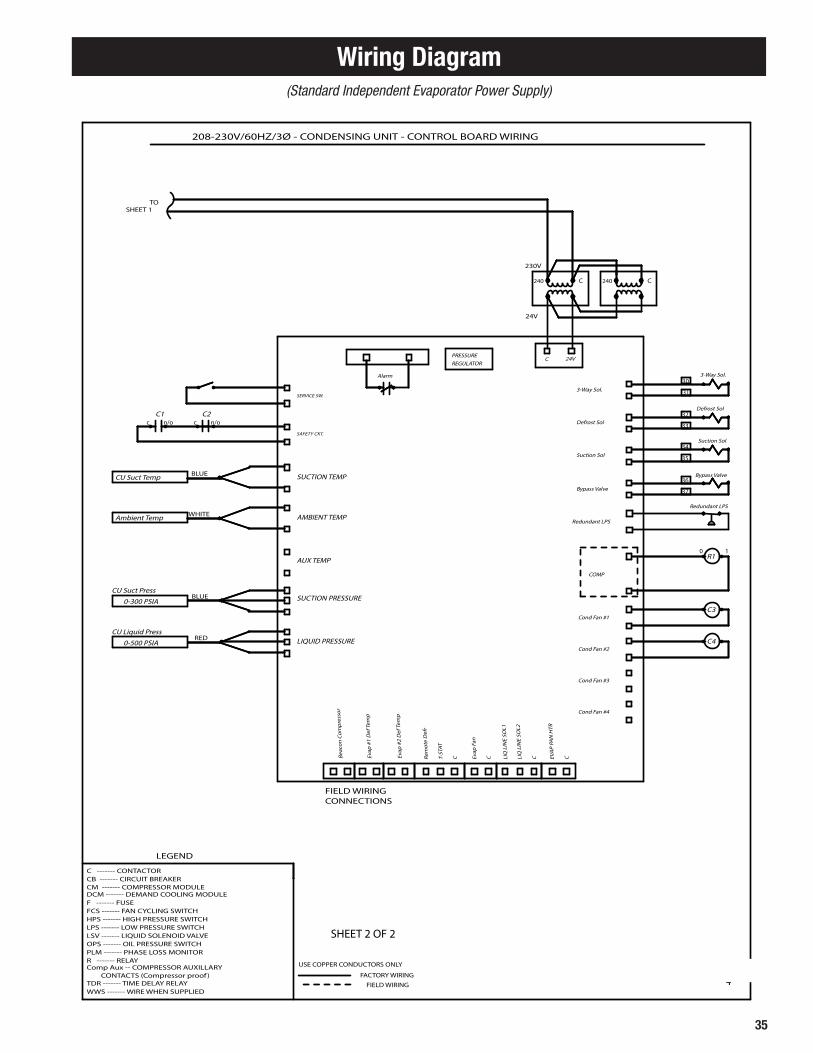
35
CONTACTS (Compressor proof )Comp Aux -- COMPRESSOR AUXILLARY
HPS ------- HIGH PRESSURE SWITCHFCS ------- FAN CYCLING SWITCH
DCM ------- DEMAND COOLING MODULE
CB ------- CIRCUIT BREAKERC ------- CONTACTOR
LEGEND
CM ------- COMPRESSOR MODULE
TDR ------- TIME DELAY RELAY
PLM ------- PHASE LOSS MONITOROPS ------- OIL PRESSURE SWITCH LSV ------- LIQUID SOLENOID VALVELPS ------- LOW PRESSURE SWITCH
F ------- FUSE
R ------- RELAY
SHEET 2 OF 2
USE COPPER CONDUCTORS ONLY
FACTORY WIRING
FIELD WIRINGCustomer:
Model #:
Unit Serial #:
WWS ------- WIRE WHEN SUPPLIED
COMP
C
CU Suct Press
0-300 PSIA
CU Liquid Press
0-500 PSIARED
BLUE
Evap
#1
Def
Tem
p
Beac
on C
omp
ress
or
Evap
#2
Def
Tem
p
CONNECTIONSFIELD WIRING
Rem
ote
Def
r
T-ST
AT
Evap
Fan
C
SUCTION PRESSURE
LIQUID PRESSURE
Cond Fan #4
LIQ
LIN
E SO
L2
LIQ
LIN
E SO
L1
C EVA
P PA
N H
TR
C
Cond Fan #3
Cond Fan #2
Cond Fan #1
REGULATOR
Ambient Temp
CU Suct Temp
WHITE
BLUE
n/ocC1
AMBIENT TEMP
AUX TEMP
SUCTION TEMP
Alarm
SAFETY CKT.
SERVICE SW.
PRESSURE
SHEET 1TO
Redundant LPS
Defrost Sol
Bypass Valve
Suction Sol
3-Way Sol.
0
Redundant LPS
Bypass Valve
Suction Sol
37
36
35
34
Defrost Sol
3-Way Sol.
24V
24VC
33
32
31
30
R11
240
230V
C C240
208-230V/60HZ/3Ø - CONDENSING UNIT - CONTROL BOARD WIRING
C4
C3
n/ocC2
BDV2702L6C
test
Rev 3.24
T1
7
L1
CT ------- CURRENT TRANSDUCER (IN CMPR EBOX)
Unit Serial #:
Customer:
Model #:DHC ------- DEFROST HEATER CONTACTOREFC ------- EVAPORATOR FAN CONTACTORF ------- FUSE
C ------- CONTACTORCB ------- CIRCUIT BREAKER
FC ------- FAN CAPACITORFM ------- FAN MOTOR
LEGEND
FACTORY WIRING
FIELD WIRING
USE COPPER CONDUCTORS ONLY
SHEET 1 OF 2
BLUEYELLOW
8
COMP
BLU
E
2
TDR
L1
HPS
4R1
12 13
L2
HPSLPS DT
YEL
LOW 11
CRANKCASEHEATER R17
10
C1
AUX2
SERVICE MATE
OPS AUX1
LLS
CMOD
3
CONTACTOR C1
L2
L3
L1T1
T2
T32
1
COMPRESSOR
BLOCKPOWER
F2F1
SHEET 2TO
208-230V/60Hz/3Ø - CONDENSING UNIT - UNIT WIRING
F3
9
FM1
T2
8
L2
FM2
C3 C4
L2
T2T1T3
10 11
L1L3
12
T3
L3
C2
L1
L2
L3
CONTACTOR C2
T2
T36
5
T14
142
OPS
240 M L
15 16
17
CT
FM
BDV2702L6C
test
Rev 3.24
HEADER/COMPRESSOR END
M1
M2
Wiring Diagram(Standard Independent Evaporator Power Supply)
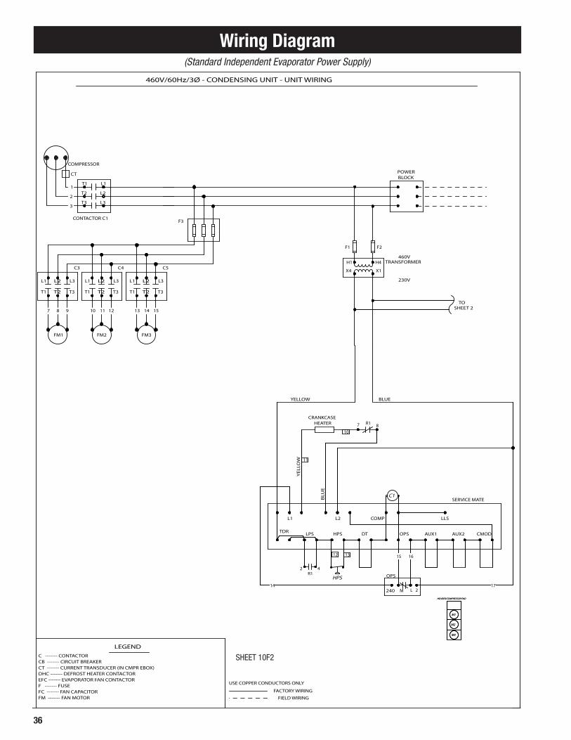
36
Wiring Diagram
CT ------- CURRENT TRANSDUCER (IN CMPR EBOX)
Unit Serial #:
Customer:
Model #:DHC ------- DEFROST HEATER CONTACTOREFC ------- EVAPORATOR FAN CONTACTORF ------- FUSE
C ------- CONTACTORCB ------- CIRCUIT BREAKER
FC ------- FAN CAPACITORFM ------- FAN MOTOR
LEGEND
FACTORY WIRING
FIELD WIRING
USE COPPER CONDUCTORS ONLY
SHEET 1 OF 2
CONTACTS (Compressor proof )Comp Aux -- COMPRESSOR AUXILLARY
HPS ------- HIGH PRESSURE SWITCHFCS ------- FAN CYCLING SWITCH
DCM ------- DEMAND COOLING MODULE
CB ------- CIRCUIT BREAKERC ------- CONTACTOR
LEGEND
CM ------- COMPRESSOR MODULE
TDR ------- TIME DELAY RELAY
PLM ------- PHASE LOSS MONITOROPS ------- OIL PRESSURE SWITCH LSV ------- LIQUID SOLENOID VALVELPS ------- LOW PRESSURE SWITCH
F ------- FUSE
R ------- RELAY
SHEET 2 OF 2
USE COPPER CONDUCTORS ONLY
FACTORY WIRING
FIELD WIRINGCustomer:
Model #:
Unit Serial #:
WWS ------- WIRE WHEN SUPPLIED
BLUEYELLOW
8
COMP
BLU
E
2
TDR
L1
HPS
4R1
12 13
L2
HPSLPS DT
YEL
LOW 11
CRANKCASEHEATER R17
10
C1
AUX2
SERVICE MATE
OPS AUX1
LLS
CMOD
3
CONTACTOR C1
L2
L3
L1T1
T2
T32
1
COMPRESSOR
BLOCKPOWER
COMP
C
CU Suct Press
0-300 PSIA
CU Liquid Press
0-500 PSIARED
BLUE
Evap
#1
Def
Tem
p
Beac
on C
omp
ress
or
Evap
#2
Def
Tem
p
CONNECTIONSFIELD WIRING
Rem
ote
Def
r
T-ST
AT
Evap
Fan
C
SUCTION PRESSURE
LIQUID PRESSURE
Cond Fan #4
LIQ
LIN
E SO
L2
LIQ
LIN
E SO
L1
C EVA
P PA
N H
TR
C
Cond Fan #3
Cond Fan #2
Cond Fan #1
REGULATOR
Ambient Temp
CU Suct Temp
WHITE
BLUE
n/ocC1
AMBIENT TEMP
AUX TEMP
SUCTION TEMP
Alarm
SAFETY CKT.
SERVICE SW.
PRESSURE
SHEET 1TO
Redundant LPS
Defrost Sol
Bypass Valve
Suction Sol
3-Way Sol.
0
Redundant LPS
Bypass Valve
Suction Sol
37
36
35
34
Defrost Sol
3-Way Sol.
24V
24VC
33
32
31
30
R11
240
230V
C C240
230V
460V
SHEET 2TO
F1 F2
X4
H1
X1
H4 TRANSFORMER
460V/60Hz/3Ø - CONDENSING UNIT - UNIT WIRING 460V/60HZ/3Ø - CONDENSING UNIT - CONTROL BOARD WIRING
FM3
1513 14
T1
L1
T2
L2
T3
L3
C5
C5
C4
C3
F3
C4
L3L2
C3
L3 L1
121110
FM2
T1T3 T3T2
L2L1
87
FM1
T2T1
9
142
OPS
240 M L
15 16
17
CT
BDV3502M6D BDV3502M6D
Test Test
Rev 3.24Rev 3.24
HEADER/COMPRESSOR END
M1
M2M2
M1
HEADER/COMPRESSOR END
M3M3
(Standard Independent Evaporator Power Supply)
SHEET 10F2

37
Wiring Diagram
CT ------- CURRENT TRANSDUCER (IN CMPR EBOX)
Unit Serial #:
Customer:
Model #:DHC ------- DEFROST HEATER CONTACTOREFC ------- EVAPORATOR FAN CONTACTORF ------- FUSE
C ------- CONTACTORCB ------- CIRCUIT BREAKER
FC ------- FAN CAPACITORFM ------- FAN MOTOR
LEGEND
FACTORY WIRING
FIELD WIRING
USE COPPER CONDUCTORS ONLY
SHEET 1 OF 2
CONTACTS (Compressor proof )Comp Aux -- COMPRESSOR AUXILLARY
HPS ------- HIGH PRESSURE SWITCHFCS ------- FAN CYCLING SWITCH
DCM ------- DEMAND COOLING MODULE
CB ------- CIRCUIT BREAKERC ------- CONTACTOR
LEGEND
CM ------- COMPRESSOR MODULE
TDR ------- TIME DELAY RELAY
PLM ------- PHASE LOSS MONITOROPS ------- OIL PRESSURE SWITCH LSV ------- LIQUID SOLENOID VALVELPS ------- LOW PRESSURE SWITCH
F ------- FUSE
R ------- RELAY
SHEET 2 OF 2
USE COPPER CONDUCTORS ONLY
FACTORY WIRING
FIELD WIRINGCustomer:
Model #:
Unit Serial #:
WWS ------- WIRE WHEN SUPPLIED
BLUEYELLOW
8
COMP
BLU
E
2
TDR
L1
HPS
4R1
12 13
L2
HPSLPS DT
YEL
LOW 11
CRANKCASEHEATER R17
10
C1
AUX2
SERVICE MATE
OPS AUX1
LLS
CMOD
3
CONTACTOR C1
L2
L3
L1T1
T2
T32
1
COMPRESSOR
BLOCKPOWER
COMP
C
CU Suct Press
0-300 PSIA
CU Liquid Press
0-500 PSIARED
BLUE
Evap
#1
Def
Tem
p
Beac
on C
omp
ress
or
Evap
#2
Def
Tem
p
CONNECTIONSFIELD WIRING
Rem
ote
Def
r
T-ST
AT
Evap
Fan
C
SUCTION PRESSURE
LIQUID PRESSURE
Cond Fan #4
LIQ
LIN
E SO
L2
LIQ
LIN
E SO
L1
C EVA
P PA
N H
TR
C
Cond Fan #3
Cond Fan #2
Cond Fan #1
REGULATOR
Ambient Temp
CU Suct Temp
WHITE
BLUE
n/ocC1
AMBIENT TEMP
AUX TEMP
SUCTION TEMP
Alarm
SAFETY CKT.
SERVICE SW.
PRESSURE
SHEET 1TO
Redundant LPS
Defrost Sol
Bypass Valve
Suction Sol
3-Way Sol.
0
Redundant LPS
Bypass Valve
Suction Sol
37
36
35
34
Defrost Sol
3-Way Sol.
24V
24VC
33
32
31
30
R11
240
230V
C C240
230V
460V
SHEET 2TO
F1 F2
X4
H1
X1
H4 TRANSFORMER
460V/60Hz/3Ø - CONDENSING UNIT - UNIT WIRING 460V/60HZ/3Ø - CONDENSING UNIT - CONTROL BOARD WIRING
FM3
1513 14
T1
L1
T2
L2
T3
L3
C5
C5
C4
C3
F3
C4
L3L2
C3
L3 L1
121110
FM2
T1T3 T3T2
L2L1
87
FM1
T2T1
9
142
OPS
240 M L
15 16
17
CT
BDV3502M6D BDV3502M6D
Test Test
Rev 3.24Rev 3.24
HEADER/COMPRESSOR END
M1
M2M2
M1
HEADER/COMPRESSOR END
M3M3
(Standard Independent Evaporator Power Supply)

38
(Standard Independent Evaporator Power Supply with VFD Condenser Fans)
Wiring Diagram

39
(Standard Independent Evaporator Power Supply with VFD Condenser Fans)
Wiring Diagram

40
Hot Gas Unit Cooler Typical Factory Piping
ElectricalConnections(this side)
Note: Control contactorsmount under a coveron front of unit (not shown)
SuctionConnection
LiquidConnection
LiquidSolenoidValve
ThermostaticExpansionValve
CheckValves
CheckValve
SuctionP-Trap
Hot GasDShown
rain Pan
AirFlow

41
Hot Gas Condensing Unit Typical Factory Piping
3-WAY VALVE(NO BLEED
PORT)
SUCTIONACCUMULATOR
LIQUIDRECEIVER
SUCTIONSOLENOID(NC)
SUCTIONFILTERLIQUID
SIGHTGLASS
LIQUIDFILTERDRIER
BASEVALVE
BASEVALVE
BY-PASSSOLENOID
DEFROSTSOLENOID(NC)
CHECKVALVE
LIQUIDFILTERDRIER
CHECKVALVE
ELECTRONICPRESSURE
REGULATOR
COMPRESSOR
CHECKVALVE
PIPINGb.dftrev.B
REDUNDANTLOW PRESSURESWITCH LOCATION
LIQUID PRESSURESENSOR LOCATION
SUCTION PRESSURESENSOR LOCATION
BY-PASSSOLENOID
VALVE
SUCTION STOPSOLENOID VALVE(NC)
DEFROSTSOLENOID VALVE(NC)

42
Refrigeration Operation
Refrigeration OperationThe refrigeration operation of the Mohave Hot Gas System is very similar to a standard refrigeration system. An external thermostat is connected to the hot gas control board at the terminal block connections labeled T-Stat and C (for common). When the normally open contact inside the thermostat closes (a call for cooling), the hot gas control board responds by activating a series of solenoids and contactors (described below) in order to initiate and maintain a refrigeration cycle. Later, when the thermostat contact opens, the hot gas control board deactivates the solenoids in a preset manner in order to safely turn off the refrigeration process and maintain an Off condition.
At initial power up, the system defaults to the OFFmode for a minimum of two minutes. Following the two-minute hold off period, the control circuit examines the state of the thermostat input. If the thermostat input signal is activated (closed between T-Stat and C), the system begins the refrigeration startup process. Full refrigeration mode (or COOLmode) is achieved when the control board has activated the solenoids necessary to provide refrigerant flow between the evaporator(s) and the condensing unit (Suction Solenoid and Liquid Line Solenoid), activated the compressor contactor, deployed the appropriate control over the condenser fans, and turned onthe evaporator fans.
Refrigerant Solenoid and Compressor Contactor Control: The Suction Solenoid is initially activated following the power-up two-minute hold off time. It is maintained in the ON state until a defrost cycle is initiated. The timing of the liquid line solenoid (LLS) activation is based upon the saturated suction temperature (SST) which is calculated from the suction pressure value. If the SST is greater than 15ºF, the compressor contactor is activated before the LLS is activated in order to decrease the suction pressure prior to startup. When the SST drops to -5ºF, the LLS is activated. If the SST does not fallto -5ºF within 2 minutes, Er12 is activated and the system goes to OFF mode.
If the SST is 15ºF or less, the LLS is activated immediately. When the SST rises to -10ºF for medium temperature applications or -20ºF for low temperature applications, the compressor contactor is activated. If the SST fails to rise in 2 minutes, Er11 is activated and the system goes toOFF mode.
When the thermostat signal is deactivated, the liquid line solenoid is turned off immediately. The compressor contactor will stay activated until the suction pressure falls below the pre-programmed cut out pressure. The compressor contactor and all condenser fan contactors will be deactivated simultaneously. The evaporator fans will continue running.
Condenser Fan Control: When the Condensing Unit Model is selected in the Program Review Menu; the program automatically activates the default Head Pressure Control Scheme.
Method: Pressure Fan Cycling (PRES) All fans Minimum condensing temperature: 65ºF. The default ON and OFF settings are optimized to maximize energy efficiency while still providing adequate pressure for the thermostatic expansion valve(s) to work properly. The parameters are refrigerant specific. Fans are staged to minimize fluctuations in head pressure during operation.
During refrigeration operation, the hot gas controller monitors liquid pressure to determine if each fan should be ON or OFF.
These settings and other fan control options may be modified by turning on the Expert Mode (XPRT) in the Program Menu. See Program Review and Optional Controls for more information.
Evaporator Fan Control: After initial power-up, the evaporator fans will be turned off. When the system initiates the first cooling cycle, the hot gas controller monitors the temperature value of the evaporator defrost termination sensor mounted on the evaporator suction headers. When the controller determines that the suction header has reached the refreeze setpoint, the evaporator fans will be activated. If there are two evaporators, the fans will be energized by the first sensor to achieve setpoint. Once activated, the evaporator fans will continue to run until either a defrost cycle is initiated, or if the system is placed in SERVICE mode.
Anti Short-Cycle Protection: During cooling mode, the control board is programmed to allow a minimum system ON time of 1 minute and a minimum OFF time of 2 minutes.
Pump DownAt the end of each cooling cycle, when the box temperature is met, the hot gas control system will pump down and turn off the compressor.
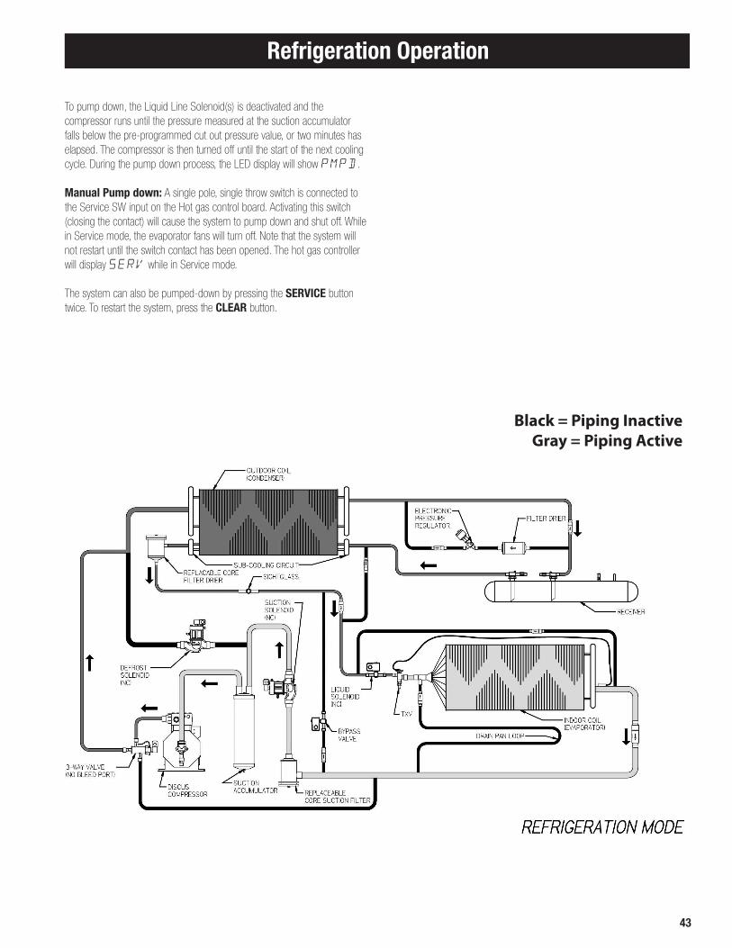
43
Refrigeration Operation
To pump down, the Liquid Line Solenoid(s) is deactivated and the compressor runs until the pressure measured at the suction accumulator falls below the pre-programmed cut out pressure value, or two minutes has elapsed. The compressor is then turned off until the start of the next cooling cycle. During the pump down process, the LED display will show PMPD.
Manual Pump down: A single pole, single throw switch is connected to the Service SW input on the Hot gas control board. Activating this switch (closing the contact) will cause the system to pump down and shut off. While in Service mode, the evaporator fans will turn off. Note that the system will not restart until the switch contact has been opened. The hot gas controller will display SERV while in Service mode.
The system can also be pumped-down by pressing the SERVICE button twice. To restart the system, press the CLEAR button.
Black = Piping InactiveGray = Piping Active

44
Defrost Operation
Defrost Operation
Defrost Timing/Schedule ProgrammingThe hot gas controller can be programmed with up to 12 defrost start times. The Program Review menu section describes the process to program or delete a valid start time. Note that clearing a start time by pressing CLEAR and the ENTER will disable all start times following the one being cleared. There must be 30 minutes of elapsed time following a start of defrost before another defrost can be scheduled. A defrost cycle can be initiated manually at any time.
Force Defrost ManuallyTo manually force the start of a defrost-cycle, press the FORCE DEFROST button. If the system is in COOLmode, the system will pump down and go to the off mode before the defrost process is started.
Defrost Process
The defrost process has four steps: Pre-defrost (DEF1) pressure equalization, Defrost operation (DEF2), Post-defrost (DEF3) pressure equalization and drain down, and Refreeze (FREZ).
DEF1:Pre-defrost, or defrost step 1, always follows activation of Off mode. If the system is in Cool mode when the defrost cycle is activated, the control will pump down and go to Off mode before activating pre-defrost.
The purpose of DEF1 is to equalize the refrigerant pressures between the condensing unit receiver and the evaporator(s). This is accomplished by first deactivating the evaporator fans, and the suction solenoid. Next the Bypass Solenoid and the evaporator Pan Heater contactor are activated.The time duration of the pressure equalization is programmed as EQUT in the PROGRAM REVIEW menu.
DEF2:After the equalization time has elapsed, the Bypass Solenoid is deactivated. The Defrost Solenoid is activated 1 second later, followed by the 3-Way valve solenoid 1 second after that. Next, the pressure regulator control algorithm is enabled. The initial position is full open, but it quickly makes adjustments in order to stabilize the pressures and temperatures seen at the inlet of the suction accumulator.
The compressor contactor turns on at the same time that the pressure regulator is activated. The ambient temperature is measured, and a determination is made of how many condenser fans should be operating. The correct number of condenser fans is activated at the same time as the compressor contactor.
During the DEF2 operation, the pressure regulator continues to maintain the appropriate volume of refrigerant flow through the system based upon the current ambient conditions, the refrigerant type, and the type of cooling application.
Termination of defrost is accomplished by either both evaporators reaching their target termination temps, or the liquid pressure measured between the receiver and the condenser coil reaching its target pressure, or the pre-programmed fail safe time.
When one of the termination factors is realized, the compressor, condenser fan(s), and the defrost solenoid are turned off. The 3-Way valve and the Pan heaters are left on. The pressure regulator is activated to 100% open, and DEF3 begins.
DEF3:Post-defrost has two purposes. The first is the transfer of high pressure refrigerant at the evaporator back to the condenser receiver by way of the pressure regulator. The pressure regulator is open 100% during this step. The second purpose is drain down time for the warm evaporators. This allows the water that was melted off of the coil to drain out of the evaporator drain pan. The time duration for this step is identical to the DEF1 equalization time.
After the completion of the delay time period, the 3-Way valve and the pan heater contactor are turned off. One second later the Suction Solenoid is turned on, and then one second after that the compressor turns on. The condenser fan control algorithm is also enabled. When the pressure measured at the suction sensor falls below -10°F SST, the liquid line solenoid is activated and the process step changes to Refreeze.
FREZ:The Refreeze step is identical to Cooling mode except that the evaporator fans are turned off. This is to allow the evaporator coils to freeze any remaining water that might be left over from the drain down step so that when the fans turn on, the water will not be sprayed into the refrigerated space. When the evaporator reaches the refreeze set-point, or the refreeze time limit elapses, the fans turn on and the system begins a cooling cycle. If the thermostat is satisfied, or deactivated, the system will run a cooling cycle for two minutes and then pump down and shut off.
After the compressor is energized, the suction stop valve may be pulsed to limit the suction pressure at the compressor.
Through the refreeze period and into cooling mode,the liquid solenoid may energize and de-energize to hold the evaporator below 10 °F SST and allow the expansion valve to better regulate as the system enters cooling mode.
Parameter LLSP controls the duration of this pulsing event.
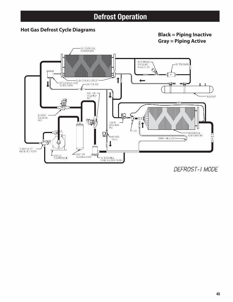
45
Defrost Operation
Black = Piping InactiveGray = Piping Active
Hot Gas Defrost Cycle Diagrams

46
Defrost Operation
Black = Piping InactiveGray = Piping Active
Hot Gas Defrost Cycle Diagrams

47
Defrost Operation
Defrost Termination ParametersThe hot gas controller uses a combination of temperature, pressure and time values to make the decision to end the defrost cycle. The Defrost Failsafe Time is used at all times to limit the length of defrost. At cool ambient temperatures, the controller checks both the temperature and pressure of the defrosting evaporator(s) before making a termination decision. In warm ambient temperatures, the Defrost Termination Pressure is used exclusively to insure that the evaporators remain in defrost for a sufficient length of time. When the controller is programmed, default temperature, pressure and time values are populated into settings. These default values were selected to fit the majority of applications. If necessary, these parameters may be accessed
and changed in Expert Mode.
Defrost Skip ParametersThe hot gas controller monitors refrigeration operation for several situations that would indicate that a defrost cycle is unnecessary. In these situations, the
controller will skip the next scheduled defrost.
Compressor run time is calculated since the last defrost cycle. If the run time is less that 30 minutes, the next defrost cycle is skipped.
When the measured saturated suction temperature is consistently above
32ºF, the defrost cycle is skipped.

48
Leak TestingAfter all lines are connected, the entire system must be leak tested. The complete system should be pressurized to not more than 150 psig with refrigerant and dry nitrogen (or dry CO
2). The use of an electronic type leak detector is highly
recommended because of its greater sensitivity to small leaks. As a further check it is recommended that this pressure be held for a minimum of 12 hours and then rechecked. For a satisfactory installation, the system must be leak tight.
Line InsulationAfter the final leak test, refrigerant lines exposed to high ambient conditions should be insulated to reduce heat pickup and prevent the formation of flash gas in the liquid lines. Suction lines must always be insulated with 3/4" wall Armstrong “Armaflex” or equal. When required, Liquid lines should be insulated with 1/2 inch wall insulation or better. The insulation located in outdoor environments should be protected from UV exposure to prevent deterioration of insulating value.
Evacuation
CAUTION: Do not use the refrigeration compressor to evacuate the system. Do not start the compressor while it is in a vacuum.
A good, deep vacuum pump should be connected to both the low and high side evacuation valves with copper tube or high vacuum hoses (1/4" ID minimum). If the compressor has service valves, they should remain closed. A deep vacuum gauge capable of registering pressure in microns should be attached to the system for pressure readings.
A shut off valve between the gauge connection and vacuum pump should be provided to allow the system pressure to be checked after evacuation. Do not turn off vacuum pump when connected to an evacuated system before closing shut off valve.
The vacuum pump should be operated until a pressure of 1,500 microns absolute pressure is reached — at which time the vacuum should be broken with the refrigerant to be used in the system through a drier until the system pressure rises above “0” psig.
NOTE: Refrigerant used during evacuation cannot be vented. Reclaim all used refrigerant. EPA regulations are constantly being updated to ensure your procedure follows correct regulations.
Repeat this operation a second time.
Open the compressor service valves and evacuate the entire system to 500 microns absolute pressure. Raise the pressure to 2 psig with the refrigerant and remove the vacuum pump.
Evacuation & Leak DetectionDue to the smaller molecule size of HFC’s, they will tend to leak more readily than CFC’s. Consequently, it is of the utmost importance that proper system evacuation and leak detection procedures be employed.
Copeland recommends a minimum evacuation to 500 microns. In addition, a vacuum decay test is strongly recommended to assure there is not a large pressure differential between the system and vacuum pump. Good evacuation processes include frequent vacuum pump oil changes and large diameter, short hose connections to both high and low sides of the system preferably using bronze braided hose.
Leak detection can be carried out in the conventional manner. If HCFC or CFC tracer gas is used, care must be taken to completely remove all traces of the gas prior to introducing HFC’s.
Electronic leak detectors are now available that will sense HFC’s. This is considered preferable since it removes the possibility of chlorine remaining in the system after leak testing with HCFC’s and/or CFC’s. There is a view that even small quantities of chlorine may act as a catalyst encouraging copper plating and/or corrosion and should therefore be avoided.
Within the last several years, manufacturers have developed fluorescent dye leak detection systems for use with refrigerants. These dyes mix with the lubricant and, when exposed to an ultraviolet light “fluoresce,” indicates the location of leaks. Copeland has tested and approved the Rigid “System Safe” dye and found it to be compatible with the compressor materials in systems.
Evacuation & Leak Detection
NOTE: The Hot Gas Control Board may be powered up and set on“EVAC” Mode during Evacuation. In this mode, all of the system valves are energized. See Page 47.

49
Start-Up Operation - Initial Power OnAt the initial application of power to the system, the compressor and the evaporator fans will be in a 2-minute hold-off cycle and will not start immediately. The 4-digit LED indicator located on the control board will display OFF. If the room thermostat setting is below the current room temperature, the contact inside the thermostat will be closed, and the associated T-Stat LED on the controller circuit board will be lit. Under these conditions, the system will begin a cooling cycle.
Operating Mode DisplayOFF Off ModeCOOL Cooling ModePMPD Pump DownSERV Service ModeDELY Delay ModeDEF1 Pre-Defrost, or Bypass ModeDEF2 Defrost ModeDEF3 Post-Defrost Equalization, or Drain ModeTEST Test Mode
Programming and Reviewing Settings and ChangesThe Program Review button is used to program, review and change all program settings for the system.
Press PROGRAM REVIEW button. The Setpoint item will appear on the LED. After a few seconds delay the Setpoint value will display. Each time the button is pressed a different item is displayed.
Next, use the SELECT knob to change value of Setpoint item.
Next, when the desired value is selected, press the ENTER button to place it in program memory. If the ENTER button is not pressed the value will not be stored in memory and thus will not be changed.
There are two levels of menu setting programs: Normal and Expert. The Expert settings are visible when the XPRT menu item is changed from Off to On.
Program Review (Items Available when in Normal Mode)
CLKH ....... Set the Time of Day clock hour valueCLKM ....... Set the Time of Day clock minute value°F°C ....... Set Fahrenheit/Celsius temperature units (°F/°C)1224 ....... Set Time display method (12HR / 24HR)ALRT ....... Set the Alarm Time (2 to 120 minutes)RDTf ....... Defrost schedule based upon compressor runtime (OFF or Defrost
based upon compressor runtime in 30 minute increments) Note that the time based menu choices below are diabled when RTDF is activated.
DF01 ....... Set Defrost #1 starting time (12:00 to 12:00 in 30 minute increments)DF02 ....... Set Defrost #2 starting timeDF03 ....... Set Defrost #3 starting timeDF04 ....... Set Defrost #4 starting timeDF12 ....... Set Defrost #12 starting timeAPPL ....... Set Application type (MED, LOW) REFR ....... Set Refrigerant type (R-22, R-404A, R-507, R-407A, R-407C, ...................... R-407F, R-448A and R-449A )MODL ....... Set Condensing Unit Model NumberXPRT ....... Activate expert menu items (Off, On)
Start-Up Operation and Program Review
Check Out and Start UpAfter the installation has been completed, the following points should be covered before the system is placed in operation: (a) Check all electrical and refrigerant connections. Be sure they are all tight. (b) Observe compressor oil level before start-up. The oil level should be
at or slightly above the 3/4 level of the sight glass. Refer to Table 7 on page 52 for proper compressor oil.
(c) Remove upper mounting nuts on the compressor feet. Remove the shipping spacers. Install the neoprene washers onto the compressor feet. Replace the upper mounting nuts and washers,allowing 1/16" space between the mounting nut and the neoprene spacer.
(d) Check high and low pressure controls, oil pressure safety controls, and all other safety controls, and adjust if necessary.
(e) Check the room thermostat for normal operation and adjust. (f) Wiring diagrams, instruction bulletins, etc. attached to the condensing
units should be read and filed for future reference. (g) All fan motors on air cooled condensers,evaporators, etc. should be
checked for proper rotation. Fan motor mounts should be carefully checked for tightness and proper alignment.
(h) Observe system pressures during charging and initial operation. Do not add oil while the system is short of refrigerant unless oil level is dangerously low.
(i) Continue charging until system has sufficient refrigerant for proper operation. Do not overcharge. Remember that bubbles in a sight glass may be caused by a restriction as well as a shortage of refrigerant.
(j) Do not leave unit unattended until the system has reached normal operating conditions and the oil charge has been properly adjusted to maintain the oil level between 1/2 and 1/4 of the sight glass.
(k) Make sure all Schrader valve caps are in place and tight
CAUTION: Extreme care must be taken in starting compressors for the first time after system charging. At this time, all of the oil and most of the refrigerant might be in the compressor creating a condition which could cause compressor damage due to slugging. Activating the crankcase heater for 24 hours prior to start-up is required. If no crankcase heater is present, then directing a 500 watt heat lamp or other safe heat source on the lower shell of the compressor for approximately thirty minutes will be beneficial in eliminating this condition which might never reoccur.
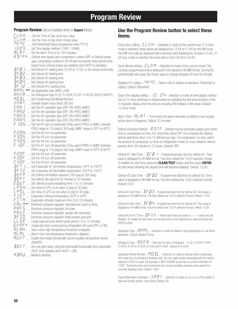
50
Program Review
Program Review (Items Available when in Expert Mode) CLKH ....... Set the Time of Day clock hour valueCLKM ...... Set the Time of Day clock minute value°F°C ...... Set Fahrenheit/Celsius temperature units (°F/°C)1224 ...... Set Time display method (12HR. / 24HR)ALRT ...... Set the Alarm Time (2 to 120 minutes)RDTF* . ...Defrost time based upon compressor runtime (OFF or Defrost based .................... upon compressor runtime in 30 minute increments) Note that the time .................... based menu choices below are disabled when RDTF is activated.DF01 ...... Set Defrost #1 starting time (12:00 to 12:00. in 30 minute increments)DF02 ...... Set Defrost #2 starting timeDF03 ...... Set Defrost #3 starting timeDF04 ...... Set Defrost #4 starting timeDF12 ...... Set Defrost #12 starting timeAPPL*** . Set Application type (MED, LOW) REFR ...... Set Refrigerant type R-22, R-404A, R-507, R-407A, R407C,R407F)MODL ...... Set Condensing Unit Model NumberXPRT ...... Activate expert menu items (Off, On)FAN1 ...... Set Fan #1 operation type (OFF, ON, PRES, AMBT)FAN2 ...... Set Fan #2 operation type (OFF, ON, PRES, AMBT)FAN3 ...... Set Fan #3 operation type (OFF, ON, PRES, AMBT)FAN4 ...... Set Fan #4 operation type (OFF, ON, PRES, AMBT)F1ON ...... Set Fan #1 turn-on parameter (Only used if PRES or AMBT selected.
PRES range is 110 psig to 300 psig, AMBT range is 30°F to 90°F).F2ON ...... Set Fan #2 turn-on parameterF3ON ...... Set Fan #3 turn-on parameterF4ON ...... Set Fan #4 turn-on parameterF1OF ...... Set Fan #1 turn-off parameter (Only used if PRES or AMBT selected.
PRES range is 110 psig to 300 psig, AMBT range is 30°F to 90°F).F2OF ...... Set Fan #2 turn-off parameterF3OF ...... Set Fan #3 turn-off parameterF4OF ...... Set Fan #4 turn-off parameterDFT1 ...... Set Evaporator #1 termination temperature ( 50°F to 100°F)DFT2 ...... Set Evaporator #2 termination temperature ( 50°F to 100°F)DEFP ...... Set Defrost termination pressure (160 psig to 300 psig)DEFT ...... Set Defrost fail-safe time (5 minutes to 30 minutes)EQUT ...... Set defrost process equalizing time (1 to 10 minutes)LPSH ...... Set value of LPS cut-in value (0 psig to 30 psig)LPSL ...... Set value of LPS cut-out value (0 psig to 30 psig)FZET ...... Evaporator refreeze temperature (20ºF to 40ºF)FZTM ...... Evaporator refreeze maximum time (0 to 10 minutes)VALM** .. Electronic pressure regulator manufacturer (Carel or Alco)PRFS ...... Electronic pressure regulator full scalePRUI ...... Electronic pressure regulator update rate (seconds)DFIO . .. .Electronic pressure regulator initial position (percent)LLSP . .. Liquid solenoid post defrost pulse period ( 0 to 15 minutes)EVPF* . .. Evaporator fans running during refrigeration off-cycle (OFF or ON)ALRH ...... Alarm room high temperature threshold in degreesALRL ...... Alarm room low temperature threshold in degreesAUXT ...... Enable thermostat functionality via the auxiliary temperature sensor
(ON/OFF)BOXT ...... Box set point when using the thermostat functionality from parameter
AUXT (only appears when AUXT = ON)MBAd ...... Modbus address
Use the Program Review button to select these items:
Clock Hour setting – CLKH – Selection is made of the current hour. If 12 hour mode is selected, these values are displayed as 12:XX to 11:XX for the AM hours. The PM hours will be displayed with a decimal point following the minutes (12:XX.). If 24 hour mode is selected, the hours will run from 00:XX to 23:XX.
Clock Minute setting – CLKM – Selection is made of the current minute. The currently programmed time is displayed in the standard HH:MM format. Turning the potentiometer will cause the minute value to change between 00 and 59 minutes.
Degrees F/C setting – °F°C– Select units to display temperature. Fahrenheit or Celsius. Default: Fahrenheit.
Clock Time display setting – 12 24– Selection is made of time display method. Use of 12-Hour technique is implemented by activating the last decimal place of the 4-character display when the time is indicating PM instead of AM values. Default: 12-Hour mode.
Alarm Time – ALRT – Time which the alarm elements conditions must exceed before alarm is triggered. Default: 20 minutes.
Defrost schedule method1 - RDTF - Defrost may be schedules based upon clock time or compressor run time. For clock time, select OFF and schedule the desired defrost start times (from 0 to 12 defrosts per day). For compressor run time, select the amount of compressor run time (in refrigeration mode) to occur between defrost periods (from 30 minutes to 12 hours). Default: OFF
Defrost #1 Start Time – DF01 – Programmed start time for defrost #1. Time value is displayed in HH.MM format. This time follows the 12/24 selection format. To disable the start time, press the CLEAR/TEST button and then press ENTER. All start times following the cleared time will become disabled. Default: 12.00
Defrost #2 Start Time – DF02 - Programmed start time for defrost #2. Time value is displayed in HH.MM format. This time follows the 12/24 selection format. Default: 6.00
Defrost #3 Start Time – DF03 - Programmed start time for defrost #3. Time value is displayed in HH.MM format. This time follows the 12/24 selection format. Default: 12.00.
Defrost #4 Start Time – DF04 - Programmed start time for defrost #4. Time value is displayed in HH.MM format. This time follows the 12/24 selection format. Default: 6.00.
Defrost #5 to #12 Time –DFXX – These start times are preset to --.— values and are disabled. To enable the start time, turn the blue knob to the desired time value and press the ENTER button.
Application Type – APPL– Selection is made for Medium Temp application or Low Temp application. Default: Medium Temp.
Refrigerant Type – REFR – Selection for type of refrigerant – R-22, R-404A, R-507, R-407A, R-407C, R-407F, R-448 and R-449A . Default is R-404A Application Model Number – MODL – Selection is made to indicate which condensing unit model the circuit board is installed onto. The four digit number associated with the system capacity in BTU’s is used. For example, a BDV1502M6 would have a numeric indication of ‘1502’. Turning the blue knob increments the choices available, pressing enter selects the currently displayed value. Default: 1502.
Expert Mode Menu Activation – XPRT – Selection is made to turn on or off the ability to view and modify specific menu items. Default: Off.

51
Program ReviewNote: all items listed below are only viewable when the Expert Mode option is turned on.
Condenser Fan #x Operation Method – FANX– Note that x represents a value between 1 and 4, and is selected in descending order following #1. Selection is made for type of fan operation control. Choices are: OFF, ON, PRES, and AMBT. The selection made will determine the parameter type of the operation ranges. Default: PRES.
Condenser Fan #x ON operation value –FXON– Note that x represents a value between 1 and 4, and is selected in descending order following #1. This setting chooses the on value for the fan selected. When ON or OFF is chosen for a particular fan operation, this step will not be displayed. If AMBTwas chosen, the value displayed is a temperature in °F. The temperature selection range is 30°F to 90°F. If PRESwas selected, the value displayed represents a pressure in ‘psig’. The pressure selection range is 110 psig to 300 psig.
Condenser Fan #x OFF operation value – FxOF – Note that x represents a value between 1 and 4, and is selected in descending order following #1. This setting chooses the off value for the fan selected. When ON or OFF is chosen for a particular fan operation, this step will not be displayed. If AMBTwas chosen, the value displayed is a temperature in °F. The temperature selection range is 30°F to 90°F. If PRESwas selected, the value displayed represents a pressure in ‘psig’. The pressure selection range is 110 psig to 300 psig.
Defrost Termination Temp for Evaporator #1 – DFT1 – This is the temperature as sensed from the evaporator suction line that is used to determine when the defrost cycle is complete. The value is displayed as a temperature. Default: 75°F (Low Temperature) 85°F (Medium Temperature)
Defrost Termination Temp for Evaporator #2 – DFT2 – This is the temperature as sensed from the evaporator suction line that is used to determine when the defrost cycle is complete. The value is displayed as a temperature. Note: when two evaporators are used, both evaporator temperatures must reach their set point to terminate defrost. Default: Same as DFT1.
Defrost Termination Pressure – DEFP– Selection is made of the pressure value that will signify a complete defrost process. This decision is made in an ‘OR’ manner with the defrost termination temperature and the defrost failsafe time. That is, if any one of the defrost termination parameters is satisfied, the defrost will terminate. The value displayed is a pressure in ‘psig’ format. Default: 210 PSIG.
Defrost Failsafe Time – DEFT – This is the maximum time allowed for a coil to remain in defrost. Defrost will be terminated if the defrost end temperature measured at the evaporator(s) (both must be at temp if two evaporators) or the defrost end pressure is not attained when this time has expired. Default: 25 minutes.
Equalizing Time – EQUT– This is the duration time of the ‘pre-defrost’ pressure equalization process and the ‘post-defrost’ drain time. The selection range is 1 minute to 10 minutes. Default: 2 minutes.
Evaporator Refreeze Temperature – FZET– This is the evaporator temperature at which the fans energize after the refreeze (fan delay) period unless the maximum refreeze time is reached. The selection range is 20F to 40F.
Evaporator Refreeze Maximum Time - FZTM- This is the maximum time for the refreeze (fan delay) period. The selection range is 0 to 10 minutes.
Note: *Available on Software version V1.04 and higher **Available on Software version V1.06 and higher ***Menu Re-Ordered on Software version V2.05 and higher
Low Pressure Switch simulation ‘Cut-In’ value – LPSH– Selection is made of the ‘cut-in’ pressure value normally made on the mechanical low-pressure control switch. The value displayed is a pressure in ‘psig’ format. The pressure range is 0 psig to 30 psig.
Low Pressure Switch simulation Cut-Out value – LPSL– Selection is made of the ‘cut-out’ pressure value normally made on the mechanical low-pressure control switch. The value displayed is a pressure in ‘psig’ format. The pressure range is 0 psig to 30 psig. Electronic Pressure Regulator Manufacturer1- VALM- This parameter controls the Electronic Pressure Regulator Settings that are loaded for each corresponding application to match the installed valve (Carel or Alco). Default: Carel (CARL).
Electronic Pressure Regulator - PRFS, PRUI, DFIO- These parameters control the operation of the pressure regulator during the defrost period and the default selections are tuned to specific condensing unit models. Field modification is not recommended. Default: See table of factory default settings.
Liquid solenoid pulse feature - LLSP- In the period immediately after defrost, the evaporator fans will energize and the liquid solenoid valve may be pulsed to reduce the evaporating temperature and give the warm thermostatic expansion valve additional time to close. This feature will function primarily on medium temperature systems and is adjustable from 0 to 15 minutes. Default: 5 minutes.
Evaporator fan run operation1 - EVPF- This parameter controls the status of the evaporator fans during the refrigeration off-cycle when the thermostat is satisfied. (On or OFF) Default: On.
High auxiliary temperature alarm – ALHR– This parameter is the temperature set point that when measured above by the auxiliary temperature sensor will cause an ALR5 alarm after the alarm time has been exceeded. Default: OFF.
Low auxiliary temperature alarm – ALRL– This parameter is the temperature set point that when measured below by the auxiliary temperature sensor will cause an ALR6 alarm after the alarm time has been exceeded. Default: OFF.
Auxiliary temperature sensor thermostat control – AUXT– This parameter will allow the auxiliary temperature sensor to be used as a box thermostat control. Auxiliary temperature sensor can be extended up to 500ft using 18 gauge wire. There is no alarm provision for an auxiliary sensor failure and an external box temperature alarm is recommended if this functionality is desired. When used for box thermostat functionality setting the low and high temperature alarms (parameters ALRL, ALRH) is recommended. The recommended location of the auxiliary temperature sensor for box thermostat control is on the inlet air side of the evaporator. Default: OFF.
Box thermostat set point – BOXT– This parameter is the box temperature, or room temperature, set point that the Mohave board will control to using the auxiliary temperature sensor if parameter AUXT is enabled. There is a non-changeable 1 degree differential around this set point for refrigeration operation. This parameter will only appear in the menu if AUXT is enabled. Default 35 degrees Fahrenheit. The box thermostat set-point range is -25°F to 50°F.
Modbus address - MBAd- multiple Mohave control boards may be connected via Modbus RS-485, which allows monitor menu functions and system status to be viewed. This setting allows each board to be addressed uniquely (1 to 50). Default: 1. Consult Heatcraft application engineering for further support.

52
Monitoring and Reviewing Operation Values
Reviewing Operation ValuesThe Monitor button is used to examine and review the current operating conditions of the system.
Press MONITOR button. A descriptive abbreviation of the item will appear on the LED. After a few seconds delay the current value of the item will display. Each time the button is pressed a different item is displayed.
Monitor Button ItemsVALP . . . ..Defrost Regulator Valve percent of opening (0 to 100%)SUPH . . . ..Superheat (°F) measured at inlet of Suction AccumulatorSucT . . . ..Suction Temperature (°F) at inlet of Suction AccumulatorSucP . . . ..Suction Pressure (PSIG/HG) at inlet of Suction AccumulatorSSuc . . . ..Saturated Suction Temperature (°F)LIQP . . . ..Liquid Pressure measured between CU Receiver and Condenser AMBT . . . ..Ambient Temperature (°F) measured at condenser coilAUXT . . . ..Auxiliary Temperature (°F)E1DT . . . ..Evaporator #1 Defrost Termination Temp (°F)E2DT . . . ..Evaporator #2 Defrost Termination Temp (°F)ACIN . . . ..Control Board voltage (24VAC nominal)TMMS . . . ..Current time minutes-secondsTMHM . . . ..Current time hours-minutesCCYC . . . ..Compressor cycles since midnightRnTM . . . ..Compressor run time since midnightDFTM . . . ..Duration of last defrostETLD . . . ..Elapsed time since last defrostRTLD . . . ..Run time since last defrostVERS . . . ..Software version
Force DefrostTo force a ‘defrost’, press the FORCE DEFROST button. The system will pump-down and shut off the compressor. The system will activate the solenoids required for the ‘pre-defrost’ bypass operation, and a defrost will commence as described in a later section. The display will show DEF1.
Reset TimePressing this button will reset the time clock in the microprocessor to zero. At initial power up, pressing this button will bypass the two minute hold off and the system will start immediately after a valid ‘T-stat’ signal is recognized. The display will show DELY.
Force ServicePressing this button TWICE will cause the system to pump down and the compressor to shut off. The system will remain off until the CLEAR button is pressed. When the system is initially placed into FORCE SERVICE mode, the display will show SERV.
While in ‘Service mode’, individual outputs may be activated by selecting the desired output circuit and pressing the ENTER button. The output circuit is selected by turning the blue knob. Turning the blue knob completely counter-clockwise selects EVPFor evaporator fans.
Forced Output ItemsThese items are displayed as the blue knob is turned in a clockwise direction. Turning the knob counter clockwise reverses the order. Pressing ENTER will activate the displayed item.
EVPF ...... Evaporator Fan ContactorLIQS ...... Liquid Line SolenoidEVPH ...... Evaporator Pan HeaterFAN4 ...... Condenser Fan #4 ContactorFAN3 ...... Condenser Fan #3 ContactorFAN2 ...... Condenser Fan #2 ContactorFAN1 ...... Condenser Fan #1 Contactor COMP ...... Compressor ContactorBYPV ...... Bypass SolenoidSucS ...... Suction Stop SolenoidDEFS ...... Defrost Solenoid3WAY ...... 3-Way Valve SolenoidALRM ...... Alarm ContactsVALS ...... Regulator Valve controlEVAC ...... Evacuate System Mode
Pressing ENTER when VALS is selected causes the number 0 to be displayed. This represents the percentage of regulator valve opening. Turning the blue knob will increase or decrease this number until a desired setting is made. Press the ENTER button to force the regulator to change to the desired setting.
CLEAR/TEST ButtonPressing this button ONCE will return the LED display to the default display. With the system in the OFF mode, pressing this button will activate the TESTmode. In the TEST mode, the controller will activate the outputs one at a time starting with the evaporator fans for4 seconds per output. The sequencing will continue until the CLEAR button is pressed again.
Status Indicator LedA red, four digit, alphanumeric LED on the hot gas control board indicates status, alarms, and error codes.
LED Display Mode OFF OffCOOL CoolingDELY DelayPMPD Pump DownDEF1 Pre-Defrost BypassDEF2 DefrostDEF3 Drain downFREZ RefreezeTEST TestSERV Service

53
Error and Alarm Details
Component Errors - Alr1During operation, the hot gas control board examines each input device to determine if its signal falls within a preset operational window. When the input device fails, the control board identifies the member by flashing an error code on the LED display. If the signal is restored to normal parameters, the error code is immediately removed.
If the error persists for the amount of time programmed in step ALRT of the Program Review menu, Alarm #1 will activate. Alarm 1 causes the Alarm Relay and the alarm LED to turn on, it does not shut the system down.
When one of the input sensors fail, the hot gas controller will adjust its decision making process to accomodate the loss. These adjustments are referred to as contingencies and are stop-gap measures to keep the system running until the failed component can be replaced.
Shut down Error - Alr2If the suction pressure sensor fails (Err4, Alr1), the redundant low pressure switch is used to operate the system during refrigeration until the pressure sensor can be replaced. If the redundant low pressure switch also fails (Err8), the system will stop operating and display Alr2.
If the pressure sensor is replaced, the system will begin operating again normally. If the pressure switch is replaced, the system will operate under the Err4, Alr1 constraints.
Component Error # Contingency
Suction Temperature Sensor Open or Short Err1 Regulator control during defrost will be by pressure only
Ambient Temperature Sensor Open or Short Err2 Condenser fans configured for ambient control will cycle with compressor
Suction Pressure Sensor Open or Short Err4 Medium temperature systems will air defrost*, low temperature systems will refrigerate as long as possible without defrost. Redundant low pressure switch used to control refrigeration
Liquid Pressure Sensor Open or Short Err5 Condenser fans configured for pressure control will cycle with the compressor; defrosts will terminate by evap temperature
Evap 1 Defrost Temperature Sensor Open or Short Err6 Two evap systems will use other evap sensor or system will pressure terminate defrost, refreeze will be time value
Evap 2 Defrost Temperature Sensor Open or Short Err7 Two evap systems will use other evap sensor or system will pressure terminate defrost, refreeze will be time value
Redundant Low Pressure Switch Malfunction Detected Err8 System will operate normally, this is a back-up device
Component Errors - Alarm 1 - Contingency Chart
*DEFA Displayed in this Mode
Alarms ModeAlr1 Persistent input sensor/transducer failureAlr2 Combined Err4 and Err8, system offAlr3 Repeated Safety Circuit Open conditionAlr4 Prolonged cooling startup failureAlr5 High auxiliary temperature sensor alarmAlr6 Low auxiliary temperature sensor alarm.
Errors ModeErr1 Suction temperature sensor open or shortErr2 Ambient temp sensor open or shortErr3 Auxiliary temp sensor open or shortErr4 Suction Pressure sensor open or shortErr5 Liquid Pressure sensor open or shortErr6 Evap 1 defrost temp sensor open or shortErr7 Evap 2 defrost temp sensor open or shortErr8 Redundant low pressure switch open or shortErr9 Safety Circuit interruption during normal operationEr10 Prolonged Low Suction Pressure during coolingEr11 Low Suction Pressure startup failureEr12 High Suction Pressure startup failureEr13 Post Defrost pump down error
Safety Circuit Interruption - Alr3If the safety circuit input signal is broken during normal refrigeration or defrost, Err9 is displayed. This failure is caused when one of the components connected to the Service MateTM such as the oil pressure switch or the high pressure switch opens unexpectedly.
The hot gas controller will wait 4 minutes and attempt to restart the interrupted process. If successful, the error is cleared. If unsuccessful, the system will shutdown again and try to restart later. If the problem persists, Alr3 will be activated.
Failure to Start Errors - Alr4Normal start up processes for cooling mode requires a specific pressure range to be present at the suction pressure sensor. If the measured pressure is too high or too low, steps are taken to cause the pressure to adjust before full cooling mode can be achieved. If these methods are not successful within 2 minutes, Er11 (for a pressure too low) or Er12 (for a pressure too high) is displayed. The system will continue trying to start every four minutes. If the error persists for the amount of time programmed in step ALRT, Alr4 will be activated.
Box Thermostat (Feature Enabled) Limits Exceeded - Alr5, Alr6High auxiliary temperature sensor alarm - ALR5. This alarm energizes the alarm relay output if the measure auxiliary temperature sensor value is above the ALRH set point for a length of the ALRT time, and de-energizes the alarm relay output immediately when the temperature is no longer above the ALRH set point.
Low auxiliary temperature sensor alarm – ALR6. This alarm energizes the alarm relay output if the measured auxiliary temperature sensor value is below the ALRL set point for a length of the ALRT time, and de-energizes the alarm relay output immediately when the temperature is no longer below the ALRLset point.
Persistant Low Suction Pressure - Er10When the measured suction pressure falls to 0 psig or less, the system will shut down and display Er10. The duration of time that is allowed is dependent on the measured ambient temperature. If the ambient temperature is above 20ºF, the shut down is immediate. If the ambient is 20ºF or less, the low pressure condition must persist for 15 seconds before the error is identified.
Suction Pressure Fails to Drop Following Defrost or Cooling, ER12, ER13If the suction pressure does not drop after 4 minutes of operation following the defrost 3 period, Er13 is displayed. This will not cause an alarm condition because the system will begin attempting to start a cooling cycle 4 minutes later,and the high pressure start-up fault (Er12) will take over.
NOTE: An Alarm Activation turns on the Alarm Relay and LED

54
Refrigerant Charging Instructions1. Install a liquid line drier in the refrigerant supply line between the service
gauge and the liquid service port of the receiver. This extra drier will insure that all refrigerant supplied to the system is clean and dry.
2. When initially charging a system that is in a vacuum, liquid refrigerant can be added directly into the receiver tank.
3. Check serial data tag attached to the unit for refrigerant capacity (if special application). Maximum system refrigerant capacity is 90% of receiver capacity. Do not add more refrigerant than the data tag indicates, unless the line run exceeds 25ft. Then, additional refrigerant may be added as per the chart on page 20. Weigh the refrigerant drum before charging so an accurate record can be kept of the weight of refrigerant put in the system. See adjacent table for Standard Receiver Capacities.
4. Start the system and finish charging until the sight glass indicates a full charge and the proper amount has been weighed in. If the refrigerant must be added to the system through the suction side of the compressor, charge in vapor form only. Liquid charging must be done in the high side only or with liquid metering devices to protect the compressor.
Refrigerant ChargingCharge Quantity and Condenser Fan ControlThe method of head pressure control affects refrigerant charge and the staging of the condenser fans. The system should have the minimum charge necessary to allow for proper operation at all expected conditions. Condenser fan control settings should balance system efficiency with fan motor power consumption. Stable pressures during refrigeration are another important consideration. The following guidelines are intended to support these goals.
Receiver Capacities and Head Pressure Valve Flooding ChargesAdditional Refrigerant Charge (Lbs) Required for Various Evaporating Temperatures (SST)
Condenser Flooding Charge, Lbs
(90%) RECEIVERCAPACITY Lbs
20F SST-20F AMB
10F SST-20F AMB
20F SST20F AMB
10F SST20F AMBMODEL/ REFRIG SIZE
M6 (R404A/R507) 752, 762 81 15 16 13 14
M6 (R404A/R507) 802 81 20 21 17 19
M6 (R404A/R507) 1002, 1202 81 27 29 24 25
M6 (R404A/R507) 1502, 2002 123 45 47 39 42
M6 (R404A/R507) 2502 123 67 71 59 63
M6 (R404A/R507) 3002 188 67 71 59 63
M6 (R404A/R507) 3502 188 89 95 78 84
M6 (R404A/R507) 4002 188 84 90 74 79
M6 (R407A,C,F) 752, 762 88 17 18 15 16
M6 (R407A,C,F) 802 88 22 23 19 20
M6 (R407A,C,F) 1002, 1202 88 30 31 26 28
M6 (R407A,C,F) 1502, 2002 135 49 52 43 46
M6 (R407A,C,F) 2502 135 73 78 64 69
M6 (R407A,C,F) 3002 205 73 78 64 69
M6 (R407A,C,F) 3502 205 98 104 86 92
M6 (R407A,C,F) 4002 205 92 98 81 87
M6 (R448A/449A) 752, 762 85 16 17 14 15
M6 (R448A/449A) 802 85 21 22 19 20
M6 (R448A/449A) 1002, 1202 85 29 31 25 27
M6 (R448A/449A) 1502, 2002 131 47 50 42 45
M6 (R448A/449A) 2502 131 71 76 63 67
M6 (R448A/449A) 3002 199 71 76 63 67
M6 (R448A/449A) 3502 199 95 101 83 89

55
Refrigerant Charging
Systems with Pressure Fan Cycling for Head Pressure Control (Standard)For these systems the general recommendation is to use a clear sight glass as an indication of proper refrigerant charge, then add another 10% to compensate for liquid pressure changes during fan cycling. During cooler ambient temperatures the fan cycle settings should be temporarily changed to yield a 105°F minimum condensing temperature during the charging process. An alternate method is to temporarily block a portion of the entering air condenser surface to restrict airflow. In these cases, the settings should be maintained until the evaporator superheat has been checked and adjusted.
The default pressure fan cycling settings are optimized to maintain a minimum 65°F condensing temperature. These settings may be changed if desired.
Systems with Head Pressure Valves (ORI/ORD)For these systems the general recommendation is to use a clear sight glass as an indication of proper refrigerant charge, then add an additional amount for condenser flooding (See Table on Pages 52-53). During cooler ambient temperatures the fan cycle settings should be temporarily changed to yield a 105°F minimum condensing temperature during the charging process. An alternate method is to temporarily block a portion of the entering air condenser surface to restrict airflow. In these cases, the settings should be maintained until the evaporator superheat has been checked and adjusted.
The default pressure fan cycling settings should be appropriate for a 150-180 psi discharge pressure setting on the ORI valve. If other settings are desired, the fan cycling settings may need to be changed.
Systems with Floating (Low) Head Pressure For these systems the general recommendation is to use a clear sight glass as an indication of proper refrigerant charge. During cooler ambient temperatures the fan cycle settings should be temporarily changed to yield a 105°F minimum condensing temperature during the charging process. An alternate method is to temporarily block a portion of the entering air condenser surface to restrict airflow. In these cases, the settings should be maintained until the evaporator superheat has been checked and adjusted.
There are a number of different fan cycling possibilities for floating head systems. Generally, fans are turned off with decreasing ambient temperature to save energy. The first (header) fan is run continuously with the compressor and other fans are controlled by pressure or ambient temperature.
Please note that special expansion valve and nozzle selections are often required for floating head pressure applications.
Condenser Flooding Charge, Lbs
(90%) RECEIVERCAPACITY Lbs
-5F SST-20F AMB
-25F SST-20F AMB
-5F SST20F AMB
-25F SST20F AMBMODEL/ REFRIG SIZE
L6 (R404A/R507) 0602, 0752 81 16 17 14 16
L6 (R404A/R507) 0902, 1002, 1202 81 21 22 19 21
L6 (R404A/R507) 1502 81 28 30 26 28
L6 (R404A/R507) 2202 123 47 50 42 47
L6 (R404A/R507) 2702, 3002 123 65 69 59 65
L6 (R407A,F) 0602, 0752 88 17 18 16 17
L6 (R407A,F) 0902, 1002, 1202 88 23 24 21 23
L6 (R407A,F) 1502 88 31 33 28 31
L6 (R407A,F) 2202 135 51 54 46 51
L6 (R407A,F) 2702, 3002 135 71 75 65 71
L6 (R448A/449A) 0602, 0752 85 17 18 15 17
L6 (R448A/449A) 0902, 1002, 1202 85 22 23 20 22
L6 (R448A/449A) 1502 85 30 32 27 30
L6 (R448A/449A) 2202 131 50 53 45 50
L6 (R448A/449A) 2702, 3002 131 69 73 63 69

56
System Balancing - Compressor Superheat
IMPORTANT: In order to obtain the maximum capacity from a system, and to ensure trouble-free operation, it is necessary to balance each and every system.
Operational Check OutAfter the system has been charged and has operated for at least two hours at normal operating conditions without any indication of malfunction, it should be allowed to operate overnight on automatic controls. Then a thorough recheck of the entire system operation should be made as follows:(a) Check compressor discharge and suction pressures.
If not within system design limits, determine why and take corrective action.(b) Check liquid line sight glass and expansion valve operation. If there are
indications that more refrigerant is required, leak test all connections and system components and repair any leaks before adding refrigerant.
(c) Observe oil level in compressor crankcase sight glass. Add oil as necessary to bring level to bottom 1/4 of the sight glass.
(d) Thermostatic expansion valves must be checked for proper superheat settings. Valves set at high superheat will lower refrigeration capacity. Low superheat promotes liquid slugging and compressor bearing washout.
(e) Using suitable instruments, carefully check line voltage and amperage at the compressor terminals. Voltage must be within 10% of that indicated on the condensing unit nameplate. If high or low voltage is indicated, notify the power company. If amperage draw is excessive, immediately determine the cause and take corrective action. On three phase motor compressors, check to see that a balanced load is drawn by each phase.
(f) The maximum approved settings for high pressure controls on our air cooled condensing equipment is 425 psig. On air cooled systems, check as follows: Disconnect the fan motors or block the condenser inlet air. Watch high pressure gauge for cutout point. Recheck all safety and operating controls for proper operation and adjust if necessary.
(g) Once the room is near design temperature, observe a defrost cycle. The defrost sequence may be manually started by pressing the force defrost button
(h) Check drain pan for proper drainage.(i) Check head pressure controls for pressure setting.(j) Check crankcase heater operation.(k) Install instruction card and control system diagram for use of building
manager or owner.
Suction superheat should be checked at the compressor as follows:1. Measure the suction pressure at the suction service
valve of the compressor and determine the saturation temperature corresponding to this pressure from a “Temperature-Pressure” chart.
2. Measure the suction temperature of the suction line about one foot back from the compressor using an accurate thermometer.
3. Subtract the saturated temperature from the actual suction line temperature. The difference is superheat.
Too low a suction superheat can result in liquid being returned to the compressor. This will cause dilution of the oil and eventual failure of the bearings and rings or in the extreme case, valve failure.Too high a suction superheat will result in excessive discharge temperatures which cause a break down of the oil and results in piston ring wear, piston and cylinder wall damage. It should also be remembered that the system capacity decreases as the suction superheat increases. For maximum system capacity, suction superheat should be kept as low as is practical. Copeland mandates a minimum superheat of 20˚F at the compressor. We recommend that the superheat at the compressor be between 20˚F and 30˚F.If adjustments to the suction superheat need to be made, the expansion valve at the evaporator should be adjusted.
Evaporator SuperheatCheck Your Superheat. After the box temperature has reached or is close to reaching the desired temperature, the evaporator superheat should be checked and adjustments made if necessary. Generally, systems with a design TD of 10˚F should have a superheat value of 6˚ to 10˚F for maximum efficiency. For systems operating at higher TD’s, the superheat can be adjusted to 12˚ to 15˚ ˚F as required.
NOTE: Minimum compressor suction superheat of 20˚F may override these recommendations on some systems with short line runs.
To properly determine the superheat of the evaporator, the following procedure is the method Heatcraft recommends:
1. Measure the temperature of the suction line at the point the bulb is clamped.
2. Obtain the suction pressure that exists in the suction line at the bulb location using a gauge in the external equalized line will gauge directly in the suction line near the evaporator or directly in the suction header of the evaporator.
3. Convert the pressure obtained above to saturated evaporator temperature by using a temperature-pressure chart.
4. Subtract the saturated temperature from the actual suction line temperature. The difference is superheat.
5. For refrigerants with glide use dew point saturation values.
Operational Check Out
This is extremely important with any refrigeration system.
The critical value which must be checked is suction superheat.

57
Refrigeration Oils
Polyol Ester Lubricants
The Mobil EAL ARCTIC 22 CC is the preferred Polyol ester due to unique additives included in this lubricant. ICI Emkarate RL 32S is an acceptable Polyol ester lubricant approved for use when Mobil is not available. These POE’s must be used if HFC refrigerants are used in the system. They are also acceptable for use with any of the traditional refrigerants or interim blends and are compatible with mineral oils. They can therefore be mixed with mineral oils when used in systems with CFC or HCFC refrigerants. These lubricants are compatible with one another and can be mixed.
Polyol Ester Lubricants
HygroscopicityEster lubricants (POE) have the characteristic of quickly absorbing moisture from the ambient surroundings. This is shown graphically in Figure 7 where it can be seen that such lubricants absorb moisture faster and in greater quantity than conventional mineral oils. Since moisture levels greater than 100 ppm will results in system corrosion and ultimate failure, it is imperative that compressors, components, containers and the entire system be kept sealed as much as possible. Lubricants will be packaged in specially designed, sealed containers. After opening, all the lubricant in a container should be used at once since it will readily absorb moisture if left exposed to the ambient. Any unused lubricant should be properly disposed of. Similarly, work on systems and compressors must be carried out with the open time as short as possible. Leaving the system or compressor open during breaks or overnight MUST BE AVOIDED!
ColorAs received, the POE lubricant will be clear or straw colored. After use, it may acquire a darker color. This does not indicate a problem as the darker color merely reflects the activity of the lubricant's protective additive.
Oil LevelDuring Copeland's testing of Polyol ester oil, it was found that this lubricant exhibits a greater tendency to introduce oil into the cylinder during flooded start conditions. If allowed to continue, this condition will cause mechanical failure of the compressor.
A crankcase heater is required with condensing units and it must be turned on several hours before start-up.
Oil level should not exceed 1/2 sight glass during operation.
Table 7. Refrigeration Oils
Figure 7.
Traditional Refrigerants and Refrigeration OilsHFC's R-404A, R-507, R-407A, R-407C, R-407F
HFO Blends R-448A, R-449A
POE'sMobil EAL ARCTIC 22 CC P
ICI (Virginia KMP) EMKARATE RL 32CF P
P = Preferred Lubricant Choice A = Acceptable Alternative*(Reprinted by permission from Copeland Corporation)
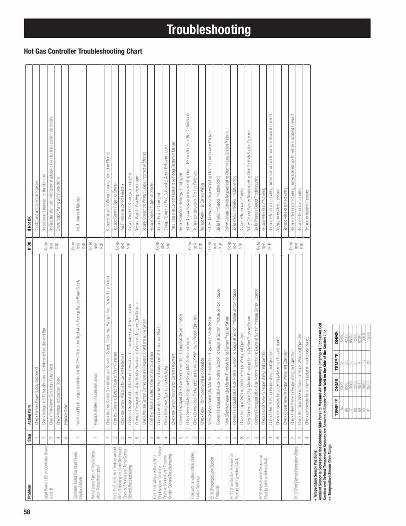
58
Troubleshooting
Hot Gas Controller Troubleshooting Chart
Prob
lem
Step
Actio
n Ite
mIf
OKIf
Not O
K
Inpu
t Pow
er L
ED o
n Co
ntro
ller B
oard
is
not l
it
1Ch
eck
Prim
ary
Powe
r Sup
ply
Disc
onne
ct
Go to
ne
xt
step
Chec
k fu
ses
and/
or c
ircui
t bre
aker
s
2Ch
eck
Volta
ge to
24V
tran
sfor
mer
s in
Con
dens
ing
Unit
Elec
trica
l Box
Re-s
et c
ircui
t bre
aker
(s) o
n tra
nsfo
rmer
s
3Ch
eck
Tran
sfor
mer
Sec
onda
ry O
utpu
t Vol
tsRe
plac
e tra
nsfo
rmer
s if
nece
ssar
y, if
volta
ge is
low,
che
ck ta
p po
sitio
n on
prim
ary
4Ch
eck
Volta
ge to
Con
trolle
r Boa
rdCh
eck
fact
ory
Wirin
g an
d Co
nnec
tions
5Re
plac
e Bo
ard
Cont
rolle
r Boa
rd h
as In
put P
ower
, Di
splay
is B
lank
1Ve
rify
that
Blac
k Ju
mpe
r Is
Inst
alled
on
“Pic
Pwr”
Pins
to th
e Ri
ght o
f the
Bac
kup
Batte
ry P
ower
Sup
ply
Go to
ne
xt
step
Inst
all J
umpe
r if M
issin
g
Boar
d Lo
ses
Tim
e of
Day
Set
tings
wh
en P
ower
Inte
rrupt
ed1
Repl
ace
Batte
ry o
n Co
ntro
ller B
oard
Go to
ne
xt
step
Err1
, Err2
, Err6
, Err7
(with
or w
ithou
t Al
r1) D
isplay
ing
on C
ontro
ller S
enso
r Op
en o
r Sho
rted-
and-
Tem
p Se
nsor
Ge
nera
l Tro
uble
shoo
ting
1Ch
eck
that
the
Sens
or C
onne
ctio
ns a
re S
ecur
e at
Boa
rd; C
heck
Fie
ld W
iring
if Ev
ap D
efro
st Te
mp
Sens
or
Go to
ne
xt
step
Secu
re, C
orre
ct th
e W
iring
if Lo
ose,
Inco
rrect
or S
horte
d
2Oh
m th
e Se
nsor
to D
etec
t Ope
n or
Sho
rt Co
nditio
nRe
plac
e Se
nsor
if O
pen
or S
horte
d
3Ch
eck
the
Sens
or P
ositio
ns fo
r Cor
rect
Plac
emen
t Pl
ace
Sens
or in
Cor
rect
Pos
ition+
4Co
mpa
re D
isplay
ed V
alue
(Use
Mon
itor F
unct
ion)
to T
herm
omet
er a
t Sen
sor L
ocat
ion
Repl
ace
Sens
or if
Rea
ding
s do
not
agr
ee
5Co
mpa
re D
isplay
ed V
alue
(Use
Mon
itor F
unct
ion)
to R
efer
ence
Tem
p on
Ohm
Tabl
e++
Repl
ace
Boar
d if
Read
ings
do
not a
gree
Err4
, Err5
(with
or w
ithou
t Alr1
) Di
splay
ing
on C
ontro
ller
Sen
sor
Open
or S
horte
d-an
d-Pr
essu
re
Sens
or G
ener
al Tr
oubl
esho
otin
g
1Ch
eck
that
the
Sens
or C
onne
ctio
ns a
re S
ecur
e at
Boa
rd a
nd a
t the
Sen
sor
Go to
ne
xt
step
Secu
re, C
orre
ct th
e W
iring
if Lo
ose,
Inco
rrect
or S
horte
d
2Oh
m th
e Se
nsor
to D
etec
t Ope
n or
Sho
rt Co
nditio
nRe
plac
e Se
nsor
if O
pen
or S
horte
d
3Ch
eck
Cont
rolle
r Boa
rd fo
r Sho
rted
Com
pone
nts
if Se
nsor
was
Sho
rted
Repl
ace
Boar
d if
Dam
aged
4Ch
eck
Refri
gera
nt T
ype
In P
rogr
am M
enu
Chan
ge R
efrig
eran
t Typ
e Se
lect
ed to
Act
ual R
efrig
eran
t Use
d
5Ch
eck
the
Sens
or P
ositio
ns fo
r Cor
rect
Plac
emen
tPl
ace
Sens
or in
Cor
rect
Pos
ition
(see
Pip
ing
Diag
ram
in M
anua
l)
6Co
mpa
re D
isplay
ed V
alue
(Use
Mon
itor F
unct
ion)
to G
auge
at S
enso
r Loc
atio
nRe
plac
e Se
nsor
if R
eadi
ngs
do n
ot a
gree
Err9
(with
or w
ithou
t Alr3
) (Sa
fety
Ci
rcui
t Ope
ning
)
1Ch
eck
Serv
iceM
ate
Stat
us a
nd S
ervic
eMat
e Re
fere
nce
Guid
eGo
to
next
st
ep
Follo
w Ge
nera
l Sys
tem
Trou
bles
hoot
ing
Char
t, LP
S Fu
nctio
n is
on th
e Co
ntro
l Boa
rd
2Ch
eck
Com
pres
sor C
onta
ctor
(s) a
nd A
uxilia
ry S
witc
h(es
) for
Pro
per O
pera
tion
Repl
ace
cont
acto
r(s) o
r Aux
iliary
Swi
tch(
es)
3Ch
eck
Relay
1 fo
r Pro
per W
iring
and
Oper
atio
nRe
plac
e Re
lay 1
or C
orre
ct W
iring
Er10
(Pro
long
ed L
ow S
uctio
n Pr
essu
re)
1Vi
ew D
isplay
ed V
alue
(Use
Mon
itor F
unct
ion)
for t
he S
uctio
n Pr
essu
re S
enso
rGo
to
next
st
ep
Follo
w Ge
nera
l Sys
tem
Trou
bles
hoot
ing
Char
t for
Low
Suc
tion
Pres
sure
2Co
mpa
re D
isplay
ed V
alue
(Use
Mon
itor F
unct
ion)
to G
auge
at S
uctio
n Pr
essu
re S
enso
r Loc
atio
nGo
To P
ress
ure
Sens
or Tr
oubl
esho
otin
g
Er 1
1 (L
ow S
uctio
n Pr
essu
re a
t St
artu
p) (w
ith o
r with
out A
lr4)
1Vi
ew D
isplay
ed V
alue
(Use
Mon
itor F
unct
ion)
for t
he S
uctio
n Pr
essu
re S
enso
rGo
to
next
st
ep
Follo
w Ge
nera
l Sys
tem
Trou
bles
hoot
ing
Char
t for
Low
Suc
tion
Pres
sure
2Co
mpa
re D
isplay
ed V
alue
(Use
Mon
itor F
unct
ion)
to G
auge
at S
uctio
n Pr
essu
re S
enso
r Loc
atio
nGo
To P
ress
ure
Sens
or Tr
oubl
esho
otin
g
3Ch
eck
the
Liqu
id S
olen
oid
Valve
for P
rope
r Wirin
g an
d Op
erat
ion
Repl
ace
valve
or c
orre
ct w
iring
Er12
(Hig
h Su
ctio
n Pr
essu
re a
t St
artu
p) (w
ith o
r with
out A
lr4)
1Vi
ew D
isplay
ed V
alue
(Use
Mon
itor F
unct
ion)
for t
he S
uctio
n Pr
essu
re S
enso
r
Go to
ne
xt
step
Follo
w Ge
nera
l Sys
tem
Trou
bles
hoot
ing
Char
t for
Hig
h Su
ctio
n Pr
essu
re
2Co
mpa
re D
isplay
ed V
alue
(Use
Mon
itor F
unct
ion)
to G
auge
at S
uctio
n Pr
essu
re S
enso
r Loc
atio
nGo
To P
ress
ure
Sens
or Tr
oubl
esho
otin
g
3Ch
eck
Bypa
ss V
alve
for P
rope
r Wirin
g an
d Op
erat
ion
Repl
ace
valve
or c
orre
ct w
iring
4Ch
eck
Defro
st V
alve
for P
rope
r Wirin
g an
d Op
erat
ion
Repl
ace
valve
or c
orre
ct w
iring
, mak
e su
re m
anua
l lift
feat
ure
is di
sabl
ed if
pre
sent
5Ch
eck
com
pres
sor f
or p
robl
ems
(valv
e or
runn
ing
gear
issu
es)
Repl
ace
or re
pair
com
pres
sor
Er13
(Pos
t Def
rost
Pum
pdow
n Er
ror)
1Ch
eck
Bypa
ss V
alve
for P
rope
r Wirin
g an
d Op
erat
ion
Go to
ne
xt
step
Repl
ace
valve
or c
orre
ct w
iring
2Ch
eck
Defro
st V
alve
for P
rope
r Wirin
g an
d Op
erat
ion
Repl
ace
valve
or c
orre
ct w
iring
, mak
e su
re m
anua
l lift
feat
ure
is di
sabl
ed if
pre
sent
3Ch
eck
the
Liqu
id S
olen
oid
Valve
for P
rope
r Wirin
g an
d Op
erat
ion
Repl
ace
valve
or c
orre
ct w
iring
4Ch
eck
com
pres
sor f
or p
robl
ems
(valv
e or
runn
ing
gear
issu
es)
Repl
ace
or re
pair
com
pres
sor
+ T
empe
ratu
re S
enso
r Pos
ition
s: A
mbi
ent S
enso
r is
Secu
red
on th
e Co
nden
ser S
ide
Pane
l to
Mea
sure
Air
Tem
pera
ture
Ent
erin
g #1
Con
dens
er C
ell
Suc
tion
and
Defr
ost T
empe
ratu
re S
enso
rs a
re S
ecur
ed in
Cop
per S
enso
r Wel
l on
the
Side
of t
he S
uctio
n Li
ne+
+ T
empe
ratu
re S
enso
r Ohm
Ran
ge
TE
MP
ºF
OH
MS
TE
MP
ºF
OH
MS
104
5320
3232
650
8680
6023
4233
077
1000
014
5533
068
1249
05
7295
059
1571
0-4
9707
050
1990
0-1
313
0410
4125
400
-22
1769
60

59
Troubleshooting
SYMPTOMS POSSIBLE CAUSES POSSIBLE CORRECTIVE STEPS Fan(s) will not operate 1. Main switch open 1. Close switch 2. Blown fuses 2. Replace fuses. Check for short circuits or overload conditions 3. Defective motor 3. Replace motor 4. Defective timer or defrost thermostat 4. Replace defective component 5. Unit in defrost cycle 5. Wait for completion of cycle
Room temperature too high 1. Room thermostat set too high 1. Adjust thermostat 2. Superheat too high 2. Adjust thermal expansion valve 3. System low on refrigerant 3. Add refrigerant 4. Coil iced-up 4. Manually defrost coil. Check defrost controls for malfunction 5. Unit cooler located too close to doors 5. Relocate unit cooler or add strip curtain to door opening 6. Heavy air infiltration 6. Seal unwanted openings in room
Ice accumulating on ceiling 1. Defrost duration is too long 1. Adjust defrost termination settings around evaporator and/or on 2. Defective defrost thermostat or timer 2. Replace defective component fan guards venturi or blades 3. Too many defrosts 3. Reduce number of defrosts
Coil not clearing of frost during 1. Coil temperature not getting above 1. Check heater operation defrost cycle freezing point during defrost 2. Not enough defrost cycles per day 2. Adjust controller for more defrost cycles 3. Defrost cycle too short 3. Adjust defrost settings for longer cycle 4. Defective timer or defrost thermostat 4. Replace defective component
Ice accumulating in drain pan 1. Defective heater 1. Replace heater 2. Unit not pitched properly 2. Check and adjust if necessary 3. Drain line plugged 3. Clean drain line 4. Defective drain line heater 4. Replace heater 5. Defective timer or thermostat 5. Replace defective component
Uneven coil frosting 1. Located too close to door or opening 1. Relocate evaporator 2. Defrost termination set too low 2. Adjust defrost termination setting higher. 3. Incorrect or missing distributor nozzle 3. Add or replace nozzle with appropriately sized orifice for conditions.
General Evaporator Troubleshooting Chart

60
Troubleshooting
PROBLEM POSSIBLE CAUSES POSSIBLE CORRECTIVE STEPS Compressor will not run 1. Main switch open. 1. Close switch. 2. Fuse blown. 2. Check electrical circuits and motor winding for shorts or grounds Investigate for possible overloading. Replace fuse after fault is corrected. 3. Thermal overloads tripped. 3. Overloads are automatically reset. Check unit closely when
unit comes back on line. 4. Defective contactor or coil. 4. Repair or replace. 5. System shut down by safety devices. 5. Determine type and cause of shutdown and correct it before
resetting safety switch.
6. No cooling required. 6. None. Wait until calls for cooling. 7. Liquid line solenoid will not open. 7. Repair or replace coil. 8. Motor electrical trouble. 8. Check motor for open windings, short circuit or burn out. 9. Loose wiring. 9. Check all wire junctions. Tighten all terminal screws. 10. Phase loss monitor inoperative. 10. Refer to page 24.
Compressor noisy or vibrating 1. Flooding of refrigerant into crankcase. 1. Check setting of expansion valves. 2. Improper piping support on suction or 2. Relocate, add or remove hangers. liquid line. 3. Worn compressor. 3. Replace. .
High discharge pressure 1. Non-condensables in system. 1. Remove the non-condensables. 2. System overcharges with refrigerant. 2. Remove excess. 3. Discharge shutoff valve partially closed. 3. Open valve. 4. Fan not running. 4. Check electrical circuit. 5. Head pressure control setting. 5. Adjust. 6. Dirty condenser coil. 6. Clean.
Low discharge pressure 1. Faulty condenser temperature regulation. 1. Check condenser control operation. 2. Suction shutoff valve partially closed. 2. Open valve. 3. Insufficient refrigerant in system. 3. Check for leaks. Repair and add charge. 4. Low suction pressure. 4. See corrective steps for low suction pressure. 5. Variable head pressure valve. 5. Check valve setting.
High suction pressure 1. Excessive load. 1. Reduce load or add additional equipment. 2. Expansion valve overfeeding. 2. Check remote bulb. Regulate superheat.
Low suction pressure 1. Lack of refrigerant. 1. Check for leaks. Repair and add charge. 2. Evaporator dirty or iced. 2. Clean. 3. Clogged liquid line filter drier. 3. Replace cartridge(s). 4. Clogged suction line or compressor 4. Clean strainers. suction gas strainers. 5. Expansion valve malfunctioning. 5. Check and reset for proper superheat. 6. Condensing temperature too low. 6. Check means for regulating condensing temperature. 7. Improper TXV. 7. Check for proper sizing.
Little or no oil pressure 1. Clogged suction oil strainer. 1. Clean. 2. Excessive liquid in crankcase. 2. Check crankcase heater. Reset expansion valve for higher
superheat. Check liquid line solenoid valve operation. 3. Low oil pressure safety switch defective. 3. Replace. 4. Worn oil pump. 4. Replace. 5. Oil pump reversing gear stuck in wrong 5. Reverse direction of compressor rotation. position. 6. Worn bearings. 6. Replace compressor. 7. Low oil level. 7. Add oil and/or through defrost. 8. Loose fitting on oil lines. 8. Check and tighten system. 9. Pump housing gasket leaks. 9. Replace gasket.
Compressor loses oil 1. Lack of refrigerant. 1. Check for leaks and repair. Add refrigerant. 2. Excessive compression ring blow by. 2. Replace compressor. 3. Refrigerant flood back. 3. Maintain proper superheat at compressor. 4. Improper piping or traps. 4. Correct piping.
Compressor thermal protector switch open 1. Operating beyond design conditions. 1. Add components to bring conditions within acceptable limits (Consult Heatcraft)
2. Discharge valve partially shut. 2. Open valve. 3. Blown valve plate gasket. 3. Replace gasket. 4. Dirty condenser coil. 4. Clean coil. 5. Overcharged system. 5. Reduce charge.
General System Troubleshooting Chart

61
Preventive MaintenanceUnit CoolersAt every six month interval, or sooner if local conditions cause clogging or fouling of air passages through the finned surface, the following items should be checked.
1) Visually inspect unit
• Look for signs of corrosion on fins, cabinet, copper tubing and solder joints.
• Look for excessive or unusual vibration for fan blades or sheet metal panels when in operation. Identify fan cell(s) causing vibration and check motor and blade carefully.
• Look for oil stains on headers, return bends, and coil fins. Check any suspect areas with an electronic leak detector.
• Check drain pan to insure that drain is clear of debris, obstructions or ice buildup and is free draining.
2) Clean evaporator coil and blades
• Periodic cleaning can be accomplished by using a brush, pressurized water or a commercially available evaporator
coil cleaner or mild detergent. Never use an acid based cleaner. Follow label directions for appropriate use. Be sure the product you use is approved for use in your particular application.
• Flush and rinse coil until no residue remains.
• Pay close attention to drain pan, drain line and trap.
3) Check the operation of all fans and ensure airflow is unobstructed
• Check that each fan rotates freely and quietly. Replace any fan motor that does not rotate smoothly or makes an unusual noise.
• Check all fan set screws and tighten if needed.
• Check all fan blades for signs of stress or wear. Replace any blades that are worn, cracked or bent.
• Verify that all fan motors are securely fastened to the motor rail.
• Lubricate motors if applicable.
4) Inspect electrical wiring and components
• Visually inspect all wiring for wear, kinks, bare areas and discoloration. Replace any wiring found to be damaged.
• Verify that all electrical and ground connections are secure, tighten if necessary.
• Check operation/calibration of all fan cycle and defrost controls when used.
• Look for abnormal accumulation of ice patterns and adj ust defrost cycles accordingly
• Compare actual defrost heater amp draw against unit data plate.
• Check drain line heat tape for proper operation (supplied and installed by others).
5) Refrigeration Cycle
• Check unit cooler superheat and compare reading for your specific application
• Visually inspect coil for even distribution
Air Cooled Condensing Units
Quarterly
1) Visually inspect unit
• Look for signs of oil stains on interconnection piping and condenser coil. Pay close attention to areas around solder joints, building penetrations and pipe clamps. Check any suspect areas with an electronic leak detector. Repair any leaks found and add refrigerant as needed.
• Check condition of moisture indicator/sightglass in the sight glass if so equipped. Replace liquid line drier if there is indication of slight presence of moisture. Replace refrigerant, oil and drier if moisture concentration is indicated to be high.
• Check moisture indicator/sightglass for flash gas. If found check entire system for refrigerant leaks and add refrigerant as needed after repairing any leaks.
• Check compressor sightglass (if equipped) for proper oil level.
• Check condition of condenser. Look for accumulation of dirt and debris (clean as required).
• Check for unusual noise or vibration. Take corrective action as required.
• Inspect wiring for signs of wear or discoloration and repair if needed.
• Check and tighten all flare connections. Semi-Annually
2) Repeat all quarterly inspection items.
3) Clean condenser coil and blades • Periodic cleaning can be accomplished by using a brush, pressurized water and a commercially available foam coil cleaner. If foam cleaner is used, it should not be an acid based cleaner. Follow label directions for appropriate use.
• Rinse until no residue remains.
4) Check operation of condenser fans • Check that each fan rotates freely and quietly. Replace any fan motor that does not rotate smoothly or makes excessive noise.
• Check all fan blade set screws and tighten as required.
• Check all fan blades for signs of cracks, wear or stress. Pay close attention to the hub and spider. Replace blades as required.
• Verify that all motors are mounted securely.
• Lubricate motors if applicable. Do not lubricate permanently sealed, ball bearing motors.

62
Semi-Annually (cont.)
5) Inspect electrical wiring and components
• Verify that all electrical and ground connections are secure, tighten as required.
• Check condition of compressor and heater contactors.
Look for discoloration and pitting. Replace as required.
• Check operation and calibration of all timers, relays pressure controls and safety controls.
• Clean electrical cabinet. Look for signs of moisture, dirt, debris, insects and wildlife. Take corrective action as required.
• Verify operation of crankcase heater by measuring amp draw.
6) Check refrigeration cycle
• Check suction, discharge and net oil pressure readings. If abnormal take appropriate action.
• Check pressure drop across all filters and driers. Replace as required.
• Verify that superheat at the compressor conforms to specification. (See page 54)
• Check pressure and safety control settings and verify proper operation.
Preventive MaintenanceAnnually
7) In addition to quarterly and semiannual maintenance checks, submit an oil sample for analysis
• Look for high concentrations of acid or moisture. Change oil and driers until test results read normal.
• Investigate source of high metal concentrations, which normally are due to abnormal bearing wear. Look for liquid refrigerant in the crankcase, low oil pressure or low superheat as a possible source.
8) Inspect suction accumulator (if equipped)
• If the accumulator is insulated remove insulation and inspect for leaks and corrosion.
• Pay close attention to all copper to steel brazed connections
• Wire brush all corroded areas and peeling paint.
• Apply an anticorrosion primer and paint as required. Re-insulate if applicable.
• Check accuracy of the suction line temperature and pressure sensors before the suction accumulator by comparing the controller reading in the monitor mode to a thermometer and pressure gauge of known accuracy

63
ELECTRICAL PARTS
DescriptionPart Num-
ber
Hot Gas Control Board 28910302
Transformer 100VA 24V - 208/230V 22555601
Electronic Pressure Regulator+ 29326701
Pressure Regulator Harness+ 22592201
Suction Pressure Transducer (0-300 PSIA) 28911202
Suction Transducer Harness (Blue) 22515102
Liquid Pressure Transducer (0-500 PSIA) 28911203
Liquid Transducer Harness (Black) 22515103
Suction Temp Sensor (Blue) 28900310
Ambient /Room Temp Sensor (White 93" leads)
28900311
High Pressure Switch 28913201
Evaporator Sensor 28900108
Evaporator Contactor 30A 2252430
Evaporator Contactor 40A 2252440
Evap Liquid Solenoid 1/2” conn 29324201
Evap Liquid Solenoid 5/8” conn 29324301
Evap Liquid Solenoid 7/8” conn 29324401
Low Pressure Switch (Redundant) 2890099
Coil (Parker SC) 24V 22593201
InterLink Service Parts
CONDENSING UNIT PIPING COMPONENTS
CondensingUnit Model
3-Way Valve
Suction Stop
SolenoidValve
DefrostSolenoid
Valve
BypassSolenoid
Valve
AeroquipHose
0602L6 29323601 29330301 29321701 29324201 28991004
0752L6 29323601 29330301 29321701 29324201 28991004
0902L6 29323701 29330401 29321801 29324201 28991002
01002L6 29323701 29330401 29321801 29324201 28991002
01202L6 29323701 29330401 29321901 29324201 28991002
01502L6 29323701 29330402 29321901 29324301 28991002
2202L6 29323701 29330402 29330402 29324301 28991001
2702L6 29323801 29330403 29330402 29324301 28991009
3002L6 29323801 29330403 29330402 29324301 28991009
0752 M6 29323701 29330301 29321701 29324201 28991003
0762 M6 29323701 29330301 29321701 29324201 28991003
0802 M6 29323701 29330401 29321801 29324201 28991002
1002 M6 29323701 29330401 29321801 29324201 28991002
1202 M6 29323701 29330402 29321901 29324301 28991002
1502 M6 29323801 29330402 29321901 29324301 28991009
2002 M6 29323801 29330402 29321901 29324301 28991002
2502 M6 29323801 29330403 29330402 29324401 28991001
3002 M6 29323801 29330403 29330402 29324401 28991001
3502 M6 29323801 29330402 (2) 29330403 29324401 28991001
4002 M6 29323801 29330402 (2) 29330403 29324401 28991001
0752 M2 29323701 29330301 29321701 29324201 28991003
0762 M2 29323701 29330301 29321701 29324201 28991003
0802 M2 29323701 29330401 29321801 29324201 28991002
1002 M2 29323701 29330401 29321801 29324201 28991002
1202 M2 29323701 29330402 29321901 29324301 28991002
1502 M2 29323801 29330402 29321901 29324301 28991009
2002 M2 29323801 29330402 29321901 29324301 28991002
2502 M2 29323801 29330403 29330402 29324401 28991001
3002 M2 29323801 29330403 29330402 29324401 28991001
3502 M2 29323801 29330402 (2) 29330403 29324401 28991001
4002 M2 29323801 29330402 (2) 29330403 29324401 28991001
*Effective 2/15/12, production and service parts will use the 28910302 control board with V1.06 software which is backwards compatible with all previous versions. See Pages 65 for installation and wiring differences.+ Effective 11/1/11, production and service parts will use the 29326701 Carel pressure regulator and 22592201 harness. See Page 66 for valve identification and Page 63-64 for regulator program settings. V1.06 software is programmed for the Carel valve. Alco may be selected in Expert mode or the parameters may be programmed manually on the previous 28910301 control board.NOTE: for suction stop and defrost values use the following valve seal kits:Valve: HRP # 29330301 use Parker #204671Valve: HRP# 29330401,02,03 use Parker #204670
Hot Gas Defrost System Service PartsWhenever possible, replacement parts are to be obtained from a local wholesaler authorized to sell one of Heatcraft Refrigeration Products’ brands. Replacement parts which are covered under the terms of the warranty statement on page 6 of this manual, will be reimbursed for total part cost only. The original invoice from the parts supplier must accompany all warranty claims for replacement part reimbursement. Heatcraft Refrigeration Products reserves the right to adjust the compensation amount paid on any parts submitted for warranty reimbursement when a parts supplier’s original invoice is not provided with a claim. You may obtain information regarding local authorized wholesalers by calling the InterLink Service Parts Center at 1-800-686-7278 between the hours of 7:30 AM to 4:30 PM Central Time.

64
System Reference Data
The following information should be filled out and signed by Refrigeration Installation Contractor at time of start-up.
Date System Installed: _____________________________________________________
Installer and Address: _____________________________________________________
_____________________________________________________
_____________________________________________________
Condensing Unit Unit Model#: ________________________________________
Unit Serial #: ________________________________________
Compressor Model #: ____________________ Compressor Model #: _________________
Compressor Serial #: ____________________ Compressor Serial #: __________________ Electrical _________________ Volts __________________ Phase_______
Voltage at Compressor L1__________ L2 ___________ L3 ___________
Amperage at Compressor L1__________ L2 ___________ L3 ___________
Evaporator(s) Quantity ________________________________________
Evaporator Model #: ____________________ Evaporator Model #: __________________
Evaporator Serial #: ____________________ Evaporator Serial #: __________________
Electrical _________________ Volts __________________ Phase _______
Expansion Valve Manufacturer/Model ____________________ _______________________
Ambient at Start-Up _____________________________˚F
Design Box Temperature ______________________˚F _________________________˚F
Operating Box Temperature ______________________˚F __________________________˚F
Thermostat Setting ____________________________˚F __________________________˚F
Defrost Setting _____ / day ______ minutes fail-safe ______/day ______minutes fail-safe
Compressor Discharge Pressure _____________________PSIG ____________________PSIG
Compressor Suction Pressure _____________________PSIG ____________________PSIG
Suction Line Temperature @ Comp. ______________________˚F ______________________˚F
Discharge Line Temperature @ Comp. ____________________˚F ______________________˚F
Superheat at Compressor _____________________˚F ______________________˚F
Suction Line Temperature @ Evaporator ___________________˚F ______________________˚F
Superheat at Evaporator _____________________˚F ______________________˚F
Evacuation: # times _______ Final Micron_______ # Times ________ Final Micron_______
Evaporator Drain Line Trapped Outside of Box: yes no
A permanent data sheet should be prepared on each refrigeration system at an installation, with a copy for the owner and the original for the installing contractor's files.
If another firm is to handle service and maintenance, additional copies should be prepared as necessary.
Service Record

65
Factory Default Settings
MODEL REFRIG SIZE
Fan Cycle Settings (Liquid Pressure, PRES), psig DFT 1 CAREL ALCO
Fan 1 Fan 2 Fan 3 Fan 4 Fan 1 Fan 2 Fan 3 Fan 4 DFT 2 DEFP DEFT EQUT LPSH LPSL FZET FZTM
ON ON ON ON OFF OFF OFF OFF °F psig Min. Min. psig psig °F Min. PRFS PRFS PRUI DFIO
M2 R22752, 762
155 170 --- --- 110 145 --- --- 85 210 25 2 16 6 35 4 320 300 15 100
M2 R22 802 155 170 --- --- 110 145 --- --- 85 210 25 2 16 6 35 4 320 300 15 100
M2 R22 1002 155 170 --- --- 110 145 --- --- 85 210 25 2 16 6 35 4 350 320 15 100
M2 R22 1202 155 170 --- --- 110 145 --- --- 85 210 25 2 16 6 35 4 380 340 15 100
M2 R22 1502 155 170 --- --- 110 145 --- --- 85 210 25 2 16 6 35 4 410 380 15 100
M2 R22 2002 155 170 --- --- 110 145 --- --- 85 210 25 2 16 6 35 4 470 440 15 100
M2 R22 2502 155 170 180 --- 110 145 155 --- 85 210 25 2 16 6 35 4 510 520 17 100
M2 R22 3002 155 170 180 --- 110 145 155 --- 85 210 25 2 16 6 35 4 550 600 20 100
M2 R22 3502 155 170 180 --- 110 145 155 85 210 25 2 16 6 35 4 570 700 23 100
M2 R22 4002 155 170 180 195 110 145 155 170 85 210 25 2 16 6 35 4 590 780 25 100
M6 R404A752, 762
190 205 --- --- 135 175 --- --- 85 210 25 2 24 10 35 4 320 300 15 100
M6 R404A 802 190 205 --- --- 135 175 --- --- 85 210 25 2 24 10 35 4 320 300 15 100
M6 R404A 1002 190 205 --- --- 135 175 --- --- 85 210 25 2 24 10 35 4 350 320 15 100
M6 R404A 1202 190 205 --- --- 135 175 --- --- 85 210 25 2 24 10 35 4 380 340 15 100
M6 R404A 1502 190 205 --- --- 135 175 --- --- 85 210 25 2 24 10 35 4 410 380 15 100
M6 R404A 2002 190 205 --- --- 135 175 --- --- 85 210 25 2 24 10 35 4 470 440 15 100
M6 R404A 2502 190 205 220 --- 135 175 190 --- 85 210 25 2 24 10 35 4 510 520 17 100
M6 R404A 3002 190 205 220 --- 135 175 190 --- 85 210 25 2 24 10 35 4 550 600 20 100
M6 R404A 3502 190 205 220 --- 135 175 190 --- 85 210 25 2 24 10 35 4 570 700 23 100
M6 R404A 4002 190 205 220 235 135 175 190 205 85 210 25 2 24 10 35 4 590 780 25 100
M6 R507752, 762
195 210 --- --- 140 180 --- --- 85 210 25 2 26 11 35 4 320 300 15 100
M6 R507 802 195 210 --- --- 140 180 --- --- 85 210 25 2 26 11 35 4 320 300 15 100
M6 R507 1002 195 210 --- --- 140 180 --- --- 85 210 25 2 26 11 35 4 350 320 15 100
M6 R507 1202 195 210 --- --- 140 180 --- --- 85 210 25 2 26 11 35 4 380 340 15 100
M6 R507 1502 195 210 --- --- 140 180 --- --- 85 210 25 2 26 11 35 4 410 380 15 100
M6 R507 2002 195 210 --- --- 140 180 --- --- 85 210 25 2 26 11 35 4 470 440 15 100
M6 R507 2502 195 210 225 --- 140 180 195 --- 85 210 25 2 26 11 35 4 510 520 17 100
M6 R507 3002 195 210 225 --- 140 180 195 --- 85 210 25 2 26 11 35 4 550 600 20 100
M6 R507 3502 195 210 225 --- 140 180 195 --- 85 210 25 2 26 11 35 4 570 700 23 100
M6 R507 4002 195 210 225 245 140 180 195 210 85 210 25 2 26 11 35 4 590 780 25 100
M6 R407A752, 762
190 205 --- --- 135 175 --- --- 85 210 25 2 15 3 35 4 320 300 15 100
M6 R407A 802 190 205 --- --- 135 175 --- --- 85 210 25 2 15 3 35 4 320 300 15 100
M6 R407A 1002 190 205 --- --- 135 175 --- --- 85 210 25 2 15 3 35 4 350 320 15 100
M6 R407A 1202 190 205 --- --- 135 175 --- --- 85 210 25 2 15 3 35 4 380 340 15 100
M6 R407A 1502 190 205 --- --- 135 175 --- --- 85 210 25 2 15 3 35 4 410 380 15 100
M6 R407A 2002 190 205 --- --- 135 175 --- --- 85 210 25 2 15 3 35 4 470 440 15 100
M6 R407A 2502 190 205 220 --- 135 175 190 --- 85 210 25 2 15 3 35 4 510 520 17 100
M6 R407A 3002 190 205 220 --- 135 175 190 --- 85 210 25 2 15 3 35 4 550 600 20 100
M6 R407A 3502 190 205 220 --- 135 175 190 --- 85 210 25 2 15 3 35 4 570 700 23 100

66
Factory Default Settings
MODEL REFRIG SIZE
Fan Cycle Settings (Liquid Pressure, PRES) , psig DFT 1 CAREL ALCO
Fan 1 Fan 2 Fan 3 Fan 4 Fan 1 Fan 2 Fan 3 Fan 4 DFT 2 DEFP DEFT EQUT LPSH LPSL FZET FZTM
ON ON ON ON OFF OFF OFF OFF °F psig Min. Min. psig psig °F Min. PRFS PRFS PRUI DFIO
M6 R407A 4002 190 205 220 235 135 175 190 205 85 210 25 2 15 3 35 4 590 780 25 100
M6 R407C752, 762
180 195 --- --- 130 165 --- --- 85 210 25 2 12 1 35 4 320 300 15 100
M6 R407C 802 180 195 --- --- 130 165 --- --- 85 210 25 2 12 1 35 4 320 300 15 100
M6 R407C 1002 180 195 --- --- 130 165 --- --- 85 210 25 2 12 1 35 4 350 320 15 100
M6 R407C 1202 180 195 --- --- 130 165 --- --- 85 210 25 2 12 1 35 4 380 340 15 100
M6 R407C 1502 180 195 --- --- 130 165 --- --- 85 210 25 2 12 1 35 4 410 380 15 100
M6 R407C 2002 180 195 --- --- 130 165 --- --- 85 210 25 2 12 1 35 4 470 440 15 100
M6 R407C 2502 180 195 210 --- 130 165 180 --- 85 210 25 2 12 1 35 4 510 520 17 100
M6 R407C 3002 180 195 210 --- 130 165 180 --- 85 210 25 2 12 1 35 4 550 600 20 100
M6 R407C 3502 180 195 210 --- 130 165 180 --- 85 210 25 2 12 1 35 4 570 700 23 100
M6 R407C 4002 180 195 210 225 130 165 180 195 85 210 25 2 12 1 35 4 590 780 25 100
M6 R407F752, 762
200 215 --- --- 145 185 --- --- 85 215 25 2 16 4 35 4 320 300 15 100
M6 R407F 802 200 215 --- --- 145 185 --- 85 215 25 2 16 4 35 4 320 300 15 100
M6 R407F 1002 200 215 --- --- 145 185 --- --- 85 215 25 2 16 4 35 4 350 320 15 100
M6 R407F 1202 200 215 --- --- 145 185 --- --- 85 215 25 2 16 4 35 4 380 340 15 100
M6 R407F 1502 200 215 --- --- 145 185 --- --- 85 215 25 2 16 4 35 4 410 380 15 100
M6 R407F 2002 200 215 --- --- 145 185 --- --- 85 215 25 2 16 4 35 4 470 440 15 100
M6 R407F 2502 200 215 230 --- 145 185 200 --- 85 215 25 2 16 4 35 4 510 520 17 100
M6 R407F 3002 200 215 230 --- 145 185 200 --- 85 215 25 2 16 4 35 4 550 600 20 100
M6 R407F 3502 200 215 230 --- 145 185 200 --- 85 215 25 2 16 4 35 4 570 700 23 100
M6 R407F 4002 200 215 230 250 145 185 200 215 85 215 25 2 16 4 35 4 590 780 25 100
L6 R404A 602 190 205 --- --- 135 175 --- --- 75 180 25 2 10 2 30 4 320 300 15 100
L6 R404A 752 190 205 --- --- 135 175 --- --- 75 180 25 2 10 2 30 4 350 320 15 100
L6 R404A 902 190 205 --- --- 135 175 --- --- 75 180 25 2 10 2 30 4 400 360 15 100
L6 R404A 1002 190 205 --- --- 135 175 --- --- 75 180 25 2 10 2 30 4 410 380 15 100
L6 R404A 1202 190 205 --- --- 135 175 --- --- 75 180 25 2 10 2 30 4 450 420 15 100
L6 R404A 1502 190 205 --- --- 135 175 --- --- 75 180 25 2 10 2 30 4 480 460 16 100
L6 R404A 2202 190 205 --- --- 135 175 --- --- 75 180 25 2 10 2 30 4 540 580 19 100
L6 R404A 2702 190 205 --- --- 135 175 --- --- 75 180 25 2 10 2 30 4 560 660 22 100
L6 R404A 3002 190 205 --- --- 135 175 --- --- 75 180 25 2 10 2 30 4 580 720 23 100
L6 R507 602 195 210 --- --- 140 180 --- --- 75 180 25 2 11 2 30 4 320 300 15 100
L6 R507 752 195 210 --- --- 140 180 --- --- 75 180 25 2 11 2 30 4 350 320 15 100
L6 R507 902 195 210 --- --- 140 180 --- --- 75 180 25 2 11 2 30 4 400 360 15 100
L6 R507 1002 195 210 --- --- 140 180 --- --- 75 180 25 2 11 2 30 4 410 380 15 100
L6 R507 1202 195 210 --- --- 140 180 --- --- 75 180 25 2 11 2 30 4 450 420 15 100
L6 R507 1502 195 210 --- --- 140 180 --- --- 75 180 25 2 11 2 30 4 480 460 16 100
L6 R507 2202 195 210 --- --- 140 180 --- --- 75 180 25 2 11 2 30 4 540 580 19 100
L6 R507 2703 195 210 --- --- 140 180 --- --- 75 180 25 2 11 2 30 4 560 660 22 100
L6 R507 3002 195 210 --- --- 140 180 --- --- 75 180 25 2 11 2 30 4 580 720 23 100

67
Factory Default Settings
MODEL REFRIG SIZE
Fan Cycle Settings (Liquid Pressure, PRES) , psig DFT 1 CAREL ALCO
Fan 1 Fan 2 Fan 3 Fan 4 Fan 1 Fan 2 Fan 3 Fan 4 DFT 2 DEFP DEFT EQUT LPSH LPSL FZET FZTM
ON ON ON ON OFF OFF OFF OFF °F psig Min. Min. psig psig °F Min. PRFS PRFS PRUI DFIO
M6 R448A752,762
195 210 --- --- 140 180 --- --- 85 215 25 2 26 10 35 4 320 300 15 100
M6 R448A 802 195 210 --- --- 140 180 --- --- 85 215 25 2 26 10 35 4 320 300 15 100
M6 R448A 1002 195 210 --- --- 140 180 --- --- 85 215 25 2 26 10 35 4 320 300 15 100
M6 R448A 1202 195 210 --- --- 140 180 --- --- 85 215 25 2 26 10 35 4 350 320 15 100
M6 R448A 1502 195 210 --- --- 140 180 --- --- 85 215 25 2 26 10 35 4 380 340 15 100
M6 R448A 2002 195 210 --- --- 140 180 --- --- 85 215 25 2 26 10 35 4 410 380 15 100
M6 R448A 2502 195 210 225 --- 140 180 195 --- 85 215 25 2 26 10 35 4 470 440 17 100
M6 R448A 3002 195 210 225 --- 140 180 195 --- 85 215 25 2 26 10 35 4 510 520 20 100
M6 R448A 3502 195 210 225 --- 140 180 195 --- 85 215 25 2 26 10 35 4 550 600 23 100
M6 R448A 4002 195 210 225 240 140 180 195 210 85 215 25 2 26 10 35 4 570 700 25 100
M6 R449A752762
195 210 --- --- 140 180 --- --- 85 215 25 2 26 10 35 4 590 780 15 100
M6 R449A 802 195 210 --- --- 140 180 --- --- 85 215 25 2 26 10 35 4 320 300 15 100
M6 R449A 1002 195 210 --- --- 140 180 --- 85 215 25 2 26 10 35 4 320 300 15 100
M6 R449A 1202 195 210 --- --- 140 180 --- --- 85 215 25 2 26 10 35 4 350 320 15 100
M6 R449A 1502 195 210 --- --- 140 180 --- --- 85 215 25 2 26 10 35 4 380 340 15 100
M6 R449A 2002 195 210 --- --- 140 180 --- --- 85 215 25 2 26 10 35 4 410 380 15 100
M6 R449A 2502 195 210 225 --- 140 180 195 --- 85 215 25 2 26 10 35 4 470 440 17 100
M6 R449A 3002 195 210 225 --- 140 180 195 --- 85 215 25 2 26 10 35 4 510 520 20 100
M6 R449A 3502 195 210 225 --- 140 180 195 --- 85 215 25 2 26 10 35 4 550 600 23 100
M6 R449A 4002 195 210 225 240 140 180 195 210 85 215 25 2 26 10 35 4 570 700 25 100
L6 R448A 602 195 210 --- --- 140 180 --- --- 75 215 25 2 26 2 30 4 590 780 15 100
L6 R448A 752 195 210 --- --- 140 180 --- --- 75 215 25 2 10 2 30 4 320 300 15 100
L6 R448A 902 195 210 --- --- 140 180 --- --- 75 215 25 2 10 2 30 4 350 320 15 100
L6 R448A 1002 195 210 --- --- 140 180 --- --- 75 215 25 2 10 2 30 4 400 360 15 100
L6 R448A 1202 195 210 --- --- 140 180 --- --- 75 215 25 2 10 2 30 4 410 380 15 100
L6 R448A 1502 195 210 --- --- 140 180 --- --- 75 215 25 2 10 2 30 4 450 420 16 100
L6 R448A 2202 195 210 --- --- 140 180 --- --- 75 215 25 2 10 2 30 4 480 460 19 100
L6 R448A 2702 195 210 --- --- 140 180 --- --- 75 215 25 2 10 2 30 4 540 580 22 100
L6 R448A 3002 195 210 --- --- 140 180 --- --- 75 215 25 2 10 2 30 4 560 660 23 100
L6 R449A 602 195 210 --- --- 140 180 --- --- 75 215 25 2 10 2 30 4 580 720 15 100
L6 R449A 752 195 210 --- --- 140 180 --- --- 75 215 25 2 10 2 30 4 320 300 15 100
L6 R449A 902 195 210 --- --- 140 180 --- --- 75 215 25 2 10 2 30 4 350 320 15 100
L6 R449A 1002 195 210 --- --- 140 180 --- --- 75 215 25 2 10 2 30 4 400 360 15 100
L6 R449A 1202 195 210 --- --- 140 180 --- --- 75 215 25 2 10 2 30 4 410 380 15 100
L6 R449A 1502 195 210 --- --- 140 180 --- --- 75 215 25 2 10 2 30 4 450 420 16 100
L6 R449A 2202 195 210 --- --- 140 180 --- --- 75 215 25 2 10 2 30 4 480 460 19 100
L6 R449A 2702 195 210 --- --- 140 180 --- --- 75 215 25 2 10 2 30 4 540 580 22 100
L6 R449A 3002 195 210 --- --- 140 180 --- --- 75 215 25 2 10 2 30 4 560 660 23 100
L6 R407A 602 190 205 --- --- 135 175 --- --- 75 210 25 2 7 0 30 4 580 720 15 100
L6 R407A 752 190 205 --- --- 135 175 --- --- 75 210 25 2 7 0 30 4 320 300 15 100
L6 R407A 902 190 205 --- --- 135 175 --- --- 75 210 25 2 7 0 30 4 350 320 15 100

68
Factory Default Settings
MODEL REFRIG SIZE
Fan Cycle Settings (Liquid Pressure, PRES) , psig DFT 1 CAREL ALCO
Fan 1 Fan 2 Fan 3 Fan 4 Fan 1 Fan 2 Fan 3 Fan 4 DFT 2 DEFP DEFT EQUT LPSH LPSL FZET FZTM
ON ON ON ON OFF OFF OFF OFF °F psig Min. Min. psig psig °F Min. PRFS PRFS PRUI DFIO
L6 R407A 1002 190 205 --- --- 135 175 --- --- 75 210 25 2 7 0 30 4 410 380 15 100
L6 R407A 1202 190 205 --- --- 135 175 --- --- 75 210 25 2 7 0 30 4 450 420 15 100
L6 R407A 1502 190 205 --- --- 135 175 --- --- 75 210 25 2 7 0 30 4 480 460 16 100
L6 R407A 2202 190 205 --- --- 135 175 --- --- 75 210 25 2 7 0 30 4 540 580 19 100
L6 R407A 2702 190 205 --- --- 135 175 --- --- 75 210 25 2 7 0 30 4 560 660 22 100
L6 R407A 3002 190 205 --- --- 135 175 --- --- 75 210 25 2 7 0 30 4 580 720 23 100
L6 R407C 602 180 195 --- --- 130 165 --- --- 75 210 25 2 7 0 30 4 320 300 15 100
L6 R407C 752 180 195 --- --- 130 165 --- --- 75 210 25 2 7 0 30 4 350 320 15 100
L6 R407C 902 180 195 --- --- 130 165 --- --- 75 210 25 2 7 0 30 4 400 360 15 100
L6 R407C 1002 180 195 --- --- 130 165 --- --- 75 210 25 2 7 0 30 4 410 380 15 100
L6 R407C 1202 180 195 --- --- 130 165 --- --- 75 210 25 2 7 0 30 4 450 420 15 100
L6 R407C 1502 180 195 --- --- 130 165 --- --- 75 210 25 2 7 0 30 4 480 460 16 100
L6 R407C 2202 180 195 --- --- 130 165 --- --- 75 210 25 2 7 0 30 4 540 580 19 100
L6 R407C 2702 180 195 --- --- 130 165 --- --- 75 210 25 2 7 0 30 4 560 660 22 100
L6 R407C 3002 180 195 --- --- 130 165 --- --- 75 210 25 2 7 0 30 4 580 720 23 100
L6 R407F 602 200 215 --- --- 145 185 --- --- 75 215 25 2 7 0 30 4 320 300 15 100
L6 R407F 752 200 215 --- --- 145 185 --- --- 75 215 25 2 7 0 30 4 350 320 15 100
L6 R407F 902 200 215 --- --- 145 185 --- --- 75 215 25 2 7 0 30 4 400 360 15 100
L6 R407F 1002 200 215 --- --- 145 185 --- --- 75 215 25 2 7 0 30 4 410 380 15 100
L6 R407F 1202 200 215 --- --- 145 185 --- --- 75 215 25 2 7 0 30 4 450 420 15 100
L6 R407F 1502 200 215 --- --- 145 185 --- --- 75 215 25 2 7 0 30 4 480 460 16 100
L6 R407F 2202 200 215 --- --- 145 185 --- --- 75 215 25 2 7 0 30 4 540 580 19 100
L6 R407F 2702 200 215 --- --- 145 185 --- --- 75 215 25 2 7 0 30 4 560 660 22 100
L6 R407F 3002 200 215 --- --- 145 185 --- --- 75 215 25 2 7 0 30 4 580 720 23 100
DEFP- Defrost Termination PressureDEFT- Defrost Failsafe TimeEQUT- Equalizing TimeLPSH- LPS Cut InLPSL- LPS Cut OutFZET- Evap. Refreeze TempFZTM- Evap. Refreeze Max. Time**Drawing 29326701 indicates, " Valve has been qualified by Heatcraft for a minimum room temperature of -30C (-22F) and a minimum refrigerant temperature of -35C (-31F)***Suction Pressure Transducer, 28911202, (0-300 psia)

69
Mohave Control Board Comparison
No Terminal BlockNote: Screws must be tight to provide grounding.
Redundant Low Pressure Switch Terminals (REMOTE DEFR & C)
Redundant Low Pressure Switch Terminals (SEPARATE TERMINAL BLOCK)
Service Part Note: Review wiring and mounting differences when replacing a First Gen Board with a Second Gen Board.
FIRST GENERATION HRP# 28910301 SECOND GENERATION HRP# 28910302

70
Electronic Pressure Regulator Comparison
SEE PAGE 39 OF INSTALLATION MANUAL FOR LOCATION OF PRESSURE REGULATOR IN CONDENSING UNIT. DETERMINE THE MANUFACTURER BASED UPON THIS PICTORIAL
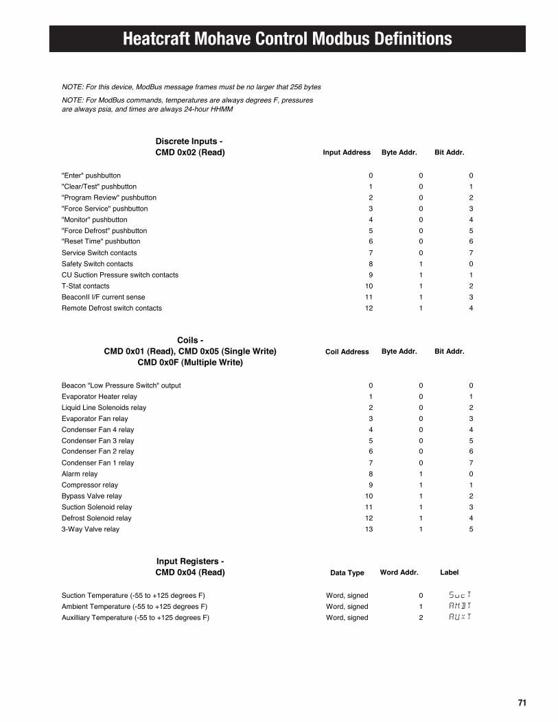
71
Heatcraft Mohave Control Modbus DefinitionsHeatcraft Mohave Control Rev. 17 10/4/2016ModBus Definitions
NOTE: For this device, ModBus message frames must be no larger that 256 bytes
NOTE: For ModBus commands, temperatures are always degrees F, pressures are always psia, and times are always 24-hour HHMM
Discrete Inputs - CMD 0x02 (Read) Input Address Byte Addr. Bit Addr.
"Enter" pushbutton 0 0 0"Clear/Test" pushbutton 1 0 1"Program Review" pushbutton 2 0 2"Force Service" pushbutton 3 0 3"Monitor" pushbutton 4 0 4"Force Defrost" pushbutton 5 0 5"Reset Time" pushbutton 6 0 6Service Switch contacts 7 0 7Safety Switch contacts 8 1 0CU Suction Pressure switch contacts 9 1 1T-Stat contacts 10 1 2BeaconII I/F current sense 11 1 3Remote Defrost switch contacts 12 1 4
Coils -CMD 0x01 (Read), CMD 0x05 (Single Write) Coil Address Byte Addr. Bit Addr.
CMD 0x0F (Multiple Write)
Beacon "Low Pressure Switch" output 0 0 0Evaporator Heater relay 1 0 1Liquid Line Solenoids relay 2 0 2Evaporator Fan relay 3 0 3Condenser Fan 4 relay 4 0 4Condenser Fan 3 relay 5 0 5Condenser Fan 2 relay 6 0 6Condenser Fan 1 relay 7 0 7Alarm relay 8 1 0Compressor relay 9 1 1Bypass Valve relay 10 1 2Suction Solenoid relay 11 1 3Defrost Solenoid relay 12 1 43-Way Valve relay 13 1 5
Input Registers -CMD 0x04 (Read) Data Type Word Addr. Label
Suction Temperature (-55 to +125 degrees F) Word, signed 0 SucT
Ambient Temperature (-55 to +125 degrees F) Word, signed 1 AMBT
Auxilliary Temperature (-55 to +125 degrees F) Word, signed 2 AUXT

72
Mohave Hot Gas Control Modbus Definitions
Suction Pressure (0 to 300 psia), displayed as 30" Hg to 285 psig Word 3 SucP
Liquid Pressure (0 to 500 psia), displayed as 30" Hg to 485 psig Word 4 LIQP
Evap 1 Defrost Temp (-55 to +125 degrees F) Word, signed 5 E1DT
Evap 2 Defrost Temp (-55 to +125 degrees F) Word, signed 6 E2DT
Saturated Suction Temp (-55 to +125 degrees F) Word, signed 7 SSuc
Suction Superheat (-128 to +127 degrees F) Word, signed 8 SUPH
Regulator Valve position (0 to 820 steps) Word 9 VALP
AC input voltage (0 to 315 volts*10), e.g. 243 = 24.3 Vac Word 10 ACIN
SELECT control position (0=full CCW to 255=full CW) Word 11Errors (bit-packed): Word 12 0x0001 CU Suction Temperature sensor error Err1
0x0002 CU Ambient Temperature sensor error Err2
0x0004 CU Aux Temperature sensor error Err3
0x0008 CU Suction Pressure sensor error Err4
0x0010 CU Liquid Pressure sensor error Err5
0x0020 Evaporator #1 Defrost Temperature sensor error Err6
0x0040 Evaporator #2 Defrost Temperature sensor error Err7
0x0080 CU Suction Pressure switch error Err8
0x0100 Safety Circuit shut-down error Err9
0x0200 Prolonged low suction pressure shut-down error Er10
0x0400 Low-pressure start-up error Er11
0x0800 High-pressure start-up error Er12
0x1000 Defrost pump-down error Er13
(0x2000 to 0x8000 not used)Alarms (bit-packed): Word 13 0x0001 Persistent input sensor failure alarm Alr1
0x0002 CU Suction Pressure sensor & switch failure alarm Alr2
0x0004 repeated safety circuit open condition alarm Alr3
0x0008 Persistent low- or high-pressure startup failure alarm Alr4
0x0010 High CU Aux (Room) Temperature alarm Alr5
0x0020 Low CU Aux (Room) Temperature alarm Alr6
(0x0040 to 0x8000 not used)Software Version (RRrr - MAJOR.minor revision); e.g. 107 = 1.07 Word 14 VERS
Operating Mode (0=Off, 1=Delay, 2=Cooling, 3=Pump-Down, 4=Defrost1, 5=Defrost2, 6=Defrost3, 7=DefrostA, 8=Re-Freeze, 9=Test, 10=Service) Word 15
OFF DELY
COOL PUMP
DEF1 DEF2
DEF3 DEFA
FREZ TEST
SERV
Status/Configuration (bit-packed): Word 16 0x0001 Displayed temperature units (0=degrees F, 1=degrees C) 0x0002 Displayed time mode (0=12 hour, 1=24 hour) 0x0004 Application Type (0=Low temp, 1=Medium temp) 0x0008 Evaporator fan mode if not cooling (0=off, 1=on) 0x0010 Expert mode (0=off, 1=on) XPRT
0x0020 Parameter lock mode (0=unlocked, 1=locked) 0x0040 Service mode configured (0=off, 1=on) 0x0080 CU Aux Room Temperature control (0=off, 1=on) 0x0100 CU Aux Temperature sensor attached (0=no, 1=yes) 0x0200 Evaporator #2 temperature sensor attached (0=no, 1=yes) 0x1000 Remote control (0=off, 1=on) 0x2000 Error status (0=no errors, 1=one or more errors detected) 0x4000 Alarm status (0=no alarms, 1=one or more alarms detected) (0x0400, 0x0800, 0x8000 not used)

73
Last elapsed defrost time (minutes) Word 17 DFTM
Compressor cycles since midnight (0 to 255) Word 18 CCYC
Run time since midnight (0000 to 2359 HHMM) Word 19 RnTM
Elapsed time since last defrost (00000 to 25559 HHHMM) Word 20 ETLD
Run time since last defrost (00000 to 25559 HHHMM) Word 21 RTLD
Holding Registers - CMD 0x03 (Read), CMD 0x06 (Single Write) Data Type Word Addr. Label
CMD 0x10 (Multiple Write)
Display Right char. (7-bit ASCII + 0x80 DP) Word 0Display Ctr-Right char. (7-bit ASCII + 0x80 DP) Word 1Display Ctr-Left char. (7-bit ASCII + 0x80 DP) Word 2Display Left char. (7-bit ASCII + 0x80 DP) Word 3Time of Day (0000 to 2359 HHMM) Word 4 CLKH CLKM
Pressure Regulator setpoint (0 to 820 steps) Word 5
revised Refrigerant Type (0=R-22, 1=R-404A, 2=R-507, 3=R-407A, 4=R-407C, 5=R-407F, 6=R-448A, 7=R-449A) Word 6
REFR
Application Type (0=Low temp, 1=Medium temp) Word 7 APPL
Model Number (500 to 5000) Word 8 MODL
Displayed temperature units (0=degrees F, 1=degrees C) Word 9 øFøC
Displayed time mode (0=12 hour, 1=24 hour) Word 10 1224
Evaporator fan mode if not cooling (0=off, 1=on) Word 11 EVPF
Parameter lock mode (0=unlocked, 1=locked) Word 12Number of evaporators (1 or 2) Word 13Evaporator #1 defrost termination temp (+50 to +100 degrees F) Word, signed 14 DFT1
Evaporator #2 defrost termination temp (+50 to +100 degrees F) Word, signed 15 DFT2
Defrost termination pressure (175 to 315 psia), displayed as 160 to 300 psig Word 16 DEFP
Defrost override time limit (5 to 30 minutes) Word 17 DEFT
Alarm condition duration (2 to 120 minutes) Word 18 ALRT
Pressure Regulator full scale (100 to 820 steps) Word 19 PRFS
Equalization time (1 to 10 minutes) Word 20 EQUT
Low Pressure Switch high limit (15 to 45 psia), displayed as 0 to 30 psig Word 21 LPSH
Low Pressure Switch low limit (15 to 45 psia), displayed as 0 to 30 psig Word 22 LPSL
Evaporator re-freeze temperature threshold (+20 to +40 degrees F) Word, signed 23 FZET
Normal valve update interval (10 to 30 seconds) Word 24 PRUI
Initial defrost Pressure Regulator opening (50 to 100%) Word 25 DFIO
Evaporator re-freeze time limit (0 to 10 minutes) Word 26 FZTM
Cooling mode LLS Pulsing time limit (0 to 15 minutes) Word 27 LLSP
ESV/PR valve manufacturer (0=Carel or 1=Alco) Word 28 VALM
CU Aux Room Temperature control (0=off, 1=on) Word 29 AUXT
CU Aux Room Temperature setpoint (-25 to +50 degrees F) Word, signed 30 BOXT
High CU Aux Temp Alarm threshold (-35 to +100 degrees F), +127 if disabled Word, signed 31 ALRH
Low CU Aux Temp Alarm threshold (-35 to +100 degrees F), -128 if disabled Word, signed 32 ALRL
Run-time defrost interval (0030 to 1200 HHMM), 0000 if disabled Word 33 RTDF
Defrost #1 start time (0000 to 2330 HHMM), 2530 if not used Word 34 DF01
Defrost #2 start time (0000 to 2330 HHMM), 2530 if not used Word 35 DF02
Defrost #3 start time (0000 to 2330 HHMM), 2530 if not used Word 36 DF03
Defrost #4 start time (0000 to 2330 HHMM), 2530 if not used Word 37 DF04
Defrost #5 start time (0000 to 2330 HHMM), 2530 if not used Word 38 DF05
Defrost #6 start time (0000 to 2330 HHMM), 2530 if not used Word 39 DF06
Defrost #7 start time (0000 to 2330 HHMM), 2530 if not used Word 40 DF07
Heatcraft Mohave Control Modbus Definitions

74
Defrost #8 start time (0000 to 2330 HHMM), 2530 if not used Word 41 DF08
Defrost #9 start time (0000 to 2330 HHMM), 2530 if not used Word 42 DF09
Defrost #10 start time (0000 to 2330 HHMM), 2530 if not used Word 43 DF10
Defrost #11 start time (0000 to 2330 HHMM), 2530 if not used Word 44 DF11
Defrost #12 start time (0000 to 2330 HHMM), 2530 if not used Word 45 DF12
Number of CU fans (1 to 4) Word 46CU Fan #1 mode (0=off, 1=on, 2=press. ctl., 3=temp. ctl.) Word 47 FAN1
CU Fan #2 mode (0=off, 1=on, 2=press. ctl., 3=temp. ctl.) Word 48 FAN2
CU Fan #3 mode (0=off, 1=on, 2=press. ctl., 3=temp. ctl.) Word 49 FAN3
CU Fan #4 mode (0=off, 1=on, 2=press. ctl., 3=temp. ctl.) Word 50 FAN4
CU Fan #1 On pressure (125 to 315 psia), displayed as 110 to 300 psig Word 51 F1ON
CU Fan #2 On pressure (125 to 315 psia), displayed as 110 to 300 psig Word 52 F2ON
CU Fan #3 On pressure (125 to 315 psia), displayed as 110 to 300 psig Word 53 F3ON
CU Fan #4 On pressure (125 to 315 psia), displayed as 110 to 300 psig Word 54 F4ON
CU Fan #1 Off pressure (125 to 315 psia), displayed as 110 to 300 psig Word 55 F1OF
CU Fan #2 Off pressure (125 to 315 psia), displayed as 110 to 300 psig Word 56 F2OF
CU Fan #3 Off pressure (125 to 315 psia), displayed as 110 to 300 psig Word 57 F3OF
CU Fan #4 Off pressure (125 to 315 psia), displayed as 110 to 300 psig Word 58 F4OF
CU Fan #1 On temperature (+30 to +90 degrees F) Word, signed 59 F1ON
CU Fan #2 On temperature (+30 to +90 degrees F) Word, signed 60 F2ON
CU Fan #3 On temperature (+30 to +90 degrees F) Word, signed 61 F3ON
CU Fan #4 On temperature (+30 to +90 degrees F) Word, signed 62 F4ON
CU Fan #1 Off temperature (+30 to +90 degrees F) Word, signed 63 F1OF
CU Fan #2 Off temperature (+30 to +90 degrees F) Word, signed 64 F2OF
CU Fan #3 Off temperature (+30 to +90 degrees F) Word, signed 65 F3OF
CU Fan #4 Off temperature (+30 to +90 degrees F) Word, signed 66 F4OF
(not used) --- 67 to 7999Remote Control (0xAA55=activate, 0xFF00=deactivate) Word 8000
NOTE: The Write Remote Control command with a data value of 'activate' is ignored unless the Mohave Control is in "Off" or "Service" modes
Diagnostic -CMD 0x08 (Read/Write) Sub-Function
Restart communications 0x01Clear Counters and Diagnostic Register 0x0ARead Bus Message Counter 0x0BRead Bus Communication Error Counter 0x0CRead Bus Exception Error Counter 0x0DRead Slave Message Counter 0x0ERead Slave No Response Counter 0x0FRead Slave NAK Counter 0x10Read Slave Busy Counter 0x11Read Bus Character Overrun Counter 0x12Clear Overrun Counter and Flag 0x14Activate Remote Control mode 0xAA55Deactivate Remote Control mode 0xFF00
NOTE: The Activate Remote Control command is ignored unless the Mohave Control is in "Off" or "Service" modes
Mohave Hot Gas Control Modbus Definitions

75
Notes

Heatcraft Refrigeration Products LLC
2175 West Park Place Blvd. • Stone Mountain, GA 30087770-465-5600 • Fax: 770-465-5990 • www.heatcraftrpd.com
Since product improvement is a continuing effort,we reserve the right to make changes in specifications without notice.
H-IM-HGD0617 | Version 001