MODULIFT NEW PRODUCT LAUNCH! The CMOD Modular Spreader … · Modulift, the market leaders in...
5
12 37 11 46 36 10 57 44 34 9 57 55 42 33 8 57 57 44 38 32 7 57 57 44 38 35 30 6 57 57 44 38 35 34 29 5 57 57 44 38 35 34 32 28 4 57 57 44 38 35 34 32 31 28 3 57 57 44 38 35 34 32 31 31 27 2 57 57 44 38 35 34 32 31 31 31 27 1 57 57 44 38 35 34 32 31 31 31 30 26 1 2 3 4 5 6 7 8 9 10 11 12 8 23 7 32 22 6 34 30 21 5 34 34 25 19 4 34 34 25 21 18 3 34 34 25 21 20 17 2 34 34 25 21 20 19 17 1 34 34 25 21 20 19 18 16 1 2 3 4 5 6 7 8 8 13 7 18 12 6 25 17 12 5 27 23 16 11 4 27 27 20 15 10 3 27 27 20 17 14 10 2 27 27 20 17 16 13 9 1 27 27 20 17 16 15 13 9 1 2 3 4 5 6 7 8 11 32 10 44 31 9 50 42 29 8 50 48 35 28 7 50 48 35 31 27 6 50 48 35 31 28 26 5 50 48 35 31 28 27 25 4 50 48 35 31 28 27 26 24 3 50 48 35 31 28 27 26 26 23 2 50 48 35 31 28 27 26 26 25 23 1 50 48 35 31 28 27 26 26 25 25 23 1 2 3 4 5 6 7 8 9 10 11 11 18 10 25 18 9 32 24 17 8 40 30 23 16 7 40 39 28 22 15 6 40 39 28 25 21 15 5 40 39 28 25 22 20 14 4 40 39 28 25 22 22 19 14 3 40 39 28 25 22 22 21 18 13 2 40 39 28 25 22 22 21 21 18 13 1 40 39 28 25 22 22 21 21 20 18 13 1 2 3 4 5 6 7 8 9 10 11 12 65 11 70 62 10 70 70 54 9 70 70 54 47 8 70 70 54 47 44 7 70 70 54 47 44 42 6 70 70 54 47 44 42 40 5 70 70 54 47 44 42 40 39 4 70 70 54 47 44 42 40 39 38 3 70 70 54 47 44 42 40 39 38 38 2 70 70 54 47 44 42 40 39 38 38 37 1 70 70 54 47 44 42 40 39 38 38 37 36 1 2 3 4 5 6 7 8 9 10 11 12 +44 (0) 1202 621511 www.modulift.com CMOD 34 SWL - 60° ISA/ 60° BSA / 30° STV CMOD 34 SWL - 90° ISA / 45° STV / 45° BSA CMOD 50 SWL - 60° ISA/ 60° BSA / 30° STV CMOD 50 SWL - 90° ISA / 45° STV / 45° BSA CMOD 70 SWL - 60° ISA/ 60° BSA / 30° STV CMOD 70 SWL - 90° ISA / 45° STV / 45° BSA (X & Y Axis span in metres, SWL in tonnes) Load Charts CMOD 34 to CMOD 70 The CMOD Modular Spreader Frame Modulift, the market leaders in Spreader Beam design and manufacture, have extended their modular offering, by launching the CMOD Modular Spreader Frame! A truly adaptable frame that maintains its engineering principles as its configuration adapts. Designed with ease and economy in mind - the CMOD is simple to set up, manoeuvre, and reconfigure to any size frame - allowing for multiple uses and diverse application. The CMOD is a modular frame utilising Corner Units which are compatible with our existing Spreader Beam Struts and is modular in length and width. Every CMOD Spreader Frame consists of 4 x Corner Units, with intermediate Struts that can be bolted into the assembly to achieve different spans. Existing customers can adapt their Spreader Beam into a frame, by simply bolting on the corresponding Corner Units and any additional Struts required. Even the largest CMOD can be easily transported as the frame is broken down into modular parts, saving the cost of specialist transportation. Corner Unit Strut Fig. 1: Example CMOD Modular Spreader Frame MODULIFT NEW PRODUCT LAUNCH! +44 (0) 1202 621511 www.modulift.com
Transcript of MODULIFT NEW PRODUCT LAUNCH! The CMOD Modular Spreader … · Modulift, the market leaders in...
12 37
11 46 36
10 57 44 34
9 57 55 42 33
8 57 57 44 38 32
7 57 57 44 38 35 30
6 57 57 44 38 35 34 29
5 57 57 44 38 35 34 32 28
4 57 57 44 38 35 34 32 31 28
3 57 57 44 38 35 34 32 31 31 27
2 57 57 44 38 35 34 32 31 31 31 27
1 57 57 44 38 35 34 32 31 31 31 30 26
1 2 3 4 5 6 7 8 9 10 11 12
8 23
7 32 22
6 34 30 21
5 34 34 25 19
4 34 34 25 21 18
3 34 34 25 21 20 17
2 34 34 25 21 20 19 17
1 34 34 25 21 20 19 18 16
1 2 3 4 5 6 7 8
8 13
7 18 12
6 25 17 12
5 27 23 16 11
4 27 27 20 15 10
3 27 27 20 17 14 10
2 27 27 20 17 16 13 9
1 27 27 20 17 16 15 13 9
1 2 3 4 5 6 7 8
11 32
10 44 31
9 50 42 29
8 50 48 35 28
7 50 48 35 31 27
6 50 48 35 31 28 26
5 50 48 35 31 28 27 25
4 50 48 35 31 28 27 26 24
3 50 48 35 31 28 27 26 26 23
2 50 48 35 31 28 27 26 26 25 23
1 50 48 35 31 28 27 26 26 25 25 23
1 2 3 4 5 6 7 8 9 10 11
11 18
10 25 18
9 32 24 17
8 40 30 23 16
7 40 39 28 22 15
6 40 39 28 25 21 15
5 40 39 28 25 22 20 14
4 40 39 28 25 22 22 19 14
3 40 39 28 25 22 22 21 18 13
2 40 39 28 25 22 22 21 21 18 13
1 40 39 28 25 22 22 21 21 20 18 13
1 2 3 4 5 6 7 8 9 10 11
12 65
11 70 62
10 70 70 54
9 70 70 54 47
8 70 70 54 47 44
7 70 70 54 47 44 42
6 70 70 54 47 44 42 40
5 70 70 54 47 44 42 40 39
4 70 70 54 47 44 42 40 39 38
3 70 70 54 47 44 42 40 39 38 38
2 70 70 54 47 44 42 40 39 38 38 37
1 70 70 54 47 44 42 40 39 38 38 37 36
1 2 3 4 5 6 7 8 9 10 11 12
+44 (0) 1202 621511 www.modulift.com
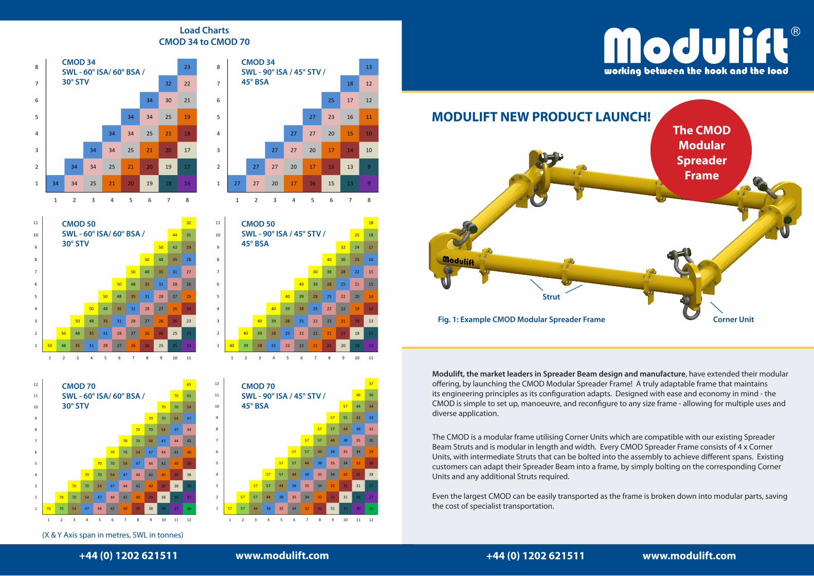
CMOD 34 SWL - 60° ISA/ 60° BSA / 30° STV
CMOD 34 SWL - 90° ISA / 45° STV / 45° BSA
CMOD 50 SWL - 60° ISA/ 60° BSA / 30° STV
CMOD 50 SWL - 90° ISA / 45° STV / 45° BSA
CMOD 70 SWL - 60° ISA/ 60° BSA / 30° STV
CMOD 70 SWL - 90° ISA / 45° STV / 45° BSA
(X & Y Axis span in metres, SWL in tonnes)
Load ChartsCMOD 34 to CMOD 70
The CMOD
Modular Spreader
Frame
Modulift, the market leaders in Spreader Beam design and manufacture, have extended their modular offering, by launching the CMOD Modular Spreader Frame! A truly adaptable frame that maintains its engineering principles as its configuration adapts. Designed with ease and economy in mind - the CMOD is simple to set up, manoeuvre, and reconfigure to any size frame - allowing for multiple uses and diverse application.
The CMOD is a modular frame utilising Corner Units which are compatible with our existing Spreader Beam Struts and is modular in length and width. Every CMOD Spreader Frame consists of 4 x Corner Units, with intermediate Struts that can be bolted into the assembly to achieve different spans. Existing customers can adapt their Spreader Beam into a frame, by simply bolting on the corresponding Corner Units and any additional Struts required.
Even the largest CMOD can be easily transported as the frame is broken down into modular parts, saving the cost of specialist transportation.
Corner Unit
Strut
Fig. 1: Example CMOD Modular Spreader Frame
MODULIFT NEW PRODUCT LAUNCH!
+44 (0) 1202 621511 www.modulift.com
Tel: +44 (0) 1202 621511 Fax: +44 (0) 1202 632811
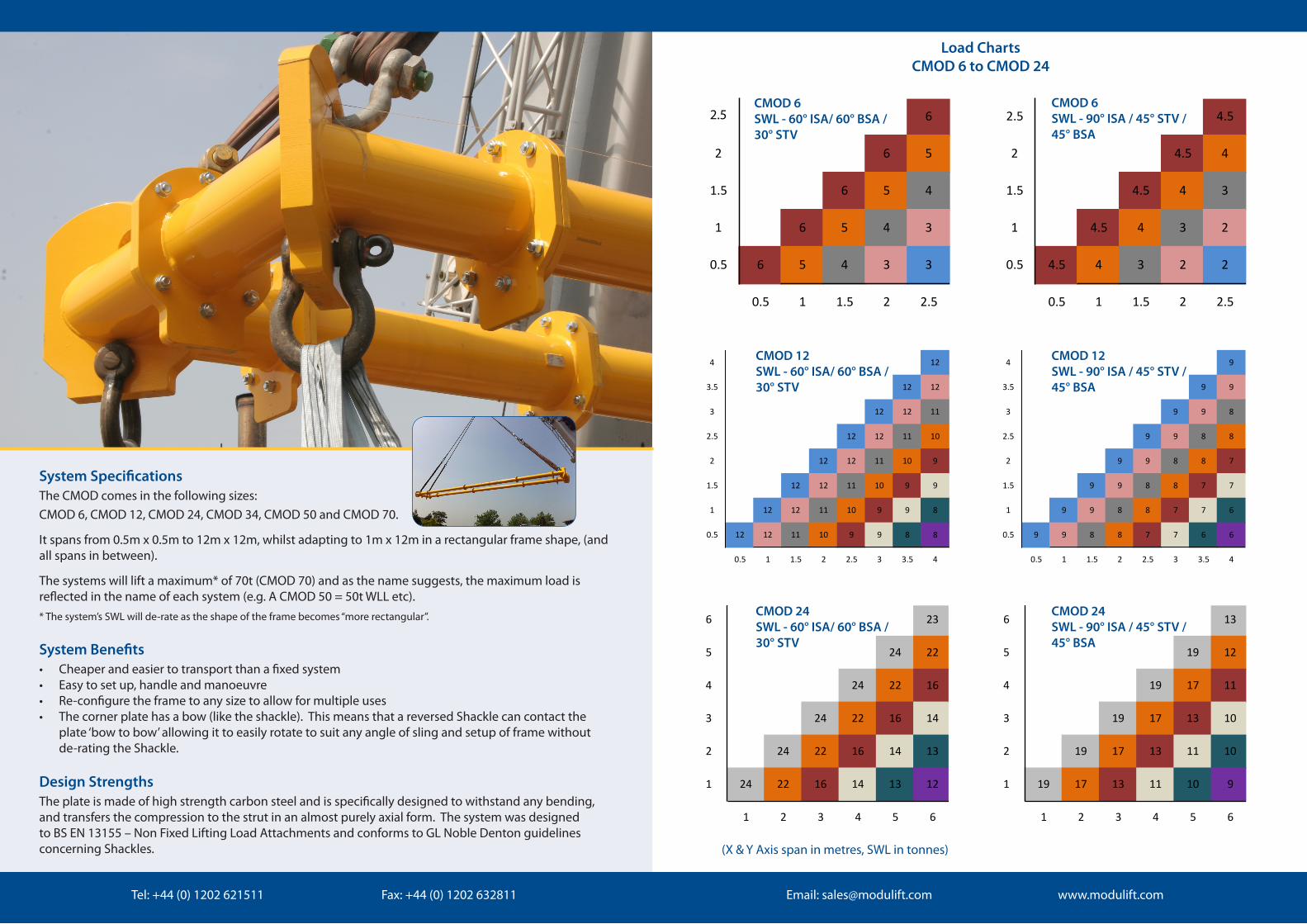
System SpecificationsThe CMOD comes in the following sizes: CMOD 6, CMOD 12, CMOD 24, CMOD 34, CMOD 50 and CMOD 70.
It spans from 0.5m x 0.5m to 12m x 12m, whilst adapting to 1m x 12m in a rectangular frame shape, (and all spans in between).
The systems will lift a maximum* of 70t (CMOD 70) and as the name suggests, the maximum load is reflected in the name of each system (e.g. A CMOD 50 = 50t WLL etc). * The system’s SWL will de-rate as the shape of the frame becomes “more rectangular”.
System Benefits• Cheaper and easier to transport than a fixed system• Easy to set up, handle and manoeuvre• Re-configure the frame to any size to allow for multiple uses • The corner plate has a bow (like the shackle). This means that a reversed Shackle can contact the
plate ‘bow to bow’ allowing it to easily rotate to suit any angle of sling and setup of frame without de-rating the Shackle.
Design StrengthsThe plate is made of high strength carbon steel and is specifically designed to withstand any bending, and transfers the compression to the strut in an almost purely axial form. The system was designed to BS EN 13155 – Non Fixed Lifting Load Attachments and conforms to GL Noble Denton guidelines concerning Shackles.
Email: [email protected] www.modulift.com
2.5 6
2 6 5
1.5 6 5 4
1 6 5 4 3
0.5 6 5 4 3 3
0.5 1 1.5 2 2.5
2.5 4.5
2 4.5 4
1.5 4.5 4 3
1 4.5 4 3 2
0.5 4.5 4 3 2 2
0.5 1 1.5 2 2.5
4 12
3.5 12 12
3 12 12 11
2.5 12 12 11 10
2 12 12 11 10 9
1.5 12 12 11 10 9 9
1 12 12 11 10 9 9 8
0.5 12 12 11 10 9 9 8 8
0.5 1 1.5 2 2.5 3 3.5 4
4 9
3.5 9 9
3 9 9 8
2.5 9 9 8 8
2 9 9 8 8 7
1.5 9 9 8 8 7 7
1 9 9 8 8 7 7 6
0.5 9 9 8 8 7 7 6 6
0.5 1 1.5 2 2.5 3 3.5 4
6 23
5 24 22
4 24 22 16
3 24 22 16 14
2 24 22 16 14 13
1 24 22 16 14 13 12
1 2 3 4 5 6
6 13
5 19 12
4 19 17 11
3 19 17 13 10
2 19 17 13 11 10
1 19 17 13 11 10 9
1 2 3 4 5 6
CMOD 6 SWL - 60° ISA/ 60° BSA / 30° STV
CMOD 6 SWL - 90° ISA / 45° STV / 45° BSA
CMOD 12 SWL - 60° ISA/ 60° BSA / 30° STV
CMOD 12 SWL - 90° ISA / 45° STV / 45° BSA
CMOD 24 SWL - 60° ISA/ 60° BSA / 30° STV
CMOD 24 SWL - 90° ISA / 45° STV / 45° BSA
(X & Y Axis span in metres, SWL in tonnes)
Load ChartsCMOD 6 to CMOD 24
Email: [email protected] www.modulift.com
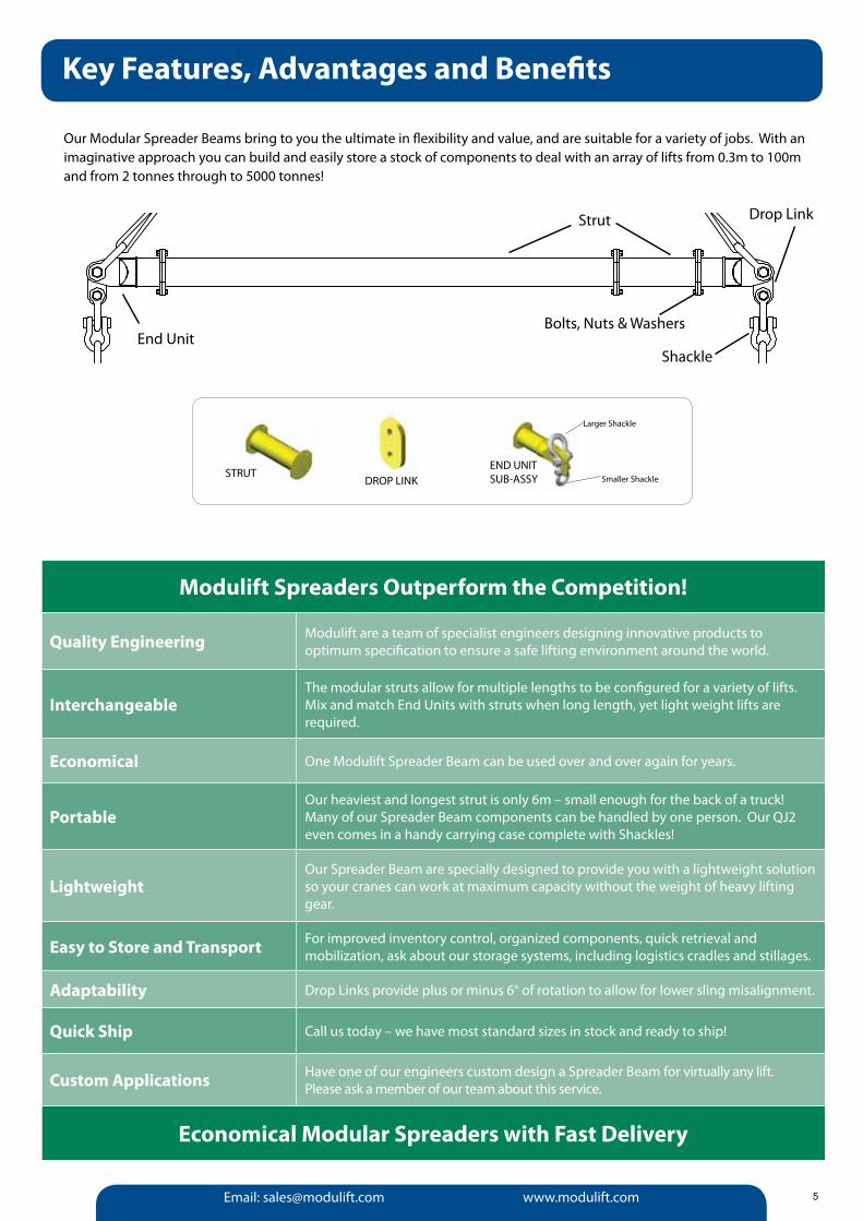
Our Modular Spreader Beams bring to you the ultimate in flexibility and value, and are suitable for a variety of jobs. With an imaginative approach you can build and easily store a stock of components to deal with an array of lifts from 0.3m to 100m and from 2 tonnes through to 5000 tonnes!
Modulift Spreaders Outperform the Competition!
Quality Engineering Modulift are a team of specialist engineers designing innovative products to optimum specification to ensure a safe lifting environment around the world.
InterchangeableThe modular struts allow for multiple lengths to be configured for a variety of lifts. Mix and match End Units with struts when long length, yet light weight lifts are required.
Economical One Modulift Spreader Beam can be used over and over again for years.
PortableOur heaviest and longest strut is only 6m – small enough for the back of a truck! Many of our Spreader Beam components can be handled by one person. Our QJ2 even comes in a handy carrying case complete with Shackles!
LightweightOur Spreader Beam are specially designed to provide you with a lightweight solution so your cranes can work at maximum capacity without the weight of heavy lifting gear.
Easy to Store and Transport For improved inventory control, organized components, quick retrieval and mobilization, ask about our storage systems, including logistics cradles and stillages.
Adaptability Drop Links provide plus or minus 6° of rotation to allow for lower sling misalignment.
Quick Ship Call us today – we have most standard sizes in stock and ready to ship!
Custom Applications Have one of our engineers custom design a Spreader Beam for virtually any lift. Please ask a member of our team about this service.
Economical Modular Spreaders with Fast Delivery
Key Features, Advantages and Benefits
End Unit
Strut
Bolts, Nuts & Washers
Drop Link
Shackle
STRUTDROP LINK
END UNIT SUB-ASSY
Larger Shackle
Smaller Shackle
5

Tel: +44 (0) 1202 621511 Fax: +44 (0) 1202 632811
What Size Shackle Do I Need?MOD 6
MOD 12
TOP: 4.75tLOWER: 3.25t
MOD 110 / 110H
MOD 70 / 70H
MOD 50
MOD 34
MOD 24
TOP: 8.5tLOWER: 6.5t
TOP: 17tLOWER: 12t
TOP: 25tLOWER: 17t
TOP: 55t / 85tLOWER: 35t / 55t
TOP: 35tLOWER: 25t
TOP: 85Tt/ 120tLOWER: 55t / 85t
The Standard Range
6
128127126125124123122121120119118117116115114113112111110109108107106105104103102101100999897969594939291908988878685848382818079787776757473727170696867666564636261605958575655545352515049484746454443424140393837363534333231302928272625242322212019181716151413121110987654321
1 4 5 6 7 8 9 10 11 12 13 14 15 162 3
Span / Metres
*50t End Units are available for the Mod 70H**85t End Units are available for the Mod 110H
MOD 6
MOD 12
MOD 24
MOD 34
MOD 50
MOD 70
MOD 70H*
MOD 110
MOD 110H**
Components per SetMaintenance
Range Portable Range Heavy Range Super Heavy Range
ITEM MOD 6 MOD 12 MOD 24 MOD 34 MOD 50 MOD 70(H) MOD 110(H) MOD 110SH MOD 250 MOD 400
0.1m 1 - - - - - - - - -
0.2m 1 - - - - - - - - -
0.25m - 1 - - - - - - - -
0.3m 1 - - - - - - - - -
0.5m - 1 1 1 1 1 - 1 1 -
0.6m 1 - - - - - - - - -
0.75m - 1 - - - - - - - -
1m 1 1 1 1 1 1 1 1 1 1
1.5m - 1 - - - - - - - -
2m - - 2 3 1 1 1 1 1 1
3m - - - - - - - - 1 1
4m - - - - 2 2 3 3 - -
6m - - - - - - - - 2 3
End Unit 2 2 2 2 2 2 2 2 2 2
Drop Link 2 2 2 2 2 2 2 2 2 2
Load v Span for MOD 6 to MOD 110H @ 90° θ (Included Sling Angle) ISA
Safe
Wor
king
Loa
d / t
onne
s @
90°
θ S
ling
Ang
le
Email: [email protected] www.modulift.com
What Size Shackle Do I Need?
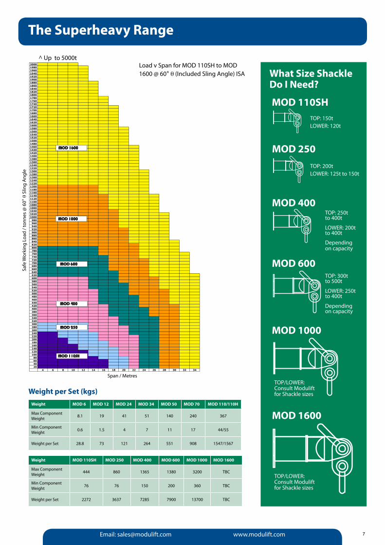
MOD 110SH
MOD 1600
MOD 1000
MOD 600
MOD 400
MOD 250
TOP: 150tLOWER: 120t
TOP: 200tLOWER: 125t to 150t
TOP: 250t to 400t
LOWER: 200t to 400t
Depending on capacity
TOP: 300t to 500t
LOWER: 250t to 400t
Depending on capacity
TOP/LOWER:Consult Modulift for Shackle sizes
TOP/LOWER:Consult Modulift for Shackle sizes
The Superheavy Range
7
20001980196019401920190018801860184018201800178017601740172017001680166016401620160015801560154015201500148014601440142014001380136013401320130012801260124012201200118011601140112011001080106010401020100098096094092090088086084082080078076074072070068066064062060058056054052050048046044042040038036034032030028026024022020018016014012010080604020
4 6 8 10 12 14 16 18 20 22 24 26 28 30 32 34
Span / Metres
MOD 1600
MOD 1000
MOD 600
MOD 400
MOD 250
MOD 110SH
Weight per Set (kgs)Weight MOD 6 MOD 12 MOD 24 MOD 34 MOD 50 MOD 70 MOD 110/110H
Max Component Weight 8.1 19 41 51 140 240 367
Min Component Weight 0.6 1.5 4 7 11 17 44/55
Weight per Set 28.8 73 121 264 551 908 1547/1567
Weight MOD 110SH MOD 250 MOD 400 MOD 600 MOD 1000 MOD 1600
Max Component Weight 444 860 1365 1380 3200 TBC
Min Component Weight 76 76 150 200 360 TBC
Weight per Set 2272 3637 7285 7900 13700 TBC
^ Up to 5000tLoad v Span for MOD 110SH to MOD 1600 @ 60° θ (Included Sling Angle) ISA
Safe
Wor
king
Loa
d / t
onne
s @
60°
θ S
ling
Ang
le