Module I: Electromagnetic waves -...
29
Module I: Electromagnetic waves Lectures 6-7: EM waves in confined spaces Amol Dighe TIFR, Mumbai
Transcript of Module I: Electromagnetic waves -...

Module I: Electromagnetic wavesLectures 6-7: EM waves in confined spaces
Amol DigheTIFR, Mumbai
Outline
1 Waveguides
2 Rectangular waveguide
3 Phase and group velocities
4 Circular cylindrical waveguides
5 Coaxial cable
6 Cavities

Coming up...
1 Waveguides
2 Rectangular waveguide
3 Phase and group velocities
4 Circular cylindrical waveguides
5 Coaxial cable
6 Cavities

Travelling waves with the same (x , y) profile
We are looking for waves travelling in z direction, while keepingthe same (x , y) profile. I.e. the form
~E = ~E0(x , y)ei(kz z−ωt) , ~B = ~B0(x , y)ei(kz z−ωt) (1)
Maxwell’s (∇× ~E) and (∇× ~B) equations then become
∂Ey
∂x− ∂Ex
∂y= iωBz ,
∂By
∂x− ∂Bx
∂y= − iω
c2 Ez (2)
∂Ez
∂y− ikzEy = iωBx ,
∂Bz
∂y−−ikzBy = − iω
c2 Ex (3)
ikzEx −∂Ez
∂x= iωBy , ikzBx −
∂Bz
∂x= − iω
c2 Ey (4)
Note that one can factor out the ei(kz z−ωt) dependence ofEx ,Ey ,Ez and Bx ,By ,Bz , so now onwards they have no z- ort-dependence in this lecture.
Using the last two lines (4 equations), one can writeEx ,Ey ,Bx ,By in terms of the other two quantities, Ez and Bz

All components in terms of Ez and Bz
Ex =1
(ω/c)2 − k2z
(kz∂Ez
∂x+ ω
∂Bz
∂y
)(5)
Ey =1
(ω/c)2 − k2z
(kz∂Ez
∂y− ω∂Bz
∂x
)(6)
Bx =i
(ω/c)2 − k2z
(kz∂Bz
∂x− ω
c2∂Ez
∂y
)(7)
By =i
(ω/c)2 − k2z
(kz∂Bz
∂y+ω
c2∂Ez
∂x
)(8)
Note that if Ez and Bz both vanish (or are constants), no othercomponents of ~E or ~B can survive (unless kz = 0, which caseneeds to be treated separately.)
However Ez and Bz are not free parameters; the aboveequations just give four constraints on ~E and ~B, two moreconstraints from the last page are still remaining.

Constraining Ez ,Bz themselves
Ez ,Bz themselves must satisfy consistency conditions
∂Ey
∂x− ∂Ex
∂y= iωBz (9)
∂By
∂x− ∂Bx
∂y= − iω
c2 Ez (10)
These correspond to
(∂2
∂x2 +∂2
∂y2 − k2z +
ω2
c2
)Ez = 0 (11)(
∂2
∂x2 +∂2
∂y2 − k2z +
ω2
c2
)Bz = 0 (12)
If there were no boundary conditions in the x − y plane, this wouldhave a plane wave solution – a flat x − y profile . But conductingboundaries imply that these fields must have a non-trivial x −y profile.

EM wave propagation in waveguides
Let us consider rectangular / circular hollow conductingcylinders, through which an EM wave will be “guided” by bendingthe boundaries of the cylinders.
A simple solution would have been a plane wave travelling alongz direction, such that ~E and ~B fields are transverse,Ez = Bz = 0. Such a solution is called as TEM (transverseelectric and magnetic) mode.
Such a mode is not possible in a hollow cylinder, proof given onthe next page
However Ez and Bz can individually vanish, such modes aretermed TE (Transverse electric: Ez = 0) and TM (Transversemagnetic: Bz = 0).

Hollow cylinder cannot have both Ez = 0 and Bz = 0
Since Bz = 0, we have (∇× ~E)z = −∂Bz/∂t = 0. Then
∂Ey
∂x− ∂Ex
∂y= 0 (13)
Since Ex and Ey are independent of z, and Ez = 0, we get∇× ~E = 0, i.e. ~E can be written as ~E = −∇Φ.
In addition, no charges inside the cylinder, so ∇ · E = 0. That is,∇2Φ = 0.
Now we have a boundary value problem, with ∇2Φ = 0 insidethe boundary and Φ =constant on the complete boundary (thehollow conductor).
This boundary value problem has a solution, Φ =constanteverywhere, and the uniqueness theorem states that this is theonly solution.
Thus, there can be no electric / magnetic fields inside thewaveguide.

TE and TM modes
http://www.allaboutcircuits.com/vol_2/chpt_14/8.html

TEM mode
http://www.allaboutcircuits.com/vol_2/chpt_14/8.html

Coming up...
1 Waveguides
2 Rectangular waveguide
3 Phase and group velocities
4 Circular cylindrical waveguides
5 Coaxial cable
6 Cavities
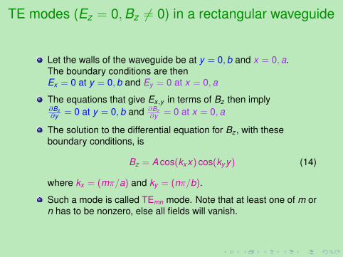
TE modes (Ez = 0,Bz 6= 0) in a rectangular waveguide
Let the walls of the waveguide be at y = 0,b and x = 0,a.The boundary conditions are thenEx = 0 at y = 0,b and Ey = 0 at x = 0,a
The equations that give Ex,y in terms of Bz then imply∂Bz∂y = 0 at y = 0,b and ∂Bz
∂y = 0 at x = 0,a
The solution to the differential equation for Bz , with theseboundary conditions, is
Bz = A cos(kxx) cos(ky y) (14)
where kx = (mπ/a) and ky = (nπ/b).
Such a mode is called TEmn mode. Note that at least one of m orn has to be nonzero, else all fields will vanish.

Cutoff frequencies for TE modes
The TEmn solution, when substituted in the differential equationfor Bz , gives
−(mπ
a
)2−(nπ
b
)2− k2
z + (ω/c)2 = 0 (15)
For consistency with the physical situation, kz must be real; i.e.k2
z > 0. This gives the condition
ω > c
√(mπa
)2+(nπ
b
)2≡ ωmn (16)
Thus, for a TE mode TEmn to propagate, it must have a minimumfrequency ωmn. A waveguide thus acts like a high-pass filter.

TM modes
A similar analysis is possible for TM modes, but this will not bedone here.
Note that the cutoff frequencies ωmn for the TM modes are thesame as those for TE modes.
Coming up...
1 Waveguides
2 Rectangular waveguide
3 Phase and group velocities
4 Circular cylindrical waveguides
5 Coaxial cable
6 Cavities

Phase velocity and group velocity
Phase velocity: simply the speed at which the crest of thewavefront travels in a given direction.
For a plane wave Aei(~k·~x−ωt), the phase velocity along thedirection r̂ is
vph =drdt
∣∣∣∣constant phase
=ω
|~k.̂r|(17)
If ~k is not along r̂, typically vph > c. This does not mean that anysignal is travelling faster than light, though.
Group velocity measures the speed at which a signal istransported. The signal is embedded in the distribution offrequencies, and group velocity measures how fast the peak ofthis distribution shifts. Details on the next page.

Group velocity
The Fourier transform of a wave gives the frequencies the waveconsists of. Consider the situation where the spread infrequencies is small, which is the only one where we can definea group velocity easily. Let the frequencies be confined to therange ω = ω0 ±∆ω. The corresponding wave vectors areconfined to ~k = ~k0 ±∆~k.
The wave isψ(~x, t) =
∫a(~k)ei(~k·~x−ωt)d3k , (18)
which may be written as
ψ(~x, t) = A(~x, t) ei(~k0·~x−ω0t) , (19)
whereA(~x, t) =
∫a(~k)ei(∆~k·~x−∆ωt)d3k (20)
The frequency distribution shifts as a wavepacket, the velocity ofthe peak of the distribution is the approximate velocity of thewavepacket.

Group velocity: continued
Let us consider a one-dimensional case of a wave travellingalong z-axis. At the peak,
0 =dAdt
=∂A∂t
+∂A∂z
dzdt
(21)
The group velocity is then
vg =dzdt
= − ∂A/∂t∂A/∂z
=∆ω
∆k=
dωdk
∣∣∣∣ω0
(22)
Velocities along z axis for the waveguide
ω =√ω2
mn + k2z
Phase velocity vph = ωkz
= c√1−(ωmn/ω)2
Group velocity vg = dωdkz
= c√
1− (ωmn/ω)2
Waveguide transports different frequencies at different speeds:dispersion

Coming up...
1 Waveguides
2 Rectangular waveguide
3 Phase and group velocities
4 Circular cylindrical waveguides
5 Coaxial cable
6 Cavities

Circular cylindrical waveguides
No TEM mode, as per the earlier arguments
For TM modeEz = AJm(k`r)eimφei(kz z−ωt) (23)
If the cylinder has radius r0,then the boundary condition is Jm(k`r0) = 0, gives k`(m)
For TE modeBz = AJm(k`r)eimφei(kz z−ωt) (24)
If the cylinder has radius r0,then the boundary condition is J ′m(k`r0) = 0, gives k`(m)
k2z = (ω/c)2 − k2
` ⇒ cutoff frequency ωm,` = ck`(m)
TM and TE modes have different cutoff frequencies, unlikerectangular waveguides !

Power transmitted by a waveguide
Consider TE mode. i.e. Ez = 0.
The equations for ~E⊥ = (Ex ,Ey ) and ~B⊥ = (Bx ,By ) become
Bx = ikzk2⊥
∂Bz∂x
By = ikzk2⊥
∂Bz∂y
}⇒ ~B⊥ =
ikz
k2⊥∇⊥Bz (25)
Ex = ckk2⊥
∂Bz∂y
Ey = − ckk2⊥
∂Bz∂x
}⇒ ~E⊥ =
ickkz
~B⊥ ×~z (26)
The magnitude of Poynting vector (power transmitted per unitarea) is then
|~N| =|~E∗⊥0 × ~H⊥0|2
2=|~E⊥0|2
2~kzckµ0 =
12
√ε0µ0
kz
k|~E0|2 (27)
Comparing with |~N| = (1/2)σ|E0|2, this enables us to define theconductance of the waveguide as σ =
√ε0/µ0(kz/k). This may
be compared with the conductance of free space,√ε0/µ0.
Coming up...
1 Waveguides
2 Rectangular waveguide
3 Phase and group velocities
4 Circular cylindrical waveguides
5 Coaxial cable
6 Cavities

Coaxial cable
http://en.wikipedia.org/wiki/Coaxial_cable

Propagation through a coaxial cable
TEM Mode is supported (now there are two disjoint boundaries,so the argument for hollow waveguides does not work.)
TE and TM modes also propagate, but have a thresholdfrequency
The TEM mode
Electric and magnetic fields:
~E =E0r̂r
ei(kz z−ωt) , ~B =E0φ̂
crei(kz z−ωt) (28)
Group velocity vg = c
Coming up...
1 Waveguides
2 Rectangular waveguide
3 Phase and group velocities
4 Circular cylindrical waveguides
5 Coaxial cable
6 Cavities

Rectangular cavity
Conducting walls at x = 0,a; at y = 0,b and at z = 0, c.
Potential inside the cavity:
Φmnp = sin(kxx) sin(ky y) sin(kzz)e−iωt (29)
where kx = (mπ/a), ky = (nπ/b), kz = (pπ/c)
This can be used to obtain ~E and ~B inside the cavity.
A rectangular cavity supports discrete modes.

LHC accelerator: cavity principle
http://www.lhc-closer.es/php/index.php?i=1&s=4&p=7&e=2

LHC accelerator: bunching cavities
http://www.lhc-closer.es/php/index.php?i=1&s=4&p=7&e=2
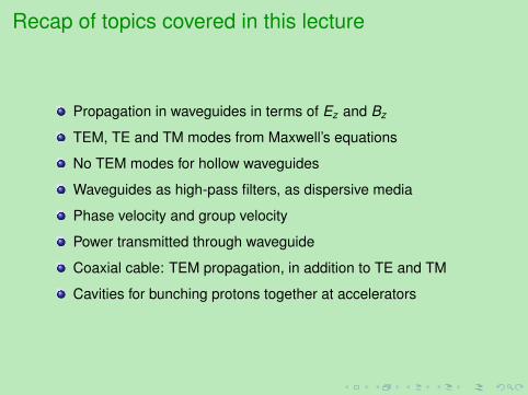
Recap of topics covered in this lecture
Propagation in waveguides in terms of Ez and Bz
TEM, TE and TM modes from Maxwell’s equations
No TEM modes for hollow waveguides
Waveguides as high-pass filters, as dispersive media
Phase velocity and group velocity
Power transmitted through waveguide
Coaxial cable: TEM propagation, in addition to TE and TM
Cavities for bunching protons together at accelerators