Module 8 – (L31 – L34): “Storm Water & Fldlood...
35
Module 8 – (L31 – L34): “Storm l d ” Water & Flood Management”: Storm water management, design of drainage system, flood routing through channels and reservoir flood control and routing through channels and reservoir, flood control and reservoir operation, case studies. 33 Flood Routing 1 1 33 Flood Routing
Transcript of Module 8 – (L31 – L34): “Storm Water & Fldlood...
Module 8 – (L31 – L34): “Storm l d ”Water & Flood Management”:
Storm water management, design of drainage system, flood routing through channels and reservoir flood control and routing through channels and reservoir, flood control and reservoir operation, case studies.
33 Flood Routing11111
33 Flood Routing
L33L33– Flood RoutingL33L33 Flood Routing Topics CoveredTopics Covered Flood routing though channels, Reservoir Flood routing though channels, Reservoir
routing Hydrologic routing Hydraulic routing Hydrologic routing Hydraulic routing, Hydrologic routing, Hydraulic routing, Hydrologic routing, Hydraulic routing, Lumped flow routing, Muskingum routing, Lumped flow routing, Muskingum
h d S V ih d S V imethod, St. Venant equationsmethod, St. Venant equations
Keywords:Keywords: Flood routing, Channel, Reservoir, Flood routing, Channel, Reservoir, yy gg
Hydrologic & hydraulic routing.Hydrologic & hydraulic routing.
2222Prof. T I Eldho, Department of Civil Engineering, IIT Bombay
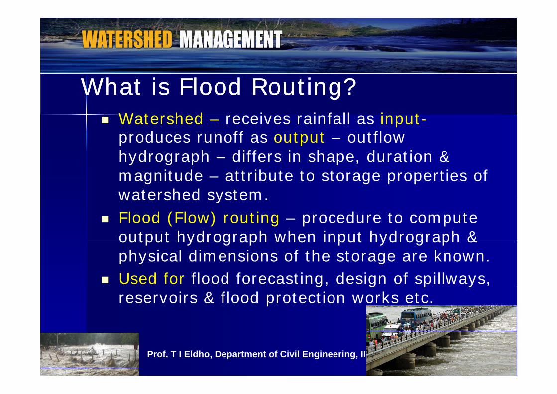
What is Flood Routing?What is Flood Routing? Watershed – receives rainfall as input-
produces runoff as output – outflow h d h diff i h d ti & hydrograph – differs in shape, duration & magnitude – attribute to storage properties of watershed systemwatershed system.
Flood (Flow) routing – procedure to compute output hydrograph when input hydrograph & output hydrograph when input hydrograph & physical dimensions of the storage are known.
Used for flood forecasting, design of spillways, g, g p y ,reservoirs & flood protection works etc.
33Prof. T I Eldho, Department of Civil Engineering, IIT Bombay
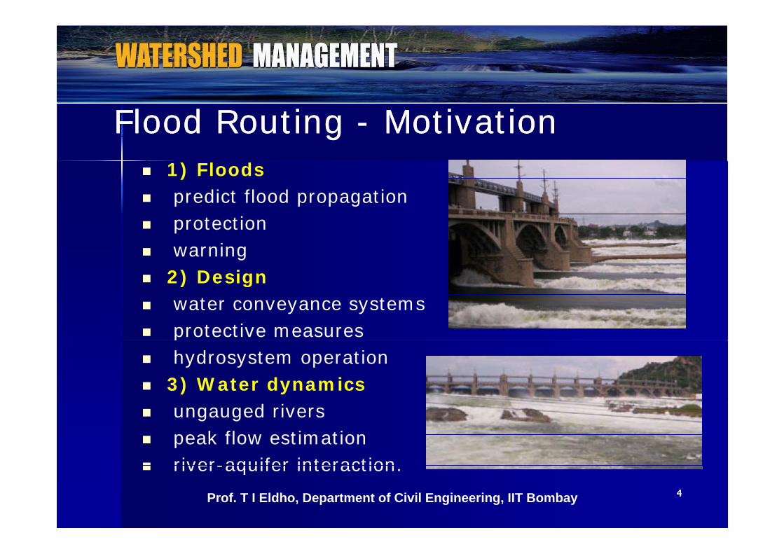
Flood Routing Flood Routing -- MotivationMotivation 1) Floods predict flood propagation protection warning 2) Design 2) Design water conveyance systems protective measuresp hydrosystem operation 3) Water dynamics ungauged rivers peak flow estimation river-aquifer interaction
44
river-aquifer interaction.Prof. T I Eldho, Department of Civil Engineering, IIT Bombay
Flood Routing Flood Routing -- ClassificationClassification i) Reservoir Routing – considers modulation effects on
a flood wave when it passes through a water reservoir –results in outflow hydrographs with attenuated peaks & results in outflow hydrographs with attenuated peaks & enlarged time bases .– Variations in reservoir elevation & outflow can be
predicted with time when relationships between elevation & volume are known.
ii) Channel Routing – considers changes in the shape ii) Channel Routing considers changes in the shape of input hydrograph while flood waves pass through a channel downstream.
Flood hydrographs at various sections predicted when – Flood hydrographs at various sections predicted when input hydrographs & channel characteristics are known.
55Prof. T I Eldho, Department of Civil Engineering, IIT Bombay
Flood Routing Flood Routing –– ProcedureProcedure Flood routing - methods can be classified as hydraulic -
in which both continuity and dynamic equations are used - or hydrologic, which generally uses the continuity or hydrologic, which generally uses the continuity equation alone
d l h d f Hydrologic routing methods - Equation of continuity Hydraulic routing methods – St. Venant equations Flood routing Applications: Flood routing Applications:
-Flood forecasting-Flood protection-Reservoir design-Design of spillway and outlet structures
66Prof. T I Eldho, Department of Civil Engineering, IIT Bombay
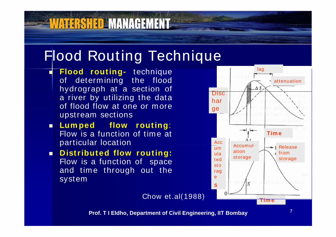
Flood Routing TechniqueFlood Routing Technique Flood routing- technique
of determining the floodhydrograph at a section of Di
lag
attenuation
yd og ap a a sec o oa river by utilizing the dataof flood flow at one or moreupstream sections
Discharge
p Lumped flow routing:
Flow is a function of time atparticular location
TimeAcc
Accumul R l p
Distributed flow routing:Flow is a function of spaceand time through out the
umulated storag
Accumulation storage
Release from storage
and time through out thesystem
Time
rage
S
Chow et.al(1988)
77Prof. T I Eldho, Department of Civil Engineering, IIT Bombay
Time( )
Lumped Flow Routing Basic equation for hydrologic routing: Continuity
equation dSequation ( ) ( )dS I t Q t
dt
Input I(t), Output Q(t) and storage S(t); Known I(t) & unknowns Q & S
Second relation (Storage function) needed to Second relation (Storage function) needed to relate S, I and Q
Specific form of storage function depending on t f tnature of system.
mai
n ch
anne
lm
ain
chan
nel
88Prof. T I Eldho, Department of Civil Engineering, IIT Bombay
Res
ervo
ir in
mR
eser
voir
in m
Lumped Flow Routing - MethodsBased on storage function Level pool reservoir routing - Storage is a
li f ti f Q l S f(Q)nonlinear function of Q only. S = f(Q) Muskingum method for flow routing in
channels Storage is linearly related to I & Qchannels – Storage is linearly related to I & Q Linear reservoir models – Storage is a linear
function of Q and its time derivativesfunction of Q and its time derivatives Effect of reservoir storage is to redistribute the
hydrograph by shifting the centroid of the inflowhydrograph to the position of that of the outflowhydrograph in time
99Prof. T I Eldho, Department of Civil Engineering, IIT Bombay
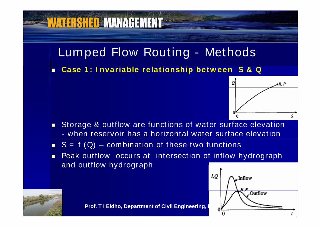
Lumped Flow Routing - Methods Case 1: Invariable relationship between S & Q
Storage & outflow are functions of water surface elevation - when reservoir has a horizontal water surface elevation
S = f (Q) – combination of these two functions Peak outflow occurs at intersection of inflow hydrograph
and outflow hydrographand outflow hydrograph
1010Prof. T I Eldho, Department of Civil Engineering, IIT Bombay
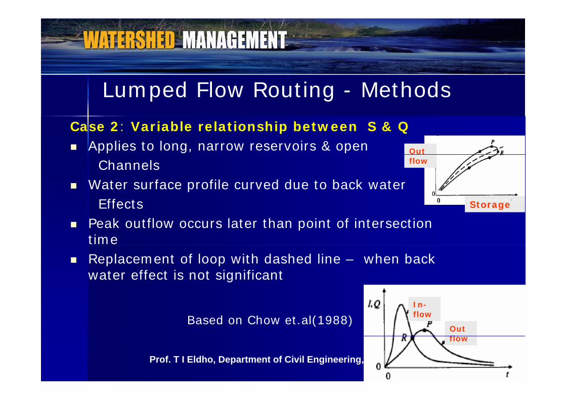
Lumped Flow Routing - MethodsCase 2: Variable relationship between S & Q Applies to long, narrow reservoirs & open Out
Channels Water surface profile curved due to back water
Eff t
flow
Effects Peak outflow occurs later than point of intersection
time
Storage
Replacement of loop with dashed line – when back water effect is not significant
Out fl
In-flowBased on Chow et.al(1988)
1111Prof. T I Eldho, Department of Civil Engineering, IIT Bombay
flow
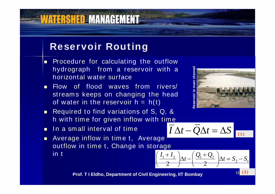
Reservoir Routing Procedure for calculating the outflow
hydrograph from a reservoir with ah i t l t f an
nel
anne
l
horizontal water surface Flow of flood waves from rivers/
streams keeps on changing the head oir
in m
ain
cha
oir
in m
ain
cha
p g gof water in the reservoir h = h(t)
Required to find variations of S, Q, & h with time for given inflow with time
Res
ervo
Res
ervo
h with time for given inflow with time In a small interval of time Average inflow in time t, Average
I t Q t S (1)g , g
outflow in time t, Change in storage in t 1 2 1 2
2 12 2I I Q Qt t S S
1212Prof. T I Eldho, Department of Civil Engineering, IIT Bombay
2 2 (2)

Reservoir RoutingFor reservoir routing the following data should be known Elevation vs Storage
Elevation vs outflow discharge and hence storage vs Elevation vs outflow discharge and hence storage vs outflow discharge
Inflow hydrograph, and Initial values of inflow, outflow Q, and storage S at
time t = 0. ∆t must be shorter than the time of transit of the flood
wave through the reachVariety of methods- for reservoir routingPul’s method and Goodrich’s method
Inflow
Outflow
DischargePul s method and Goodrich s method
TimeBased on Chow et.al(1988)
1313Prof. T I Eldho, Department of Civil Engineering, IIT Bombay
Time
Storage
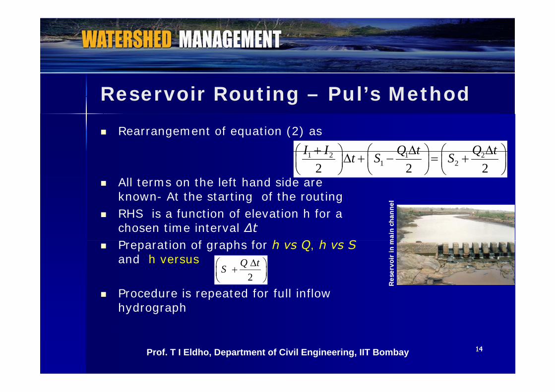
Reservoir Routing – Pul’s Method
Rearrangement of equation (2) asI I Q t Q t
All terms on the left hand side are known At the starting of the routing
1 2 1 21 22 2 2
I I Q t Q tt S S
known- At the starting of the routing RHS is a function of elevation h for a
chosen time interval ∆tP i f h f h Q h S m
ain
chan
nel
mai
n ch
anne
l
Preparation of graphs for h vs Q, h vs Sand h versus
2Q tS
Res
ervo
ir in
mR
eser
voir
in m
Procedure is repeated for full inflow hydrograph
RR
1414Prof. T I Eldho, Department of Civil Engineering, IIT Bombay
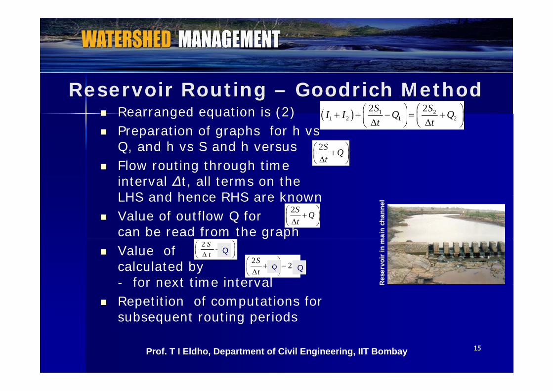
Reservoir Routing – Goodrich MethodR d i i (2) 2 2S S Rearranged equation is (2)
Preparation of graphs for h vs Q, and h vs S and h versus
1 21 2 1 2
2 2S SI I Q Qt t
2S Q Q, a d s S a d e sus
Flow routing through time interval ∆t, all terms on the LHS and hence RHS are known
Qt
LHS and hence RHS are known Value of outflow Q for
can be read from the graph
2S Qt
mai
n ch
anne
lm
ain
chan
nel
Value of calculated by - for next time interval
2 S Ot
Q
2 2S O Ot
Res
ervo
ir in
mR
eser
voir
in m
for next time interval Repetition of computations for
subsequent routing periods
RR
1515Prof. T I Eldho, Department of Civil Engineering, IIT Bombay
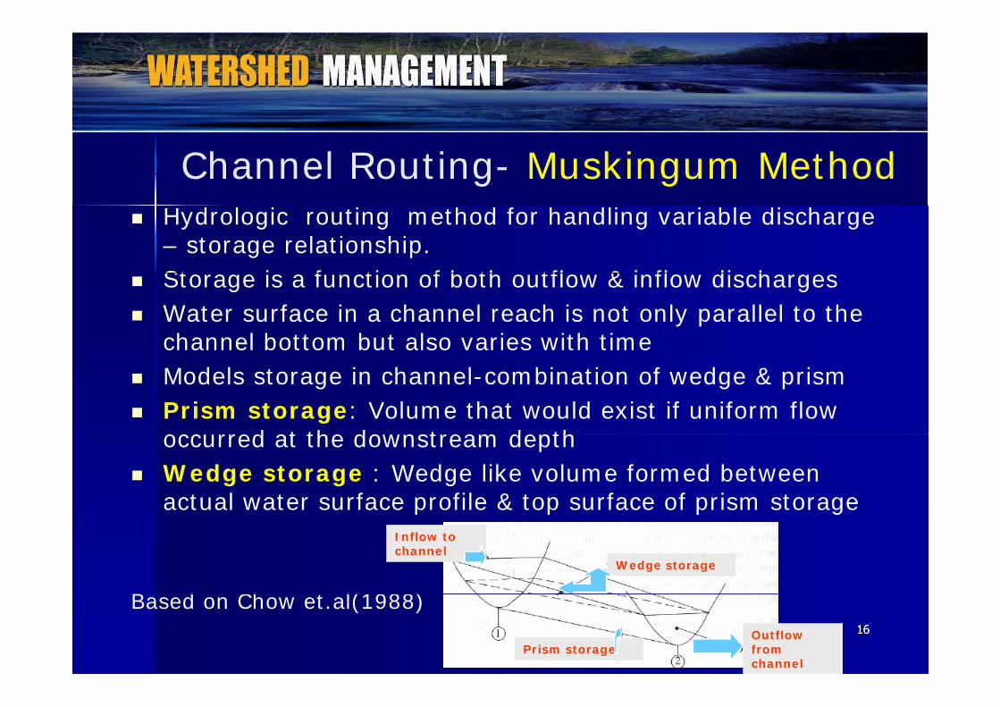
Channel Routing- Muskingum Method Hydrologic routing method for handling variable discharge
– storage relationship.St i f ti f b th tfl & i fl di h Storage is a function of both outflow & inflow discharges
Water surface in a channel reach is not only parallel to the channel bottom but also varies with time
Models storage in channel-combination of wedge & prism Prism storage: Volume that would exist if uniform flow
o ed at the do nst eam depthoccurred at the downstream depth Wedge storage : Wedge like volume formed between
actual water surface profile & top surface of prism storagep p p gInflow to channel
Wedge storage
B d Ch t l(1988)1616Outflow
from channel
Prism storage
Based on Chow et.al(1988)

Channel Routing- Muskingum Method
During the advance of flood wave, inflow exceeds outflow –Positive wedgePositive wedge
During recession, outflow exceeds inflow –Negative wedge Assumption: Cross sectional area of the flood flow section is
d l l h d h hdirectly proportional to the discharge at the section Volume of prism storage is equal to KO Volume of the wedge storage is equal to KX(I - O) Volume of the wedge storage is equal to KX(I O) K – proportionality coefficient, X -weighing factor having
the range 0 < X < 0.5
Wedge storage = KX(I-O)
Based on Chow et.al(1988)
Inflow to channel
1717Prof. T I Eldho, Department of Civil Engineering, IIT BombayPrism storage=KO
( )
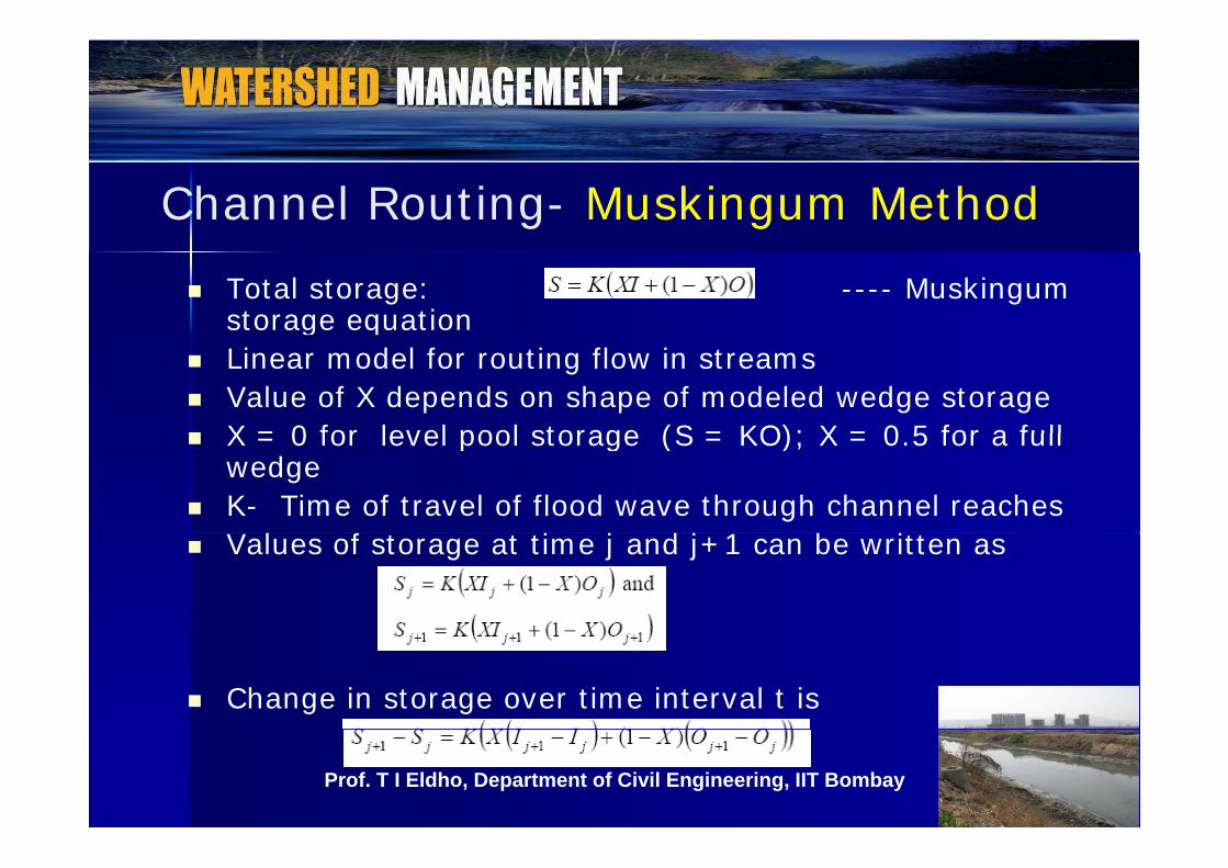
Channel Routing- Muskingum Method Total storage: ---- Muskingum
storage equationg q Linear model for routing flow in streams Value of X depends on shape of modeled wedge storage X = 0 for level pool storage (S = KO); X = 0 5 for a full X = 0 for level pool storage (S = KO); X = 0.5 for a full
wedge K- Time of travel of flood wave through channel reaches
l f d b Values of storage at time j and j+1 can be written as
Change in storage over time interval t is
1818Prof. T I Eldho, Department of Civil Engineering, IIT Bombay
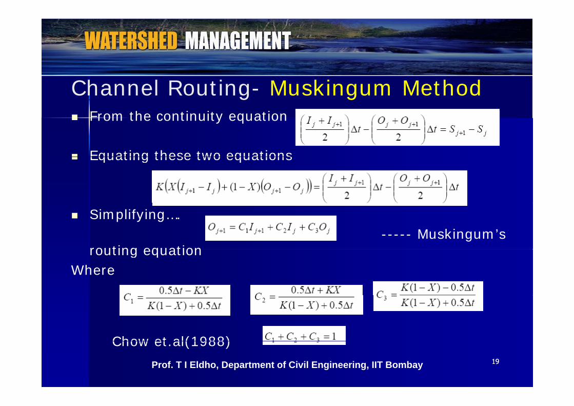
Channel Routing- Muskingum MethodF h i i i From the continuity equation
Equating these two equations Equating these two equations
Simplifying….----- Muskingum’s
routing equationrouting equationWhere
Chow et al(1988)1919
Chow et.al(1988)Prof. T I Eldho, Department of Civil Engineering, IIT Bombay
Channel Routing- Muskingum Method ∆ t should be so chosen that K > t > 2KX ….. For best
results If ∆ t < 2KX ……. Coefficient C1 will be negativeRequired input for Muskingum routing Inflow hydrograph through a channel reach, Inflow hydrograph through a channel reach, Values of K and X for the reach Value of the outflow Oj from the reach at the start
F i h l h K & X t k For a given channel reach, K & X are taken as constant
K is determined empirically (eg. Clark’s method: 0 5K=cL/s0.5; c – constant; L – length of stream,; s –
mean slope of channel) or graphically. X is determined by trial and error procedure
2020
y p
Prof. T I Eldho, Department of Civil Engineering, IIT Bombay
Muskingum Method - Procedure
Routing Procedure:
Knowing K and X, select an appropriate value of ∆ t
Calculate C1, C2, and C3
S f h l d k fl Starting from the initial conditions known inflow, outflow, calculate the outflow for the next time step
Repeat the calculations for the entire inflow hydrograph
2121Prof. T I Eldho, Department of Civil Engineering, IIT Bombay
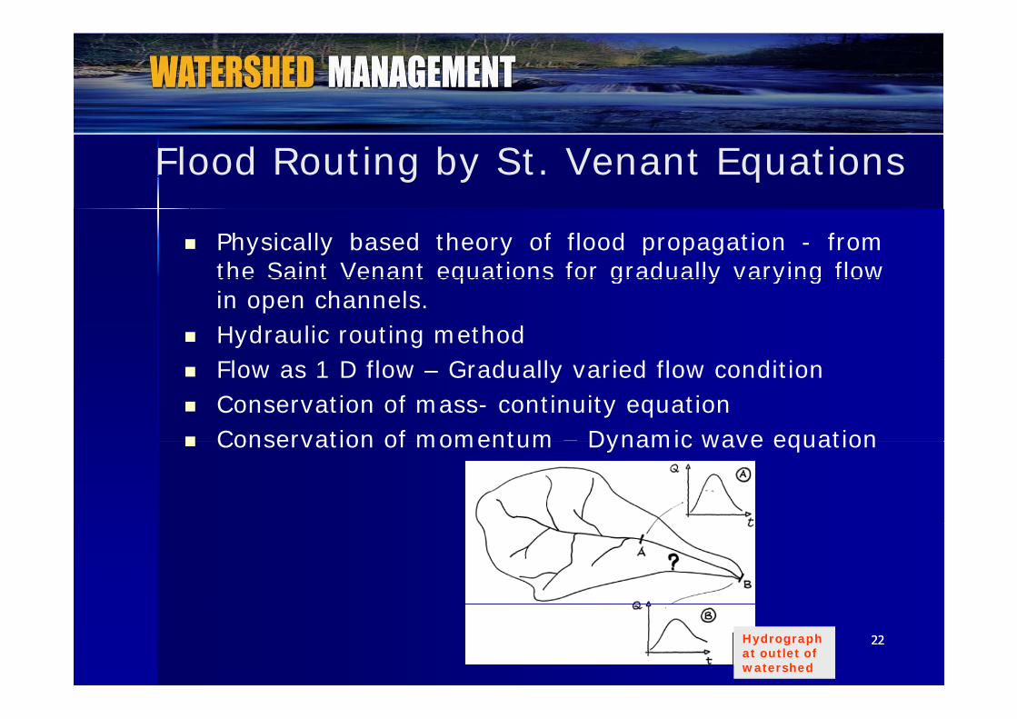
Flood Routing by St. Venant Equations
Physically based theory of flood propagation - fromthe Saint Venant equations for gradually varying flowthe Saint Venant equations for gradually varying flowin open channels.
Hydraulic routing methodl fl d ll d fl d Flow as 1 D flow – Gradually varied flow condition
Conservation of mass- continuity equation Conservation of momentum – Dynamic wave equation Conservation of momentum Dynamic wave equation
2222Hydrograph at outlet of watershed
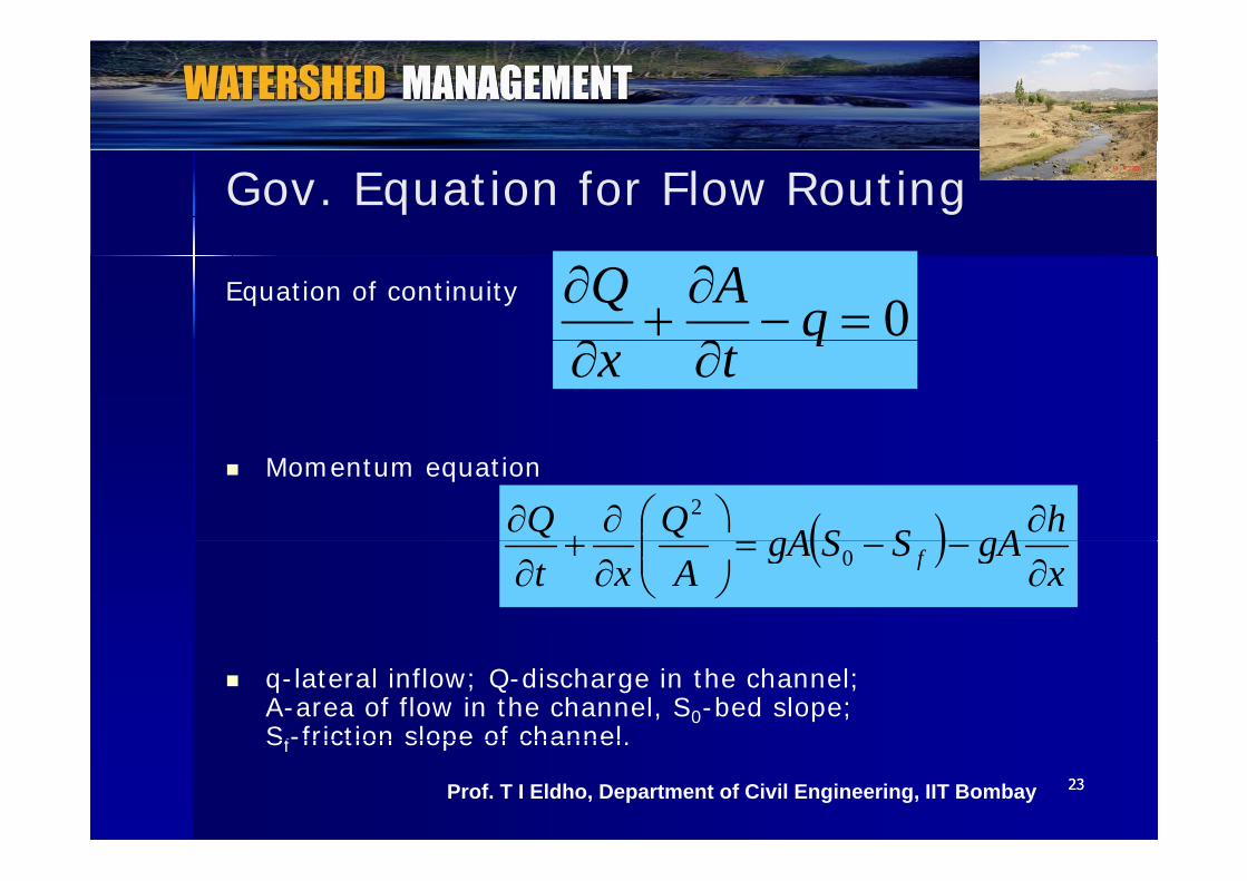
Gov. Equation for Flow Routing
Equation of continuity0
qAQ
q
tx
Momentum equation
hgASSgAQQ
2
x
gASSgAAxt f
0
q-lateral inflow; Q-discharge in the channel; A-area of flow in the channel, S0-bed slope; Sf-friction slope of channel
2323
Sf friction slope of channel.
Prof. T I Eldho, Department of Civil Engineering, IIT Bombay

Channel Flow- Diffusion & KinematicKinematic Diffusion h0
qAQ
Initial conditions B d diti
fo SSxh
2/13/21
q
tx
Boundary conditions
Kinematic:
ASRn
Q fh2/13/21
Kinematic:S0=Sf 0
q
tA
xQ
2424Prof. T I Eldho, Department of Civil Engineering, IIT Bombay
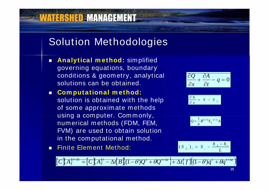
Solution Methodologies Analytical method: simplified
governing equations, boundary diti & t l ti l conditions & geometry, analytical
solutions can be obtained. Computational method:
0
q
tA
xQ
psolution is obtained with the help of some approximate methods using a computer. Commonly,
cfh S Sx
using a computer. Commonly, numerical methods (FDM, FEM, FVM) are used to obtain solution in the computational method
(2 /3) (1/ 2)1cf
Q R S An
in the computational method. Finite Element Method:
ttttttttt fQQBACAC )1()1(
( )c i
k if i
h hS SL
2525
ttttttttt qqftQQBtACAC )1()1(
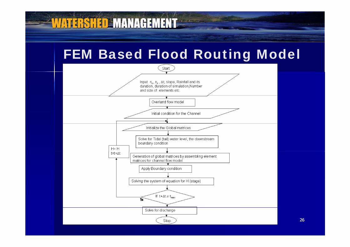
FEM Based Flood Routing Model
2626
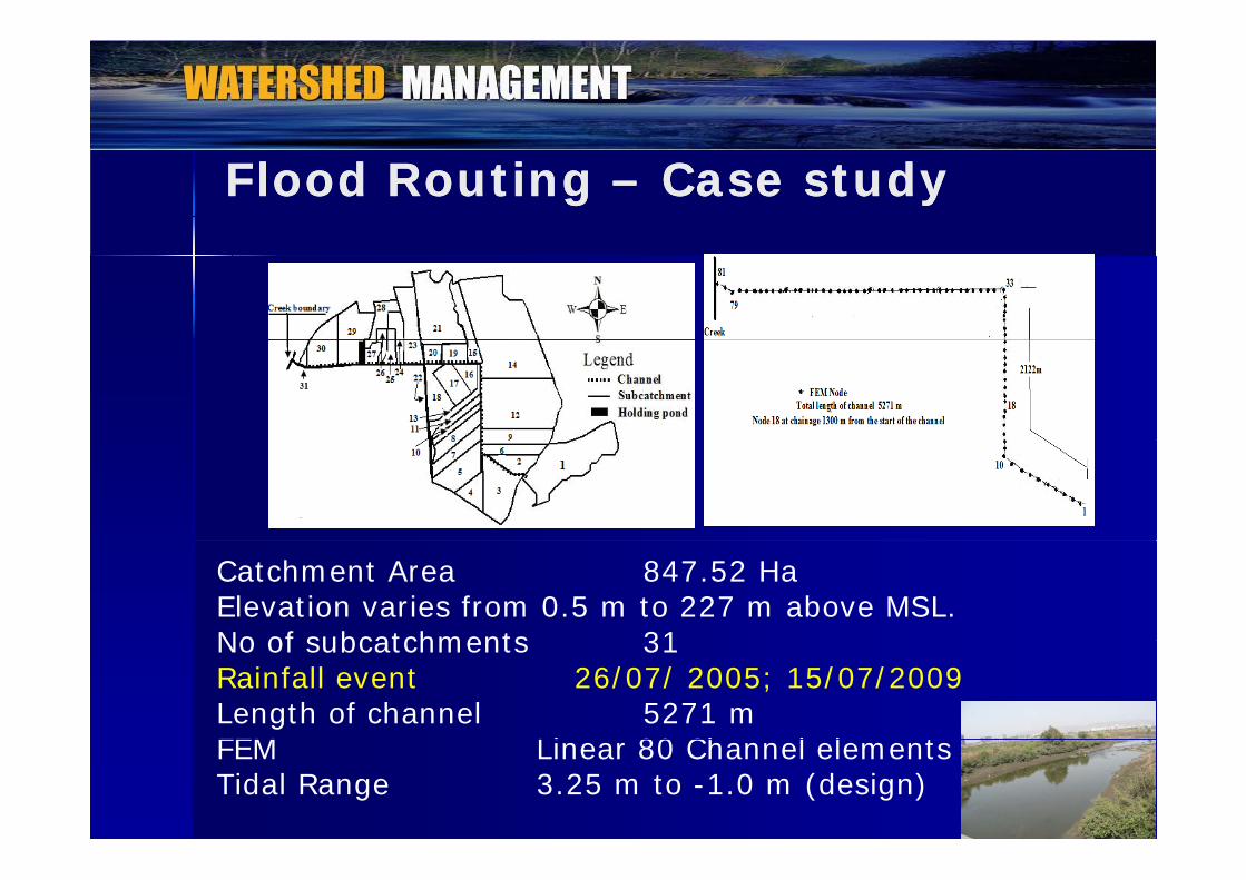
Flood Routing Flood Routing –– Case studyCase study
Catchment Area 847.52 HaElevation varies from 0.5 m to 227 m above MSL. No of subcatchments 31No of subcatchments 31Rainfall event 26/07/ 2005; 15/07/2009Length of channel 5271 mFEM Li 80 Ch l l t
2727
FEM Linear 80 Channel elementsTidal Range 3.25 m to -1.0 m (design)
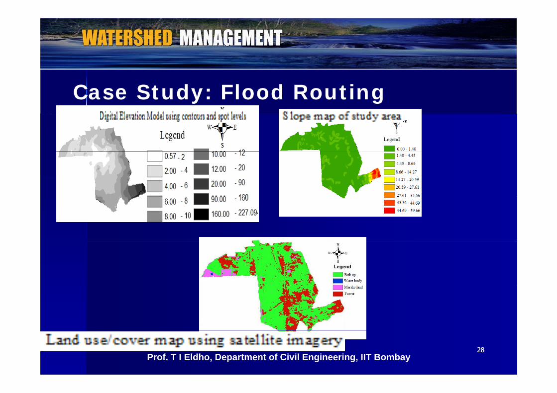
Case Study: Flood Routing
2828Prof. T I Eldho, Department of Civil Engineering, IIT Bombay

Case Study: Flood Routing
60
80
100
Hytograph of Kalamboli rainfall
︵mm
/hr
︶ Hyetograph 26/07/2005
12 13 14 15 16 17 18 19 20 21 22 23 240
20
40
Rai
nfal
l
Time starting from 12 hr ︵hr ︶
2929
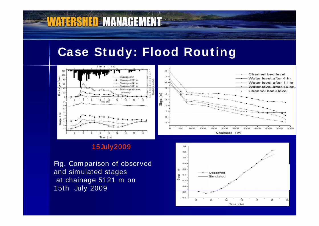
Case Study: Flood Routing
15July200915July2009
Fig Comparison of observed Fig. Comparison of observed and simulated stagesat chainage 5121 m on 15th July 2009
3030
15th July 2009
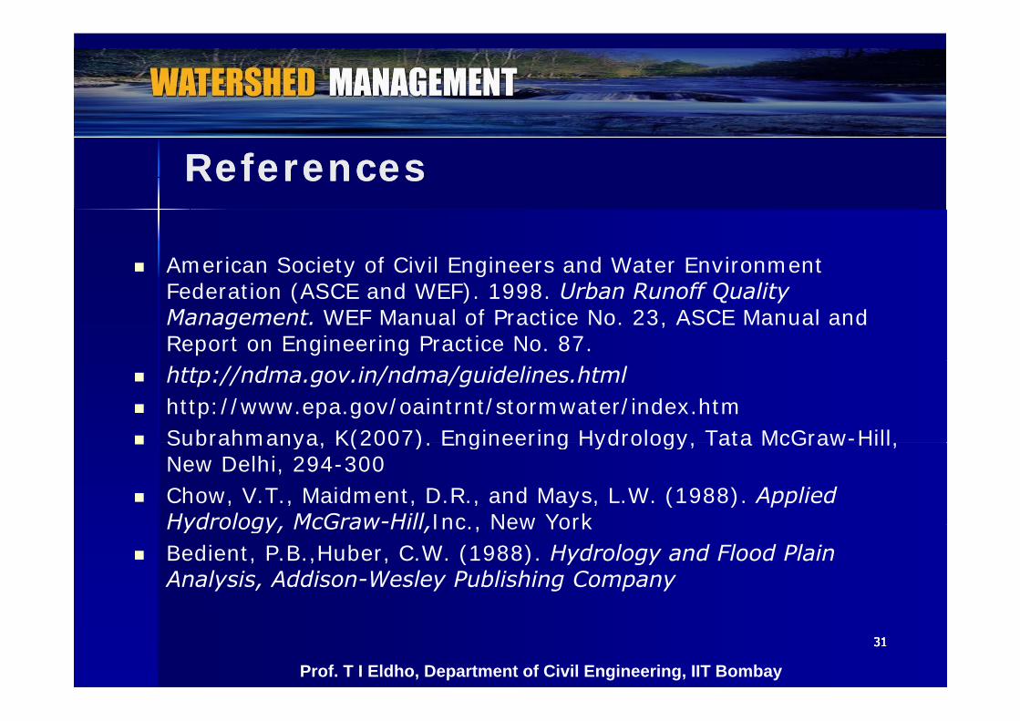
ReferencesReferences
American Society of Civil Engineers and Water Environment Federation (ASCE and WEF). 1998. Urban Runoff Quality Management. WEF Manual of Practice No. 23, ASCE Manual and Report on Engineering Practice No. 87.
http://ndma.gov.in/ndma/guidelines.html http://www.epa.gov/oaintrnt/stormwater/index.htm Subrahmanya, K(2007). Engineering Hydrology, Tata McGraw-Hill, Subrahmanya, K(2007). Engineering Hydrology, Tata McGraw Hill,
New Delhi, 294-300 Chow, V.T., Maidment, D.R., and Mays, L.W. (1988). Applied
Hydrology McGraw-Hill Inc New YorkHydrology, McGraw Hill,Inc., New York Bedient, P.B.,Huber, C.W. (1988). Hydrology and Flood Plain
Analysis, Addison-Wesley Publishing Company
31313131
Prof. T I Eldho, Department of Civil Engineering, IIT Bombay
Tutorials - Question!.?. Study the various flood routing
methodologies in details and suggest methodologies in details and suggest applications of each.
What are the software available for flood What are the software available for flood routing?. (routing?. (www.hec.usace.army.milwww.hec.usace.army.mil )Evaluate the applications for various Evaluate the applications for various problems such as reservoir routing/ channel problems such as reservoir routing/ channel routing.routing.
32323232
Prof. T I Eldho, Department of Civil Engineering, IIT Bombay
Self Evaluation - Questions!.
What is flood routing and where it is used?E l i i ti Explain reservoir routing.
Differentiate between Pul’s method & Goodrich methodmethod.
Describe the Muskingum method of flood routing.Describe the prism storage & wedge storage in a Describe the prism storage & wedge storage in a channel.
What are the input data required for Muskingum What are the input data required for Muskingum routing?.
33333333Prof. T I Eldho, Department of Civil Engineering, IIT Bombay
Assignment- Questions?.g Q What are the motivations for flood routing?. Describe different types and advantages of Describe different types and advantages of
flood routing. Illustrate the channel routing procedure Illustrate the channel routing procedure. Describe the lumped flow routing.
Di h i ll b d fl d ti i Discuss physically based flood routing in channels by using St. Venant equations.
34343434Prof. T I Eldho, Department of Civil Engineering, IIT Bombay
Dr. T. I. EldhoDr. T. I. EldhoProfessor,Professor,Department of Civil Engineering, Department of Civil Engineering, p g gp g gIndian Institute of Technology Bombay,Indian Institute of Technology Bombay,Mumbai, India, 400 076.Mumbai, India, 400 076.Email:Email: [email protected]@iitb.ac.in
3535
Email: Email: [email protected]@iitb.ac.inPhone: (022) Phone: (022) –– 25767339; Fax: 2576730225767339; Fax: 25767302http://www.http://www.civil.iitb.ac.incivil.iitb.ac.in