Module 4 NOISE IN COMMUNICATION CHANNELS. – Any electrical signal transmitted from one point to...
38
Module 4 NOISE IN COMMUNICATION CHANNELS
-
Upload
kathlyn-reeves -
Category
Documents
-
view
219 -
download
0
Transcript of Module 4 NOISE IN COMMUNICATION CHANNELS. – Any electrical signal transmitted from one point to...

Module 4
NOISE IN COMMUNICATION CHANNELS
– Any electrical signal transmitted from one point to another consist of the desirable part( original intelligence) and the undesirable part called noise.
– Noise is the undesirable part that interferes with the desirable part.
– Noise in communication originates both in the channel and communication equipments.
– Noise is a random signal that exists in a communication,
thus no message is received exactly as the sender intends because of the ever presence of noise in communication. Noise can be both external and internal.
– The effect of noise when superimposed on an information-bearing signal makes the message to be partially corrupted or totally destroyed.
– Noise cannot be avoided completely, but its effect can be reduced by filtering or by reducing the signal bandwidth.
– Noise constitutes one of the fundamental limiting factor in the performance of communication systems.

Sources of Noise
The sources of noise can be classified into two:• External Noise • Internal NoiseExternal Noise: This type of noise is introduced in the
communication medium, and often comes from sources we have little or no control over in our physical environment.
The two primary sources of external noise are:1. Natural Noise 2. Man Made noise
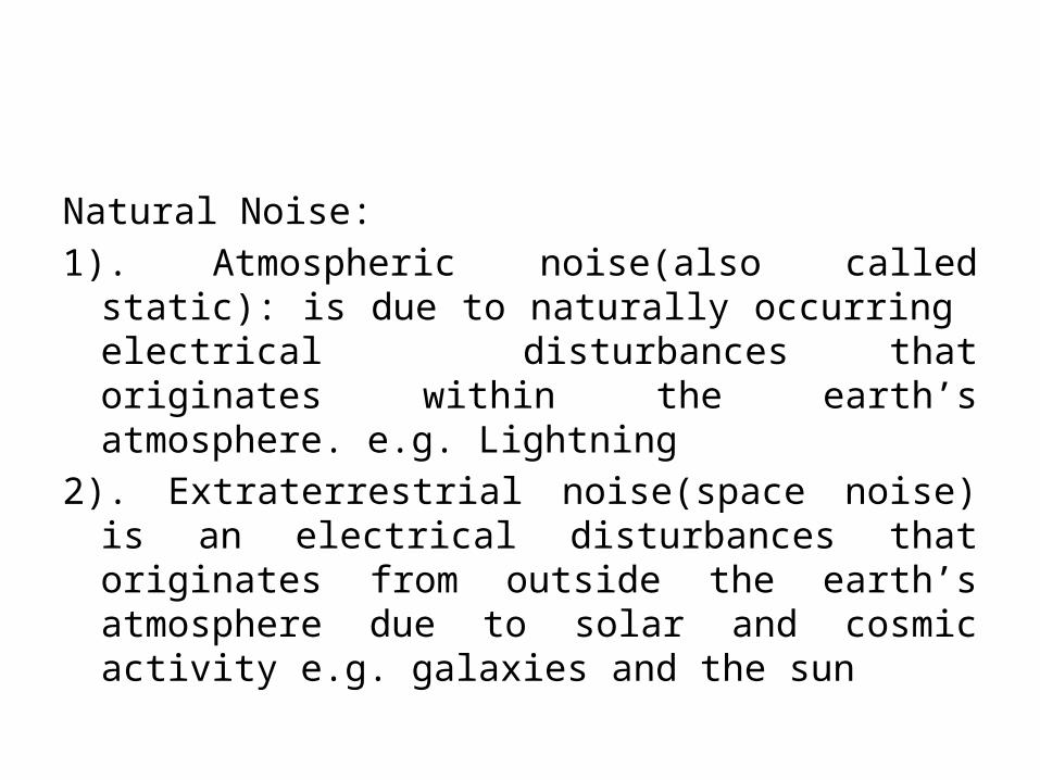
Natural Noise:1). Atmospheric noise(also called static): is due to naturally
occurring electrical disturbances that originates within the earth’s atmosphere. e.g. Lightning
2). Extraterrestrial noise(space noise) is an electrical disturbances that originates from outside the earth’s atmosphere due to solar and cosmic activity e.g. galaxies and the sun

3). Man made noise This is basically noise produced by mankind electrical
sources such as spark producing machineries from industries. It is usually more intense in industrial and highly populated areas.
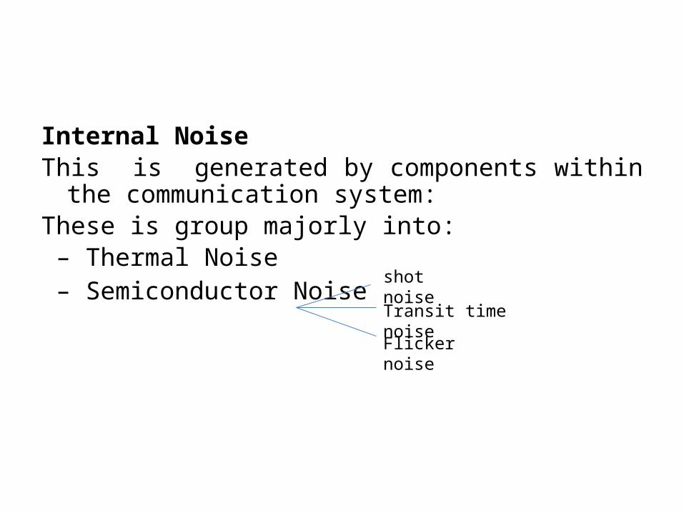
Internal NoiseThis is generated by components within the
communication system:These is group majorly into: – Thermal Noise – Semiconductor Noise
shot noise
Flicker noise
Transit time noise

1). Thermal noise This is caused by random motion of electrons in a
conductor due to heat.
Noise Power is directly proportional to Bandwidth(Hz), and the temperature (degrees Kelvin)
Pn α T.B Pn = K.T.B

– The movement of electrons forms Kinetic energy theory in a conductor. At any temperature above absolute zero, thermal energy causes microscopic particles to exhibit random motion.
– The random motion of charged particles generates random currents or voltages called thermal noise.
This type of noise is generated by all resistances e.g. resistor, semiconductor etc
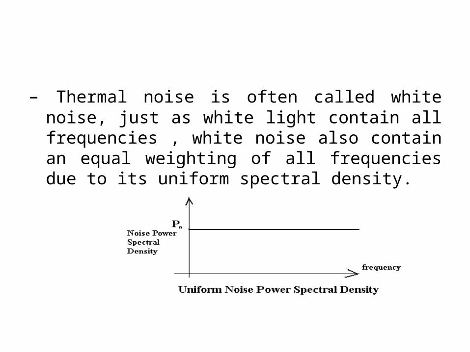
– Thermal noise is often called white noise, just as white light contain all frequencies , white noise also contain an equal weighting of all frequencies due to its uniform spectral density.
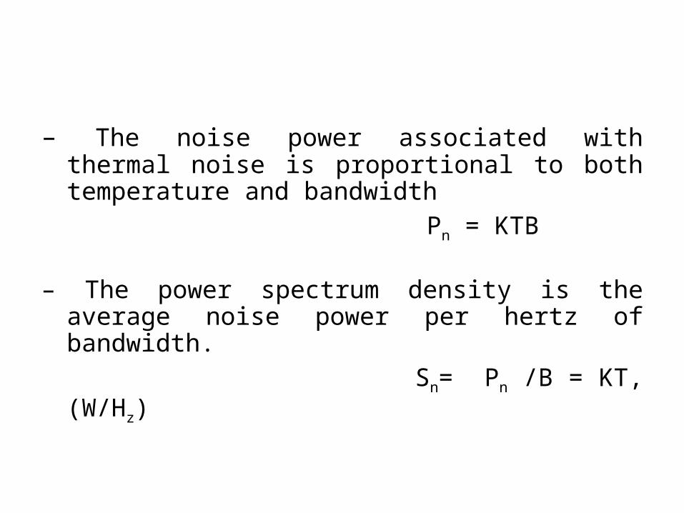
– The noise power associated with thermal noise is proportional to both temperature and bandwidth
Pn = KTB
– The power spectrum density is the average noise power per hertz of bandwidth.
Sn= Pn /B = KT, (W/Hz)
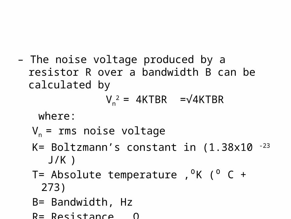
– The noise voltage produced by a resistor R over a bandwidth B can be calculated by
Vn2 = 4KTBR =√4KTBR
where:Vn = rms noise voltage
K= Boltzmann’s constant in (1.38x10 -23 J/K ) T= Absolute temperature ,⁰K (⁰ C + 273)B= Bandwidth, Hz R= Resistance, Ω

Noise due to sources in series
– Resultant of Resistors in series is given by RS = R1 +R2 +R3 +...
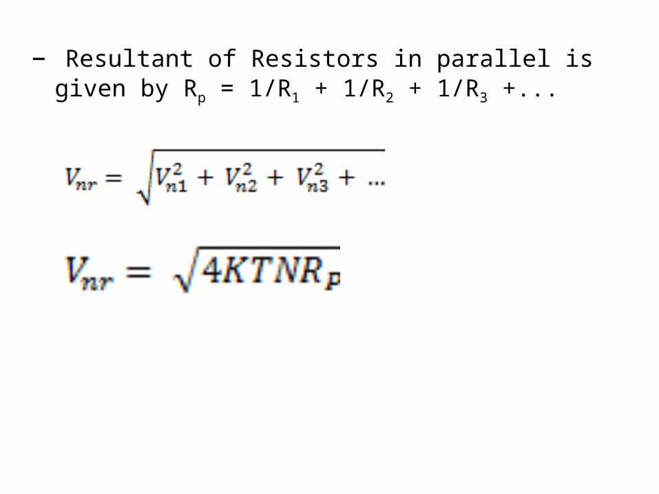
– Resultant of Resistors in parallel is given by Rp = 1/R1 + 1/R2 + 1/R3 +...
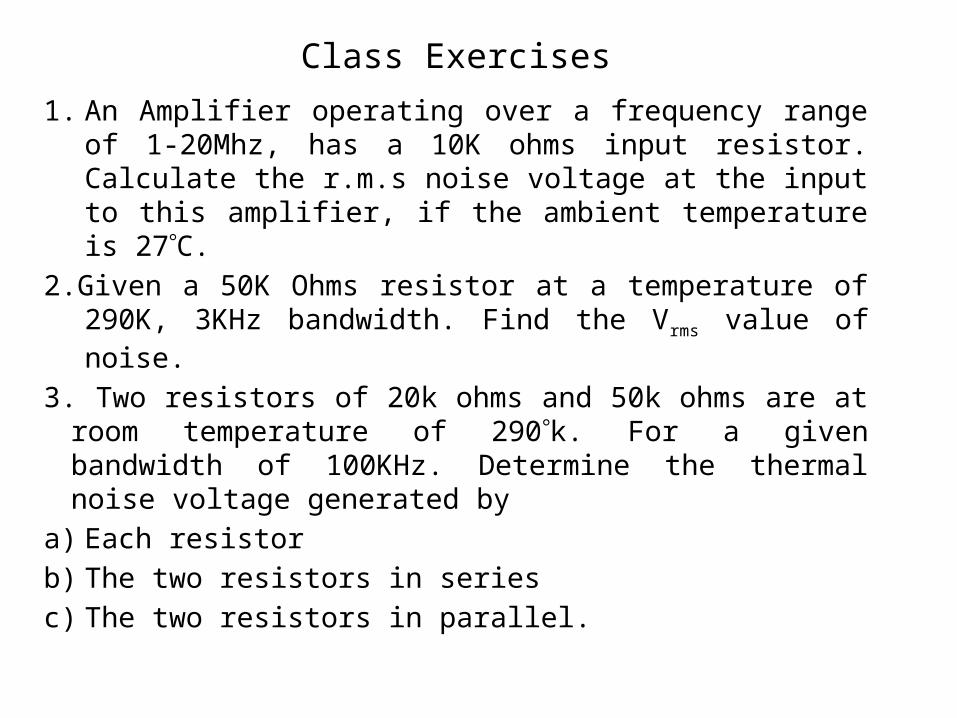
Class Exercises
1. An Amplifier operating over a frequency range of 1-20Mhz, has a 10K ohms input resistor. Calculate the r.m.s noise voltage at the input to this amplifier, if the ambient temperature is 27C.
2.Given a 50K Ohms resistor at a temperature of 290K, 3KHz bandwidth. Find the Vrms value of noise.
3. Two resistors of 20k ohms and 50k ohms are at room temperature of 290k. For a given bandwidth of 100KHz. Determine the thermal noise voltage generated by
a) Each resistorb) The two resistors in seriesc) The two resistors in parallel.
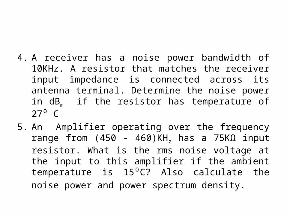
4. A receiver has a noise power bandwidth of 10KHz. A resistor that matches the receiver input impedance is connected across its antenna terminal. Determine the noise power in dBm if the resistor has temperature of 27⁰ C
5. An Amplifier operating over the frequency range from (450 - 460)KHz has a 75KΩ input resistor. What is the rms noise voltage at the input to this amplifier if the ambient temperature is 15⁰C? Also calculate the noise power and power spectrum density.
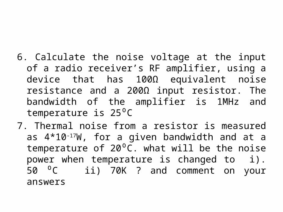
6. Calculate the noise voltage at the input of a radio receiver’s RF amplifier, using a device that has 100Ω equivalent noise resistance and a 200Ω input resistor. The bandwidth of the amplifier is 1MHz and temperature is 25⁰C
7. Thermal noise from a resistor is measured as 4*10-17W, for a given bandwidth and at a temperature of 20⁰C. what will be the noise power when temperature is changed to i). 50 ⁰C ii) 70K ? and comment on your answers

2). Semiconductor NoiseThese type of internal noise originates from
semiconductor devices such as diodes and transistors– Shot noise is a type of electronic noise that occurs due
to the random variation of current flowing in semiconductors such as transistors and diodes.
Shot noise has a uniform spectral density similar to thermal noise, and the mean square noise current
depends directly on the direct component of current.

To calculate shot noise in a diodewherein = rms shot noise current
q = charge of an electron 1.6 *10-19Cidc=dc current flowing through the device, Amperes
= frequency bandwidth of the system, Hz – Transit Time noise occur at high frequencies when the time
required to cross the semiconductor junction is close to the period of the signal
– Flicker Noise results from a minute variation in the resistance in semiconductor material.
fqIi dcn 2
f
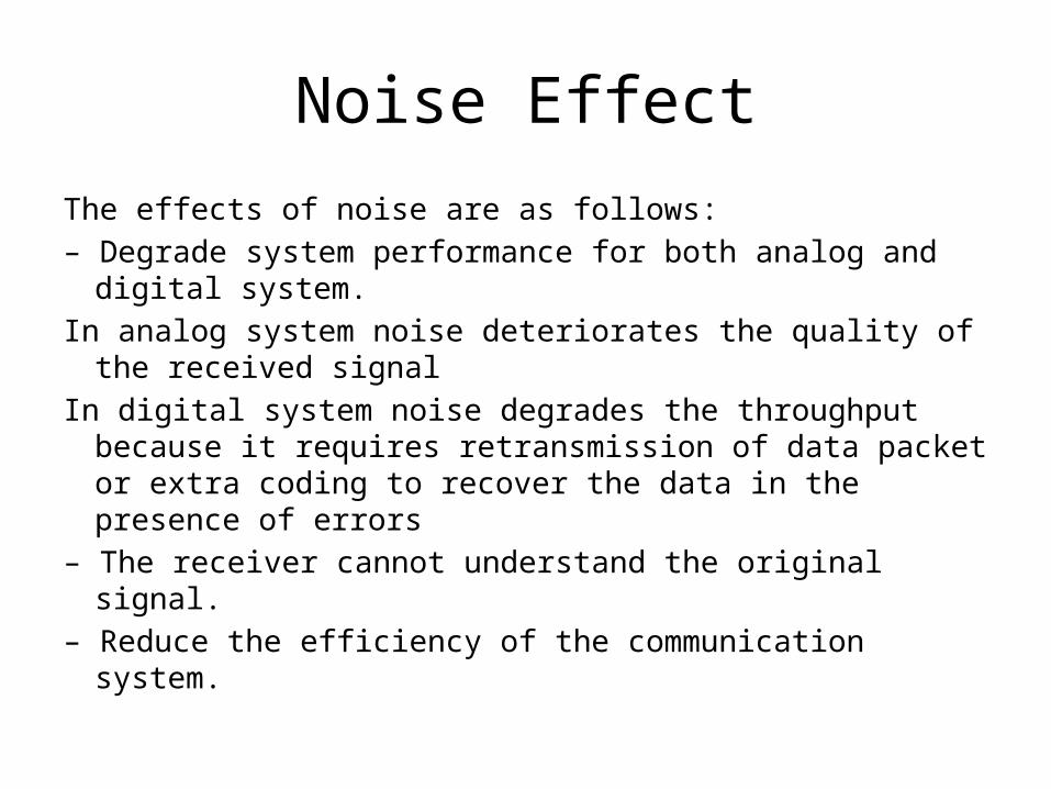
Noise Effect
The effects of noise are as follows:– Degrade system performance for both analog and digital
system.In analog system noise deteriorates the quality of the
received signal In digital system noise degrades the throughput because it
requires retransmission of data packet or extra coding to recover the data in the presence of errors
– The receiver cannot understand the original signal.– Reduce the efficiency of the communication system.
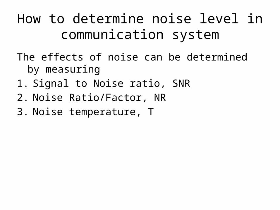
How to determine noise level in communication system
The effects of noise can be determined by measuring1. Signal to Noise ratio, SNR 2. Noise Ratio/Factor, NR3. Noise temperature, T

Signal-to-Noise Ratio (SNR)
The two main reasons why we calculate equivalent noise of a device is
– to compare two devices in order to evaluate their performance
– to compare the signal and the noise at the same point to ensure that noise is not excessive
To determine the quality of received signal at the receiverSNR is used. i.e. to quantify the effect of noise on a signal
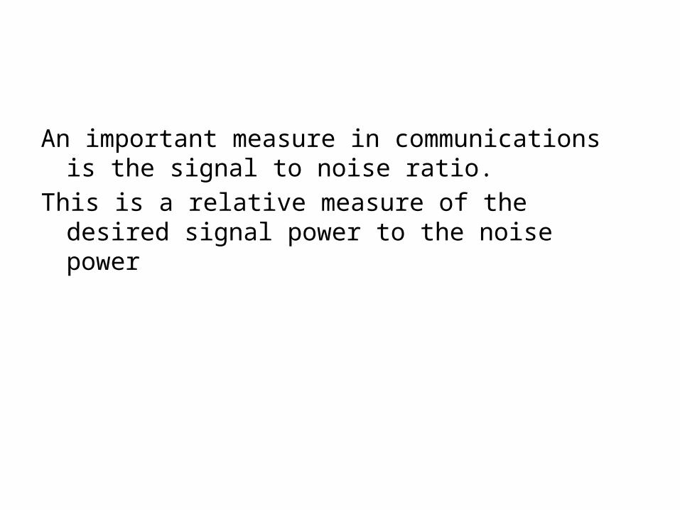
An important measure in communications is the signal to noise ratio.
This is a relative measure of the desired signal power to the noise power

• A strong signal and weak noise results in a High SNR • A weak signal and high noise results in Low SNR

Signal to Noise ratio can also be expressed in terms of voltages or power
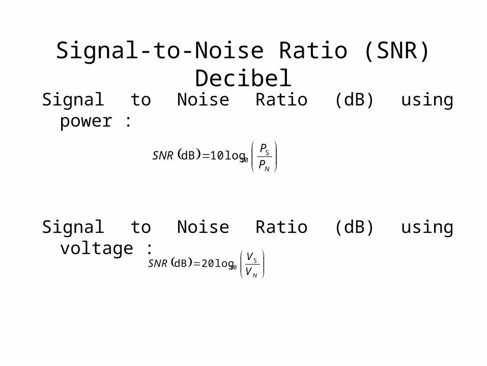
Signal-to-Noise Ratio (SNR) DecibelSignal to Noise Ratio (dB) using power :
Signal to Noise Ratio (dB) using voltage :
NP
PSNR S
10 log 10 dB
NV
VSNR S
10 log 20 dB
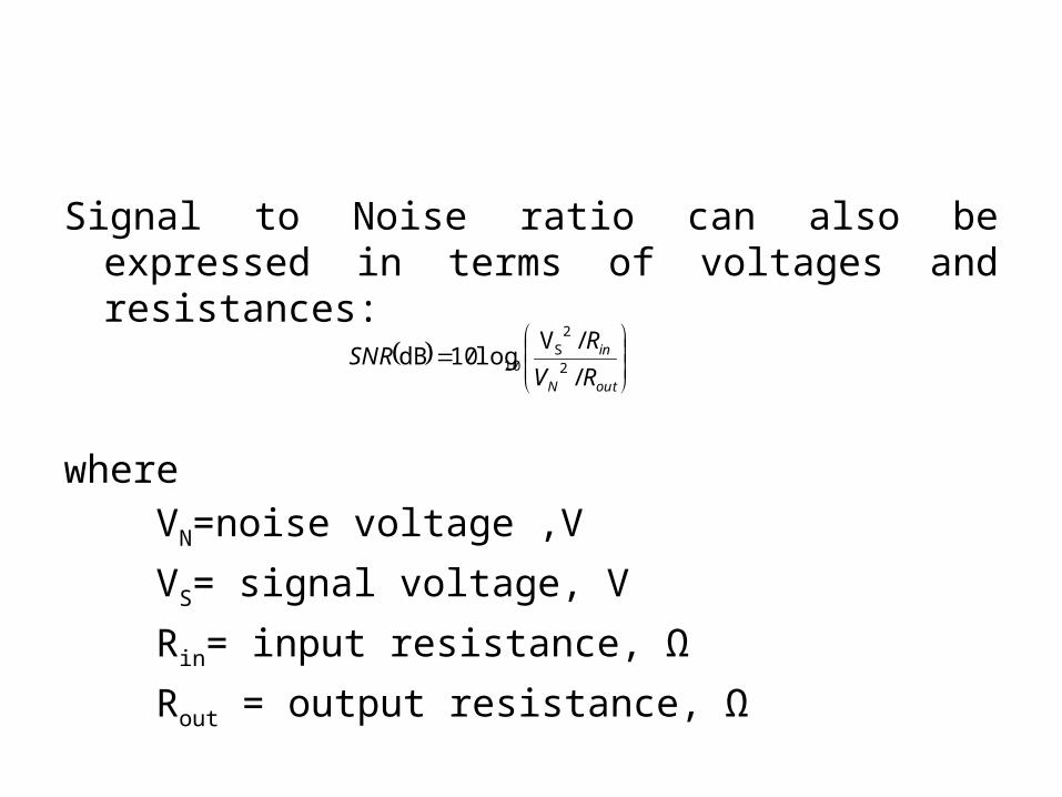
Signal to Noise ratio can also be expressed in terms of voltages and resistances:
where VN=noise voltage ,V
VS= signal voltage, V
Rin= input resistance, Ω
Rout = output resistance, Ω
outN
in
RV
RSNR
/
/V log 10 dB
2
2S
10
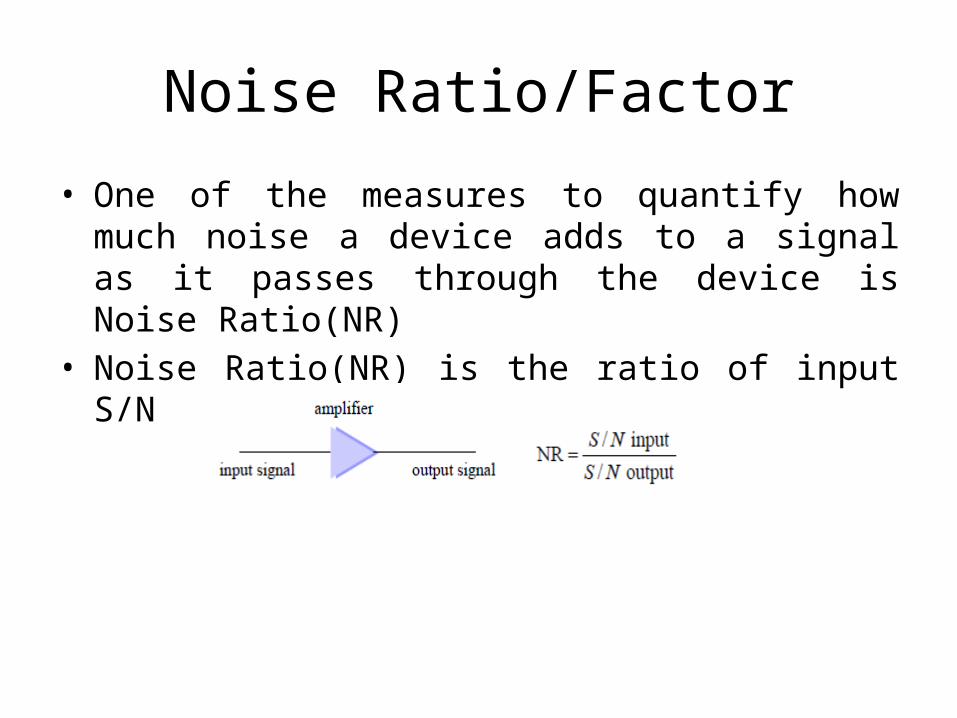
Noise Ratio/Factor
• One of the measures to quantify how much noise a device adds to a signal as it passes through the device is Noise Ratio(NR)
• Noise Ratio(NR) is the ratio of input S/N to output S/N
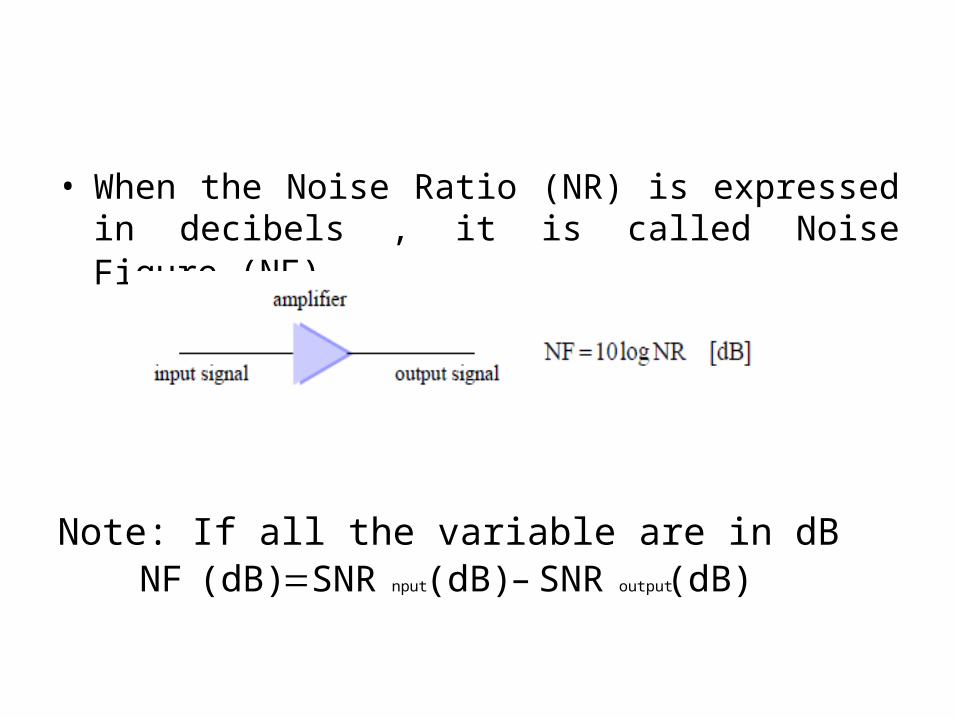
• When the Noise Ratio (NR) is expressed in decibels , it is called Noise Figure (NF).
Note: If all the variable are in dB
(dB)SNR– (dB)SNR (dB) NF output nput
Noise Temperature
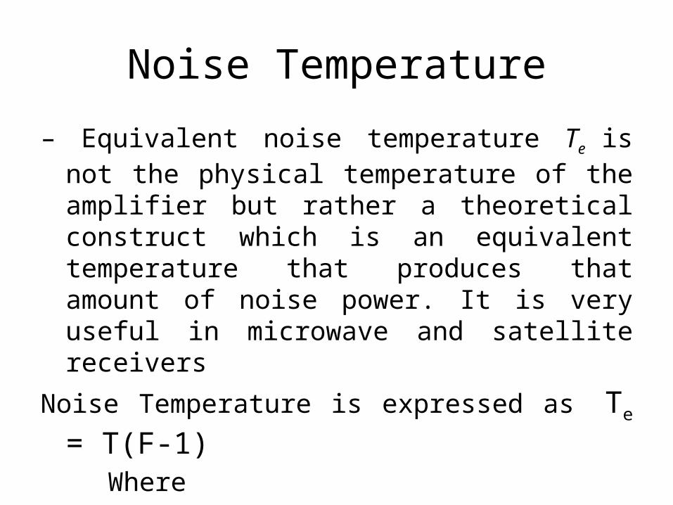
– Equivalent noise temperature Te is not the physical temperature of the amplifier but rather a theoretical construct which is an equivalent temperature that produces that amount of noise power. It is very useful in microwave and satellite receivers
Noise Temperature is expressed as Te = T(F-1)Where Te =equivalent noise temperature (K)
T =temperature reference value of 290KF =Noise Factor

• Bit Error Rate(BER) is used as a performance measure in digital communication systems
• Signal to Noise Ratio (SNR) is used as a performance measure in analog systems
Class Exercises
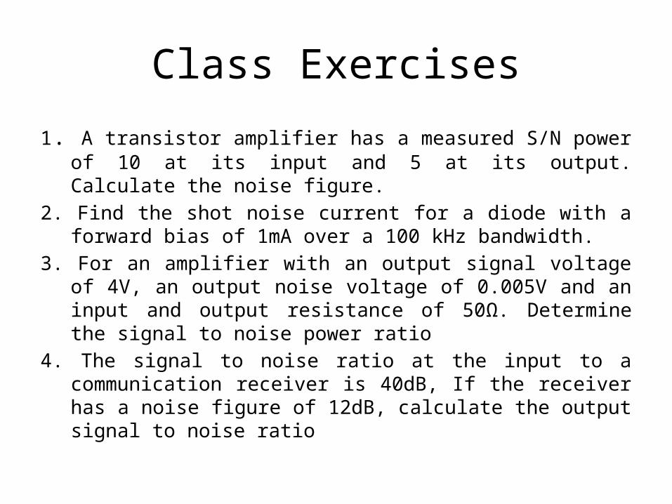
1. A transistor amplifier has a measured S/N power of 10 at its input and 5 at its output. Calculate the noise figure.
2. Find the shot noise current for a diode with a forward bias of 1mA over a 100 kHz bandwidth.
3. For an amplifier with an output signal voltage of 4V, an output noise voltage of 0.005V and an input and output resistance of 50Ω. Determine the signal to noise power ratio
4. The signal to noise ratio at the input to a communication receiver is 40dB, If the receiver has a noise figure of 12dB, calculate the output signal to noise ratio

Class Exercises (CONTD)
5. For an amplifier with an output signal power of 10W and output noise power of 0.01W. Determine the signal to noise power ratio.
6. A transistor amplifier has a measure S/N power ratio of 10,000 at its input and 5,624 at its output.
a) Calculate the Noise Ratio NRb) Calculate the Noise Figure F7. Calculate the shot noise component of the current present
on the direct current of 1mA flowing across a semiconductor junction, given that effective noise bandwidth is 1MHz.
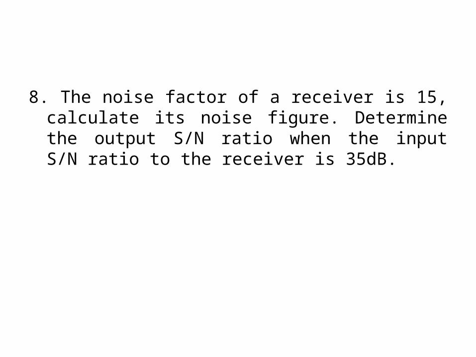
8. The noise factor of a receiver is 15, calculate its noise figure. Determine the output S/N ratio when the input S/N ratio to the receiver is 35dB.
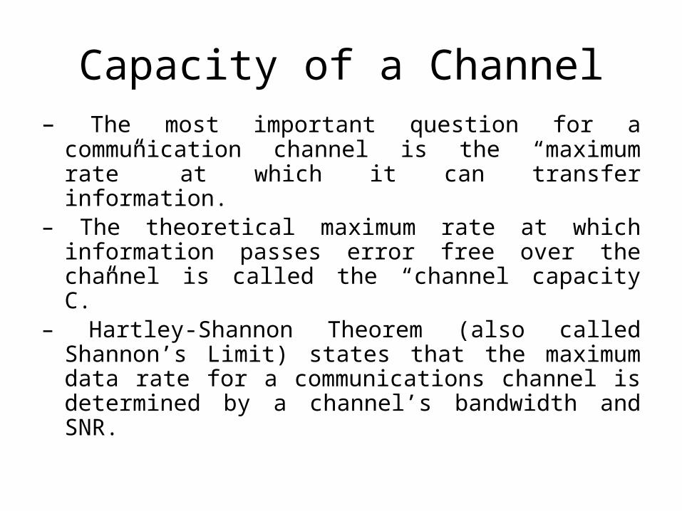
Capacity of a Channel– The most important question for a communication
channel is the “maximum rate” at which it can transfer information.
– The theoretical maximum rate at which information passes error free over the channel is called the “channel capacity C.”
– Hartley-Shannon Theorem (also called Shannon’s Limit) states that the maximum data rate for a communications channel is determined by a channel’s bandwidth and SNR.
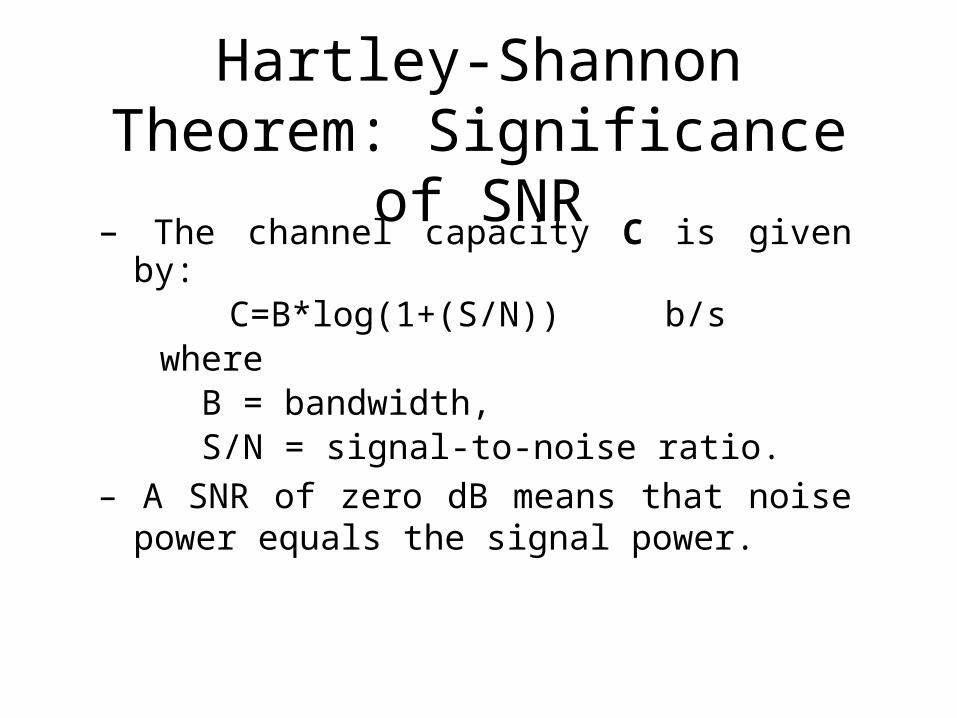
Hartley-Shannon Theorem: Significance of SNR
– The channel capacity C is given by: C=B*log(1+(S/N)) b/s
where B = bandwidth, S/N = signal-to-noise ratio.– A SNR of zero dB means that noise power equals
the signal power.
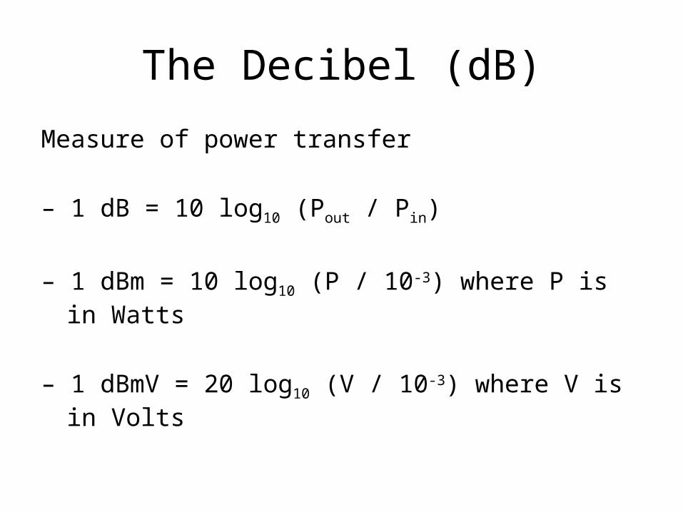
The Decibel (dB)
Measure of power transfer
– 1 dB = 10 log10 (Pout / Pin)
– 1 dBm = 10 log10 (P / 10-3) where P is in Watts
– 1 dBmV = 20 log10 (V / 10-3) where V is in Volts