Modulation of Digital Data: FSK - York University · Modulation of Digital Data: FSK FSK –...
15
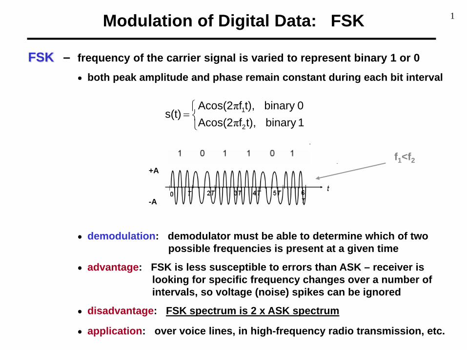
Modulation of Digital Data: FSK FSK – frequency of the carrier signal is varied to represent binary 1 or 0 • both peak amplitude and phase remain constant during each bit interval • demodulation: demodulator must be able to determine which of two possible frequencies is present at a given time • advantage: FSK is less susceptible to errors than ASK – receiver is looking for specific frequency changes over a number of intervals, so voltage (noise) spikes can be ignored • disadvantage: FSK spectrum is 2 x ASK spectrum • application: over voice lines, in high-frequency radio transmission, etc. = 1 binary t), f Acos(2 0 binary t), f Acos(2 s(t) 2 1 π π f 1 <f 2 +A -A 1
Transcript of Modulation of Digital Data: FSK - York University · Modulation of Digital Data: FSK FSK –...
Modulation of Digital Data: FSK
FSK – frequency of the carrier signal is varied to represent binary 1 or 0• both peak amplitude and phase remain constant during each bit interval
• demodulation: demodulator must be able to determine which of two possible frequencies is present at a given time
• advantage: FSK is less susceptible to errors than ASK – receiver islooking for specific frequency changes over a number ofintervals, so voltage (noise) spikes can be ignored
• disadvantage: FSK spectrum is 2 x ASK spectrum
• application: over voice lines, in high-frequency radio transmission, etc.
=1binary t),fAcos(20binary t),fAcos(2
s(t)2
1
ππ
f1<f2+A
-A
1

Modulation of Digital Data: FSK (cont.)
Example [ FSK ]
vd(t)
vc1(t)
vc2(t)
vFSK(t)
ω1 ωωd_max ω2ω1 ωω1-ωd_max
ω2 ω2+ωd_max
2

Modulation of Digital Data: FSK (cont.)
FSK-Modulated Signal: Frequency Spectrum
(t)vdDigital signal: - modulated with ω1 , and
- modulated with ω2
Modulated signal:
( ) ( )[ ]
( ) ( )[ ]
( ) ( )[ ]
( ) ( )[ ] ++++−+
++−−
++++−−
++−+=
=
=
−−+−⋅+
+
−+−+⋅=
=−⋅+⋅=
...t3ωωcost3ωωcos3π1
-tωωcostωωcosπ1tcosω
21
...t3ωωcost3ωωcos3π1
-tωωcostωωcosπ1tcosω
21
...tcos5ω5π2tcos3ω
3π2tcosω
π2
21tcosω
...tcos5ω5π2tcos3ω
3π2tcosω
π2
21tcosω
(t))vtcosω(t)vtcosω(t)v
0202
02022
0101
01011
0002
0001
d2d1FSK
...
1(
(t)v1-(t)'v dd =
3

PSK – phase of the carrier signal is varied to represent binary 1 or 0• peak amplitude and frequency remain constant during each bit interval
• example: binary 1 is represented with a phase of 0º, while binary 0is represented with a phase of 180º=πrad ⇒ PSK is equivalent to multiplying the carrier signal by +1 when the information is 1, and by-1 when the information is 0
• demodulation: demodulator must be able to determine the phase ofreceived sinusoid with respect to some reference phase
• advantage: PSK is less susceptible to errors than ASK, while itrequires/occupies the same bandwidth as ASK
more efficient use of bandwidth (higher data-rate) are possible, compared to FSK !!!
• disadvantage: more complex signal detection / recovery process, thanin ASK and FSK
+=
0binary ),tfAcos(21binary t),fAcos(2
s(t)c
c
πππ
Modulation of Digital Data: PSK
2-PSK, or Binary PSK,
since only 2 different phases
are used.
+A
-A
=0binary t),fAcos(2-1binary t),fAcos(2
s(t)c
c
ππ
4

Modulation of Digital Data: PSK (cont.)
Example [ PSK ]
vd(t)
vc(t)
vPSK(t)
ωc ωωd_max ωc ωωc+ωd_maxωc-ωd_max
5

Modulation of Digital Data: PSK (cont.)
PSK Detection / Recovery – multiply the received / modulated signalby 2*cos(2πfct)
• resulting signal
• by removing the oscillatory part with alow-pass filter, the original baseband signal(i.e. the original binary sequence) can beeasily determined
[ ] 1binary , t)fcos(41At)f(22Acos cc2 ππ +=
[ ] 0binary , t)fcos(41At)f(22Acos- cc2 ππ +−=
t)fAcos(2 cπ±( )2A cos1
21Acos2 +=
Ak = A, for binary 1Ak = -A, for binary 0
6

Modulation of Digital Data: PSK (cont.)
1 1 1 10 01 1 1 10 0Information
BasebandSignal
+A
-A0 T 2T 3T 4T 5T 6T
+A
-A0 T 2T 3T 4T 5T 6T
+A
-A0 T 2T 3T 4T 5T 6T
+A
-A0 T 2T 3T 4T 5T 6T
ModulatedSignal
x(t)
A cos(2πft) -A cos(2πft)
After multiplicationat receiver
x(t) cos(2πfct)
+A
-A0 T 2T 3T 4T 5T 6T
+A
-A0 T 2T 3T 4T 5T 6T
A {1 + cos(4πft)} -A {1 + cos(4πft)}
Basebandsignal discernable
after smoothing
+A
-A0 T 2T 3T 4T 5T 6T
sender
receiver
Signal shifted above / below zero level.
7
Modulation of Digital Data: PSK (cont.)
B
fc+B
f
ffc-B fc
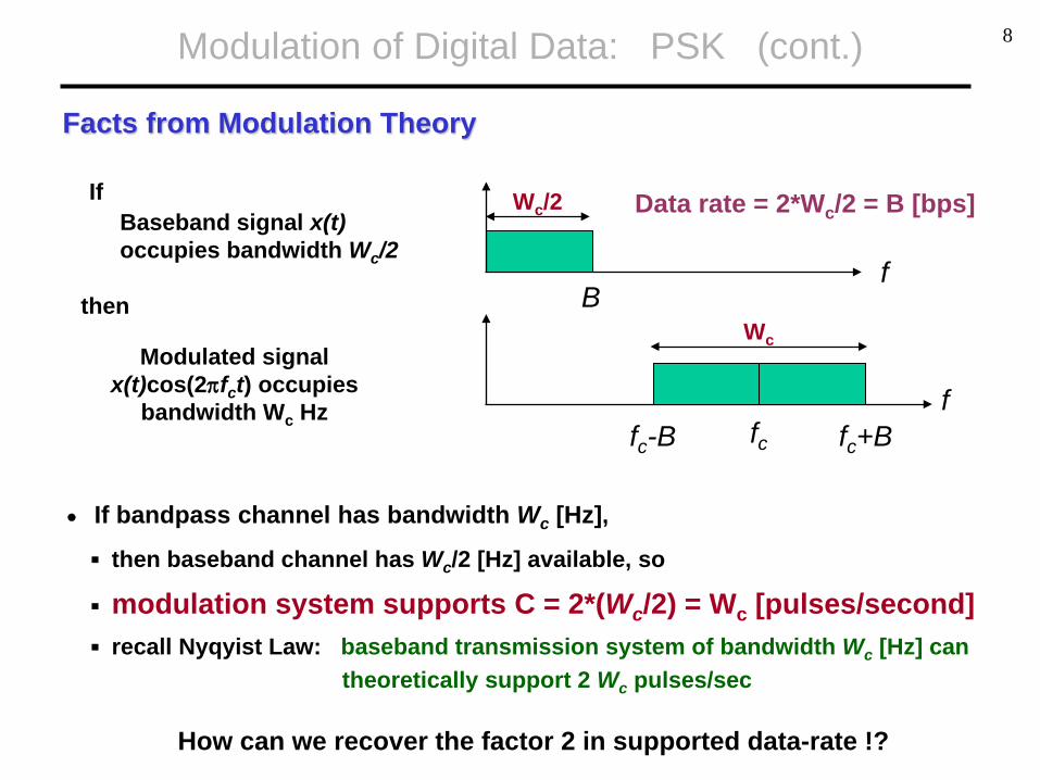
• If bandpass channel has bandwidth Wc [Hz],
then baseband channel has Wc/2 [Hz] available, so
modulation system supports C = 2*(Wc/2) = Wc [pulses/second] recall Nyqyist Law: baseband transmission system of bandwidth Wc [Hz] can
theoretically support 2 Wc pulses/sec
Facts from Modulation Theory
Wc
Wc/2Baseband signal x(t)occupies bandwidth Wc/2
If
then
Modulated signal x(t)cos(2πfct) occupies
bandwidth Wc Hz
How can we recover the factor 2 in supported data-rate !?
Data rate = 2*Wc/2 = B [bps]
8
Modulation of Digital Data: PSK (cont.)
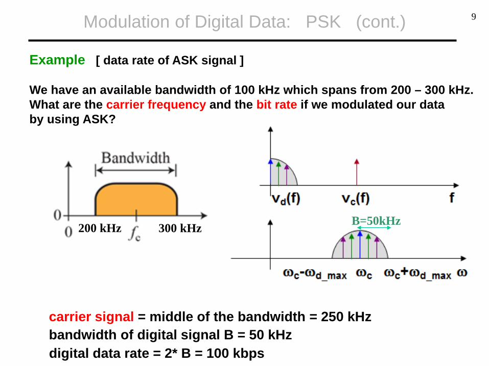
Example [ data rate of ASK signal ]
We have an available bandwidth of 100 kHz which spans from 200 – 300 kHz.What are the carrier frequency and the bit rate if we modulated our databy using ASK?
200 kHz 300 kHz
carrier signal = middle of the bandwidth = 250 kHzbandwidth of digital signal B = 50 kHzdigital data rate = 2* B = 100 kbps
B=50kHz
9

Example [ data rate of ASK signal ]
Assumptions are the same as in the previous example (200-300 kHzAvailable, for ASK modulated signal), but the line is full-duplex.
Modulation of Digital Data: PSK (cont.)
200 kHz 300 kHz
uplink downlink
bandwidth for uplink = bandwidth for downlink = 50 kHz
carrier for uplink = 225 kHz carrier for downlink = 275 kHz
bandwidth of digital signal = 25 kHz
digital data rate = 2* B = 50 kbps
10

Modulation of Digital Data: PSK (cont.)
Example [ data rate of FSK signal ]
Find the minimum bandwidth for FSK signal transmitting at 2000 bps using half-duplex mode, and the carriers are separated by 3000 Hz?
??? Hz
3000 Hz
overall bandwidth = band. dig. sig. + 3000 + band dig. sig. band. dig. sig. = C / 2 = 1000 Hzoverall bandwidth = 5000 Hz
11
Modulation of Digital Data: PSK (cont.)
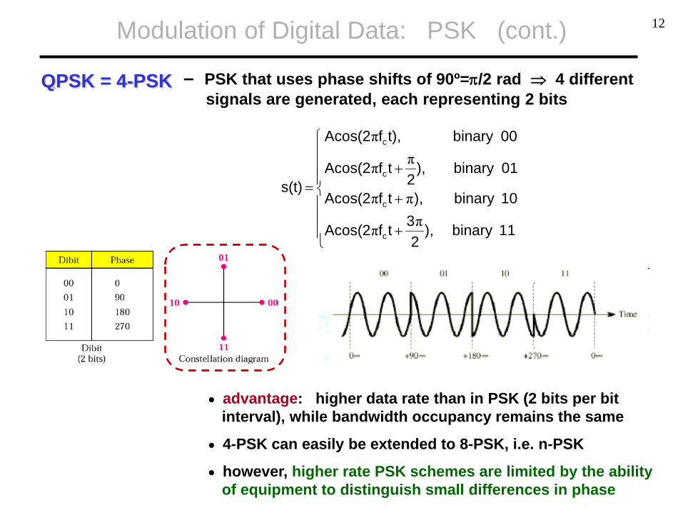
QPSK = 4-PSK – PSK that uses phase shifts of 90º=π/2 rad ⇒ 4 differentsignals are generated, each representing 2 bits
• advantage: higher data rate than in PSK (2 bits per bitinterval), while bandwidth occupancy remains the same
• 4-PSK can easily be extended to 8-PSK, i.e. n-PSK
• however, higher rate PSK schemes are limited by the abilityof equipment to distinguish small differences in phase
+
+
+=
11binary ),2
3tfAcos(2
10binary ),tfAcos(2
01binary ),2
tfAcos(2
00binary t),fAcos(2
s(t)
c
c
c
c
ππ
ππ
ππ
π
12

Signal Constellation
Constellation Diagram – used to represents possible symbols that maybe selected by a given modulation scheme aspoints in 2-D plane
• X-axis is related to in-phase carrier: cos(ωct) the projection of the point on the X-axis defines
the peak amplitude of the in-phase component
• Y-axis is related to the quadrature carrier: sin(ωct) the projection of the point on the Y-axis defines
the peak amplitude of the quadrature component
• the length of the line that connects the point to theorigin is the peak amplitude of the signal element(combination of X and Y components)
• the angle the line makes with the X-axis is the phase of the signal element
13
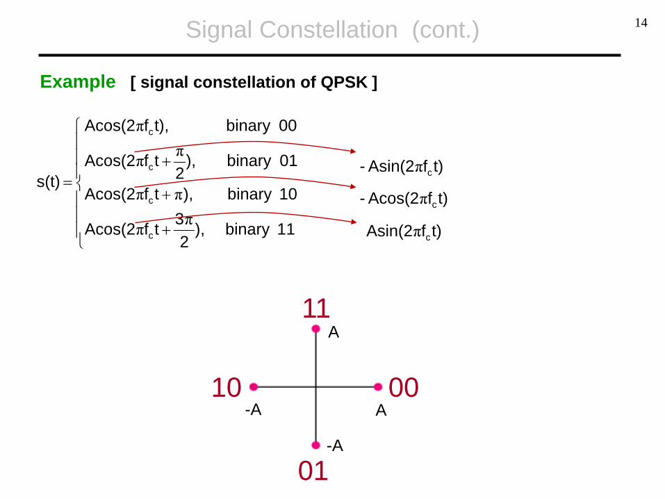
+
+
+=
11binary ),2
3tfAcos(2
10binary ),tfAcos(2
01binary ),2
tfAcos(2
00binary t),fAcos(2
s(t)
c
c
c
c
ππ
ππ
ππ
π
Signal Constellation (cont.)
Example [ signal constellation of QPSK ]
t)fAsin(2- cπ
t)fAcos(2- cπ
t)fAsin(2 cπ
00A-A
A
-A
01
10
11
14
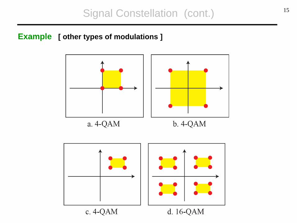
Signal Constellation (cont.)
Example [ other types of modulations ]
15