MODULATED HOMOGENEOUS FRICTION: A SEMI-ACTIVE DAMPING STRATEGY
16
EARTHQUAKE ENGINEERING AND STRUCTURAL DYNAMICS, VOL. 26, 361—376 (1997) MODULATED HOMOGENEOUS FRICTION: A SEMI-ACTIVE DAMPING STRATEGY JOSE¤ A. INAUDI* University of California at Berkeley and ARCH Ingenierı & a, Co & rdoba, Argentina SUMMARY A control strategy for semi-active friction devices leading to efficient hysteretic dissipaters is proposed. The control algorithm makes the contact force between the sliding surfaces of the damper proportional to the absolute value of the prior local peak of the damper deformation. This control logic leads to a non-linear force—deformation relation that satisfies homogeneity of degree one; this means that, like in a linear viscoelastic damping model, when the deformation is scaled by a constant, the force results are scaled by the same constant. The closed-loop system shows rectangular hysteresis loops which enclose an area proportional to the square of the deformation of the damper. Some characteristics of the dynamic response of structures incorporating this type of semi-active damper are investigated. It is demonstrated that in the case of single-degree-of-freedom models, the period of vibration and decay ratio are independent of the amplitude of vibration. In the case of multi-degree-of-freedom models with this type of nonlinearity, the free-vibration response can exhibit natural modes of vibration. A linearization method is proposed and modelling tools for the delay associated with actuator dynamics and for the flexibility of the brace connecting the damper to the structure are presented. KEY WORDS: damping; active control; friction; semi-active control; hysteretic damping 1. INTRODUCTION Variable-resistance dissipaters, also referred to as semi-active dampers in the literature, have been proposed as cost-efficient vibration-control systems for flexible structures. Semi-active viscous dampers and semi- active friction dampers have been utilized in suspension systems of automobiles1~3 and recently proposed for building structures or bridges subjected to earthquake excitation.4~13 Both variable viscous dampers and variable friction dampers can modulate the rate of energy dissipation by real-time adjustment of the damper resistance to deformation.2 Consider, for example, a variable viscous damper satisfying f (t)"c (t) d* dt (t) (1) where c (t) is the controllable damping constant (positive) and *(t) is the damper deformation. The energy dissipation rate is dE dt "c (t) A d* dt (t) B 2 *0 (2) where E (t) is the energy dissipated in the damper up to time t. As indicated in equation (1), by controlling c (t), the force in the damper can be controlled subject to the constraint in equation (2), and the damper can be *Research Engineer at University of California and Engineering Consultant at ARCH Ingenierı´ a, Argentina. CCC 0098—8847/97/030361—16 Received 22 February 1996 ( 1997 by John Wiley & Sons, Ltd. Revised 17 September 1996
Transcript of MODULATED HOMOGENEOUS FRICTION: A SEMI-ACTIVE DAMPING STRATEGY

EARTHQUAKE ENGINEERING AND STRUCTURAL DYNAMICS, VOL. 26, 361—376 (1997)
MODULATED HOMOGENEOUS FRICTION: A SEMI-ACTIVEDAMPING STRATEGY
JOSE A. INAUDI*
University of California at Berkeley and ARCH Ingenierı&a, Co& rdoba, Argentina
SUMMARY
A control strategy for semi-active friction devices leading to efficient hysteretic dissipaters is proposed. The controlalgorithm makes the contact force between the sliding surfaces of the damper proportional to the absolute value of theprior local peak of the damper deformation. This control logic leads to a non-linear force—deformation relation thatsatisfies homogeneity of degree one; this means that, like in a linear viscoelastic damping model, when the deformation isscaled by a constant, the force results are scaled by the same constant. The closed-loop system shows rectangularhysteresis loops which enclose an area proportional to the square of the deformation of the damper. Some characteristicsof the dynamic response of structures incorporating this type of semi-active damper are investigated. It is demonstratedthat in the case of single-degree-of-freedom models, the period of vibration and decay ratio are independent of theamplitude of vibration. In the case of multi-degree-of-freedom models with this type of nonlinearity, the free-vibrationresponse can exhibit natural modes of vibration. A linearization method is proposed and modelling tools for the delayassociated with actuator dynamics and for the flexibility of the brace connecting the damper to the structure arepresented.
KEY WORDS: damping; active control; friction; semi-active control; hysteretic damping
1. INTRODUCTION
Variable-resistance dissipaters, also referred to as semi-active dampers in the literature, have been proposedas cost-efficient vibration-control systems for flexible structures. Semi-active viscous dampers and semi-active friction dampers have been utilized in suspension systems of automobiles1~3 and recently proposed forbuilding structures or bridges subjected to earthquake excitation.4~13
Both variable viscous dampers and variable friction dampers can modulate the rate of energy dissipationby real-time adjustment of the damper resistance to deformation.2 Consider, for example, a variable viscousdamper satisfying
f (t)"c(t)d*dt
(t) (1)
where c (t) is the controllable damping constant (positive) and *(t) is the damper deformation. The energydissipation rate is
dE
dt"c (t) A
d*dt
(t)B2*0 (2)
where E (t) is the energy dissipated in the damper up to time t. As indicated in equation (1), by controlling c(t),the force in the damper can be controlled subject to the constraint in equation (2), and the damper can be
*Research Engineer at University of California and Engineering Consultant at ARCH Ingenierıa, Argentina.
CCC 0098—8847/97/030361—16 Received 22 February 1996( 1997 by John Wiley & Sons, Ltd. Revised 17 September 1996
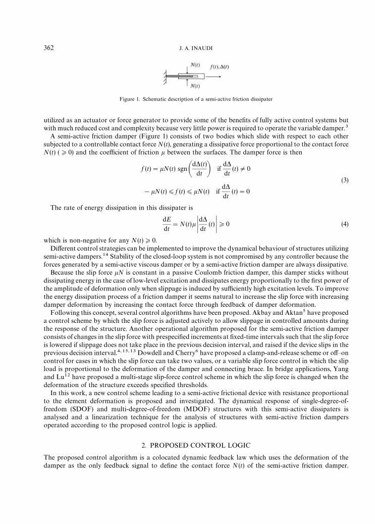
Figure 1. Schematic description of a semi-active friction dissipater
utilized as an actuator or force generator to provide some of the benefits of fully active control systems butwith much reduced cost and complexity because very little power is required to operate the variable damper.3
A semi-active friction damper (Figure 1) consists of two bodies which slide with respect to each othersubjected to a controllable contact force N(t), generating a dissipative force proportional to the contact forceN(t) (*0) and the coefficient of friction k between the surfaces. The damper force is then
f (t)"kN(t) sgnAd*(t)
dt B ifd*dt
(t)O0
(3)
!kN (t))f (t))kN(t) ifd*dt
(t)"0
The rate of energy dissipation in this dissipater is
dE
dt"N(t)k K
d*dt
(t) K*0 (4)
which is non-negative for any N (t)*0.Different control strategies can be implemented to improve the dynamical behaviour of structures utilizing
semi-active dampers.14 Stability of the closed-loop system is not compromised by any controller because theforces generated by a semi-active viscous damper or by a semi-active friction damper are always dissipative.
Because the slip force kN is constant in a passive Coulomb friction damper, this damper sticks withoutdissipating energy in the case of low-level excitation and dissipates energy proportionally to the first power ofthe amplitude of deformation only when slippage is induced by sufficiently high excitation levels. To improvethe energy dissipation process of a friction damper it seems natural to increase the slip force with increasingdamper deformation by increasing the contact force through feedback of damper deformation.
Following this concept, several control algorithms have been proposed. Akbay and Aktan5 have proposeda control scheme by which the slip force is adjusted actively to allow slippage in controlled amounts duringthe response of the structure. Another operational algorithm proposed for the semi-active friction damperconsists of changes in the slip force with prespecified increments at fixed-time intervals such that the slip forceis lowered if slippage does not take place in the previous decision interval, and raised if the device slips in theprevious decision interval.4,15,13 Dowdell and Cherry6 have proposed a clamp-and-release scheme or off—oncontrol for cases in which the slip force can take two values, or a variable slip force control in which the slipload is proportional to the deformation of the damper and connecting brace. In bridge applications, Yangand Lu12 have proposed a multi-stage slip-force control scheme in which the slip force is changed when thedeformation of the structure exceeds specified thresholds.
In this work, a new control scheme leading to a semi-active frictional device with resistance proportionalto the element deformation is proposed and investigated. The dynamical response of single-degree-of-freedom (SDOF) and multi-degree-of-freedom (MDOF) structures with this semi-active dissipaters isanalysed and a linearization technique for the analysis of structures with semi-active friction dampersoperated according to the proposed control logic is applied.
2. PROPOSED CONTROL LOGIC
The proposed control algorithm is a colocated dynamic feedback law which uses the deformation of thedamper as the only feedback signal to define the contact force N(t) of the semi-active friction damper.
362 J. A. INAUDI

Figure 2. Prior-local-peak operator P[*(t)] (thick line) for arbitrary deformation signal *(t) (thin line)
Mathematically, the controller is expressed as
N(t)"g DP[*(t)]D (5)
where g is the positive gain coefficient with units of stiffness and P[*(t)] the operator defined as follows:
P[*(t)]"*(t!s) where s"Gminx*0:d*dt
(t!x)"0H (6)
and such that * (t!s) is a local peak of the deformation signal.Because the output of P[*(t)] is equal to the value of the input signal at the prior closest local peak,
P[*(t)] is referred to as prior-local-peak operator herein.In equation (5), DP[*(t)] D makes the contact force N (t) proportional to the deformation signal. However,
the controller has memory because the past of the deformation signal is required to determine the controlsignal N(t) at current time t. The absolute value in this expression ensures a non-negative value for thecontact force.
The output of the prior-local-peak operator is illustrated in Figure 2 for an arbitrary deformation signal;*(t) is shown in thin line and P[*(t)] is the piecewise constant signal shown in thick line in the figure. It is notdifficult to prove that the prior-local-peak operator satisfies the property of homogeneity of degree one(HD1), i.e. P[b*(t)]"bP[*(t)] for any b3R.
When operated with the proposed control law (equation (5)), the force in the semi-active damper is givenby
f [*(t)]"gkDP[*(t)] Dsgn Ad*(t)
dt B ifd*dt
(t)O0(7)
!gkDP[*(t)] D)f [*(t)])gkDP[*(t)] D ifd*dt
(t)"0
We call this closed-loop system: modulated homogeneous friction (MHF). Figure 3 shows the hysteresisloops of a MHF dissipater for the deformation signal shown in Figure 2. Rectangular hysteresis loops withvariable slip force can be observed in Figure 3 where the force of the MHF dissipater has been normalized asf [*(t)]/(gk).
MODULATED HOMOGENEOUS FRICTION 363
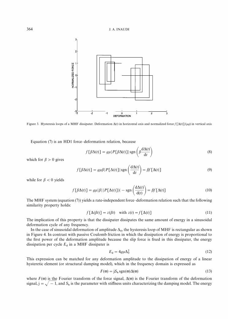
Figure 3. Hysteresis loops of a MHF dissipater. Deformation *(t) in horizontal axis and normalized force f [*(t)]/(kg) in vertical axis
Equation (7) is an HD1 force—deformation relation, because
f [b*(t)]"gkDP[b*(t)] D sgn Abd*(t)
dt B (8)
which for b'0 gives
f [b* (t)]"gkbDP[* (t)] D sgn Ad*(t)
dt B"bf [*(t)] (9)
while for b(0 yields
f [b*(t)]"gkDbD DP[* (t)] D (!sgn Ad*(t)
d(t) B"bf [*(t)] (10)
The MHF system (equation (7)) yields a rate-independent force—deformation relation such that the followingsimilarity property holds:
f [*(bt)]"z (bt) with z(t)"f [*(t)] (11)
The implication of this property is that the dissipater dissipates the same amount of energy in a sinusoidaldeformation cycle of any frequency.
In the case of sinusoidal deformation of amplitude *0, the hysteresis loop of MHF is rectangular as shown
in Figure 4. In contrast with passive Coulomb friction in which the dissipation of energy is proportional tothe first power of the deformation amplitude because the slip force is fixed in this dissipater, the energydissipation per cycle E
$in a MHF dissipater is
E$"4gk*2
0(12)
This expression can be matched for any deformation amplitude to the dissipation of energy of a linearhysteretic element (or structural damping model), which in the frequency domain is expressed as
F (-)"jS)sgn(-)*(-) (13)
where F (-) is the Fourier transform of the force signal, *(-) is the Fourier transform of the deformationsignal, j"J!1, and S
)is the parameter with stiffness units characterizing the damping model. The energy
364 J. A. INAUDI
Figure 4. Hysteresis loop of a MHF dissipater subjected to sinusoidal deformation (thick line) and hysteresis loop of an equivalentlinear hysteretic element (thin line)
dissipation in a cycle of harmonic deformation of this linear model is
E$"nS
)*2
0(14)
Therefore, both models dissipate the same amount of energy in a sinusoidal deformation cycle if
S)"
4gkn
(15)
It can be proven that the linear model in equation (13) with S)satisfying equation (15) is the equivalent linear
element for MHF (equation (7)) resulting from the use of the harmonic linearization technique.14 In thismethod, an equivalent linear model is sought by minimizing the square of the difference between the force ofthe non-linear model and that of the equivalent linear model over a cycle of sinusoidal deformation.
Figure 4 shows the hysteresis loops of the MHF element (in thick line) and that of an equivalent linearhysteretic element (thin line) corresponding to a cycle of sinusoidal deformation *(t)"*
0sin-t. The
normalized forces f (t)/S)
of both MHF and linear hysteretic damping are plotted as functions of thenormalized deformation *(t)/*
0. The constant S
)satisfies equation (15); therefore, both hysteresis loops in
this figure enclose the same area for any deformation amplitude. The model in equation (13) with S)satisfying
equation (15) can be utilized as an equivalent linear element for MHF; this linearization will be used later toestimate the response of SDOF and MDOF structures with MHF.
The proposed control logic that makes the prior-local-peak operator yields a more efficient dissipater thana control logic that makes the contact force simply proportional to the current deformation signal. Assumethe following memoryless feedback law is utilized for the semi-active friction damper
N (t)"eD*(t) D (16)
where e is the constant feedback gain with units of stiffness. This control scheme leads also to a homogeneousforce—deformation relation because from equations (3) and (16)
f A*(t),d*(t)
dt B"ekD*(t) D sgnAd*(t)
dt B"ek*(t) sgnA*(t)d*(t)
dt B (17)
MODULATED HOMOGENEOUS FRICTION 365
which is an HD1 variable-stiffness element referred to as Reid’s model of hysteretic damping.16,17 This modelyields triangular hysteresis loops enclosing only half the area enclosed by the rectangular hysteresis of theproposed closed-loop system for the same value of maximum force, making this control scheme (equation(16)) less efficient than MHF (equation (5)).
3. SDOF STRUCTURAL MODELS INCORPORATING MHF DISSIPATERS
3.1. Free vibration of SDOF structures with MHFConsider the following model of a SDOF structure with a semi-active friction damper operated according
to the proposed control law (equation (7)):
md2y
dt2(t)#u2my(t)#gkDP[y(t)] Dsgn A
dy
dt(t)B"0 (18)
where m is the mass of the oscillator, u the undamped natural frequency and y (t) the displacement. Since eachterm in this differential equation is HD1, the oscillator is HD1.14 The free vibration response for initialconditions y (0)"½
nand dy/dt (0)"0 is periodic with a decay ratio independent of the amplitude of
vibration as we demonstrate in the following.For an oscillatory response, it is required that
a"gk
u2m(
1
2(19)
It can be demonstrated that for a*12, the displacement y (t) does not exhibit an oscillatory response in the
absence of external loading.During the first half cycle, P[y(t)]"y(0)"½
nand the solution of equation (18) can be obtained as
y (t)"a½n#½
n(1!a) cosut, 0)t)n/u (20)
At t"n/u, the displacement reaches a local peak
yAnuB"(2a!1) ½
n(21)
For n/u(t)2n/u, P[y(t)]"(2a!1)½nand the solution can be obtained in a similar fashion. After one
cycle,
y A2nuB"½
n`1"(1!2a)2½
n(22)
Therefore, the period of oscillation and decay ratio are
¹"
2nu
(23)
c"½
n`1½
n
"(1!2a)2 (24)
This means that provided a(12, the period of vibration of this non-linear system is unchanged by the
feedback gain g of the semi-active friction dissipater while the decay ratio is highly dependent on g (seeequations (24) and (19)).
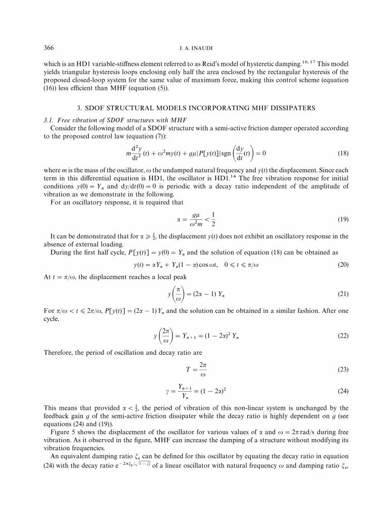
Figure 5 shows the displacement of the oscillator for various values of a and u"2n rad/s during freevibration. As it observed in the figure, MHF can increase the damping of a structure without modifying itsvibration frequencies.
An equivalent damping ratio m%can be defined for this oscillator by equating the decay ratio in equation
(24) with the decay ratio e~2nm% @J1!m2% of a linear oscillator with natural frequency u and damping ratio m
%,
366 J. A. INAUDI
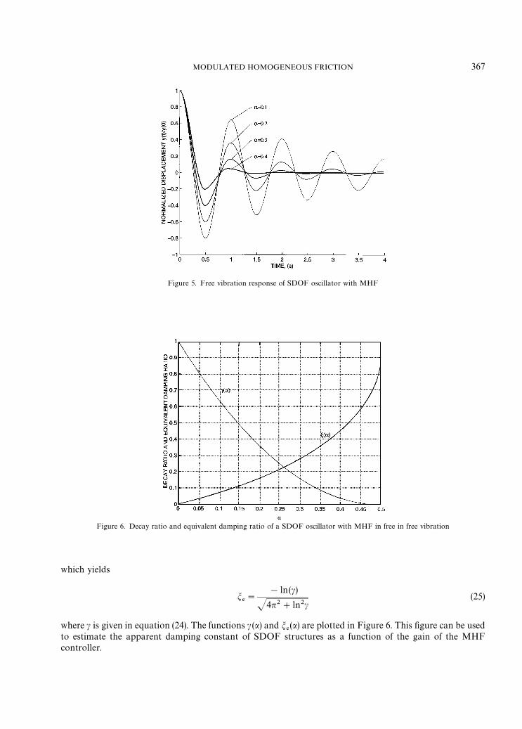
Figure 5. Free vibration response of SDOF oscillator with MHF
Figure 6. Decay ratio and equivalent damping ratio of a SDOF oscillator with MHF in free in free vibration
which yields
m%"
!ln(c)
J4n2#ln2c(25)
where c is given in equation (24). The functions c (a) and m%(a) are plotted in Figure 6. This figure can be used
to estimate the apparent damping constant of SDOF structures as a function of the gain of the MHFcontroller.
MODULATED HOMOGENEOUS FRICTION 367

3.2. Response to harmonic excitation
Let us compute the steady-state response of the SDOF oscillator with MHF subjected to sinusoidalexcitation. The equation of motion to be solved is
d2y
dt2(t)#u2y(t)"!au2 DP[y (t)] D sgnA
dy
dt(t)B#¼ sin(-t#u) (26a)
y(!R)"0,dy (!R)
dt"0 (26b)
where ¼ is the amplitude of the excitation signal (acceleration units), - the forcing frequency and u theunknown phase included so that at steady-state response,
y (0)"½ anddy
dt(0)"0 (27)
where ½ is the amplitude of the displacement response at steady state. ½ and u are unknown and can becomputed as follows.
For the first half cycle of the steady-state response, P[y(t)]"½ and for -Ou,
y (t)"a½#
¼
u2!-2sin(-t#u)#B sinut#C cosut, 0)t)n/- (28)
where the constants of integration B and C are
B"!
¼-
u(u2!-2)cosu, C"½(1!a)!
¼
u2!-2sinu (29)
At t"n/-,
y An-B"!½ and
dy
dt An-B"0 (30)
Therefore, from equations (28) and (30), we obtain two non-linear equations in ½ and u whose solution givesus the steady-state response of the oscillator. These are
½(1#a)#¼
u2!-2sin(n#u)#B sinA
un- B#C cos A
un- B"0 (31a)
¼-
u2!-2cos(n#u)#Bu cosA
un- B!Cu sinA
un- B"0 (31b)
Figure 7 shows with ‘o’ symbols the normalized amplitude D½u2/¼ D of this oscillator subjected toa sinusoidal excitation signal as a function of the forcing frequency - for various values of a and u"2n rad/s.The figure also shows (in solid line) the amplitude of the response of the equivalent linear oscillator which inthe frequency domain satisfies
[!-2#u2#jSh
msgn(-)]½(-)"¼(-) (32)
where ½(-) is the Fourier transform of y(t) , ¼(-) the Fourier transform of the excitation, and S)
is theparameter of the equivalent linear model given in equation (15). From equations (15), (19) and (32), we obtain
K½u2
¼ K"u2
J(u2!-2)2#((4au2/n) sgn(-))2(33)
which gives the normalized steady-state amplitude of the equivalent linear hysteretic oscillator. This functionis plotted in solid line in Figure 7 which shows very good accuracy of the linearization method.
To analyse the vibration reduction achievable with MHF, the response of a SDOF oscillator withundamped period of vibration ¹"1s and various values of a subjected to the El Centro ground-acceleration
368 J. A. INAUDI
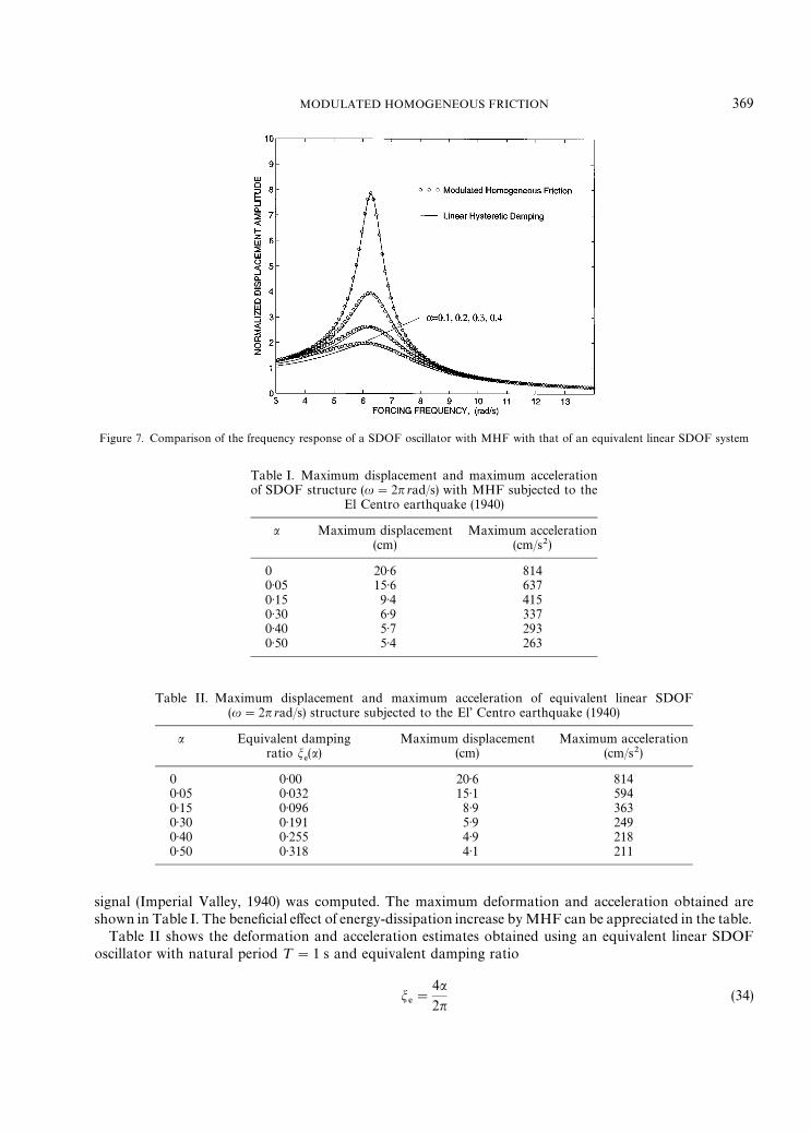
Figure 7. Comparison of the frequency response of a SDOF oscillator with MHF with that of an equivalent linear SDOF system
Table I. Maximum displacement and maximum accelerationof SDOF structure (u"2n rad/s) with MHF subjected to the
El Centro earthquake (1940)
a Maximum displacement Maximum acceleration(cm) (cm/s2)
0 20·6 8140·05 15·6 6370·15 9·4 4150·30 6·9 3370·40 5·7 2930·50 5·4 263
Table II. Maximum displacement and maximum acceleration of equivalent linear SDOF(u"2n rad/s) structure subjected to the El’ Centro earthquake (1940)
a Equivalent damping Maximum displacement Maximum accelerationratio m
%(a) (cm) (cm/s2)
0 0·00 20·6 8140·05 0·032 15·1 5940·15 0·096 8·9 3630·30 0·191 5·9 2490·40 0·255 4·9 2180·50 0·318 4·1 211
signal (Imperial Valley, 1940) was computed. The maximum deformation and acceleration obtained areshown in Table I. The beneficial effect of energy-dissipation increase by MHF can be appreciated in the table.
Table II shows the deformation and acceleration estimates obtained using an equivalent linear SDOFoscillator with natural period ¹"1 s and equivalent damping ratio
m%"
4a2n
(34)
MODULATED HOMOGENEOUS FRICTION 369
which is obtained applying the modal strain energy method to this oscillator.18 Comparing Tables I and II, itcan be observed that the accuracy of this linearization technique worsens as a increases.
4. MDOF STRUCTURAL MODELS INCORPORATING MHF DISSIPATERS
4.1. Modes of vibration
A structural system with semi-active friction dampers can show modes of vibration during free vibration ifcertain conditions are satisfied. This characteristic is shared by a number of HD1 dynamical systems.14
Consider the following model of an N-DOF structure:
Md2y
dt2(t)#Ky(t)#
N%+i/1
¸Tifi[*
i(t)]"0 (35)
where M is the mass matrix, K the stiffness matrix, y (t) the displacement vector, Nethe number of friction
dissipaters, ¸ithe transformation from structure displacements to the deformation of the ith friction damper
*i(t)"¸
iy (t) (36)
and fi[*
i(t)] is the force in the ith MHF dissipater:
fi[*
i(t)]"kg
iDP[¸
iy (t)] Dsgn A¸i
dy
dt(t)B (37)
We have assumed the same coefficient of friction k for all dissipaters, and a feedback gain gifor the ith
dissipater. It is worth emphasizing that each dissipater is operated by an independent controller using thedeformation of each dissipater as feedback signal.
Let the response be parallel to a mode of vibration /lof the undamped structure,
y (t)"/lql(t) (38)
where ql(t) is the modal co-ordinate. If equation (38) is satisfied,
fi(t)"kg
iD¸
i/
lDDP[q
l(t)] Dsgn(¸
i/l) sgn A
dql
dt(t)B"kg
i¸
i/
lDP[q
l(t)] DsgnA
dql
dt(t)B (39)
If we define
D"kN%+i/1
¸Tigi¸i
(40)
from equations (35) and (38) we can write
M/l
d2ql
dt2(t)#K/
lql(t)#D/
lP[q
l(t)] sgnA
dql
dt(t)B"0 (41)
If D is classical, the vectors M/l, K/
land D/
lare parallel for all /
l, l"1, 2, 2, N and the system can show
modes of vibration if the initial condition is parallel to a particular mode shape. Furthermore, the modalco-ordinate satisfies in this case
d2ql
dt2(t)#u2
lq(t)#a
lu2
lP[q
l(t)] sgnA
dql
dt(t)B"0 (42)
where
u2lM/
l"K/
l, a
l"
/TlD/
lu2
l/TlM/
l
(43)
370 J. A. INAUDI
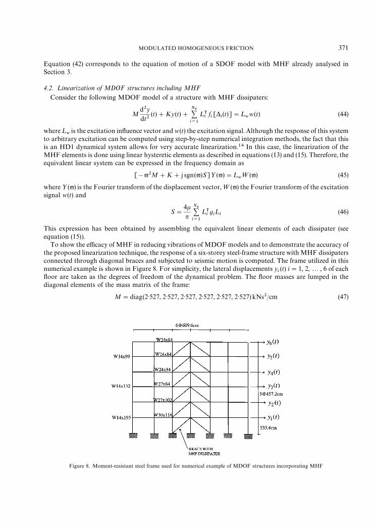
Figure 8. Moment-resistant steel frame used for numerical example of MDOF structures incorporating MHF
Equation (42) corresponds to the equation of motion of a SDOF model with MHF already analysed inSection 3.
4.2. ¸inearization of MDOF structures including MHF
Consider the following MDOF model of a structure with MHF dissipaters:
Md2y
dt2(t)#Ky(t)#
N%+i/1
¸Ti
fi[*
i(t)]"¸
ww(t) (44)
where¸w
is the excitation influence vector and w (t) the excitation signal. Although the response of this systemto arbitrary excitation can be computed using step-by-step numerical integration methods, the fact that thisis an HD1 dynamical system allows for very accurate linearization.14 In this case, the linearization of theMHF elements is done using linear hysteretic elements as described in equations (13) and (15). Therefore, theequivalent linear system can be expressed in the frequency domain as
[!-2M#K#j sgn(-)S]½(-)"¸w¼(-) (45)
where ½(-) is the Fourier transform of the displacement vector, ¼(-) the Fourier transform of the excitationsignal w(t) and
S"4kn
N%+i/1
¸Tigi¸i
(46)
This expression has been obtained by assembling the equivalent linear elements of each dissipater (seeequation (15)).
To show the efficacy of MHF in reducing vibrations of MDOF models and to demonstrate the accuracy ofthe proposed linearization technique, the response of a six-storey steel-frame structure with MHF dissipatersconnected through diagonal braces and subjected to seismic motion is computed. The frame utilized in thisnumerical example is shown in Figure 8. For simplicity, the lateral displacements y
i(t) i"1, 2,2, 6 of each
floor are taken as the degrees of freedom of the dynamical problem. The floor masses are lumped in thediagonal elements of the mass matrix of the frame:
M"diag(2·527, 2·527, 2·527, 2·527, 2·527, 2·527) kNs2/cm (47)
MODULATED HOMOGENEOUS FRICTION 371
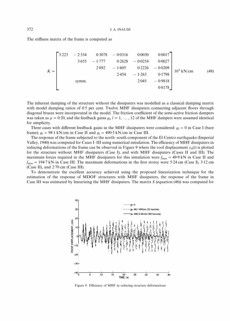
Figure 9. Efficiency of MHF in reducing structure deformations
The stiffness matrix of the frame is computed as
K"C3·223 !2·334 0·3078 !0·0316 0·0030 0·0017
3·655 !1·777 0·2628 !0·0254 0·0027
2·892 !1·605 0·2226 !0·0209
2·454 !1·263 0·1798
symm. 2·045 !0·9818
0·8178D 103 kN/cm (48)
The inherent damping of the structure without the dissipaters was modelled as a classical damping matrixwith model damping ratios of 0·5 per cent. Twelve MHF dissipaters connecting adjacent floors throughdiagonal braces were incorporated in the model. The friction coefficient of the semi-active friction damperswas taken as k"0·20, and the feedback gains g
l, l"1, 2 , 12 of the MHF dampers were assumed identical
for simplicity.Three cases with different feedback gains in the MHF dissipaters were considered: g
l"0 in Case I (bare
frame); gl"98·1 kN/cm in Case II and g
l"490·5 kN/cm in Case III.
The response of the frame subjected to the north—south component of the El Centro earthquake (ImperialValley, 1940) was computed for Cases I—III using numerical simulation. The efficiency of MHF dissipaters inreducing deformations of the frame can be observed in Figure 9 where the roof displacement y
6(t) is plotted
for the structure without MHF dissipaters (Case I), and with MHF dissipaters (Cases II and III). Themaximum forces required in the MHF dissipaters for this simulation were f
.!9"49·9 kN in Case II and
f.!9
"194·7 kN in Case III. The maximum deformations in the first storey were 5·24 cm (Case I), 3·12 cm(Case II), and 2·70 cm (Case III).
To demonstrate the excellent accuracy achieved using the proposed linearization technique for theestimation of the response of MDOF structures with MHF dissipaters, the response of the frame inCase III was estimated by linearizing the MHF dissipaters. The matrix S (equation (46)) was computed for
372 J. A. INAUDI
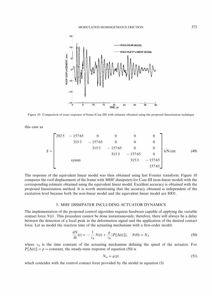
Figure 10. Comparison of exact response of frame (Case III) with estimate obtained using the proposed linearization technique
this case as
S"C292·5 !157·65 0 0 0 0
315·3 !157·65 0 0 0
315·3 !157·65 0 0
315·3 !157·65 0
symm 315·3 !157·65
157·65D kN/cm (49)
The response of the equivalent linear model was then obtained using fast Fourier transform. Figure 10compares the roof displacement of the frame with MHF dissipaters for Case III (non-linear model) with thecorresponding estimate obtained using the equivalent linear model. Excellent accuracy is obtained with theproposed linearization method. It is worth mentioning that the accuracy obtained is independent of theexcitation level because both the non-linear model and the equivalent linear model are HD1.
5. MHF DISSIPATER INCLUDING ACTUATOR DYNAMICS
The implementation of the proposed control algorithm requires hardware capable of applying the variablecontact force N(t) . This procedure cannot be done instantaneously; therefore, there will always be a delaybetween the detection of a local peak in the deformation signal and the application of the desired contactforce. Let us model the reaction time of the actuating mechanism with a first-order model:
dN
dt(t)"!
1
qN
N (t)#g
qN
DP[*(t)] D, N (0)"N0
(50)
where qN
is the time constant of the actuating mechanism defining the speed of the actuator. ForP[* (t)]"p"constant, the steady-state response of equation (50) is
N44"g Dp D (51)
which coincides with the control contact force provided by the model in equation (5).
MODULATED HOMOGENEOUS FRICTION 373
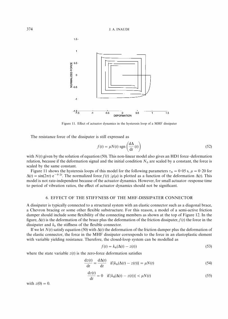
Figure 11. Effect of actuator dynamics in the hysteresis loop of a MHF dissipater
The resistance force of the dissipater is still expressed as
f (t)"kN(t) sgn Ad*dt
(t)B (52)
with N (t) given by the solution of equation (50). This non-linear model also gives an HD1 force—deformationrelation, because if the deformation signal and the initial condition N
0are scaled by a constant, the force is
scaled by the same constant.Figure 11 shows the hysteresis loops of this model for the following parameters q
N"0·05 s, k"0·20 for
*(t)"sin(2nt) e~0>2t. The normalized force f (t) /g(k) is plotted as a function of the deformation *(t). Thismodel is not rate-independent because of the actuator dynamics. However, for small actuator—response timeto period of vibration ratios, the effect of actuator dynamics should not be significant.
6. EFFECT OF THE STIFFNESS OF THE MHF-DISSIPATER CONNECTOR
A dissipater is typically connected to a structural system with an elastic connector such as a diagonal brace,a Chevron bracing or some other flexible substructure. For this reason, a model of a semi-active frictiondamper should include some flexibility of the connecting members as shown at the top of Figure 12. In thefigure, *(t) is the deformation of the brace plus the deformation of the friction dissipater, f (t) the force in thedissipater and k
bthe stiffness of the flexible connector.
If we let N (t) satisfy equation (50) with *(t) the deformation of the friction damper plus the deformation ofthe elastic connector, the force in the MHF dissipater corresponds to the force in an elastoplastic elementwith variable yielding resistance. Therefore, the closed-loop system can be modelled as
f (t)"k"(*(t)!z(t) ) (53)
where the state variable z (t) is the zero-force deformation satisfies
dz (t)
dt"
d*(t)
dtif Dk
"(* (t)!z(t) )D"kN(t) (54)
dz(t)
dt"0 if Dk
"(*(t)!z (t) ) D(kN (t) (55)
with z(0)"0.
374 J. A. INAUDI

Figure 12. Schematic diagram of MHF dissipater with elastic connector and effect of connector flexibility and actuator dynamics on thehysteresis loop of the dissipater
It is not difficult to prove that if N (t) is given by equation (50), the force—deformation relation of thesemi-active dissipater including connector flexibility (equations (50) and (53)) is HD1.
Figure 12 shows the hysteresis loops of a model of MHF dissipater including both actuator dynamics andflexibility of the connector. The parameters selected for the simulation were k
"/g"1, k"0·10, and
qN"0·05 s. The deformation signal is *(t)"sin(2nt) e~0>2t. The figure shows the normalized force f (t) /(kg)
as a function of the deformation. The effects of both elasticity of the connector and actuator dynamics can beincorporated in this model providing a very powerful tool for the prediction of the response of structures withMHF dissipaters.
7. CONCLUDING COMMENTS
A new control algorithm for semi-active friction dissipaters has been proposed. The system is referred to asModulated Homogeneous Friction (MHF). When operated with the proposed control logic, this semi-activefriction dissipater shows a homogeneous-of-degree-one force—deformation relation. This non-linear consti-tutive relation shows very promising features such as quadratic dissipation of energy per cycle in thedeformation amplitude, maximum dissipation efficiency for resistance-force level proportional to deforma-tion, and simple and accurate linearization.
Some of the characteristics of structures incorporating this type of dissipater have been analysed includingthe free vibration response of SDOF structures, harmonic response of SDOF structures, and the existence ofmodes of vibration in the case of MDOF systems. The use of equivalent linear hysteretic elements toapproximate the response of MDOF structures incorporating MHF dissipaters have proven very accurate.
A comparison of the performance of structures with this type of dissipater and structures with passiveviscoelastic and frictional dissipaters should be conducted to assess the merits of this semi-active device.Experimental research should be conducted to verify the feasibility of the proposed semi-active device. Thisresearch should also confirm the need or not of further modelling techniques for the semi-active dissipaterincluding aspects such as elasticity of the connectors, delays and dynamics of the actuator applying thedesired contact force. The design of filters for the detection of local peaks in the deformation signal in thepresence of noisy signals output by the sensors is another topic that requires investigation and experimentalverification.
MODULATED HOMOGENEOUS FRICTION 375
ACKNOWLEDGEMENTS
This research was conducted with the financial support of the National Science Foundation under Grant No.BCS 9302101 and of the National Center for Earthquake Engineering Research of the University of NewYork at Buffalo. This support is greatly appreciated. The author thanks the reviewers for their valuablecomments.
REFERENCES
1. A. A. Ferri and B. S. Heck, ‘Semi-active suspension using dry friction energy dissipation’, Proc. 1992 American control conf., Vol. 1,1992, pp. 31—35.
2. D. Karnopp, M. J. Crosby and R. A. Harwood, ‘Vibration control using semi-active force generators’, J. eng. ind. trans. ASME 96,619—626 (1974).
3. D. Karnopp, ‘Design principles for vibration control systems using semi-active dampers’, J. dyn. systems measurement control trans.ASME 112, 448—455 (1990).
4. Z. Akbay and H. K. Aktan, ‘Actively regulated friction slip braces’, Proc. 6th Canadian conf. on earthquake engineering, University ofToronto Press, Toronto, 1991.
5. Z. Akbay and H. M. Aktan, ‘Intelligent energy dissipation devices’, Proc. 4th º.S. national conf. on earthquake engineering, PalmSprings, Vol. 3, Earthquake Engineering Research Institute, 1990, pp. 427—435.
6. D. J. Dowdell and S. Cherry, ‘Semi-active friction dampers for seismic response control of structures’, Proc. 5th º.S. national conf. onearthquake engineering, Vol. I, Earthquake Engineering Research Institute, California, 1994, pp. 819—828.
7. T. Fujita, M. Shimazaki, Y. Hayamizu, S. Aizawa, M. Higashino and N. Haniuda, ‘Semiactive seismic isolation using controllablefriction damper’, Bull. earthquake resistant structure research center (27) 21—31 (1994).
8. J. C. Hayen and W. D. Iwan, ‘Response control of structural systems using active interface damping’, in G. W. Housner, S. F. Masriand A. G. Chassiakos (eds), Proc. 1st world conf. on structural control, Vol. 1, University of Southern California, Los Angeles, 1994,pp. WA2/23—32.
9. K. Kawashima, S. Unjoh and H. Mukai, ‘Seismic response control of highway bridges by variable damper’, Proc. 5th º.S. nationalconf. on earthquake engineering, Vol. I, Earthquake Engineering Research Institute, California, 1994, pp. 829—838.
10. S. Kawamura, M. Shinozuka, S. Fujii and Q. Feng, ‘Hybrid isolation system using friction-controllable sliding bearings’, in Y. K.Wen (ed.), Proc. int. workshop on intelligent systems, intelligent structures, Vol. 2, monitoring and control, Elsevier Applied Science,London and New York, 1992.
11. S. Nagarajaiah, M. Q. Feng and M. Shinozuka, ‘Control of structures with friction controllable sliding isolation bearings’, Soil dyn.earthquake eng. 12 103—112 (1993).
12. C. Yang and L. W. Lu, ‘Seismic response control of cable-stayed bridges by semi-active friction damping’, Proc. º.S. national conf. onearthquake engineering, Chicago, Vol. I, Earthquake Engineering Research Insitute, 1994, pp. 911—920.
13. Z. Akbay and H. M. Aktan, ‘Abating earthquake effects on buildings by active slip brace devices’, Shock vibr. 2, 133—142 (1995).14. J. A. Inaudi and J. M. Kelly, ‘Nonlinear homogeneous dynamical systems’, Report No. ºCB/EERC-93/11, Earthquake Engineering
Research, University of California at Berkeley, 1995.15. S. Kannan, H. M. Uras and H. M. Aktan, ‘Active control of building seismic response by energy dissipation’, Earthquake eng. struct.
dyn. 24, 747—759 (1995).16. T. K. Caughey and Vijayaraghavan, ‘Free and forced oscillations of a dynamic system with linear hysteretic damping (nonlinear
theory) ’, Int. j. non-linear mech. 5, 533—555 (1970).17. J. A. Inaudi, D. K. Nims and J. M. Kelly, ‘On the analysis of structures with energy dissipating restraints’, Report No.
ºCB/EERC-93/13, Earthquake Engineering Research, University of California at Berkeley, 1993.18. J. A. Inaudi, A. Zambrano and J. M. Kelly, ‘On the analysis of structures with viscoelastic dampers’, Report No. ºCB/EERC-93/06,
Earthquake Engineering Research, University of California at Berkeley, 1993.19. S. Cherry, ‘Research on friction damping at the University of British Columbia’, in Masri and Housner (eds) Proc. int. workshop on
structural control, USC Publication No. CE-9311, University of Southern California, 1993, pp. 84—91.20. M. Q. Feng, M. Shinozuka and S. Fujii, ‘Friction-controllable sliding isolation system’, J. eng. mech. ASCE 119, 1845—1864 (1993).21. J. A. Inaudi and J. Hayen, ‘Research on variable-structure control in the United States’, Proc. post-smirt seminar on seismic isolation,
passive energy dissipation and control of vibrations of structures, University of Chile, Santiago, Chile, 1995.22. J. A. Inaudi and J. M. Kelly, ‘Dynamics of homogeneous frictional systems’, in Vol I., A. Guran, F. Pfeiffer and K. Popp (eds.),
Dynamics with Friction: Modelling, Analysis and Experiments, World Scientific, Singapore, 1995.23. Z. Liang, M. Tong and G. C. Lee, ‘Real-time structural parameter modification (RSPM): development of innervated structures’,
¹echnical Report NCEER-95-0012, National Center for Earthquake Engineering Research, Unviersity of New York at Buffalo,1995.
24. W. H. Patten, Q. He, C. C. Kuo, L. Liu and R. L. Sack, ‘Suppression of vehicle induced bridge vibration via semi-active hydraulicdampers (SAVD), in G. W. Housner, S. F. Masri and A. G. Chassiakos (eds.), Proc. 1st world conf. on structural control, Vol. 3,University of Southern California, Los Angeles, 1994, pp. FA1/30—38.
.
376 J. A. INAUDI