Modularity Approach of the Modular Pebble Bed Reactor (MPBR)
34
4/23/03 MIT NED MPBR Modularity Approach of the Modular Pebble Bed Reactor (MPBR) Marc Berte Professor Andrew Kadak Massachusetts Institute of Technology Nuclear Engineering Department Nuclear Energy Research Initiative Grant Number DE-FG03-00SF22168
Transcript of Modularity Approach of the Modular Pebble Bed Reactor (MPBR)

4/23/03
MIT NEDMPBR
Modularity Approachof the
Modular Pebble Bed Reactor (MPBR)
Marc BerteProfessor Andrew Kadak
Massachusetts Institute of TechnologyNuclear Engineering Department
Nuclear Energy Research InitiativeGrant Number
DE-FG03-00SF22168

4/23/03
MIT NEDMPBR Project Objectives
• To apply modularity principles to the design, construction and operation of advanced nuclear energy plants
• To employ manufacturing and factory assembly principles to nuclear plants.
• To minimize on site work by assembling plants on site rather than construct them as in the past.
• To allow for conventional truck and rail shipments of most components allowing for siting flexibility.
• To reduce overall construction time and cost.

4/23/03
MIT NEDMPBRModular High Temperature Pebble Bed Reactor
• Modules added to meet demand.
• No Reprocessing• High Burnup >90,000
Mwd/MT• Direct Disposal of HLW• Process Heat
Applications -Hydrogen, water
• 120 MWe• Helium Cooled• 8 % Enriched Fuel• Built in 2 Years• Factory Built• Site Assembled• On--line Refueling

4/23/03
MIT NEDMPBR Reference Plant
Modular Pebble Bed Reactor
Thermal Power 250 MWCore Height 10.0 mCore Diameter 3.5 mFuel UO2Number of Fuel Pebbles 360,000Microspheres/Fuel Pebble 11,000Fuel Pebble Diameter 60 mmMicrosphere Diameter ~ 1mmCoolant Helium

4/23/03
MIT NEDMPBR
Indirect Cycle with Intermediate Helium to Helium Heat Exchanger
Current Design Schematic
Generator
522.5°C7.89MPa125.4kg/s
509.2°C7.59MPa 350°C
7.90MPa
Reactorcore
900°C
7.73MPa
800°C
7.75MPa
511.0°C2.75MPa
96.1°C2.73MPa
69.7°C8.0MPa
326°C105.7kg/s
115 °C1.3kg/s
69.7°C
1.3kg/s
280 °C520°C126.7kg/s
Circulator
HPT52.8MW
Precooler
Inventorycontrol
BypassValve
Intercooler
IHX
Recuperator
Cooling RPV
LPT52.8MW
PT136.9MW
799.2 C6.44 MPa
719.°C5.21MPa
MPC226.1 MW
MPC126.1MW
LPC26.1 MW
HPC26.1MW
30 C2.71MPa
69.7 C4.67MPa

4/23/03
MIT NEDMPBR Features of Current Design
Three-shaft ArrangementPower conversion unit
2.96Cycle pressure ratio
900°C/520°CCore Outlet/Inlet T
126.7 kg/sHelium Mass flowrate
48.1% (Not take into account cooling IHX and HPT. if considering, it is believed > 45%)
Plant Net Efficiency
120.3 MWNet Electrical Power
132.5 MWGross Electrical Power
250 MWThermal Power

4/23/03
MIT NEDMPBR 1150 MW Combined Heat and Power Station
Turbine Hall Boundary
Admin
Training
ControlBldg.
MaintenanceParts / Tools
10
9
8
7
6 4 2
5 3 1
0 20 40 60 80 100 120 140 160
0
20
40
60
80
100
Primary island withreactor and IHX
Turbomachinery
Ten-Unit VHTR Plant Layout (Top View)(distances in meters)
Equip AccessHatch
Equip AccessHatch
Equip AccessHatch
Oil Refinery
Hydrogen ProductionDesalinization Plant
VHTR Characteristics- Temperatures > 900 C- Indirect Cycle - Core Options Available- Waste Minimization

4/23/03
MIT NEDMPBR Modularity Progression
• Conventional Nuclear Power Systems• Assembled on site• Component-level transportation• Extensive Site Preparation
• Advanced Systems• Mass Produced / “Off the Shelf” Designs• Construction / Assembly Still Primarily on Site
• MPBR• Mass Produced Components• Remote Assembly / Simple Transportation & Construction
This is different than other Generation IV approaches in that modularity is the objective which means smaller units.

4/23/03
MIT NEDMPBR MPBR Modularity Plan
• Road- Truck / Standard-Rail Transportable– 8 x 10 x 60 ft. 100,000 kg Limits
• Bolt-together Assembly– Minimum labor / time on site required– Minimum assembly tools– Goal: Zero Welding
• Minimum Site Preparation– BOP Facilities designed as “Plug-and-Play” Modules– Single Level Foundation– System Enclosure integrated into modules
• ASME Code compliant– Thermal expansion limitations– Code material limitations

4/23/03
MIT NEDMPBR
Design Elements
• Assembly• Self-locating Space-frame Contained Modules and
Piping.• Bolt-together Flanges Join Module to Module• Space-frame Bears Facility Loads, No Additional
Structure
• Transportation / Delivery• Road-mobile Transportation Option
– Reduces Site Requirements (Rail Spur Not Required)
• Module Placement on Site Requires Simple Equipment
• Footprint• Two Layer Module Layout Minimizes Plant Footprint• High Maintenance Modules Placed on Upper Layer

4/23/03
MIT NEDMPBR Top Down View of Pebble Bed Reactor Plant
IHX Module
ReactorVessel
Recuperator Module
Turbogenerator
HP Turbine
MP Turbine
LP Turbine
Power Turbine HP Compressor
MP Compressor
LP Compressor
Intercooler #1
Intercooler #2
Precooler
~77 ft.
~70 ft.
Plant Footprint
TOP VIEWWHOLE PLANT

4/23/03
MIT NEDMPBR
Total Modules Needed For Plant Assembly (21): Nine 8x30 Modules, Five 8x40 Modules, Seven 8x20 Modules
Six 8x30 IHX Modules Six 8x20 Recuperator Modules
8x30 Lower Manifold Module8x30 Upper Manifold Module
8x30 Power Turbine Module
8x40 Piping & Intercooler #1 Module
8x40 HP Turbine, LP Compressor Module
8x40 MP Turbine, MP Compressor Module
8x40 LP Turbine, HP Compressor Module
8x40 Piping and Precooler Module
8x20 Intercooler #2 Module
PLANT MODULE SHIPPING BREAKDOWN

4/23/03
MIT NEDMPBR Concept
• Modular Construction– Space-frame modules
• Stackable• Self-aligning• Pre-constructed off-site
– Minimal Assembly On-Site• Connect Flanges / Fluid Lines /
Utilities• Pre-Assembled Control Facilities
• Distributed Production– Common, Simple Module Design– Minimizes Transportation Req.– Eliminates Manufacturing Capital
Expense– Module Replacement Instead of
Repair—Modules Returned to Fabricator
• Road-mobile Transportation– Reduces Cost—Construction of Rail
Spur / Canal Not Required– Reduces Location Requirements
4/23/03
MIT NEDMPBR
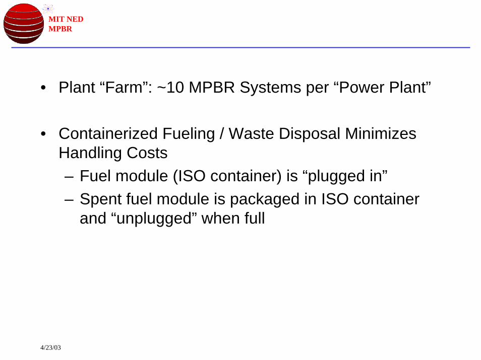
• Plant “Farm”: ~10 MPBR Systems per “Power Plant”
• Containerized Fueling / Waste Disposal Minimizes Handling Costs– Fuel module (ISO container) is “plugged in”– Spent fuel module is packaged in ISO container
and “unplugged” when full

4/23/03
MIT NEDMPBR Example Plant Layout
Secondary (BOP) Side Hall Primary Side Hall
Reactor Vessel
IHX ModulesRecuperator Modules
Turbomachinery
NOTE: Space-frames and ancillary components not shown for clarity
4/23/03
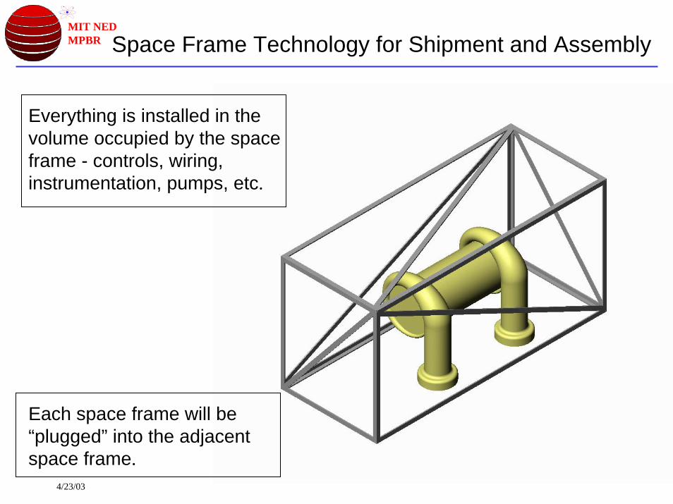
MIT NEDMPBR Space Frame Technology for Shipment and Assembly
Everything is installed in the volume occupied by the space frame - controls, wiring, instrumentation, pumps, etc.
Each space frame will be “plugged” into the adjacent space frame.

4/23/03
MIT NEDMPBR Balance of Plant Components
Compressor Set (Black)
With Axial Intercooler (Tan) High pressure turbine
Precooler
Recuperator ModulePower Turbine
Generator

4/23/03
MIT NEDMPBR Space-Frame Concept
• Standardized Frame Size• 2.4 x 2.6 x 3(n) Meter• Standard Dry Cargo Container• Attempt to Limit Module Mass to
~30t / 6m– ISO Limit for 6m Container– Stacking Load Limit ~190t– ISO Container Mass ~2200kg– Modified Design for Higher
Capacity—~60t / 12m module • Overweight Modules
– Generator (150-200t)– Turbo-Compressor (45t)– Avoid Separating Shafts!– Heavy Lift Handling Required– Dual Module (12m / 60t)
• Stacking Load Limit Acceptable– Dual Module = ~380T
• Turbo-generator Module <300t
• Design Frame for Cantilever Loads– Enables Modules to be Bridged
• Space Frames are the structural supports for the components.
• Only need to build open vault areas for space frame installation - RC & BOP vault
• Alignment Pins on Module Corners– High Accuracy Alignment– Enables Flanges to be Simply
Bolted Together• Standardized Umbilical Locations
– Bus-Layout of Generic Utilities (data/control)

4/23/03
MIT NEDMPBR Thermal and Mechanical Stress Analysis
• CAESAR II Pipe Stress Analysis Code• ASME B31.3 Piping Code• Pipe Material: A335 P2• Spaceframe Material: ASTM A-36• Preliminary Thermal Analysis Performed to
Create Code Compliant Geometry• Hangers not shown for clarity• Preliminary Spaceframe structure
– secondary elements not shown

4/23/03
MIT NEDMPBR Present LayoutReactor Vessel
IHX Vessel
High Pressure Turbine
Low Pressure Turbine
Compressor (4)
Power Turbine
Recuperator Vessel
4/23/03
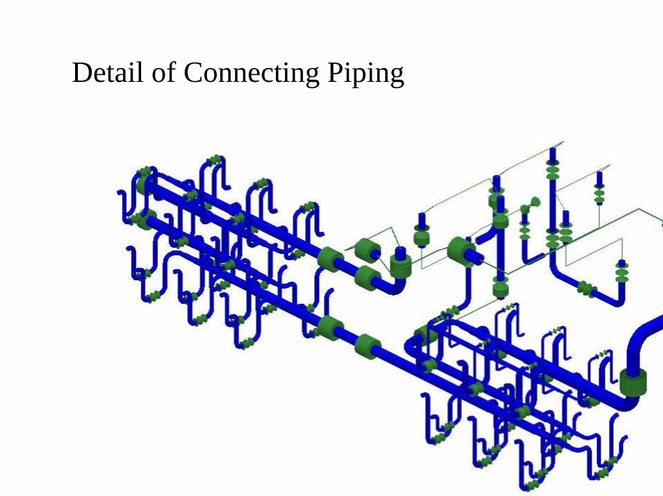
MIT NEDMPBR
Detail of Connecting Piping

4/23/03
MIT NEDMPBR Piping Sizes
0.258Compressor 4 to Recuperator
0.258Intercooler 3 to Compressor 4
0.258Compressor 3 to Intercooler 3
0.2510Intercooler 2 to Compressor 3
0.2510Compressor 2 to Intercooler 2
0.12510Intercooler 1 to Compressor 2
0.12512Compressor 1 to Intercooler 1
0.12513Precooler to Compressor 1
0.12514Recuperator to Precooler
0.2520Power Turbine to Recuperator
0.518Turbine 2 to Power Turbine
0.516Turbine 1 to Turbine 2
0.516IHX to Turbine 1
0.516IHX to Reactor Vessel
0.516Reactor Vessel to IHX
Wall Thickness (in)OD (in)Pipe
Based on 400m/s internal helium flow velocity with metallic liner and internal insulation

4/23/03
MIT NEDMPBR
17.5 m
32 m

4/23/03
MIT NEDMPBR
Overall Structure
25 m
40 m

4/23/03
MIT NEDMPBR 10 Module Plant - 1200 MWe
165 m
110 m

4/23/03
MIT NEDMPBR Views Of Plant Layout
TOP VIEW
SIDE VIEW
FRONT VIEW (FROM REACTOR VESSEL)

4/23/03
MIT NEDMPBR
Plant With Space Frames

4/23/03
MIT NEDMPBR
2.5 m
10 m
Upper IHX Manifold in Spaceframe
3 m

4/23/03
MIT NEDMPBR Distributed Production Concept
“MPBR Inc.”
Space-Frame Specification
Component Fabricator #1
e.g. Turbine Manufacturer
Component Fabricator #N
e.g. Turbine Manufacturer
Component Design
MPBR Construction Site
Site Preparation Contractor
Assembly Contractor
Site and Assembly SpecificationsManagem
ent and Operation
Labor
Component Transportation
Design Information

4/23/03
MIT NEDMPBR
Distributed Production Concept -Virtual Factory !
• Evolution of the “Reactor Factory” Concept• There Is NO Factory
– Off-load Manufacturing Capital Expense to Component Suppliers• Decrease follow-through capital expense by designing to
minimize new tooling—near COTS• Major component fabricators become mid-level integrators—
following design delivered from HQ– Reduces Transportation Costs
• Component weight ≈ Module weight: Why Transport It Twice?– Enables Flexible Capitalization
• Initial systems use components purchased on a one-off / low quantity basis
• Once MPBR demand established, constant production + fabrication learning curve lower costs
4/23/03
MIT NEDMPBR
• Site / Building Design Does Not Require Specialized Expertise– Enables Selection of Construction Contractors By Location /
Cost– Simplified Fabrication Minimizes “MPBR Inc.” Workforce
Required
• Simple Common Space-Frame Design – Can be Easily Manufactured By Each Individual Component
Supplier– Or if necessary sub-contracted to generic structural
fabricator
• Modern CAD/CAE Techniques Enable High First-Fit Probability—Virtual “Test-Fit”

4/23/03
MIT NEDMPBR Current Design Issues
• Thermal Expansion– Piping Must Be Designed for Substantial Thermal
Expansion—requiring Bulky Layout– Flexible Joints Not Possible Due to Code Constraints
• Space-Frame Loads– External (Seismic, etc) – Flexibility Limits– Self-Generated – Internal Supports for Component Dead
Weight– Structural – Module to Module Loads
• Alignment Requirements– Module Construction Accuracy and Installation Alignment
Drive Assembly Complexity and Component Design• Poor accuracy / alignment requires adjustment of
component position within frame• Plant Layout
– Accommodate Remove/Replace Strategy– Accommodate Structural / Thermal Issues

4/23/03
MIT NEDMPBR Accomplishments
• Developed a modularity scheme that can be used to ship most of the components of the plant in truck capable space frames. (ex. RV)
• Established a fabrication strategy using space frame technology in a virtual factory environment.
• Minimized on site construction to large area rooms into which space frames are installed.
• Developed an design strategy that focuses on replacement rather than repair of components to minimize outage losses.
• If successful, this approach could revolutionize nuclear plant design and construction.

4/23/03
MIT NEDMPBR Future Work
1. Tolerance requirements for space frame fit-up and critical dimensions.
2. Development of “virtual factory” concept with industrial partners.
3. Establishment of infrastructure development plan for space frame concept with vendors.
4. Economic assessment of modularity under this concept with economy of scale for multi-unit plant