Modular Programming Tips in Studio 5000 Logix Designer...Modular Programming Tips in Studio 5000...
18
The purpose of this document is to discuss design considerations that will enhance user experience by fully utilizing the automation productivity features in Studio 5000 Logix Designer®. The core features to be discussed are Subroutines, Add-On Instructions, Program Parameters and the Logical Organizer. The design considerations and examples in this document are merely suggestions. Users must determine which methodologies will best suit the needs of their engineering team. The below list summarizes the topics that will be discussed. • Progression of Code “Containers” • Subroutines • Add-On Instructions • Programs with Parameters • Interface Layer Design Recommendations • Embedding Levels of Modularity • Logical Organizer • Controller Performance Considerations It is assumed that the reader is familiar with the topics covered in the following design guides: • The Logix5000™ Controller Design Considerations (Pub# 1756-RM094H-EN-P) • The Logix5000 Controller Add-On Instructions Programming Manual (Pub# 1756-PM010F-EN-P) • The Logix5000 Controller Program Parameters Programming Manual (Pub# 1756-PM021A-EN-P) The development environment for Logix5000 controllers for Version 20 and below is named RSLogix™ 5000. Beginning at Version 21, RSLogix 5000 was rebranded to Studio 5000 Logix Designer. For the purposes of clarity, this document will address both products generically as the Logix5000 design environment. Modular Programming Tips in Studio 5000 Logix Designer
Transcript of Modular Programming Tips in Studio 5000 Logix Designer...Modular Programming Tips in Studio 5000...

The purpose of this document is to discuss design considerations that will enhance user experience by fully utilizing the automation productivity features in Studio 5000 Logix Designer®. The core features to be discussed are Subroutines, Add-On Instructions, Program Parameters and the Logical Organizer. The design considerations and examples in this document are merely suggestions. Users must determine which methodologies will best suit the needs of their engineering team.
The below list summarizes the topics that will be discussed.
• Progression of Code “Containers” • Subroutines • Add-On Instructions • Programs with Parameters • Interface Layer Design Recommendations • Embedding Levels of Modularity • Logical Organizer • Controller Performance Considerations
It is assumed that the reader is familiar with the topics covered in the following design guides:
• The Logix5000™ Controller Design Considerations (Pub# 1756-RM094H-EN-P) • The Logix5000 Controller Add-On Instructions Programming Manual (Pub# 1756-PM010F-EN-P) • The Logix5000 Controller Program Parameters Programming Manual (Pub# 1756-PM021A-EN-P)
The development environment for Logix5000 controllers for Version 20 and below is named RSLogix™ 5000. Beginning at Version 21, RSLogix 5000 was rebranded to Studio 5000 Logix Designer. For the purposes of clarity, this document will address both products generically as the Logix5000 design environment.
Modular Programming Tips in Studio 5000 Logix Designer
2 | Modular Programming Tips in Studio 5000 Logix Designer
Progression of Code “Containers”Let’s take a moment to discuss the progression of code “containers” that are available within the Logix5000 design environment. When Logix controllers were first introduced, code could be segmented into programs and routines. Users were limited in the number of programs that could exist in an application. Because of this limitation, the majority of code modules were in the form of routines and subroutines. As time progressed, Logix controllers were being used for increasingly complex applications which caused an increase in program size and complexity. This resulted in a need for more choices for code segmentation.
In Version 16, a significant feature was introduced that gives users an additional method of segmenting code into smaller code modules. The Add-On Instruction (AOI) is a noteworthy feature because it is a true “definition.” This means the logic within the code module exists in one place and can be used (instantiated) anywhere in the program. Additionally, Parameters are passed much more efficiently in AOIs when compared to subroutines. This improves scan-time performance as well as memory consumption within the Logix controller. AOIs are not online editable which makes them excellent for smaller code modules that will not require online edits after testing is complete. AOIs can be easily transported between applications using import and export. AOIs are heavily used in current releases and will be discussed later in this document.
In Version 24, a new feature has been added that enables Parameters to be passed between individual programs. This allows a program to be used as a primary code container without the use of Controller Scope tags to read and/or write data to other programs. This functionality adds an additional layer of encapsulation when using programs for code segmentation. Programs and associated Parameters can be configured while online, which gives them an advantage when compared to AOIs. This makes programs an excellent choice for code modules that may require ongoing online edits. The Logical Organizer was also introduced in Version 24 to aid users in organizing code modules. The Logical Organizer allows the user to define a multi-level, organization hierarchy of folders, programs and phases that represent their system. The use of these two features will be discussed extensively throughout this document.
These features combined cultivate a collaborative design environment that promotes organization and reusability. If utilized to its full potential, the Logix5000 design environment can help users create a library of common control functions that can be leveraged across many applications. This can reduce time-to-market while increasing overall code robustness.
Subroutines
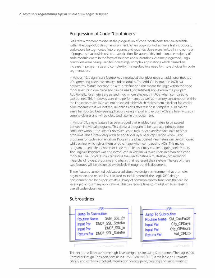
This section will discuss some high-level design tips for using Subroutines. The Logix5000 Controller Design Considerations (Pub# 1756-RM094H-EN-P) is available on Literature Library and contains excellent information on designing, creating and using Routines.

Modular Programming Tips in Studio 5000 Logix Designer | 3
Basic understanding of the topics covered in that reference manual are imperative to properly designing and using Routines.
When to Consider Subroutines:
After a functional specification has been broken down into smaller, less complex operations (code modules) it is time to start deciding which method to utilize to encapsulate each module. When considering Subroutines, it is important to ask the following questions for each proposed code module:
• Is the code module reusable?
• Can the logic for this code module reasonably fit into one routine?
• Is there a relatively small number of tags to be passed to and/or from the code module?
• Does the code module already exist in a legacy controller (PLC-5®, SLC™, or MicroLogix™)?
If the majority of the answers are “yes,” then Subroutines are a great option for that code module. Subroutines have been around for a long time and many users are familiar with how to design and use them. They can be created and used in standard and safety applications and are easily transported between applications which makes them great for building code libraries. Additionally, Subroutines allow the passing of User-Defined Structures (UDT), which makes them very useful when a code module has a corresponding custom defined structure of tags. All input and output Parameters are passed by “value.” This means when the Subroutine is called, input parameter values are passed to the Subroutine. Output Parameters are passed out of the Subroutine after the Subroutine has completed execution. Subroutines are a great option for semi-complex algorithms that can fit into a single routine and may require online editing.
When using Subroutines, remember the following:
• It can be hard to troubleshoot running code when a Subroutine is called from multiple locations. It is highly recommended that users consider adding logic to the application that allows an instance of a Subroutine to be isolated.
• Of all of the available code “containers.” Subroutines require the most overhead to pass Parameters when called. If the application requires the absolute fastest scan-time, consider using other methods.
• If a large number of tags must be passed, consider using UDTs or arrays.
• Subroutines are not global code containers. They can only be called from within the program they reside.
Add-On Instructions

4 | Modular Programming Tips in Studio 5000 Logix Designer
This section will discuss some high-level design tips for using Add-On Instructions (AOIs). The Logix5000 Controller Add-On Instructions Programming Manual (Pub# 1756-PM010F-EN-P) is available on Literature Library and contains excellent information on designing, creating and using AOIs. Basic understanding of the topics covered in that programming manual are imperative to properly designing and using AOIs.
When to Consider AOIs:
When considering AOIs, it is important to ask the following questions for each proposed code module.
• Is the code module reusable?
• Can the logic for this code module reasonably fit into one routine?
• Is there a low probability for online edits?
• Is there a relatively small number of tags to be passed to and/or from the code module?
• Does the user need to quickly know if the code within the module has changed?
• Does the code module require revision control?
If the majority of the answers are “yes,” then AOIs are a great option for that code module. It is important to remember that AOIs are custom instructions that can be created and used in standard and safety applications. They are primarily meant to give users a way to create instructions that are not already available within the Logix5000 design environment. This is a good rule-of-thumb to use when deciding if an algorithm or function is too complex to implement using an AOI. For example, temperature conversions, flow calculations and low-level device control are excellent examples for when an AOI should be considered. These algorithms are similar in complexity and usability when compared to existing instructions like Average (AVE), Timer On Delay (TON) and Count Up Instruction (CTU). On the contrary, an AOI would not be a good choice for a high level, line control algorithm that may contain hundreds or even thousands of rungs and Parameters. In this case, using programs and multiple routines may be a better option. It is also possible for complex functions to be broken down into smaller functions which can be designed into several AOIs. These AOIs can then be embedded (cascaded) within one another to create an AOI for a complex function. These two methods are discussed later in this document. Finally, AOIs are true code “definitions.” This means the code exists in one place, but can be called (instantiated) from anywhere in the application. If the logic in the AOI definition is changed, then that change is reflected anywhere the AOI is used in the application.
When using AOIs, remember the following:
• AOIs cannot be edited while online. Keep this in mind when segmenting code into code modules. If a code module will require regular updates or changes, using subroutines or programs may be a better option.
• AOIs pass Parameters much more efficiently than Subroutines. This is important if high- speed scan times are critical.
• Input and Output Parameters do not support complex structures. If UDTs are used, InOut Parameters are required.
• InOut Parameters pass by reference, so it is possible for that value to change while the AOI is executing.
• Unlike Subroutines, it is very easy to view each instance of AOI logic. This aids in troubleshooting.

Modular Programming Tips in Studio 5000 Logix Designer | 5
• If a large number of tags must be passed to the AOI, consider using UDTs and arrays.
• AOIs are global code modules.
• AOIs are true “definitions.” Instances of an AOI can be called throughout the entire application.
• An AOI can be signed. If any changes are made to the AOI, the signature must be removed. This can provide quick verification of any changes in the instruction.
Programs with ParametersThis section will discuss some high-level design tips for using Programs with Parameters. The Logix5000 Controller Program Parameters Programming Manual (Pub# 1756-PM021A-EN-P) is available on Literature Library and contains excellent information on designing, creating, and using Programs with Parameters. Basic understanding of the topics covered in this programming manual are imperative to properly designing and using programs with Parameters.
Program Parameters is one of the latest features available in the Logix5000 design environment. Each program in an application will now have local tags and Parameters. The primary purpose of Parameters in programs is to add an additional layer of encapsulation by facilitating the sharing of data between programs without the use of Controller Scope tags. Essentially, the user can specifically determine which data remains local (private) to a program and which data is shared (public). Having the ability to clearly define a program’s interface with other programs provides a similar look and feel as AOIs. Programs with Parameters can also exist in safety applications. There are some additional rules that will be in the next section regarding safety application implementation. Let’s take a closer look at the similarities and differences between Programs with Parameters and AOIs.
Key Similarities:
• Input, Output and InOut Parameters are available in Programs and AOIs
• Input, Output and InOut Parameters are passed using the same methods in Programs and AOIs
• Programs and AOIs can be easily transported between projects
• Both Programs and AOIs can be used in safety applications
Key Differences:
• Input and Output Parameters can be complex data types (i.e. arrays, strings, UDTs) in programs
6 | Modular Programming Tips in Studio 5000 Logix Designer
• Public Parameters are only available in programs
• AOIs are true module “Definitions”
• Programs can contain many routines
• Programs can contain all four programming languages
• Programs support online edits
The differences mentioned above give programs a slight advantage over AOIs in certain situations. When determining if a code module should reside in a program, consider the questions below:
• Should the logic be split across multiple routines?
• Does the code module require use of multiple programming languages (simultaneously)?
• Does the code module require Sequential Function Chart (SFC)?
• Is there a high probability for online edits after commissioning?
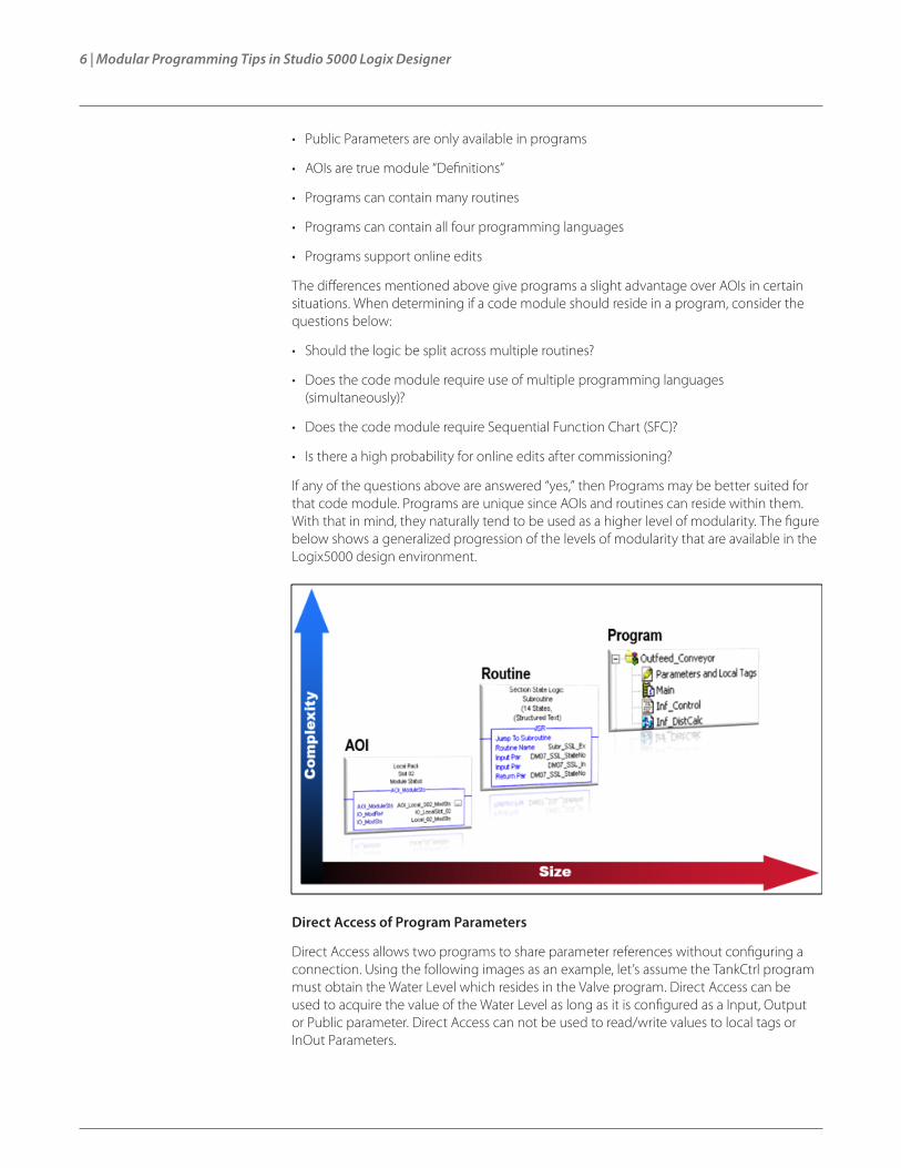
If any of the questions above are answered “yes,” then Programs may be better suited for that code module. Programs are unique since AOIs and routines can reside within them. With that in mind, they naturally tend to be used as a higher level of modularity. The figure below shows a generalized progression of the levels of modularity that are available in the Logix5000 design environment.
Direct Access of Program Parameters
Direct Access allows two programs to share parameter references without configuring a connection. Using the following images as an example, let’s assume the TankCtrl program must obtain the Water Level which resides in the Valve program. Direct Access can be used to acquire the value of the Water Level as long as it is configured as a Input, Output or Public parameter. Direct Access can not be used to read/write values to local tags or InOut Parameters.

Modular Programming Tips in Studio 5000 Logix Designer | 7
The image below shows a syntax example of how a user would use Direct Access in the TankCtrl program to obtain the Water Level value in the Valve program. In this example, the instruction below would reside in the TankCtrl program.
Direct Access supports read capabilities for Input, Output and Public Parameters. Additionally, Direct Access supports write capabilities to Input and Public Parameters. Direct Access occurs in real-time and is un-buffered. All programming languages support Direct Access of program Parameters.
Interface Layer Design RecommendationsCode modules have several main components. Besides the actual code, nearly all modules must have a clearly defined interface. The interface layer will encompass all of the inputs and outputs the code module requires to operate. This includes connections to physical I/O, field devices and/or other code modules. This section will be covering design tips and examples of how Parameters can be used to design the interface layer for a code module.
Input Parameters:
Input Parameters are primarily used for data that must flow IN to a code module. Input Parameters are passed by value, meaning the data is passed when the subroutine, program or AOI is called. If the data connected to an Input Parameter is changed by a higher priority task while executing the code module, it will not be updated in the current execution of the code module until it is called again. Users will no longer have to “buffer” input data to prevent updates during program execution. Additionally, only ONE connection can be made to an Input Parameter. If multiple code modules must have access to an Input Parameter, then a separate Input Parameter must be created for each connection. Direct Access could be used to avoid the use of multiple Input Parameters for one function within a code module. This concept is known as “fanning.” The table highlights the behavior differences between Subroutines, Programs and AOIs when using Input Parameters.

8 | Modular Programming Tips in Studio 5000 Logix Designer
Input Parameters
Subroutine AOI Program
Passed by Value Yes Yes Yes
Passed by Reference No No No
Connections Supported 1 1 1*
Parameters Supported 40 Unlimited 512**
Atomic Data Types Yes Yes Yes
Structures (UDTs) / Arrays Yes No Yes
Online Changes to Parameter Reference or Connection Yes Yes Yes
* Direct Access could be used to simulate “fanning”
** 512 is the total count of all Parameters for one program
Examples:
• Passing Input module data to a code module
• Any operation that can be invoked by other code modules
• Passing data from an HMI to a code module
Output Parameters:
Output Parameters are primarily used for data that must flow OUT of a code module. Output Parameters are passed by value, meaning the data is passed when the program or AOI execution is complete. Multiple connections can be made to a single Output parameter (this is known as “fanning”). Unlike Input Parameters, multiple code modules can have connections to a single Output parameter. The summary below highlights the behavior differences between Subroutines, Programs and AOIs when using Output Parameters.
Output Parameters
Subroutine AOI Program
Passed by Value Yes Yes Yes
Passed by Reference No No No
Connections Supported 1 1 512*
Parameters Supported 40 Unlimited 512**
Atomic Data Types Yes Yes Yes
Structures (UDTs) / Arrays Yes No Yes
Online Changes to Parameter Reference or Connection Yes Yes Yes
* This includes all connections to a parameters (member and sub-member)
** 512 is the total count of all parameters for one program
Examples:
• Passing data from a code module to an Output module
• Invoking operations in other code modules
• Allowing code module public attributes (i.e. Values, Statuses) to be accessible to other code modules

Modular Programming Tips in Studio 5000 Logix Designer | 9
InOut Parameters:
InOut Parameters are primarily used for data that must be acquired and/or updated in real-time. Because InOut Parameters are passed by reference rather than by value, they are merely a pointer to the original data and closely resemble the behavior of an alias tag. With this in mind, it is possible for InOut Parameter values to change during execution of the code module. For both AOIs and Programs, InOut Parameters can only have ONE connection. The summary below highlights the behavior differences between Programs and AOIs when using InOut Parameters.
InOut Parameters
Subroutine AOI Program
Passed by Value n/a No No
Passed by Reference n/a Yes Yes
Connections Supported n/a 1 1
Parameters Supported n/a 40 512*
Atomic Data Types n/a Yes Yes
Structures (UDTs) / Arrays n/a Yes Yes
Online Changes to Parameter Reference or Connection n/a Yes Yes**
* 512 is the total count of all parameters for one program.
** InOut Parameter connections support online edits only using Partial Import Online (PIO)
Examples:
• Required when using a Message instruction in an AOI
• Required when passing any UDT structure or array into an AOI
• Connections to I/O Module status information (Allows the code module to monitor real-time information)
Public Parameters:
Public Parameters are only available for programs and are primarily used for data that must be available to all code modules. Public Parameters have the look and feel of controller scope tags, however, they reside at the program scope. This makes Public Parameters an excellent option for tag data that must be globally available (Read/Write) for other code modules. When a Public Parameter changes value within a code module, it is immediately available to higher priority tasks that are connected to that Parameter. Additionally, multiple connections can be configured to a public parameter. Multiple connections can also be made to members of a Public Parameter, including UDTs, Arrays and bits of an atomic data type (i.e.: Signed Integer (INT), Double Integer (DINT) and Signed Short Integer (SINT)). The summary below highlights design considerations for using Public Parameters.

10 | Modular Programming Tips in Studio 5000 Logix Designer
Public Parameters
Subroutine AOI Program
Passed by Value n/a n/a Yes
Passed by Reference n/a n/a See Note*
Connections Supported n/a n/a 512**
Parameters Supported n/a n/a 512***
Atomic Data Types n/a n/a Yes
Structures (UDTs) / Arrays n/a n/a Yes
Online Changes to Parameter Reference or Connection n/a n/a Yes
* Public Parameters are updated in real-time from within the program where they reside
** This includes all connections to a parameter (member and sub-member).
*** 512 is the total count of all parameters for one program
Examples:
• Code module public attributes (i.e. Statuses, Values)
Standard/Safety Applications:
Program Parameters can support many types of connections. The tables below show a quick reference of valid configurations when defining connections between two standard programs or two safety programs.
* An InOut Parameter may only be connected to an Output Parameter if the InOut Parameter is configured as a Constant.
Safety Applications:
There are some special rules that must be considered when implementing Program Parameters within a safety application. This section will briefly discuss this topic. Under no circumstances should code reside in a standard program to overwrite data in a safety program (unless safety mapping is configured). Standard programs can only read data from a safety program. Standard program Input Parameters can only connect to safety program Output and Public Parameters. Standard Input Parameters can also be connected to safety tags at the controller scope. The table shows a quick reference of valid connections between standard and safety programs.
Modular Programming Tips in Studio 5000 Logix Designer | 11
Embedding Levels of Modularity It is common for large complex algorithms to be broken down into many smaller, less complex code modules. In many cases, the smaller code modules can be embedded (or cascaded) with one another in an effort to maintain a hierarchy of encapsulation. Subroutines, AOIs and Programs all support embedding and can be highly utilized for organization, ease of development and code reuse. This section will focus on the three code containers as it pertains to embedding. Several design examples will be discussed to show how embedding can be designed and implemented.
AOIs and Subroutines can be nested up to 25 levels. Only under rare circumstances would this limit ever be reached. In most cases, three to five levels is more than sufficient especially when AOIs are used in conjunction with subroutines. When using subroutines, remember that they are not global entities. This means they can only be called from within the program where they reside. Subroutines also require the most controller resources to pass Parameters to and from the routine. If an application requires the absolute fastest scan time, then subroutines should be used sparingly. Subroutines do have some significant advantages. Subroutines are supported by legacy controllers including SLC, MicroLogix and PLC-5. This allows users to quickly convert reusable code from legacy controllers to be used in the latest Logix5000 design environment. Additionally, subroutines can be edited online.
Unlike Subroutines, AOIs are global and can be called from anywhere in the application. The mechanism used for passing Parameters in and out of an AOI are also much more efficient than Subroutines. This results in faster execution. AOIs offer built in revision control as well as giving users the opportunity to seal the logic with a signature. This will allow users to quickly determine if an AOI has been changed. AOIs also allow users to develop instruction help information so end users are able to quickly find information on how to configure or use a particular instruction. Additionally, when using AOIs, remember that they do not support online edits.
Of the three code containers within the Logix5000 design environment, Programs are the only container that cannot be embedded in other programs from an execution perspective. Programs are the highest level of modularity this document analyzes. Routines and AOIs live in programs, which clearly supports the concept of embedding. Parameters can be leveraged in programs to expose outside data directly to lower level code modules like AOIs and Subroutines. Let’s take a look at a few examples of how different levels of modularity can be embedded to produce an organized solution that is easy to troubleshoot and completely reusable.
AOI Embedded in a Program:
In this example, let’s assume we have a baking application that has oven temperature control broken into zones. At the highest level, we have a program named Zone_01. Within that program, there are several routines which contain the logic required for monitoring and controlling the temperature. Let’s assume the application requires the Zone_01 entry temperature to be converted from Celsius to Fahrenheit. First, we can create an Input Parameter at the program level and make a connection to the entire thermocouple structure. The image shows an example of this connection.

12 | Modular Programming Tips in Studio 5000 Logix Designer
Next we create or reuse an AOI that converts Celsius to Farenheit.
Finally, we instantiate the AOI in the CM_EntryTemp routine and directly reference the program input parameter as the AOI temperature input. In this example, Channel 1 contains the Zone 1 entry temperature.
AOI Embedded in an AOI:
In this example, the T_EQU (Time Equal) AOI is used from the PlantPAx library. This AOI compares two Date-and-Time-of-Day (DateTime) variables and will set the “Output” bit if they are equal. The algorithm for T_EQU must add a time value to the two DateTime variables. To do this, an additional AOI is embedded in the T_EQU AOI. Let’s take a look at the example:
When a user imports the T_EQU AOI into an application, all AOIs that are embedded are also imported. The image to the left shows the Add-On Instructions folder after the T_EQU AOI was imported.
The T_EQU AOI calls the T_ADD AOI. The image below shows the rung that calls the T_ADD AOI.
This AOI will have two parameters, Temp_IN_C and Temp_OUT_F.
The backing tags and parameters for these two instances reside within the T_EQU AOI.
Zone_01 Program Properties
Input Parameter created. The data type is the module defined tag for the thermocouple module.
Connection is made to the thermocouple module input tag (controller scope).

Modular Programming Tips in Studio 5000 Logix Designer | 13
The image below shows an instance of the T_EQU AOI. This example takes a complex process and breaks it into smaller, more manageable pieces. After code modules are developed to solve each small piece, they are reassembled to provide a solution for the original problem statement.
Logical Organizer In Studio 5000 Logix Designer Version 24, the “Logical Organizer” was introduced. The Logical Organizer allows users to create a multi-level, organizational hierarchy of folders, programs and phases to represent their system. This provides a paradigm shift from how the “controller executes code” to how the “user views the system.” Users will have the ability to create, edit or delete programs from the Logical Organizer. This resembles the existing functionally available in the Controller Organizer. The Logical Organizer also allows you to drag/drop programs and program structures (sub-programs) within the same application or across multiple instances of Studio 5000 Logix Designer. This is particularly powerful if a code library is in the form of an ACD file. Additionally, the Logical Organizer hierarchy is stored in the controller and is recoverable on an upload. This section will cover a simple example of how the Logical Organizer can be implemented to organize applications.
Baking Example
The images below show a good representation of the Controller Organizer (execution view) and the Logical Organizer (system view). The Controller Organizer shows each task and the programs that are to be executed in that task. In many cases, code modules that are not related will exist in the same task. This can make troubleshooting tricky for someone who is not familiar with the program structure. The Logical Organizer allows the user to group programs into a logical hierarchy that makes it much easier for someone familiar with the system or process to find code quickly.
This AOI appears clean and simple. It utilizes other smaller code modules (AOIs) to solve a complex problem.
PreMix equipment module lives in the PreMix Unit module. Both are programs.
Mixers and Outfeed_Conveyors live in same task in the Controller Organizer. They are in two different Unit folders in the Logical Organizer.
All programs associated with the Vertical Form, Fill, and Seal process are grouped in one folder.
14 | Modular Programming Tips in Studio 5000 Logix Designer
Remember, complex folder and program structures support import/export. Additionally, folders and programs support drag and drop from within an application or across multiple instances of Studio 5000® (Version 24). Right-click, drag and drop (with configuration) implements a “deep” copy. This imports all sub folders, programs, AOIs and associated data structures. This makes ACD files a great repository for code modules.
Controller Performance Considerations The following section will walk through three examples comparing the performance of Subroutines, AOIs and Programs. The scan-times shown will reflect the amount of time taken to pass the Parameters into and out of the code container. This scan time will be dynamic; varying depending on the type and number of Parameters configured.
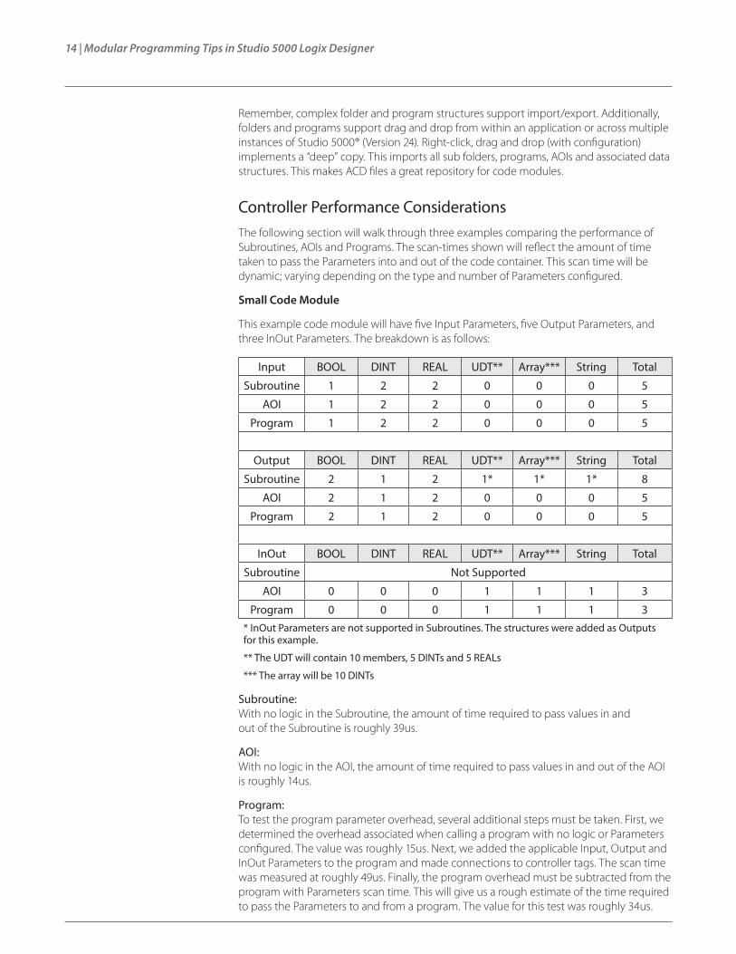
Small Code Module
This example code module will have five Input Parameters, five Output Parameters, and three InOut Parameters. The breakdown is as follows:
Input BOOL DINT REAL UDT** Array*** String Total
Subroutine 1 2 2 0 0 0 5
AOI 1 2 2 0 0 0 5
Program 1 2 2 0 0 0 5
Output BOOL DINT REAL UDT** Array*** String Total
Subroutine 2 1 2 1* 1* 1* 8
AOI 2 1 2 0 0 0 5
Program 2 1 2 0 0 0 5
InOut BOOL DINT REAL UDT** Array*** String Total
Subroutine Not Supported
AOI 0 0 0 1 1 1 3
Program 0 0 0 1 1 1 3* InOut Parameters are not supported in Subroutines. The structures were added as Outputs for this example.
** The UDT will contain 10 members, 5 DINTs and 5 REALs
*** The array will be 10 DINTs
Subroutine: With no logic in the Subroutine, the amount of time required to pass values in and out of the Subroutine is roughly 39us.
AOI: With no logic in the AOI, the amount of time required to pass values in and out of the AOI is roughly 14us.
Program: To test the program parameter overhead, several additional steps must be taken. First, we determined the overhead associated when calling a program with no logic or Parameters configured. The value was roughly 15us. Next, we added the applicable Input, Output and InOut Parameters to the program and made connections to controller tags. The scan time was measured at roughly 49us. Finally, the program overhead must be subtracted from the program with Parameters scan time. This will give us a rough estimate of the time required to pass the Parameters to and from a program. The value for this test was roughly 34us.

Modular Programming Tips in Studio 5000 Logix Designer | 15
Medium Code Module
This example code module will have 10 Input Parameters, 10 Output Parameters, and 20 InOut Parameters. The breakdown is as follows:
Input BOOL DINT REAL UDT** Array*** String Total
Subroutine 2 4 4 5* 4* 1* 20
AOI 2 4 4 0 0 0 10
Program 2 4 4 0 0 0 10
Output BOOL DINT REAL UDT** Array*** String Total
Subroutine 3 2 5 5* 3* 2* 20
AOI 3 2 5 0 0 0 10
Program 3 2 5 0 0 0 10
InOut BOOL DINT REAL UDT** Array*** String Total
Subroutine Not Supported
AOI 0 0 0 10 7 3 20
Program 0 0 0 10 7 3 20* InOut Parameters are not supported in Subroutines. The structures were added as Outputs for this example.
** The UDT will contain 10 members, 5 DINTs and 5 REALs
*** The array will be 10 DINTs
Subroutine: With no logic in the Subroutine, the amount of time required to pass values in and out of the Subroutine is roughly 140us.
AOI: With no logic in the AOI, the amount of time required to pass values in and out of the AOI is roughly 42us.
Program: To test the program parameter overhead, several addition steps must be taken. First, we determined the overhead associated with calling a program with no logic or Parameters configured. The value was roughly 15us. Next, we added the applicable Input, Output and InOut Parameters to the program and made connections to controller tags. The scan time was measured at roughly 65us. Finally, the program overhead must be subtracted from the program with Parameters scan time. This will give us a rough estimate of the time required to pass the Parameters to and from a program. The value for this test was roughly 50us.

16 | Modular Programming Tips in Studio 5000 Logix Designer
Large Code Module
This example code module will have 20 Input Parameters, 20 Output Parameters, and 40 InOut Parameters. The breakdown is as follows:
Input BOOL DINT REAL UDT** Array*** String Total
Subroutine 4 8 8 10* 5* 5* 40
AOI 4 8 8 0 0 0 20
Program 4 8 8 0 0 0 20
Output BOOL DINT REAL UDT** Array*** String Total
Subroutine 6 4 10 10* 5* 5* 40
AOI 6 4 10 0 0 0 20
Program 6 4 10 0 0 0 20
InOut BOOL DINT REAL UDT** Array*** String Total
Subroutine Not Supported
AOI 0 0 0 20 10 10 40
Program 0 0 0 20 10 10 40
* InOut Parameters are not supported in Subroutines. The structures were added as Outputs for this example.
** The UDT will contain 10 members, 5 DINTs and 5 REALs
*** The array will be 10 DINTs
Subroutine: With no logic in the Subroutine, the amount of time required to pass values in and out of the Subroutine is roughly 299us.
AOI: With no logic in the AOI, the amount of time required to pass values in and out of the AOI is roughly 68us.
Program: To test the program parameter overhead, several addition steps must be taken. First, we determined the overhead associated with calling a program with no logic or Parameters configured. The value was roughly 15us. Next, we added the applicable Input, Output and InOut Parameters to the program and made connections to controller tags. The scan time was measured at roughly 95us. Finally, the program overhead must be subtracted from the program with Parameters scan time. This will give us a rough estimate of the time required to pass the Parameters to and from a program. The value for this test was roughly 80us.

Modular Programming Tips in Studio 5000 Logix Designer | 17
Test Results
The figure below indicates that subroutines require the most overhead in the controller to pass Parameters to and from a subroutine. The tests above could have been optimized by “packing” most of the individual Input and Output Parameters for a Subroutine into a UDT. This would have reduced the amount of separate Parameters being passed. However, to get a true “apples to apples” comparison, the parameter structure was designed as closely as possible across the three code containers.
AOIs require the least amount of overhead to pass Parameters, especially if InOut Parameters are used. Programs with Parameters are slightly slower than AOIs. As the size of the code module increases, the disparity in overhead between AOIs and Programs becomes less apparent. Our tests above indicate that a program by itself will introduce a small amount of overhead. From a pure scan-time performance perspective, small code modules should be designed in AOIs and placed into higher-level Programs. This will reduce the overall number of small programs in an application, thus optimizing scan time performance.
Each container has clear advantages when implemented properly for certain use-cases. Knowing how each container operates will help users choose the correct combination to take full advantage of the positive synergies between code modules. Using all three methods can significantly increase code performance, robustness and reusability. Ultimately, it is up to the user to determine which methods to use when designing an application. In most cases, there is more than one viable solution.

18 | Modular Programming Tips in Studio 5000 Logix Designer
Allen-Bradley, ControlLogix, FactoryTalk and Rockwell Automation are trademarks of Rockwell Automation Inc.Microsoft and Azure are trademarks of the Microsoft Corporation.
Publication 9324-WP007A-EN-P – August 2015 Copyright © 2015 Rockwell Automation, Inc. All Rights Reserved. Printed in USA.