Modular Products Product Specification - Digi-Key Sheets/Stewart Connector PDFs... · 6.0 Soldering...
14
Stewart Connector Stewart Connector 11118 Susquehanna Trail South Glen Rock, Pa. 17327-9199 Ph: (717) 235-7512 Fax: (717) 235-4675 Product Specification PR022-01 http://www.stewartconnector.com Page 1 of 14 Date: 3-2-16 Revision: C0 Product Specification PR022-01 Revision C0 3/2/2016 Modular Products
-
Upload
duongnguyet -
Category
Documents
-
view
227 -
download
2
Transcript of Modular Products Product Specification - Digi-Key Sheets/Stewart Connector PDFs... · 6.0 Soldering...

Stewart Connector
Stewart Connector 11118 Susquehanna Trail South
Glen Rock, Pa. 17327-9199
Ph: (717) 235-7512 Fax: (717) 235-4675
Product Specification PR022-01
http://www.stewartconnector.com Page 1 of 14 Date: 3-2-16 Revision: C0
Product Specification
PR022-01
Revision C0 3/2/2016
Modular Products
Stewart Connector
Modular Connectors Product Specification PR022-01
http://www.stewartconnector.com Page 2 of 14 Date: 3-2-16 Revision: C0
1.0 Objective
This document establishes the performance requirements and outlines qualification tests for shielded and
unshielded modular connectors produced by Stewart Connector. These products are intended to be
soldered onto a printed circuit board or terminated onto a cable and mated to a compatible Stewart
Connector modular product.
2.0 Scope
This specification is applicable to shielded and unshielded modular products.
3.0 General
This document is comprised of the following sections (specifications subject to change without notice):
Paragraph Title
1.0 Objective
2.0 Scope
3.0 General
Table 1 Qualification Test Matrix
4.0 Applicable Documents
Table 2 IEC Modular Plug and Jack Standards
5.0 General Requirements
6.0 Soldering Process Requirements
Table 3 Wave Solder
Figure 1 IR Reflow Profile
7.0 Quality Assurance Provisions
Table 4 Inspection Conditions
8.0 Requalification of Products
9.0 Electrical Requirements
Table 5 LLCR
Figure 2 Bulk Contact Interface LLCR Measurement
Figure 3 Bulk Shield Interface LLCR Measurement
Figure 4 LLCR Measurement Configuration
Table 6 Insulation Resistance
Table 7 DWV (Adjacent Contacts)
Table 8 DWV (Contacts to Shield)
10.0 Mechanical Requirements
Table 9 Mechanical Durability
Table 10 Gauging – Go Gauges
Table 11 Mating / Unmating Force
Figure 5 Discontinuity Configuration
Table 12 Mechanical Shock
Table 13 Sinusoidal Vibration
Table 14 Random Vibration
Table 15 Rotational Test
11.0 Environmental Conditions
Table 16 Temperature Life
Table 17 Thermal Shock
Table 18 Temperature / Humidity
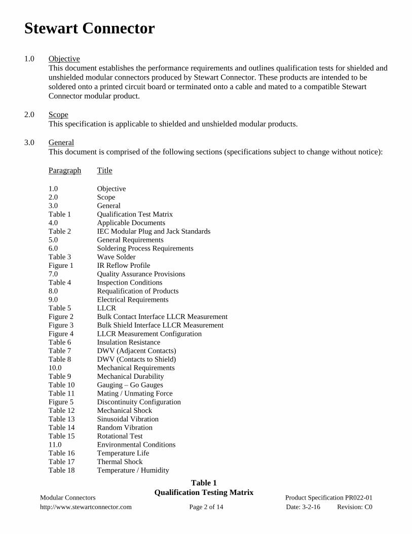
Table 1
Qualification Testing Matrix

Stewart Connector
Modular Connectors Product Specification PR022-01
http://www.stewartconnector.com Page 3 of 14 Date: 3-2-16 Revision: C0
Qualification
Testing Matrix 1 2 3 4 5 6 7 8 (4) 9
Test Para.
Examination of Product 5.5 1,5 1,5 1,7 1,7 1,5 1,6 1,8 1,5 1,3
Low Level Contact Resistance 9.1 2,4 2,4 2,6 2,4 2,4 2,4 2,4
Temperature Rise vs. Current 9.2 3
Durability 10.1 3
Gaging 10.2 2
PCB Insertion Force 10.3 3
Mating / Unmating Force 10.4 4
Discontinuity 10.5 5
Latch Strength 10.6 6
Mechanical Shock 10.7 5
Vibration (Sinusoidal) 10.8 3
Vibration (Random) 10.9 4
Temperature Life 11.1 3
Thermal Shock 11.2 3
Temperature/Humidity 11.3 3
Insulation Resistance 9.3 5 5
D. W. V. (Adj. Contacts) (2) 9.4 6
D. W. V. (Contacts-Shield) (1,2) 9.5 7
RJ-11 Insertion (4) 10.10 3
Rotational Test 10.11 2
Note: 1 Only Applies to Shielded Product
2 DWV stands for Dielectric Withstand Voltage
3 Numbers indicate sequence in which tests are performed.
4 Test Group 8 Applies to RJ-45 style jacks only
Test Groups
Testing Sequence (3)

Stewart Connector
Modular Connectors Product Specification PR022-01
http://www.stewartconnector.com Page 4 of 14 Date: 3-2-16 Revision: C0
4.0 Applicable Documents
4.1 Stewart Connector Specifications:
4.1.1 Product Drawings
4.1.2 Customer Drawings
4.1.3 Test Specifications
4.2 Other Standards and Specifications (Applicable in Part):
4.2.1 UL94V-0 Flammability
4.2.2 EIA-364
4.2.3 EIA/TIA-568
4.2.4 EIA/TIA-570
4.2.5 IEC 60603-7
4.2.6 TIA 1096
4.2.7 IEEE 802.3
Table 2
IEC Modular Plug and Jack Standards
Category Type Standard
Base
Specification
UTP IEC 60603-7
ScTP IEC 60603-7-1
Category 5e UTP IEC 60603-7-2
Category 5e ScTP IEC 60603-7-3
Category 6 UTP IEC 60603-7-4
Category 6 ScTP IEC 60603-7-5
UTP – Unshielded Twisted Pair
ScTP – Screened Twisted Pair
Additional specifications and standards may be referenced as applicable. The latest revisions of
the above specifications available at the date of issue of this specification are used unless
otherwise indicated.

Stewart Connector
Modular Connectors Product Specification PR022-01
http://www.stewartconnector.com Page 5 of 14 Date: 3-2-16 Revision: C0
5.0 General Requirements
5.1 Qualification:
Connectors furnished under this specification shall be capable of meeting the qualification test
requirements specified herein.
5.2 Material:
5.2.1 Plastic Housings: UL94V-0
5.2.2 Contacts: Copper Alloy
5.2.3 Shield: Copper Alloy
5.3 Finish:
5.3.1 Contacts: Gold Selectively Plated
5.3.2 Contacts: Nickel Plated All Over
5.3.3 Reference Customer Drawing for Contact Solder Tails
5.3.4 Shield: Tin or Nickel Plated All Over
5.4 Design and Construction:
Connectors shall be of the design, construction and physical dimensions as specified on the
applicable product drawing and TIA 1096. In case of conflict between this specification and
product drawings, the drawings shall take precedence. 50 inch (1.27 m) gold plated
connectors compliant with TIA 1096 specifications.
5.5 Examination of Product:
Connectors shall meet all specified dimensions of product drawings and internal workmanship
standards. There shall be no evidence of cracking, chipping, contamination or loose parts when
inspected, without magnification, to the unaided eye.
5.6 Operating and Storage Temperature Range: -40°C to 85°C
5.7 Ratings:
5.7.1 Current: 1.5 amperes maximum at 25C
5.7.2 Voltage: 150 VAC maximum
5.8 Minimum Number of Mating/Unmating Operations:
5.8.1 Performance Level 1: 750 Cycles
5.8.2 Performance Level 2: 2500 Cycles
5.9 Minimum Number of Cable Re-Terminations:
5.9.1 Refer to application drawings

Stewart Connector
Modular Connectors Product Specification PR022-01
http://www.stewartconnector.com Page 6 of 14 Date: 3-2-16 Revision: C0
IR Reflow Profile
0
50
100
150
200
250
300
0 40 80 120 160 200 240 280 320 360
Time (seconds)
Tem
pera
ture
(D
eg
rees C
)
380
260
6.0 Soldering Process Requirements
6.1 Wave Solder:
Modular connectors are capable of withstanding wave solder temperatures without any functional
deterioration. See Table 3 below:
Table 3
Wave Solder Process Profile Maximum
Temperature
Maximum Temperature
Exposure Time
Low-Temp Products 428F (220C) 10 Seconds
High-Temp Products 500F (260C) 10 Seconds
6.2 IR Reflow Solder:
High-temperature modular connectors are capable of withstanding non-focused infrared (IR)
reflow and equivalents at up to 500F (260C) without any functional deterioration. The
modular jacks shall be exposed to profiles as specified in Figure 1 below:
* Note: IR Profile may not apply to products with LEDs or light pipes. Please consult factory
for specifics.
FIGURE 1
Stewart Connector
Modular Connectors Product Specification PR022-01
http://www.stewartconnector.com Page 7 of 14 Date: 3-2-16 Revision: C0
7.0 Quality Assurance Provisions
7.1 Equipment Calibration:
All test equipment and inspection facilities used in the performance of any test shall be
maintained and calibrated in accordance with Stewart Connector Operating Procedures and/or
other applicable specifications.
7.2 Inspection Conditions:
Unless otherwise specified, all inspections shall be performed under the conditions noted.
See Table 2 below:
Table 4
Inspection Conditions Temperature
(±5 ºC)
Relative
Humidity
(%)
Barometric
Pressure
25 30 to 50 Local Ambient
7.3 Sample Quantity and Description:
The test samples required for groups 1 through 9 in Table 1 shall be chosen to comprise a group
that consists of 80 contacts, on 10 ports, on two connectors minimum. For samples with multiple
contact designs, there shall be 20 examples minimum of each individual contact design.
Test group 8 is only applicable to 8 and 10 position RJ-45 style jacks.
The test samples required for group 10 in Table 1 shall be chosen to comprise a group that
consists of 16 total contacts on 2 connectors minimum.
7.4 Acceptance:
7.4.1 All samples tested in accordance with this product specification shall meet the stated
requirements.
7.4.2 Failures attributed to equipment, test set-up, sample preparation problems, contaminants
or operator error, should not disqualify the product. Corrective action will be taken and
samples re-submitted for qualification.
8.0 Requalification of Products
8.1 Requalification Testing
If changes are made to the product, design or manufacturing process after initial product
qualification that are judged by the management of Stewart Connector to materially affect the
product form, fit or function, then new product samples shall be subject to full or partial
requalification testing.

Stewart Connector
Modular Connectors Product Specification PR022-01
http://www.stewartconnector.com Page 8 of 14 Date: 3-2-16 Revision: C0
9.0 Electrical Requirements
9.1 Low Level Contact Resistance (Board Mounted Product):
LLCR should be measured (mated with a Stewart Connector plug) in accordance
with EIA-364-23 with a test current of 100 mA and a maximum open circuit voltage of 20
mVDC (dry circuit test). See Table 5 below:
Table 5
Low Level Contact Resistance Contacts Shield Interface **
Initial
(m)
Final
(m)
Initial
(m)
Final
(m)
100 * 20 20 40
All values listed are maximum values.
* 100 m Initial LLCR Includes Bulk
** Shield Interface LLCR Not Applicable to Unshielded Connectors
Low Level Contact Resistance (LLCR) is measured on a mated Plug and Jack.
Measurements are generally performed before and after environmental exposure or
mechanical conditioning. Bulk LLCR is measured between a mated Plug conductor and
Jack printed wiring board (PWB) pin. Bulk resistance consists of the following four (4)
components. Refer to Figure 2 below.
Contacts RBulk = Rab+Rbc+Rcd+Rde
(1) (Rab) Plug Conductor Resistance
(2) (Rbc) Plug Blade/Conductor Contact Resistance
(3) (Rcd) Plug Blade/Jack Wire Contact Resistance
(4) (Rde) Jack Wire Resistance
a
e
b
c
d
FIGURE 2
Bulk Low Level Contact Resistance
(LLCR)

Stewart Connector
Modular Connectors Product Specification PR022-01
http://www.stewartconnector.com Page 9 of 14 Date: 3-2-16 Revision: C0
9.1 Low Level Contact Resistance: (Cont.)
Shield Interface RBulk = Rab+Rbc+Rcd+Rde
(1) (Rab) Jack Shield Resistance
(2) (Rbc) Jack Shield/Plug Shield Contact Resistance
(3) (Rcd) Plug Shield/Cable Shield Contact Resistance
(4) (Rde) Cable Shield Resistance
Typical Bulk contact resistance of a mated plug and jack can range between 20 to 50 m.
Stewart Connector product specification requirement is a bulk contact resistance change
after conditioning. In most cases, the maximum allowable change in bulk contact resistance
after environmental conditioning is 20 m.
LLCR measurements are conducted utilizing a four (4) wire dry circuit test method.
Implementation consists of a 100 mA DC current source with a maximum open circuit
voltage of 20 mV. Measurements are performed using low current and voltage levels to
preserve oxides and films that may form during environmental conditioning.
In practice, Jacks are mounted on PWB boards, which are design to interface with
automated switching and measuring equipment. Stewart Connector LLCR measuring
system consists of a Micro-Ohmmeter and a Hewlett Packard Data Acquisition Switch Unit.
Automation software is utilized to fully control the measurement sequence. Refer to
measurement configuration in Figure 4 below.
FIGURE 3
a e b2
c2
d
Shield Interface Bulk Low Level Contact Resistance
(LLCR)
c1
b1

Stewart Connector
Modular Connectors Product Specification PR022-01
http://www.stewartconnector.com Page 10 of 14 Date: 3-2-16 Revision: C0
9.1 Low Level Contact Resistance: (Cont.)
9.2 Temperature Rise versus Current:
The temperature rise above ambient (25C) shall not exceed 30 C at any point on the
connector when all contacts are powered in series with 1.5 Amps DC in accordance with
EIA-364-70.
9.3 Insulation Resistance:
The insulation resistance of the unmated connectors shall be measured in accordance with
EIA-364-21. See Table 6 below:
Table 6
Insulation Resistance Test Voltage
(VDC)
Test Duration
(Minutes)
Requirement
(M)
Points of Measurement
500 1 500 Between adjacent contacts
500 1 500 Between contacts and shield**
** Not Applicable to Unshielded Connectors
FIGURE 4
Stewart Connector
Modular Connectors Product Specification PR022-01
http://www.stewartconnector.com Page 11 of 14 Date: 3-2-16 Revision: C0
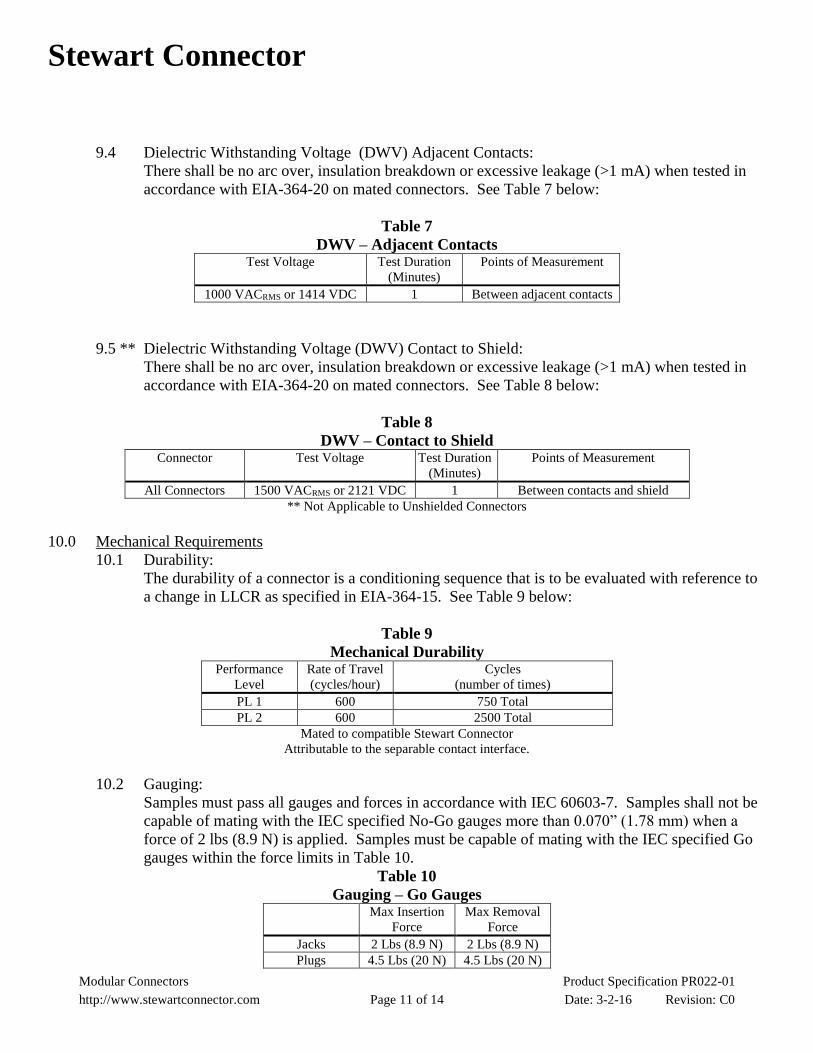
9.4 Dielectric Withstanding Voltage (DWV) Adjacent Contacts:
There shall be no arc over, insulation breakdown or excessive leakage (>1 mA) when tested in
accordance with EIA-364-20 on mated connectors. See Table 7 below:
Table 7
DWV – Adjacent Contacts Test Voltage Test Duration
(Minutes)
Points of Measurement
1000 VACRMS or 1414 VDC 1 Between adjacent contacts
9.5 ** Dielectric Withstanding Voltage (DWV) Contact to Shield:
There shall be no arc over, insulation breakdown or excessive leakage (>1 mA) when tested in
accordance with EIA-364-20 on mated connectors. See Table 8 below:
Table 8
DWV – Contact to Shield Connector Test Voltage Test Duration
(Minutes)
Points of Measurement
All Connectors 1500 VACRMS or 2121 VDC 1 Between contacts and shield
** Not Applicable to Unshielded Connectors
10.0 Mechanical Requirements
10.1 Durability:
The durability of a connector is a conditioning sequence that is to be evaluated with reference to
a change in LLCR as specified in EIA-364-15. See Table 9 below:
Table 9
Mechanical Durability Performance
Level
Rate of Travel
(cycles/hour)
Cycles
(number of times)
PL 1 600 750 Total
PL 2 600 2500 Total
Mated to compatible Stewart Connector
Attributable to the separable contact interface.
10.2 Gauging:
Samples must pass all gauges and forces in accordance with IEC 60603-7. Samples shall not be
capable of mating with the IEC specified No-Go gauges more than 0.070” (1.78 mm) when a
force of 2 lbs (8.9 N) is applied. Samples must be capable of mating with the IEC specified Go
gauges within the force limits in Table 10.
Table 10
Gauging – Go Gauges Max Insertion
Force
Max Removal
Force
Jacks 2 Lbs (8.9 N) 2 Lbs (8.9 N)
Plugs 4.5 Lbs (20 N) 4.5 Lbs (20 N)

Stewart Connector
Modular Connectors Product Specification PR022-01
http://www.stewartconnector.com Page 12 of 14 Date: 3-2-16 Revision: C0
10.3 PCB Insertion Force:
A connector, not including shield solder tails or signal contacts, shall require no more than 15 lbs
(67 N) of insertion force when inserted into a minimum sized PCB hole specified on the
customer print when using pushing force rate of 0.5 inches (12.7 mm) per minute.
10.4 Mating / Unmating Force.
Mating and Unmating forces are to be measured after one cycle pre-conditioning as specified in
IEC 60603-7. See Table 11 below:
Table 11
Mating / Unmating Force Item Speed Mating Force Unmating Force
Unshielded Modular
Connector
0.4 inch/sec,
10.16 mm/sec
4.5 lbs,
20 N
4.5 lbs,
20 N
Shielded Modular
Connector
0.4 inch/sec,
10.16 mm/sec
6.7 lbs,
30 N
6.7 lbs,
30 N
All values listed are maximum values.
Modular plug tested with the latch depressed.
10.5 Discontinuity:
The mated pair shall have no discontinuities greater than 10 s when pulled against the plastic
walls in the lower (opposite latch tab) position with 4.5 lbs (20 N) minimum applied in the axial
direction. Gauge dimensions and test details are in accordance with IEC 60603-7, Annex A. See
Figure 5 below:
10.6 Latch Strength.
Latch Strength will be measured in accordance with EIA-364-98. Samples shall be mounted in a
panel cutout as specified on the Customer Print as applicable. The connected pair shall
withstand an axial load of 20 pounds minimum at a rate of 0.5 inches per minute.
Discontinuity Meter
Insulating Block
4.5 lbs
(20 N)
FIGURE 5

Stewart Connector
Modular Connectors Product Specification PR022-01
http://www.stewartconnector.com Page 13 of 14 Date: 3-2-16 Revision: C0
10.7 Mechanical Shock:
Mechanical Shock shall be measured in accordance with EIA-364-27, condition A, with
assembled connectors mounted rigidly to table and no discontinuities of >1 microsecond. See
Table 12 below:
Table 12
Mechanical Shock
Wave Type
Velocity
Change
(ft/s)
Number of
shocks
per direction
Duration
Each Face
(milliseconds)
Applied
Energy
(g)
Mutually
Perpendicular
Axis
Half Sine 11.3 6 11 50 3
10.8 Vibration (Sinusoidal):
Sinusoidal Vibration shall be measured in accordance with EIA-364-28 Test Condition I, with
assembled connectors mounted rigidly to vibrating table and no discontinuities of >1
microsecond. See Table 13 below:
Table 13
Sinusoidal Vibration
Wave Type
Amplitude
Frequency
(Hz)
Duration
Each Face
(hours)
Mutually
Perpendicular
Axis
Sine .06 in. DA 10 to 55 2 3
10.9 Vibration (Random):
Random Vibration shall be measured in accordance with EIA-364-28 Test Condition V Letter D,
with assembled connectors mounted rigidly to vibrating table and no discontinuities of >1
microsecond. See Table 14 below:
Table 14
Random Vibration
Frequency
(Hz)
Duration
Each Face
(minutes)
Overall
rms
(g)
Mutually
Perpendicular
Axis
50 to 2000 90 11.95 3
10.10 RJ-11 Insertion:
Eight and Ten position RJ-45 jack samples shall withstand being mated 200 times with a
properly terminated six-position RJ-11 plug as specified in EIA/TIA-570.
Stewart Connector
Modular Connectors Product Specification PR022-01
http://www.stewartconnector.com Page 14 of 14 Date: 3-2-16 Revision: C0
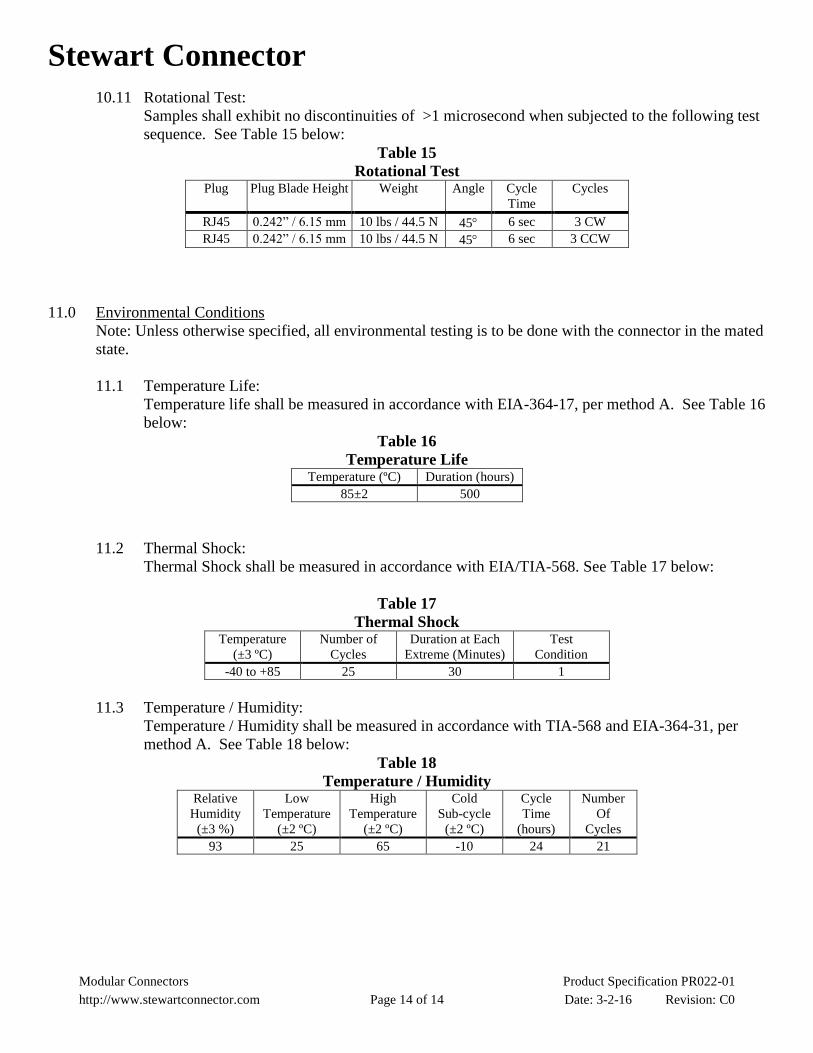
10.11 Rotational Test:
Samples shall exhibit no discontinuities of >1 microsecond when subjected to the following test
sequence. See Table 15 below:
Table 15
Rotational Test Plug Plug Blade Height Weight Angle Cycle
Time
Cycles
RJ45 0.242” / 6.15 mm 10 lbs / 44.5 N 45 6 sec 3 CW
RJ45 0.242” / 6.15 mm 10 lbs / 44.5 N 45 6 sec 3 CCW
11.0 Environmental Conditions
Note: Unless otherwise specified, all environmental testing is to be done with the connector in the mated
state.
11.1 Temperature Life:
Temperature life shall be measured in accordance with EIA-364-17, per method A. See Table 16
below:
Table 16
Temperature Life Temperature (ºC) Duration (hours)
85±2 500
11.2 Thermal Shock:
Thermal Shock shall be measured in accordance with EIA/TIA-568. See Table 17 below:
Table 17
Thermal Shock Temperature
(±3 ºC)
Number of
Cycles
Duration at Each
Extreme (Minutes)
Test
Condition
-40 to +85 25 30 1
11.3 Temperature / Humidity:
Temperature / Humidity shall be measured in accordance with TIA-568 and EIA-364-31, per
method A. See Table 18 below:
Table 18
Temperature / Humidity Relative
Humidity
(±3 %)
Low
Temperature
(±2 ºC)
High
Temperature
(±2 ºC)
Cold
Sub-cycle
(±2 ºC)
Cycle
Time
(hours)
Number
Of
Cycles
93 25 65 -10 24 21


![Specification - Digi-Key Sheets/Seoul Semiconductor/LY521... · Outline Dimensions 8. Packing 9. Soldering ... Optical Efficiency ŋelc - 50 - lm/W ... Dominant Wavelength[5] λd](https://static.fdocuments.us/doc/165x107/5b50389b7f8b9a396e8e045e/specification-digi-key-sheetsseoul-semiconductorly521-outline-dimensions.jpg)