Modular Control of a Rotary Inverted Pendulum System Control of a Rotary Inverted Pendulum System...
15
Paper ID #14582 Modular Control of a Rotary Inverted Pendulum System Dr. Xiumin Diao, Purdue University Xiumin Diao received his B.S. degree in Mechanical Design and Manufacturing from Yantai University, China, in 2000, M.S. degree in Measurement Technology and Automatic Device from Beijing University of Aeronautics and Astronautics, China, in 2003, and Ph.D. degree in Mechanical Engineering from New Mexico State University, Las Cruces, New Mexico, in 2007. He is currently an Assistant Professor in the School of Engineering Technology, Purdue University, West Lafayette, Indiana, United States. His re- search interest includes robotics (kinematics, dynamics, and control) and mechatronics (system modeling, simulation, design, analysis and control). In particular, he is interested in applying robotics technologies for rehabilitation and advanced manufacturing. Prior to joining Purdue University in 2014, Dr. Diao has been a senior electro-mechanical engineer with Xcision Medical System (Columbia, Maryland, United States) for more than five years, developing medical devices using robotics and automation technologies. c American Society for Engineering Education, 2016
Transcript of Modular Control of a Rotary Inverted Pendulum System Control of a Rotary Inverted Pendulum System...
Paper ID #14582
Modular Control of a Rotary Inverted Pendulum System
Dr. Xiumin Diao, Purdue University
Xiumin Diao received his B.S. degree in Mechanical Design and Manufacturing from Yantai University,China, in 2000, M.S. degree in Measurement Technology and Automatic Device from Beijing Universityof Aeronautics and Astronautics, China, in 2003, and Ph.D. degree in Mechanical Engineering from NewMexico State University, Las Cruces, New Mexico, in 2007. He is currently an Assistant Professor inthe School of Engineering Technology, Purdue University, West Lafayette, Indiana, United States. His re-search interest includes robotics (kinematics, dynamics, and control) and mechatronics (system modeling,simulation, design, analysis and control). In particular, he is interested in applying robotics technologiesfor rehabilitation and advanced manufacturing. Prior to joining Purdue University in 2014, Dr. Diao hasbeen a senior electro-mechanical engineer with Xcision Medical System (Columbia, Maryland, UnitedStates) for more than five years, developing medical devices using robotics and automation technologies.
c©American Society for Engineering Education, 2016
Modular Control of a Rotary Inverted Pendulum System School of Engineering Technology
Purdue University, West Lafayette, IN, USA Abstract
Control of an inverted pendulum is one of the most interesting and classical problems of control engineering. This paper addresses control design and implementation of a rotary inverted pendulum system. The system is developed for control instruction and laboratory exercise of feedback control for undergraduates. The control of the inverted pendulum system is to drive the pendulum from its hanging-down position to upright position and hold it there stably. The controller is decomposed into three sub-controllers: destabilizing controller, stabilizing controller, and mode controller. The destabilizing controller is employed to oscillates the pendulum back and forth until it builds up enough energy to break the hanging-down stable position and gets into a neighborhood of the upright unstable position. Then the stabilizing controller kicks in and maintains the pendulum in the upright unstable position with a capability of rejecting small disturbance to the pendulum. The mode controller is able to determine when to switch between the destabilizing controller and the stabilizing controller. The proposed control strategy of the inverted pendulum system is verified by both simulation and experiments. According to a qualitative student assessment survey, such a modularized control strategy helps students understand the control theory more effectively. I. Introduction
An inverted pendulum system is one of the most interesting and classical mechatronic systems
used for both research and education in control engineering. The aim of the control of an inverted pendulum system is to balance the pendulum using feedback control when the pendulum is in its upright unstable position. An inverted pendulum system has been known as an ideal demonstration in control laboratories when introducing basic feedback control concepts and theories1,2.
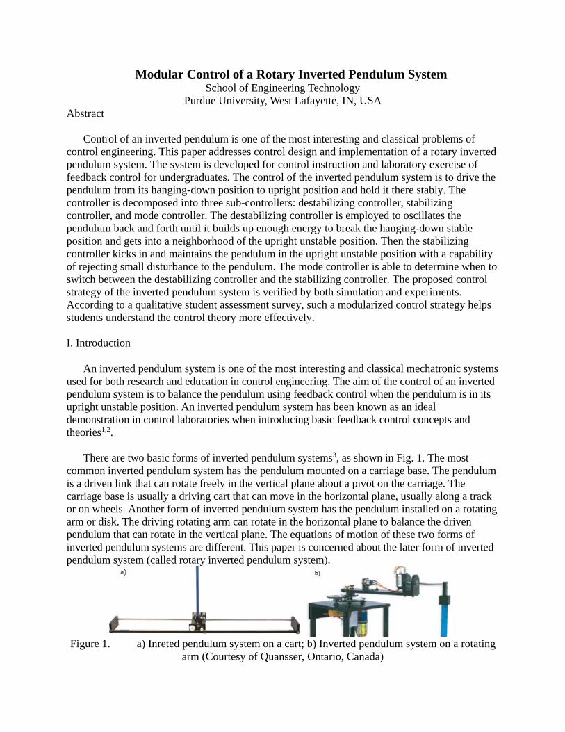
There are two basic forms of inverted pendulum systems3, as shown in Fig. 1. The most
common inverted pendulum system has the pendulum mounted on a carriage base. The pendulum is a driven link that can rotate freely in the vertical plane about a pivot on the carriage. The carriage base is usually a driving cart that can move in the horizontal plane, usually along a track or on wheels. Another form of inverted pendulum system has the pendulum installed on a rotating arm or disk. The driving rotating arm can rotate in the horizontal plane to balance the driven pendulum that can rotate in the vertical plane. The equations of motion of these two forms of inverted pendulum systems are different. This paper is concerned about the later form of inverted pendulum system (called rotary inverted pendulum system).
Figure 1. a) Inreted pendulum system on a cart; b) Inverted pendulum system on a rotating
arm (Courtesy of Quansser, Ontario, Canada)

As popular examples of unstable systems, various inverted pendulum systems have been used for research and education in control design for decades. Yamakita et al. demonstrated the power of modern control theory using an inverted pendulum system4. The inverted pendulum system was controlled in 3-D space by two robotic manipulators using visual feedback. An undergraduate laboratory for control system design was built with inverted pendulum apparatus for a feedback control course5. Such an inverted pendulum pivoting on a carriage moving on a straight rail is useful for stability analysis. Spong studied a two-degree-of-freedom planar robot (called Acrobot) with one actuator6. The swing-up control of the Acrobot was investigated using partial feedback linearization. An autonomous inverted pendulum cart was built and tested by White et al.3. The real-time control of the inverted pendulum cart was implemented using a battery-powered onboard processor that communicates with a laboratory host computer through Wi-Fi. Misawa et al. reported a low-cost rotational inverted pendulum system for demonstration of control theory7. Both linear quadratic controller and fuzzy controller were developed and their performance were compared. Reck and Sreenivas developed an affordable laboratory kit for multi-disciplinary controls education at both undergraduate and graduate levels8. With the kit, students can conduct labs of inverted pendulum control, DC motor control and so on. Sanchez et al. addressed an environment for teleoperation of real plant via Internet9. An inverted pendulum mounted on a linear motion cart was used to demonstrate the feasibility. Trajectory control of a mobile robot that is basically a wheeled inverted pendulum system was discussed by Ha and Yuta10. A gyro sensor was used to sense the inclination of the inverted pendulum and rotary encoders to detect wheels rotation. Such an concept has led to a commercial product, the Segway11.
This paper addresses control design and implementation of a rotary inverted pendulum system for an undergraduate automatic control class. The objective is to design a controller which is capable of driving the pendulum from its hanging-down stable position to a neighborhood of the upright unstable position and then holding it there stably. Although students are excited about the rotary inverted pendulum system, they usually do not even know where to start to achieve the control objective when facing the hardware at the beginning. The strategy of this lab instruction is to divide and conquer. The control objective is divided into multiple ones that are small enough such that students are confident and capable of achieving each of them. In this way, students go through small objectives one by one and eventually accomplish the final control objective. Specifically, students will 1) create a mathematical model of the rotary inverted pendulum system; 2) design a proper position controller; 3) design a destabilizing controller to oscillates the pendulum back and forth; 4) design a stabilizing controller to maintain the pendulum in the upright unstable position; and 5) design a mode controller to determine when to switch between the destabilizing controller and the stabilizing controller. Such a strategy not only makes the controller design straightforward for students, but also allows students to move forward step by step and eventually to accomplish the laboratory successfully. Student feedback is very positive according to a qualitative assessment survey.
II. Modeling of the Inverted Pendulum System
In the laboratory, students are expected to develop a controller for the rotary inverted
pendulum system from Quanser, as shown in Fig. 1(b). The system consists of a vertical pendulum, a horizontal rotating arm, a gear chain, and a servomotor which drives the pendulum through the gear transmission system. The rotating arm is mounted on the output gear of the gear

chain. A rotary encoder is attached to the arm shaft to measure the rotating angle of the arm. The pendulum is attached to a hinge located at the end of the rotating arm. The hinge is instrumented with a rotary encoder to measure the motion of the pendulum.
The inverted pendulum system (mechanical part only) shown in Fig. 1(b) is sketched in Fig. 2.
The equations of motion of the system can be obtained using the Lagrangian formulation. and are chosen as generalized coordinates to describe the inverted pendulum system. The pendulum is displaced with an angle of off the upright position while the rotating arm rotates an angle of . Assume the pendulum to be a lump mass at point B which is located at the geometric center of the pendulum. The xyz reference frame is fixed to the end of the arm at point A . Please refer to the Appendix for a complete list of symbols used in the mathematical modelling of the inverted pendulum system. According to the Lagrangian formulation, the nonlinear dynamics model of the system can be obtained as
Figure 2. Simplified model of the rotary inverted pendulum system
0)sin()cos(
)sin()cos( 2
dcb
fVebba m
where
m
gtgm
m
mgtgmeq
mggeq
R
KKf
R
KKKBemgLd
mLcmLrbJKmrJa
;;
3
4;;
2
222
Linearizing (1) under the assumption of 0 and 0 , one gets the linearized dynamics model of the inverted pendulum system as follows:
0
dcb
fVeba m
To verify the linear model against the nonlinear model, the linear model has been compared with the nonlinear model by simulation. The simulation results showed that when 15 , the linear model diverges from the nonlinear model by less than 0.8%. Therefore, the linear model can describe the motion of the inverted pendulum system accurately. The controller design will be based on the linear dynamics model.
A
x
z
y
O
B
Pendulum
arm
r
L
III. Controller Design The controller of the rotary inverted pendulum system is decomposed into three sub-
controllers, namely, destabilizing controller, stabilizing controller, and mode controller. The destabilizing controller, as the name implies, oscillates the pendulum back and forth until it builds up enough energy to break the hanging-down stable position and gets into the neighborhood of the upright unstable position. Then the stabilizing controller is turned on to stabilize the pendulum in its upright position. The mode controller determines when to switch between the destabilizing controller and the stabilizing controller.
The destabilizing controller essentially drives the rotating arm to get the pendulum away from
the hanging-down stable position. It simply makes sense that, by moving the rotating arm back and forth strongly enough, it can eventually swing up the pendulum. Hence, the first thing one needs to do is to design a position controller which can swing the rotating arm to achieve the destabilizing goal. The design of the destabilizing controller, the stabilizing controller, and the mode controller will be discussed in the next three sections.
A. Design of the position controller
The pendulum in the system has a length of (m) 335.02 L and its center of mass is located at its geometric center. Thus the natural frequency for small oscillation of the pendulum is given by
)(rad/ 628.64
3s
L
g
I
mgL
Ap
where AI is the mass moment of inertia of the pendulum about point A . To have the rotating arm to react to the pendulum’s movements quickly, the closed-loop response of the rotating arm should be considerably faster than the natural frequency of the pendulum. It would then be reasonable to design a closed-loop position controller for the rotating arm which has the following specifications
0.780 (rad/s), 512.26or %2%OS ,4 npn
where %OS is the maximum overshoot of the response of the rotating arm for a step input. For the rotating arm to track the desired position, a PD control law is designed as follows
vdpm KKV )(
This is a position control loop that controls the voltage applied to the motor so that tracks d .
Now one needs to determine vp KK and according the above defined specifications (5). By
obtaining the closed-loop transfer function of the input d and output and comparing it with the
standard transfer function of a second order system, the control gains can be solved as follows
612.19 ;585.0 pv KK
With these values of the control grains, the rotating arm is expected to track the desired position while meeting the required specifications (5).
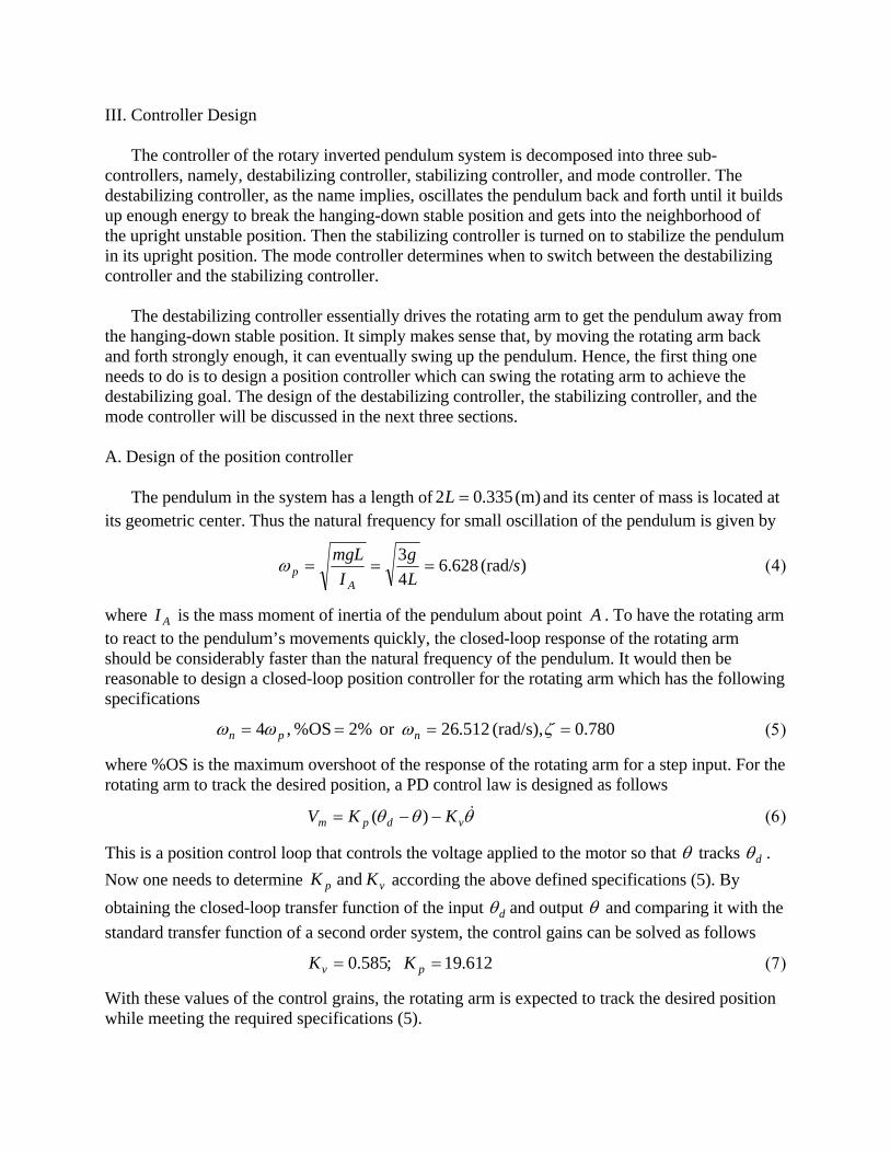
B. Simulation of the position controller
The Simulink diagram shown in Fig. 3 is created to check the performance of the designed position controller in (6). For a step input, the dynamic response of the inverted pendulum system is shown in Fig. 4. One can see that the response has a maximum overshoot of approximately 2% and the first peak is at 0.689 second. So the designed position controller in (6) meets the required specifications in (5).
Figure 3. Simulink diagram for verifying the position controller
Figure 4. Dynamic response of the inverted pendulum system to a step input
IV. Destabilizing Controller
When the pendulum is at its hanging-down stable position, one has to bring it up to the upright
position first before considering how to maintain it there. The destabilizing controller is designed for this purpose. Many schemes can be devised to achieve this. In this paper, the strategy to oscillate the pendulum back and forth until it builds up enough energy to break the hanging-down stable position and gets into the neighborhood of the upright but unstable position. In other words, a positive feedback controller is needed to destabilize the pendulum and eventually swing it up to the neighborhood of the upright position. Assume the position of the rotating arm can be commanded via d , then the positive feedback control law
DPd
0 0.1 0.2 0.3 0.4 0.5 0.6 0.7 0.8 0.9 10
5
10
15
20
25
Time (s)
Load
sha
ft p
ositi
on (
deg)
System reponse
Input command
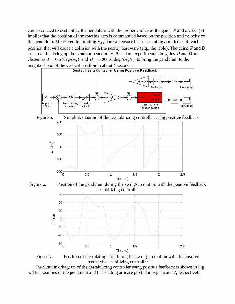
can be created to destabilize the pendulum with the proper choice of the gains DP and . Eq. (8) implies that the position of the rotating arm is commanded based on the position and velocity of the pendulum. Moreover, by limiting d , one can ensure that the rotating arm does not reach a
position that will cause a collision with the nearby hardware (e.g., the table). The gains DP and are crucial in bring up the pendulum smoothly. Based on experiments, the gains DP and are chosen as (deg/deg) 5.0P and )deg/(deg/s 00001.0D to bring the pendulum to the neighborhood of the vertical position in about 4 seconds.
Figure 5. Simulink diagram of the Destabilizing controller using positive feedback
Figure 6. Position of the pendulum during the swing-up motion with the positive feedback
destabilizing controller
Figure 7. Position of the rotating arm during the swing-up motion with the positive
feedback destabilizing controller The Simulink diagram of the destabilizing controller using positive feedback is shown in Fig.
5. The positions of the pendulum and the rotating arm are plotted in Figs. 6 and 7, respectively.
0 0.5 1 1.5 2 2.5-200
-100
0
100
200
Time (s)
(
deg)
0 0.5 1 1.5 2 2.5-30
-20
-10
0
10
20
30
Time (s)
(d
eg)
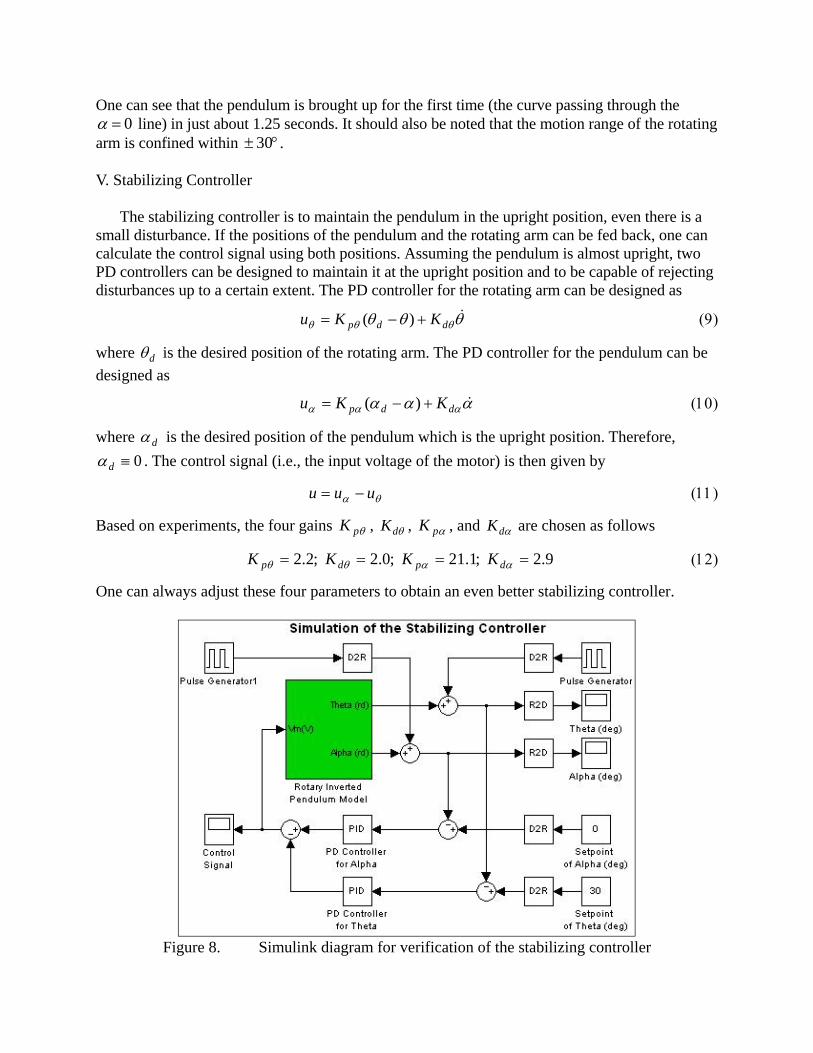
One can see that the pendulum is brought up for the first time (the curve passing through the 0 line) in just about 1.25 seconds. It should also be noted that the motion range of the rotating
arm is confined within 30 .
V. Stabilizing Controller The stabilizing controller is to maintain the pendulum in the upright position, even there is a
small disturbance. If the positions of the pendulum and the rotating arm can be fed back, one can calculate the control signal using both positions. Assuming the pendulum is almost upright, two PD controllers can be designed to maintain it at the upright position and to be capable of rejecting disturbances up to a certain extent. The PD controller for the rotating arm can be designed as
ddp KKu )(
where d is the desired position of the rotating arm. The PD controller for the pendulum can be
designed as
ddp KKu )(
where d is the desired position of the pendulum which is the upright position. Therefore,
0d . The control signal (i.e., the input voltage of the motor) is then given by
uuu
Based on experiments, the four gains pK , dK , pK , and dK are chosen as follows
9.2 ;1.21 ;0.2 ;2.2 dpdp KKKK
One can always adjust these four parameters to obtain an even better stabilizing controller.
Figure 8. Simulink diagram for verification of the stabilizing controller
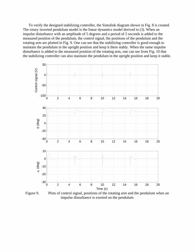
To verify the designed stabilizing controller, the Simulink diagram shown in Fig. 8 is created. The rotary inverted pendulum model is the linear dynamics model derived in (3). When an impulse disturbance with an amplitude of 5 degrees and a period of 5 seconds is added to the measured position of the pendulum, the control signal, the positions of the pendulum and the rotating arm are plotted in Fig. 9. One can see that the stabilizing controller is good enough to maintain the pendulum in the upright position and keep it there stably. When the same impulse disturbance is added to the measured position of the rotating arm, one can see from Fig. 10 that the stabilizing controller can also maintain the pendulum in the upright position and keep it stable.
Figure 9. Plots of control signal, positions of the rotating arm and the pendulum when an
impulse disturbance is exerted on the pendulum
0 2 4 6 8 10 12 14 16 18 20-100
-50
0
50
Con
trol
sig
nal (
V)
0 2 4 6 8 10 12 14 16 18 20-40
-20
0
20
40
(d
eg)
0 2 4 6 8 10 12 14 16 18 20-30
-20
-10
0
10
Time (s)
(
deg)
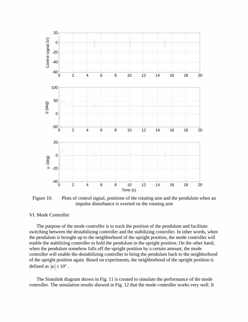
Figure 10. Plots of control signal, positions of the rotating arm and the pendulum when an
impulse disturbance is exerted on the rotating arm VI. Mode Controller
The purpose of the mode controller is to track the position of the pendulum and facilitate
switching between the destabilizing controller and the stabilizing controller. In other words, when the pendulum is brought up to the neighborhood of the upright position, the mode controller will enable the stabilizing controller to hold the pendulum in the upright position. On the other hand, when the pendulum somehow falls off the upright position by a certain amount, the mode controller will enable the destabilizing controller to bring the pendulum back to the neighborhood of the upright position again. Based on experiments, the neighborhood of the upright position is defined as 10 .
The Simulink diagram shown in Fig. 11 is created to simulate the performance of the mode
controller. The simulation results showed in Fig. 12 that the mode controller works very well. It
0 2 4 6 8 10 12 14 16 18 20-60
-40
-20
0
20
Con
trol
sig
nal (
V)
0 2 4 6 8 10 12 14 16 18 20-50
0
50
100
(d
eg)
0 2 4 6 8 10 12 14 16 18 20-40
-20
0
20
Time (s)
(
deg)
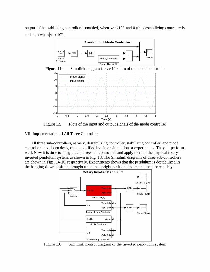
output 1 (the stabilizing controller is enabled) when 10 and 0 (the destabilizing controller is
enabled) when 10 .
Figure 11. Simulink diagram for verification of the model controller
Figure 12. Plots of the input and output signals of the mode controller
VII. Implementation of All Three Controllers
All three sub-controllers, namely, destabilizing controller, stabilizing controller, and mode
controller, have been designed and verified by either simulation or experiments. They all performs well. Now it is time to integrate all three sub-controllers and apply them to the physical rotary inverted pendulum system, as shown in Fig. 13. The Simulink diagrams of three sub-controllers are shown in Figs. 14-16, respectively. Experiments shows that the pendulum is destabilized in the hanging-down position, brought up to the upright position, and maintained there stably.
Figure 13. Simulink control diagram of the inverted pendulum system
0 0.5 1 1.5 2 2.5 3 3.5 4 4.5 5-15
-10
-5
0
5
10
15
Time (s)
Mode signal
Input signal
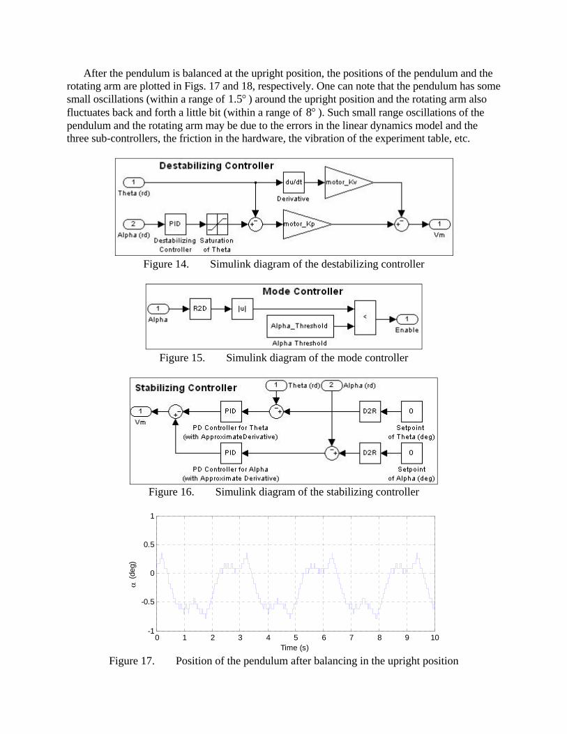
After the pendulum is balanced at the upright position, the positions of the pendulum and the rotating arm are plotted in Figs. 17 and 18, respectively. One can note that the pendulum has some small oscillations (within a range of 5.1 ) around the upright position and the rotating arm also fluctuates back and forth a little bit (within a range of 8 ). Such small range oscillations of the pendulum and the rotating arm may be due to the errors in the linear dynamics model and the three sub-controllers, the friction in the hardware, the vibration of the experiment table, etc.
Figure 14. Simulink diagram of the destabilizing controller
Figure 15. Simulink diagram of the mode controller
Figure 16. Simulink diagram of the stabilizing controller
Figure 17. Position of the pendulum after balancing in the upright position
0 1 2 3 4 5 6 7 8 9 10-1
-0.5
0
0.5
1
Time (s)
(
deg)
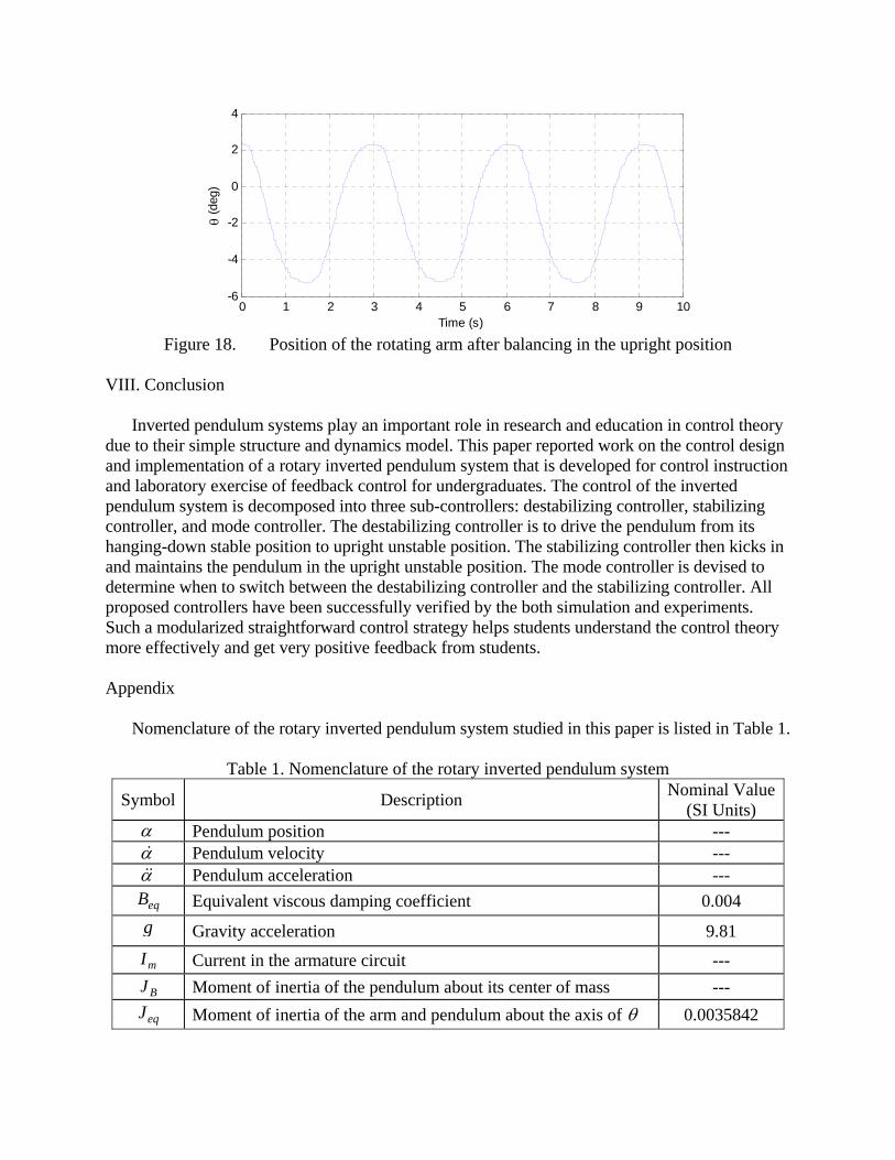
Figure 18. Position of the rotating arm after balancing in the upright position
VIII. Conclusion
Inverted pendulum systems play an important role in research and education in control theory
due to their simple structure and dynamics model. This paper reported work on the control design and implementation of a rotary inverted pendulum system that is developed for control instruction and laboratory exercise of feedback control for undergraduates. The control of the inverted pendulum system is decomposed into three sub-controllers: destabilizing controller, stabilizing controller, and mode controller. The destabilizing controller is to drive the pendulum from its hanging-down stable position to upright unstable position. The stabilizing controller then kicks in and maintains the pendulum in the upright unstable position. The mode controller is devised to determine when to switch between the destabilizing controller and the stabilizing controller. All proposed controllers have been successfully verified by the both simulation and experiments. Such a modularized straightforward control strategy helps students understand the control theory more effectively and get very positive feedback from students.
Appendix
Nomenclature of the rotary inverted pendulum system studied in this paper is listed in Table 1.
Table 1. Nomenclature of the rotary inverted pendulum system
Symbol Description Nominal Value
(SI Units) Pendulum position --- Pendulum velocity --- Pendulum acceleration ---
eqB Equivalent viscous damping coefficient 0.004
g Gravity acceleration 9.81
mI Current in the armature circuit ---
BJ Moment of inertia of the pendulum about its center of mass ---
eqJ Moment of inertia of the arm and pendulum about the axis of 0.0035842
0 1 2 3 4 5 6 7 8 9 10-6
-4
-2
0
2
4
Time (s)
(d
eg)

lJ Moment of inertia of the arm and pendulum about the axis of l ---
mJ Moment of inertia of the rotor of the motor 3.87e-7
gK SRV02 system gear ratio (motor -> load) 70
mK Back-emf constant 0.00767
tK Motor-torque constant 0.00767
L Half length of the pendulum 0.1675
mL Armature inductance --- m Mass of pendulum 0.125 r Rotating arm length 0.215
mR Armature resistance 2.6
lT Torque applied to the load ---
mT Torque generated by the motor ---
Load shaft position ---
Load shaft velocity ---
Load shaft acceleration ---
l Angular position of the arm ---
l Load shaft velocity ---
l Load shaft acceleration ---
m Motor shaft position ---
m Motor shaft velocity ---
m Motor shaft acceleration ---
emfV Motor back-emf voltage ---
mV Input voltage of the armature circuit ---
g Gearbox efficiency 0.9
m Motor efficiency 0.69 References 1 Mori, S., Nishihara, H. & Furuta, K. Control of unstable mechanical system Control of pendulum.
International Journal of Control 23, 673-692, doi:10.1080/00207177608922192 (1976). 2 Furuta, K., Kajiwara, H. & Kosuge, K. Digital control of a double inverted pendulum on an inclined rail.
International Journal of Control 32, 907-924, doi:10.1080/00207178008922898 (1980). 3 White, W. N., Wagner, J., Blankenau, B., Ziming, W. & Salazar, V. in Proceedings of the American Control
Conference (ACM). 5893-5898. 4 Yamakita, M., Hoshino, T. & Furuta, K. in Proceedings of the American Control Conference (ACM). 490-
494 vol.491. 5 Huang, G. M., Fu, L.-F. & Fleming, J. in American Control Conference, 1993. 2018-2023. 6 Spong, M. W. The swing up control problem for the Acrobot. IEEE Transactions on Control Systems 15, 49-
55, doi:10.1109/37.341864 (1995).

7 Misawa, E. A., Arrington, M. S. & Ledgerwood, T. D. in Proceedings of the American Control Conference (ACM). 29-33 vol.21.
8 Reck, R. & Sreenivas, R. in Proceedings of the ASME Dynamic Systems and Control Conference. 9 Sanchez, J., Dormido, S., Pastor, R. & Morilla, F. A Java/Matlab-based environment for remote control
system laboratories: illustrated with an inverted pendulum. IEEE Transactions on Education 47, 321-329, doi:10.1109/TE.2004.825525 (2004).
10 Ha, Y. & Yuta, S. in Proceedings of the IEEE/RSJ/GI International Conference on Intelligent Robots and Systems (IROS). 1875-1882 vol.1873.
11 Younis, W. & Abdelati, M. Design and Implementation of an Experimental Segway Model. Proceedings of AIP Conference 1107, 350-354, doi:doi:http://dx.doi.org/10.1063/1.3106501 (2009).


![Inverted Pendulum [Final]](https://static.fdocuments.us/doc/165x107/58904db31a28abcb668bcda8/inverted-pendulum-final.jpg)