MODU Nandgi e
60
Notices and General Information RULES FOR BUILDING AND CLASSING MOBILE OFFSHORE DRILLING UNITS 2008 NOTICES AND GENERAL INFORMATION American Bureau of Shipping Incorporated by Act of Legislature of the State of New York 1862 Copyright © 2008 American Bureau of Shipping ABS Plaza 16855 Northchase Drive Houston, TX 77060 USA
-
Upload
amanda-martinez -
Category
Documents
-
view
230 -
download
0
description
m.m.m
Transcript of MODU Nandgi e
N o t i c e s a n d G e n e r a l I n f o r m a t i o n
RULES FOR BUILDING AND CLASSING
MOBILE OFFSHORE DRILLING UNITS 2008
NOTICES AND GENERAL INFORMATION
American Bureau of Shipping Incorporated by Act of Legislature of the State of New York 1862
Copyright © 2008 American Bureau of Shipping ABS Plaza 16855 Northchase Drive Houston, TX 77060 USA

This Page Intentionally Left Blank
ABS RULES FOR BUILDING AND CLASSING MOBILE OFFSHORE DRILLING UNITS . 2008 iii
T a b l e o f C o n t e n t s
part Notices and General Information
CONTENTS Introduction....................................................................................................1
TABLE 1 Applicable Editions of Booklets Comprising 2008 Rules .............2 TABLE 2 Division and Numbering of Rules .................................................2
Change Notice (2008) ....................................................................................3
TABLE 3 Summary of Changes from the 2006 Rules .................................3 TABLE 4 Comparison of the Numbering System of the 2006 Rules vs.
2008 Rules ...................................................................................9

This Page Intentionally Left Blank
ABS RULES FOR BUILDING AND CLASSING MOBILE OFFSHORE DRILLING UNITS . 2008 1
Notices and General Information
Introduction
1. The year 2008 edition of the Rules for Building and Classing Mobile Offshore Drilling Units is a complete reprint of the 2006 edition, consisting of the seven (7) booklets as shown in Table 1. The Rules have been reorganized, and a new Part 5 for fire and safety measures and features has been added. The survey requirements in the former Part 5 are now in Part 6, along with requirements for surveys during construction and for testing and trials. The cross-reference table in Table 4 shows the relationship between the 2006 numbering and the 2008 numbering. The purpose of the generic title ABS Rules for Conditions of Classification – Offshore Units and Structures (Part 1) is to reflect the expanded contents of PART 1, as a result of including consolidated requirements for “Classification” applicable to all types of offshore units, pipelines, risers, and other offshore structures, as specified in the Foreword to Part 1.
With regard to Part 2, the purpose of the generic title ABS Rules for Materials and Welding is to emphasize the common applicability of the requirements to ABS-classed vessels, other marine structures and their associated machinery, and thereby make PART 2 more readily a common “PART” of various ABS Rules and Guides, as appropriate.
2. The numbering system applied in the Rules is shown in Table 2.
3. The primary changes from the 2006 edition of the Rules are identified and listed in Table 3. The effective date of the indicated Rule Changes is 1 January 2008, unless specifically indicated otherwise.
4. The effective date of each technical change since 1993 is shown in parenthesis at the end of the subsection/paragraph titles within the text of each Part. Unless a particular date and month are shown, the years in parentheses refer to the following effective dates:
(2000) and after 1 January 2000 (and subsequent years) (1996) 9 May 1996 (1999) 12 May 1999 (1995) 15 May 1995 (1998) 13 May 1998 (1994) 9 May 1994 (1997) 19 May 1997 (1993) 11 May 1993
5. Until the next edition of the Rules for Building and Classing Mobile Offshore Drilling Units is published, Rule Change Notices and/or Corrigenda, as necessary, will be published on the ABS website – www. eagle.org – only, and will be available free for downloading. It is not intended to publish hard copies of future Rule Change Notices and/or Corrigenda to existing Rules or Guides. The consolidated edition of the Rules for Building and Classing Mobile Offshore Drilling Units, which includes Rule Change Notices and/or Corrigenda using different colors for easy recognition will be published on the ABS website only when RCN and/or Corrigenda are issued.
6. The listing of CLASSIFICATION SYMBOLS AND NOTATIONS is available from the ABS website www.eagle.org/rules/downloads.html for download.
Notices and General Information
2 ABS RULES FOR BUILDING AND CLASSING MOBILE OFFSHORE DRILLING UNITS . 2008
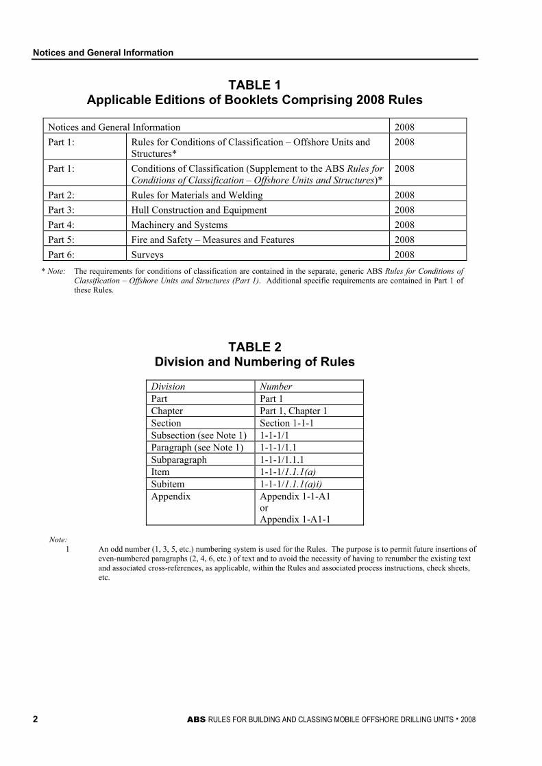
TABLE 1 Applicable Editions of Booklets Comprising 2008 Rules
Notices and General Information 2008 Part 1: Rules for Conditions of Classification – Offshore Units and
Structures* 2008
Part 1: Conditions of Classification (Supplement to the ABS Rules for Conditions of Classification – Offshore Units and Structures)*
2008
Part 2: Rules for Materials and Welding 2008 Part 3: Hull Construction and Equipment 2008 Part 4: Machinery and Systems 2008 Part 5: Fire and Safety – Measures and Features 2008 Part 6: Surveys 2008
* Note: The requirements for conditions of classification are contained in the separate, generic ABS Rules for Conditions of Classification – Offshore Units and Structures (Part 1). Additional specific requirements are contained in Part 1 of these Rules.
TABLE 2 Division and Numbering of Rules
Division Number Part Part 1 Chapter Part 1, Chapter 1 Section Section 1-1-1 Subsection (see Note 1) 1-1-1/1 Paragraph (see Note 1) 1-1-1/1.1 Subparagraph 1-1-1/1.1.1 Item 1-1-1/1.1.1(a) Subitem 1-1-1/1.1.1(a)i) Appendix Appendix 1-1-A1
or Appendix 1-A1-1
Note:
1 An odd number (1, 3, 5, etc.) numbering system is used for the Rules. The purpose is to permit future insertions of even-numbered paragraphs (2, 4, 6, etc.) of text and to avoid the necessity of having to renumber the existing text and associated cross-references, as applicable, within the Rules and associated process instructions, check sheets, etc.
Notices and General Information
ABS RULES FOR BUILDING AND CLASSING MOBILE OFFSHORE DRILLING UNITS . 2008 3
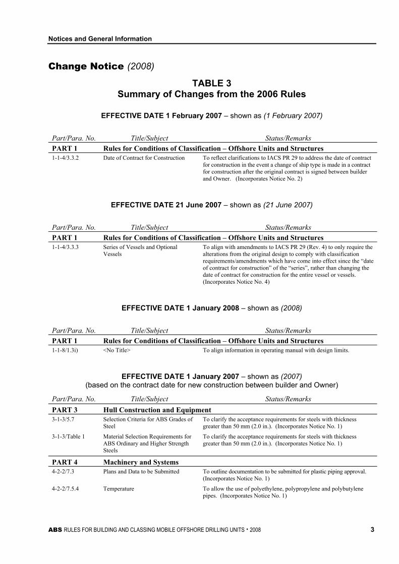
Change Notice (2008)
TABLE 3 Summary of Changes from the 2006 Rules
EFFECTIVE DATE 1 February 2007 – shown as (1 February 2007)
Part/Para. No. Title/Subject Status/Remarks PART 1 Rules for Conditions of Classification – Offshore Units and Structures 1-1-4/3.3.2 Date of Contract for Construction To reflect clarifications to IACS PR 29 to address the date of contract
for construction in the event a change of ship type is made in a contract for construction after the original contract is signed between builder and Owner. (Incorporates Notice No. 2)
EFFECTIVE DATE 21 June 2007 – shown as (21 June 2007)
Part/Para. No. Title/Subject Status/Remarks PART 1 Rules for Conditions of Classification – Offshore Units and Structures 1-1-4/3.3.3 Series of Vessels and Optional
Vessels To align with amendments to IACS PR 29 (Rev. 4) to only require the alterations from the original design to comply with classification requirements/amendments which have come into effect since the “date of contract for construction” of the “series”, rather than changing the date of contract for construction for the entire vessel or vessels. (Incorporates Notice No. 4)
EFFECTIVE DATE 1 January 2008 – shown as (2008)
Part/Para. No. Title/Subject Status/Remarks PART 1 Rules for Conditions of Classification – Offshore Units and Structures 1-1-8/1.3i) <No Title> To align information in operating manual with design limits.
EFFECTIVE DATE 1 January 2007 – shown as (2007) (based on the contract date for new construction between builder and Owner)
Part/Para. No. Title/Subject Status/Remarks PART 3 Hull Construction and Equipment 3-1-3/5.7 Selection Criteria for ABS Grades of
Steel To clarify the acceptance requirements for steels with thickness greater than 50 mm (2.0 in.). (Incorporates Notice No. 1)
3-1-3/Table 1 Material Selection Requirements for ABS Ordinary and Higher Strength Steels
To clarify the acceptance requirements for steels with thickness greater than 50 mm (2.0 in.). (Incorporates Notice No. 1)
PART 4 Machinery and Systems 4-2-2/7.3 Plans and Data to be Submitted To outline documentation to be submitted for plastic piping approval.
(Incorporates Notice No. 1)
4-2-2/7.5.4 Temperature To allow the use of polyethylene, polypropylene and polybutylene pipes. (Incorporates Notice No. 1)
Notices and General Information
4 ABS RULES FOR BUILDING AND CLASSING MOBILE OFFSHORE DRILLING UNITS . 2008
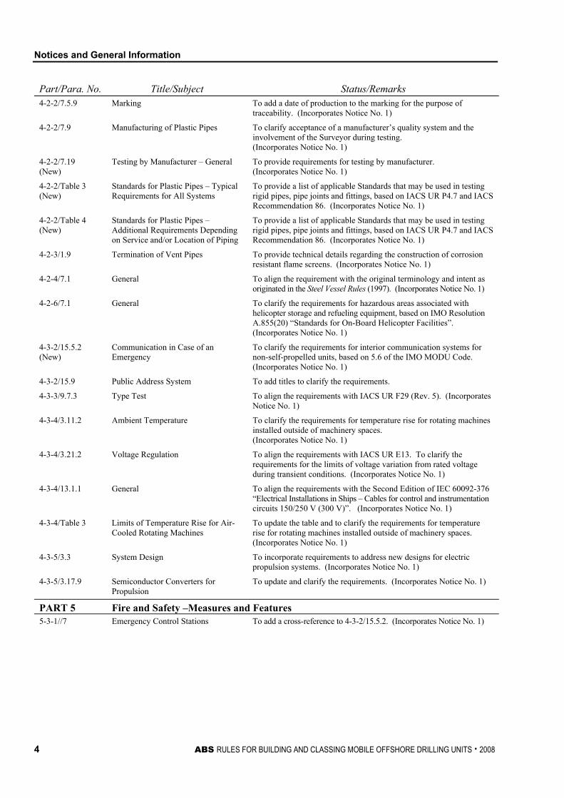
Part/Para. No. Title/Subject Status/Remarks 4-2-2/7.5.9 Marking To add a date of production to the marking for the purpose of
traceability. (Incorporates Notice No. 1)
4-2-2/7.9 Manufacturing of Plastic Pipes To clarify acceptance of a manufacturer’s quality system and the involvement of the Surveyor during testing. (Incorporates Notice No. 1)
4-2-2/7.19 (New)
Testing by Manufacturer – General To provide requirements for testing by manufacturer. (Incorporates Notice No. 1)
4-2-2/Table 3 (New)
Standards for Plastic Pipes – Typical Requirements for All Systems
To provide a list of applicable Standards that may be used in testing rigid pipes, pipe joints and fittings, based on IACS UR P4.7 and IACS Recommendation 86. (Incorporates Notice No. 1)
4-2-2/Table 4 (New)
Standards for Plastic Pipes – Additional Requirements Depending on Service and/or Location of Piping
To provide a list of applicable Standards that may be used in testing rigid pipes, pipe joints and fittings, based on IACS UR P4.7 and IACS Recommendation 86. (Incorporates Notice No. 1)
4-2-3/1.9 Termination of Vent Pipes To provide technical details regarding the construction of corrosion resistant flame screens. (Incorporates Notice No. 1)
4-2-4/7.1 General To align the requirement with the original terminology and intent as originated in the Steel Vessel Rules (1997). (Incorporates Notice No. 1)
4-2-6/7.1 General To clarify the requirements for hazardous areas associated with helicopter storage and refueling equipment, based on IMO Resolution A.855(20) “Standards for On-Board Helicopter Facilities”. (Incorporates Notice No. 1)
4-3-2/15.5.2 (New)
Communication in Case of an Emergency
To clarify the requirements for interior communication systems for non-self-propelled units, based on 5.6 of the IMO MODU Code. (Incorporates Notice No. 1)
4-3-2/15.9 Public Address System To add titles to clarify the requirements.
4-3-3/9.7.3 Type Test To align the requirements with IACS UR F29 (Rev. 5). (Incorporates Notice No. 1)
4-3-4/3.11.2 Ambient Temperature To clarify the requirements for temperature rise for rotating machines installed outside of machinery spaces. (Incorporates Notice No. 1)
4-3-4/3.21.2 Voltage Regulation To align the requirements with IACS UR E13. To clarify the requirements for the limits of voltage variation from rated voltage during transient conditions. (Incorporates Notice No. 1)
4-3-4/13.1.1 General To align the requirements with the Second Edition of IEC 60092-376 “Electrical Installations in Ships – Cables for control and instrumentation circuits 150/250 V (300 V)”. (Incorporates Notice No. 1)
4-3-4/Table 3 Limits of Temperature Rise for Air-Cooled Rotating Machines
To update the table and to clarify the requirements for temperature rise for rotating machines installed outside of machinery spaces. (Incorporates Notice No. 1)
4-3-5/3.3 System Design To incorporate requirements to address new designs for electric propulsion systems. (Incorporates Notice No. 1)
4-3-5/3.17.9 Semiconductor Converters for Propulsion
To update and clarify the requirements. (Incorporates Notice No. 1)
PART 5 Fire and Safety –Measures and Features 5-3-1//7 Emergency Control Stations To add a cross-reference to 4-3-2/15.5.2. (Incorporates Notice No. 1)
Notices and General Information
ABS RULES FOR BUILDING AND CLASSING MOBILE OFFSHORE DRILLING UNITS . 2008 5
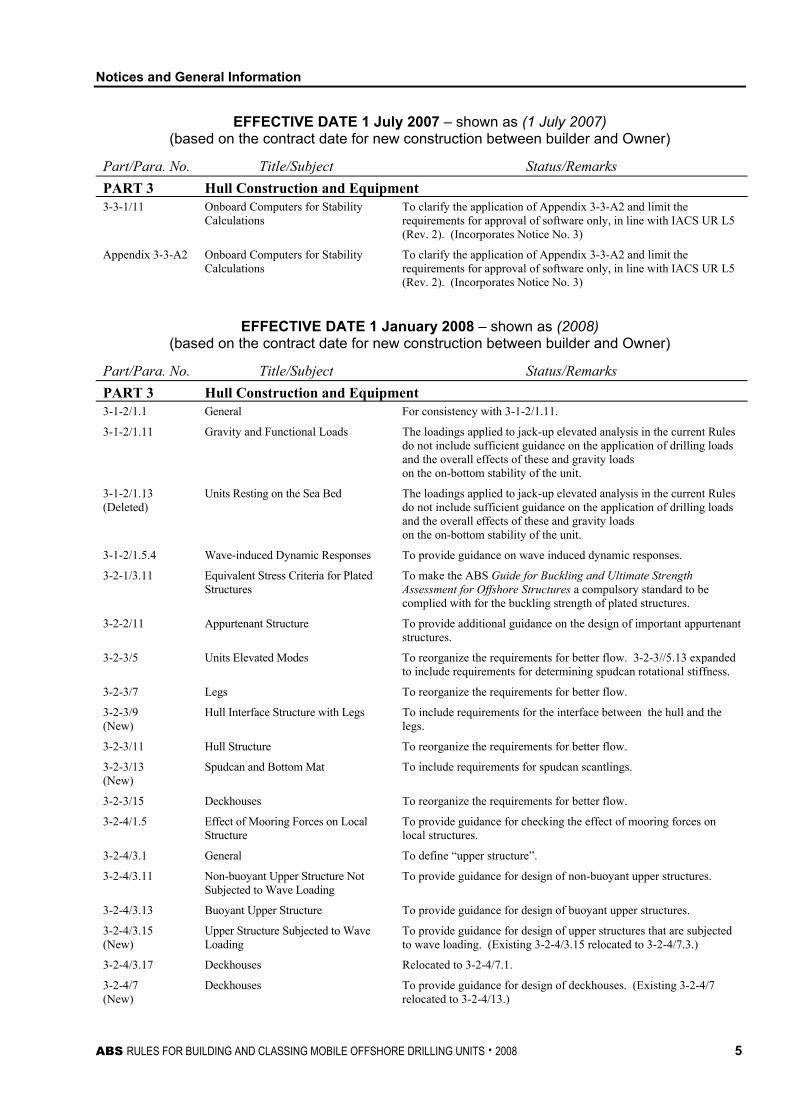
EFFECTIVE DATE 1 July 2007 – shown as (1 July 2007) (based on the contract date for new construction between builder and Owner)
Part/Para. No. Title/Subject Status/Remarks PART 3 Hull Construction and Equipment 3-3-1/11 Onboard Computers for Stability
Calculations To clarify the application of Appendix 3-3-A2 and limit the requirements for approval of software only, in line with IACS UR L5 (Rev. 2). (Incorporates Notice No. 3)
Appendix 3-3-A2 Onboard Computers for Stability Calculations
To clarify the application of Appendix 3-3-A2 and limit the requirements for approval of software only, in line with IACS UR L5 (Rev. 2). (Incorporates Notice No. 3)
EFFECTIVE DATE 1 January 2008 – shown as (2008) (based on the contract date for new construction between builder and Owner)
Part/Para. No. Title/Subject Status/Remarks PART 3 Hull Construction and Equipment 3-1-2/1.1 General For consistency with 3-1-2/1.11.
3-1-2/1.11 Gravity and Functional Loads The loadings applied to jack-up elevated analysis in the current Rules do not include sufficient guidance on the application of drilling loads and the overall effects of these and gravity loads on the on-bottom stability of the unit.
3-1-2/1.13 (Deleted)
Units Resting on the Sea Bed The loadings applied to jack-up elevated analysis in the current Rules do not include sufficient guidance on the application of drilling loads and the overall effects of these and gravity loads on the on-bottom stability of the unit.
3-1-2/1.5.4 Wave-induced Dynamic Responses To provide guidance on wave induced dynamic responses.
3-2-1/3.11 Equivalent Stress Criteria for Plated Structures
To make the ABS Guide for Buckling and Ultimate Strength Assessment for Offshore Structures a compulsory standard to be complied with for the buckling strength of plated structures.
3-2-2/11 Appurtenant Structure To provide additional guidance on the design of important appurtenant structures.
3-2-3/5 Units Elevated Modes To reorganize the requirements for better flow. 3-2-3//5.13 expanded to include requirements for determining spudcan rotational stiffness.
3-2-3/7 Legs To reorganize the requirements for better flow.
3-2-3/9 (New)
Hull Interface Structure with Legs To include requirements for the interface between the hull and the legs.
3-2-3/11 Hull Structure To reorganize the requirements for better flow.
3-2-3/13 (New)
Spudcan and Bottom Mat To include requirements for spudcan scantlings.
3-2-3/15 Deckhouses To reorganize the requirements for better flow.
3-2-4/1.5 Effect of Mooring Forces on Local Structure
To provide guidance for checking the effect of mooring forces on local structures.
3-2-4/3.1 General To define “upper structure”.
3-2-4/3.11 Non-buoyant Upper Structure Not Subjected to Wave Loading
To provide guidance for design of non-buoyant upper structures.
3-2-4/3.13 Buoyant Upper Structure To provide guidance for design of buoyant upper structures.
3-2-4/3.15 (New)
Upper Structure Subjected to Wave Loading
To provide guidance for design of upper structures that are subjected to wave loading. (Existing 3-2-4/3.15 relocated to 3-2-4/7.3.)
3-2-4/3.17 Deckhouses Relocated to 3-2-4/7.1.
3-2-4/7 (New)
Deckhouses To provide guidance for design of deckhouses. (Existing 3-2-4/7 relocated to 3-2-4/13.)
Notices and General Information
6 ABS RULES FOR BUILDING AND CLASSING MOBILE OFFSHORE DRILLING UNITS . 2008
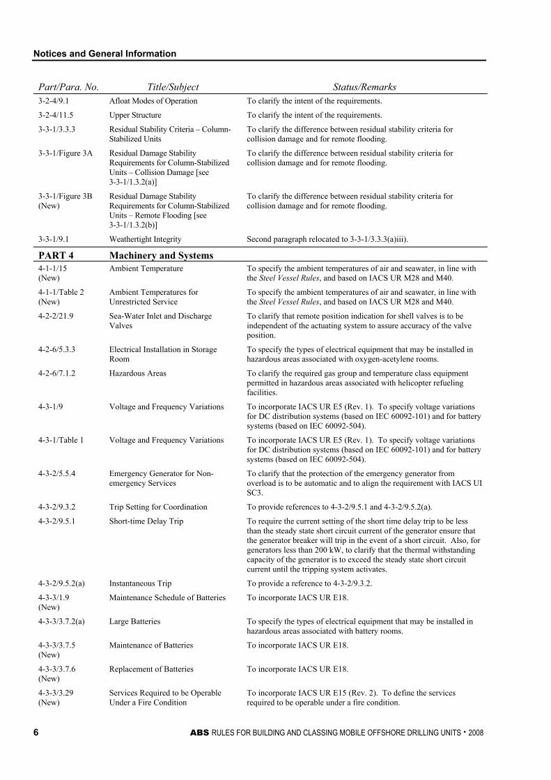
Part/Para. No. Title/Subject Status/Remarks 3-2-4/9.1 Afloat Modes of Operation To clarify the intent of the requirements.
3-2-4/11.5 Upper Structure To clarify the intent of the requirements.
3-3-1/3.3.3 Residual Stability Criteria – Column-Stabilized Units
To clarify the difference between residual stability criteria for collision damage and for remote flooding.
3-3-1/Figure 3A Residual Damage Stability Requirements for Column-Stabilized Units – Collision Damage [see 3-3-1/1.3.2(a)]
To clarify the difference between residual stability criteria for collision damage and for remote flooding.
3-3-1/Figure 3B (New)
Residual Damage Stability Requirements for Column-Stabilized Units – Remote Flooding [see 3-3-1/1.3.2(b)]
To clarify the difference between residual stability criteria for collision damage and for remote flooding.
3-3-1/9.1 Weathertight Integrity Second paragraph relocated to 3-3-1/3.3.3(a)iii).
PART 4 Machinery and Systems 4-1-1/15 (New)
Ambient Temperature To specify the ambient temperatures of air and seawater, in line with the Steel Vessel Rules, and based on IACS UR M28 and M40.
4-1-1/Table 2 (New)
Ambient Temperatures for Unrestricted Service
To specify the ambient temperatures of air and seawater, in line with the Steel Vessel Rules, and based on IACS UR M28 and M40.
4-2-2/21.9 Sea-Water Inlet and Discharge Valves
To clarify that remote position indication for shell valves is to be independent of the actuating system to assure accuracy of the valve position.
4-2-6/5.3.3 Electrical Installation in Storage Room
To specify the types of electrical equipment that may be installed in hazardous areas associated with oxygen-acetylene rooms.
4-2-6/7.1.2 Hazardous Areas To clarify the required gas group and temperature class equipment permitted in hazardous areas associated with helicopter refueling facilities.
4-3-1/9 Voltage and Frequency Variations To incorporate IACS UR E5 (Rev. 1). To specify voltage variations for DC distribution systems (based on IEC 60092-101) and for battery systems (based on IEC 60092-504).
4-3-1/Table 1 Voltage and Frequency Variations To incorporate IACS UR E5 (Rev. 1). To specify voltage variations for DC distribution systems (based on IEC 60092-101) and for battery systems (based on IEC 60092-504).
4-3-2/5.5.4 Emergency Generator for Non-emergency Services
To clarify that the protection of the emergency generator from overload is to be automatic and to align the requirement with IACS UI SC3.
4-3-2/9.3.2 Trip Setting for Coordination To provide references to 4-3-2/9.5.1 and 4-3-2/9.5.2(a).
4-3-2/9.5.1 Short-time Delay Trip To require the current setting of the short time delay trip to be less than the steady state short circuit current of the generator ensure that the generator breaker will trip in the event of a short circuit. Also, for generators less than 200 kW, to clarify that the thermal withstanding capacity of the generator is to exceed the steady state short circuit current until the tripping system activates.
4-3-2/9.5.2(a) Instantaneous Trip To provide a reference to 4-3-2/9.3.2.
4-3-3/1.9 (New)
Maintenance Schedule of Batteries To incorporate IACS UR E18.
4-3-3/3.7.2(a) Large Batteries To specify the types of electrical equipment that may be installed in hazardous areas associated with battery rooms.
4-3-3/3.7.5 (New)
Maintenance of Batteries To incorporate IACS UR E18.
4-3-3/3.7.6 (New)
Replacement of Batteries To incorporate IACS UR E18.
4-3-3/3.29 (New)
Services Required to be Operable Under a Fire Condition
To incorporate IACS UR E15 (Rev. 2). To define the services required to be operable under a fire condition.
Notices and General Information
ABS RULES FOR BUILDING AND CLASSING MOBILE OFFSHORE DRILLING UNITS . 2008 7
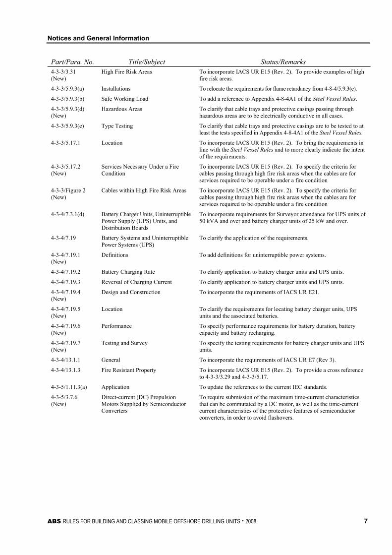
Part/Para. No. Title/Subject Status/Remarks 4-3-3/3.31 (New)
High Fire Risk Areas To incorporate IACS UR E15 (Rev. 2). To provide examples of high fire risk areas.
4-3-3/5.9.3(a) Installations To relocate the requirements for flame retardancy from 4-8-4/5.9.3(e).
4-3-3/5.9.3(b) Safe Working Load To add a reference to Appendix 4-8-4A1 of the Steel Vessel Rules.
4-3-3/5.9.3(d) (New)
Hazardous Areas To clarify that cable trays and protective casings passing through hazardous areas are to be electrically conductive in all cases.
4-3-3/5.9.3(e) Type Testing To clarify that cable trays and protective casings are to be tested to at least the tests specified in Appendix 4-8-4A1 of the Steel Vessel Rules.
4-3-3/5.17.1 Location To incorporate IACS UR E15 (Rev. 2). To bring the requirements in line with the Steel Vessel Rules and to more clearly indicate the intent of the requirements.
4-3-3/5.17.2 (New)
Services Necessary Under a Fire Condition
To incorporate IACS UR E15 (Rev. 2). To specify the criteria for cables passing through high fire risk areas when the cables are for services required to be operable under a fire condition
4-3-3/Figure 2 (New)
Cables within High Fire Risk Areas To incorporate IACS UR E15 (Rev. 2). To specify the criteria for cables passing through high fire risk areas when the cables are for services required to be operable under a fire condition
4-3-4/7.3.1(d) Battery Charger Units, Uninterruptible Power Supply (UPS) Units, and Distribution Boards
To incorporate requirements for Surveyor attendance for UPS units of 50 kVA and over and battery charger units of 25 kW and over.
4-3-4/7.19 Battery Systems and Uninterruptible Power Systems (UPS)
To clarify the application of the requirements.
4-3-4/7.19.1 (New)
Definitions To add definitions for uninterruptible power systems.
4-3-4/7.19.2 Battery Charging Rate To clarify application to battery charger units and UPS units.
4-3-4/7.19.3 Reversal of Charging Current To clarify application to battery charger units and UPS units.
4-3-4/7.19.4 (New)
Design and Construction To incorporate the requirements of IACS UR E21.
4-3-4/7.19.5 (New)
Location To clarify the requirements for locating battery charger units, UPS units and the associated batteries.
4-3-4/7.19.6 (New)
Performance To specify performance requirements for battery duration, battery capacity and battery recharging.
4-3-4/7.19.7 (New)
Testing and Survey To specify the testing requirements for battery charger units and UPS units.
4-3-4/13.1.1 General To incorporate the requirements of IACS UR E7 (Rev 3).
4-3-4/13.1.3 Fire Resistant Property To incorporate IACS UR E15 (Rev. 2). To provide a cross reference to 4-3-3/3.29 and 4-3-3/5.17.
4-3-5/1.11.3(a) Application To update the references to the current IEC standards.
4-3-5/3.7.6 (New)
Direct-current (DC) Propulsion Motors Supplied by Semiconductor Converters
To require submission of the maximum time-current characteristics that can be commutated by a DC motor, as well as the time-current current characteristics of the protective features of semiconductor converters, in order to avoid flashovers.
Notices and General Information
8 ABS RULES FOR BUILDING AND CLASSING MOBILE OFFSHORE DRILLING UNITS . 2008
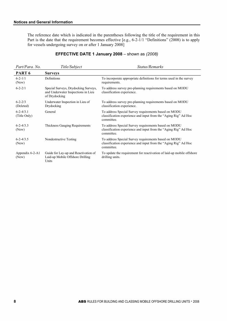
The reference date which is indicated in the parentheses following the title of the requirement in this Part is the date that the requirement becomes effective [e.g., 6-2-1/1 “Definitions” (2008) is to apply for vessels undergoing survey on or after 1 January 2008]
EFFECTIVE DATE 1 January 2008 – shown as (2008)
Part/Para. No. Title/Subject Status/Remarks PART 6 Surveys 6-2-1/1 (New)
Definitions To incorporate appropriate definitions for terms used in the survey requirements.
6-2-2/1 Special Surveys, Drydocking Surveys, and Underwater Inspections in Lieu of Drydocking
To address survey pre-planning requirements based on MODU classification experience.
6-2-2/3 (Deleted)
Underwater Inspection in Lieu of Drydocking
To address survey pre-planning requirements based on MODU classification experience.
6-2-4/3.1 (Title Only)
General To address Special Survey requirements based on MODU classification experience and input from the “Aging Rig” Ad Hoc committee.
6-2-4/3.3 (New)
Thickness Gauging Requirements To address Special Survey requirements based on MODU classification experience and input from the “Aging Rig” Ad Hoc committee.
6-2-4/3.5 (New)
Nondestructive Testing To address Special Survey requirements based on MODU classification experience and input from the “Aging Rig” Ad Hoc committee.
Appendix 6-2-A1 (New)
Guide for Lay-up and Reactivation of Laid-up Mobile Offshore Drilling Units
To update the requirement for reactivation of laid-up mobile offshore drilling units.
Notices and General Information
ABS RULES FOR BUILDING AND CLASSING MOBILE OFFSHORE DRILLING UNITS . 2008 9
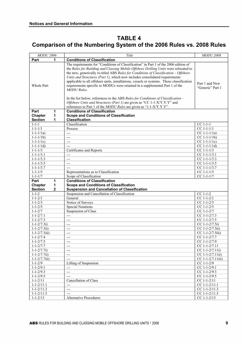
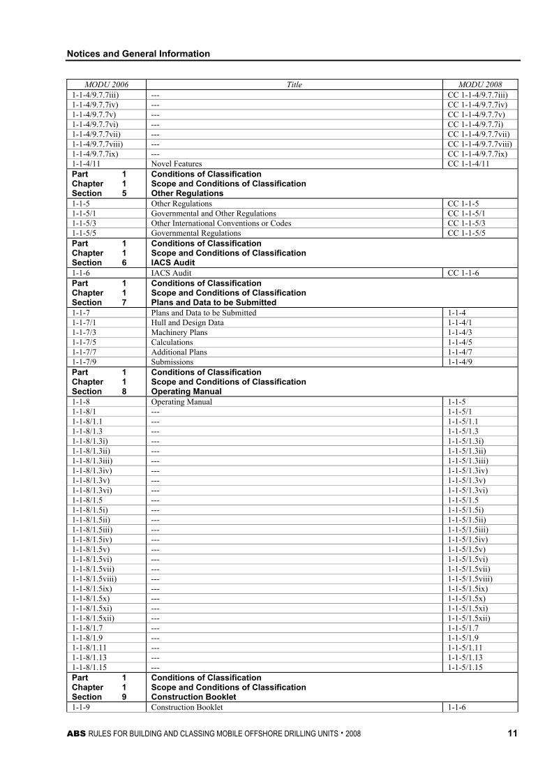
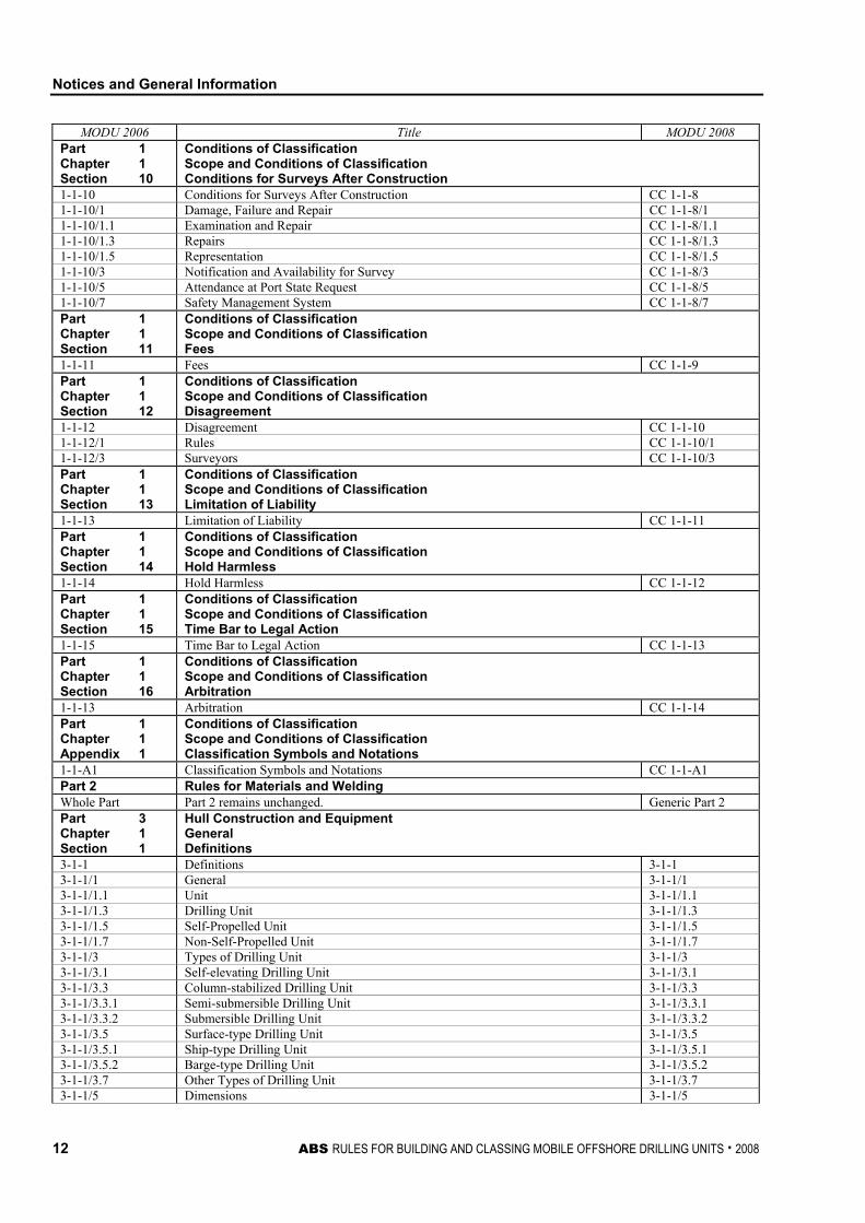
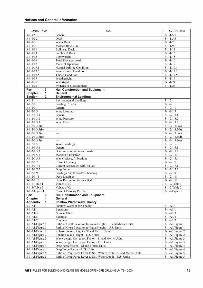
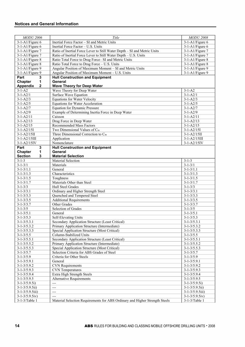
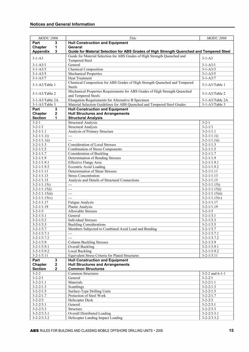
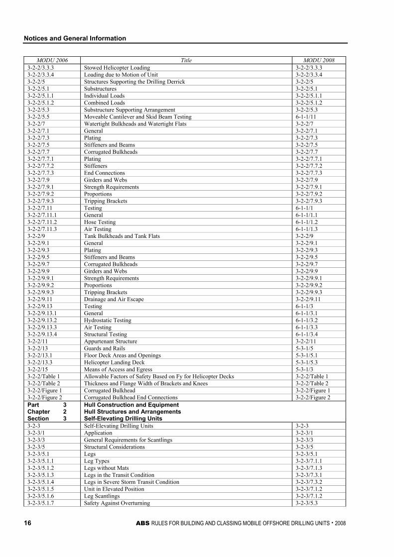
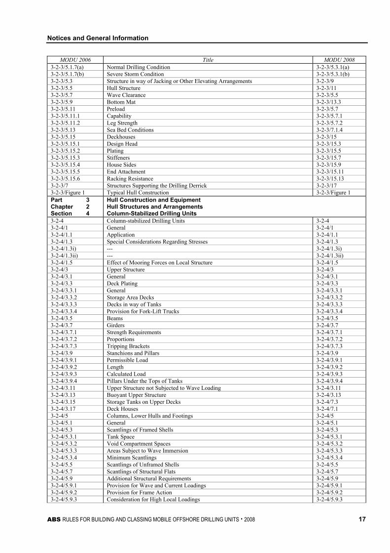
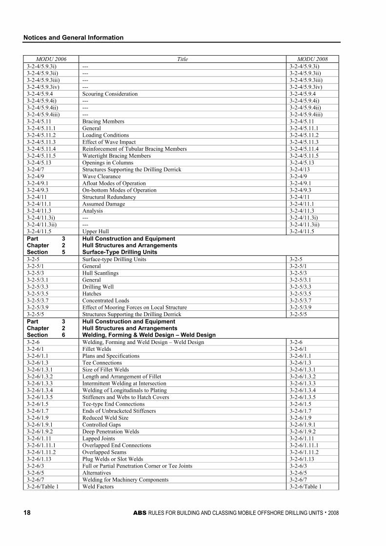
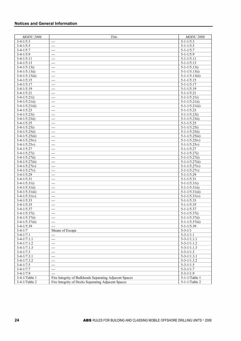
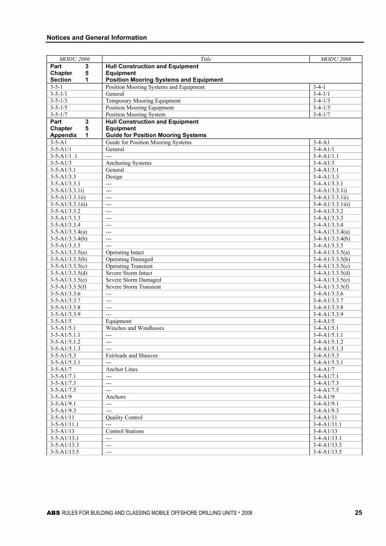
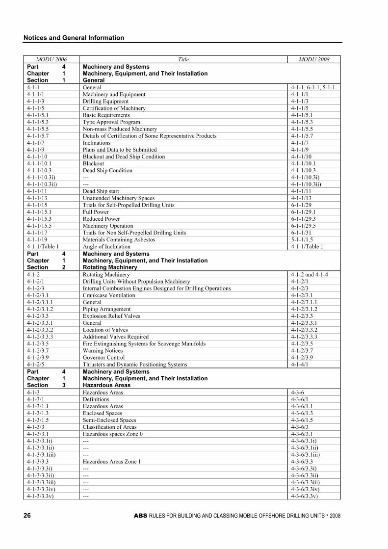
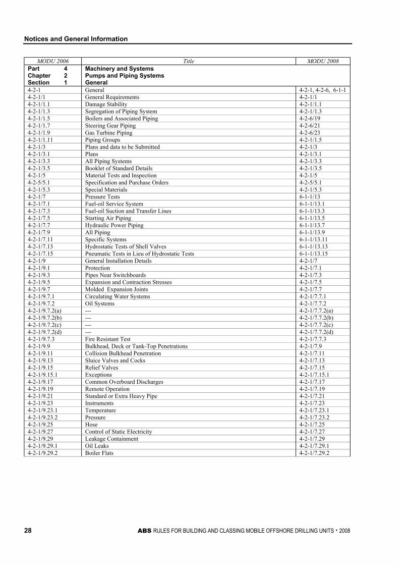
TABLE 4 Comparison of the Numbering System of the 2006 Rules vs. 2008 Rules
MODU 2006 Title MODU 2008 Part 1 Conditions of Classification
Whole Part
The requirements for “Conditions of Classification” in Part 1 of the 2006 edition of the Rules for Building and Classing Mobile Offshore Drilling Units were relocated to the new, generically re-titled ABS Rules for Conditions of Classification – Offshore Units and Structures (Part 1), which now includes consolidated requirements applicable to all offshore units, installations, vessels or systems. Those classification requirements specific to MODUs were retained in a supplemental Part 1 of the MODU Rules. In the list below, references to the ABS Rules for Conditions of Classification – Offshore Units and Structures (Part 1) are given as “CC 1-1-X/Y.Y.Y” and references to Part 1 of the MODU Rules are given as “1-1-X/Y.Y.Y”.
Part 1 and New “Generic” Part 1
Part 1 Chapter 1 Section 1
Conditions of Classification Scope and Conditions of Classification Classification
1-1-1 Classification CC 1-1-1 1-1-1/1 Process CC 1-1-1/1 1-1-1/1a) --- CC 1-1-1/1a) 1-1-1/1b) --- CC 1-1-1/1b) 1-1-1/1c) --- CC 1-1-1/1c) 1-1-1/1d) --- CC 1-1-1/1d) 1-1-1/3 Certificates and Reports CC 1-1-1/3 1-1-1/3.1 --- CC 1-1-1/3.1 1-1-1/3.3 --- CC 1-1-1/3.3 1-1-1/3.5 --- CC 1-1-1/3.5 1-1-1/3.7 --- CC 1-1-1/3.7 1-1-1/5 Representations as to Classification CC 1-1-1/5 1-1-1/7 Scope of Classification CC 1-1-1/7 Part 1 Chapter 1 Section 2
Conditions of Classification Scope and Conditions of Classification Suspension and Cancellation of Classification
1-1-2 Suspension and Cancellation of Classification CC 1-1-2 1-1-2/1 General CC 1-1-2/1 1-1-2/3 Notice of Surveys CC 1-1-2/3 1-1-2/5 Special Notations CC 1-1-2/5 1-1-2/7 Suspension of Class CC 1-1-2/7 1-1-2/7.1 --- CC 1-1-2/7.3 1-1-2/7.3 --- CC 1-1-2/7.5 1-1-2/7.3i) --- CC 1-1-2/7.5i) 1-1-2/7.3ii) --- CC 1-1-2/7.5ii) 1-1-2/7.3iii) --- CC 1-1-2/7.5iii) 1-1-2/7.4 --- CC 1-1-2/7.7 1-1-2/7.5 --- CC 1-1-2/7.9 1-1-2/7.7 --- CC 1-1-2/7.11 1-1-2/7.7i) --- CC 1-1-2/7.11i) 1-1-2/7.7ii) --- CC 1-1-2/7.11ii) 1-1-2/7.7iii) --- CC 1-1-2/7.11iii) 1-1-2/9 Lifting of Suspension CC 1-1-2/9 1-1-2/9.1 --- CC 1-1-2/9.1 1-1-2/9.3 --- CC 1-1-2/9.3 1-1-2/9.5 --- CC 1-1-2/9.5 1-1-2/11 Cancellation of Class CC 1-1-2/11 1-1-2/11.1 --- CC 1-1-2/11.1 1-1-2/11.3 --- CC 1-1-2/11.3 1-1-2/11.5 --- CC 1-1-2/11.5 1-1-2/13 Alternative Procedures CC 1-1-2/13
Notices and General Information
10 ABS RULES FOR BUILDING AND CLASSING MOBILE OFFSHORE DRILLING UNITS . 2008
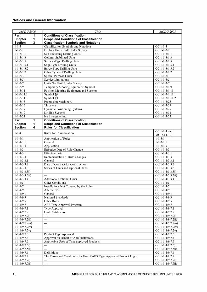
MODU 2006 Title MODU 2008 Part 1 Chapter 1 Section 3
Conditions of Classification Scope and Conditions of Classification Classification Symbols and Notations
1-1-3 Classification Symbols and Notations CC 1-1-3 1-1-3/1 Drilling Units Built Under Survey CC 1-1-3/1 1-1-3/1.1 Self-Elevating Drilling Units CC 1-1-3/1.1 1-1-3/1.3 Column-Stabilized Units CC 1-1-3/1.3 1-1-3/1.5 Surface-Type Drilling Units CC 1-1-3/1.5 1-1-3/1.5.1 Ship-Type Drilling Units CC 1-1-3/1.5.1 1-1-3/1.5.2 Barge-Type Drilling Units CC 1-1-3/1.5.2 1-1-3/1.7 Other Types of Drilling Units CC 1-1-3/1.7 1-1-3/3 Special Purpose Units CC 1-1-3/3 1-1-3/5 Service Limitations CC 1-1-3/5 1-1-3/7 Units Not Built Under Survey CC 1-1-3/7 1-1-3/9 Temporary Mooring Equipment Symbol CC 1-1-3/1.9 1-1-3/11 Position Mooring Equipment and Systems CC 1-1-3/1.11 1-1-3/11.1 Symbol  CC 1-1-3/1.11.1 1-1-3/11.3 Symbol à CC 1-1-3/1.11.2 1-1-3/13 Propulsion Machinery CC 1-1-3/25 1-1-3/15 Thrusters CC 1-1-3/27 1-1-3/17 Dynamic Positioning Systems CC 1-1-3/29 1-1-3/19 Drilling Systems CC 1-1-3/31 1-1-3/21 Ice Strengthening CC 1-1-3/33 Part 1 Chapter 1 Section 4
Conditions of Classification Scope and Conditions of Classification Rules for Classification
1-1-4 Rules for Classification CC 1-1-4 and MODU 1-1-3
1-1-4/1 Application of Rules 1-1-3/1 1-1-4/1.1 General 1-1-3/1.1 1-1-4/1.3 Application 1-1-3/1.3 1-1-4/3 Effective Date of Rule Change CC 1-1-4/3 1-1-4/3.1 Effective Date CC 1-1-4/3.1 1-1-4/3.3 Implementation of Rule Changes CC 1-1-4/3.3 1-1-4/3.3.1 General CC 1-1-4/3.3.1 1-1-4/3.3.2 Date of Contract for Construction CC 1-1-4/3.3.2 1-1-4/3.3.3 Series of Units and Optional Units CC 1-1-4/3.3.3 1-1-4/3.3.3i) --- CC 1-1-4/3.3.3i) 1-1-4/3.3.3ii) --- CC 1-1-4/3.3.3ii) 1-1-4/3.3.4 Additional Optional Units CC 1-1-4/3.3.4 1-1-4/5 Other Conditions CC 1-1-4/5 1-1-4/7 Installations Not Covered by the Rules CC 1-1-4/7 1-1-4/9 Alternatives CC 1-1-4/9 1-1-4/9.1 General CC 1-1-4/9.1 1-1-4/9.3 National Standards CC 1-1-4/9.3 1-1-4/9.5 Other Rules CC 1-1-4/9.5 1-1-4/9.7 ABS Type Approval Program CC 1-1-4/9.7 1-1-4/9.7.1 Type Approval CC 1-1-4/9.7.1 1-1-4/9.7.2 Unit Certification CC 1-1-4/9.7.2 1-1-4/9.7.2i) --- CC 1-1-4/9.7.2i) 1-1-4/9.7.2ii) --- CC 1-1-4/9.7.2ii) 1-1-4/9.7.2iii) --- CC 1-1-4/9.7.2iii) 1-1-4/9.7.2iv) --- CC 1-1-4/9.7.2iv) 1-1-4/9.7.2v) --- CC 1-1-4/9.7.2v) 1-1-4/9.7.3 Product Type Approval CC 1-1-4/9.7.3 1-1-4/9.7.4 Approval on Behalf of Administrations CC 1-1-4/9.7.4 1-1-4/9.7.5 Applicable Uses of Type approved Products CC 1-1-4/9.7.5 1-1-4/9.7.5i) --- CC 1-1-4/9.7.5) 1-1-4/9.7.5ii) --- CC 1-1-4/9.7.5ii) 1-1-4/9.7.6 Definitions CC 1-1-4/9.7.6 1-1-4/9.7.7 The Terms and Conditions for Use of ABS Type Approved Product Logo CC 1-1-4/9.7.7 1-1-4/9.7.7i) --- CC 1-1-4/9.7.7i) 1-1-4/9.7.7ii) --- CC 1-1-4/9.7.7ii)
Notices and General Information
ABS RULES FOR BUILDING AND CLASSING MOBILE OFFSHORE DRILLING UNITS . 2008 11
MODU 2006 Title MODU 2008 1-1-4/9.7.7iii) --- CC 1-1-4/9.7.7iii) 1-1-4/9.7.7iv) --- CC 1-1-4/9.7.7iv) 1-1-4/9.7.7v) --- CC 1-1-4/9.7.7v) 1-1-4/9.7.7vi) --- CC 1-1-4/9.7.7i) 1-1-4/9.7.7vii) --- CC 1-1-4/9.7.7vii) 1-1-4/9.7.7viii) --- CC 1-1-4/9.7.7viii) 1-1-4/9.7.7ix) --- CC 1-1-4/9.7.7ix) 1-1-4/11 Novel Features CC 1-1-4/11 Part 1 Chapter 1 Section 5
Conditions of Classification Scope and Conditions of Classification Other Regulations
1-1-5 Other Regulations CC 1-1-5 1-1-5/1 Governmental and Other Regulations CC 1-1-5/1 1-1-5/3 Other International Conventions or Codes CC 1-1-5/3 1-1-5/5 Governmental Regulations CC 1-1-5/5 Part 1 Chapter 1 Section 6
Conditions of Classification Scope and Conditions of Classification IACS Audit
1-1-6 IACS Audit CC 1-1-6 Part 1 Chapter 1 Section 7
Conditions of Classification Scope and Conditions of Classification Plans and Data to be Submitted
1-1-7 Plans and Data to be Submitted 1-1-4 1-1-7/1 Hull and Design Data 1-1-4/1 1-1-7/3 Machinery Plans 1-1-4/3 1-1-7/5 Calculations 1-1-4/5 1-1-7/7 Additional Plans 1-1-4/7 1-1-7/9 Submissions 1-1-4/9 Part 1 Chapter 1 Section 8
Conditions of Classification Scope and Conditions of Classification Operating Manual
1-1-8 Operating Manual 1-1-5 1-1-8/1 --- 1-1-5/1 1-1-8/1.1 --- 1-1-5/1.1 1-1-8/1.3 --- 1-1-5/1.3 1-1-8/1.3i) --- 1-1-5/1.3i) 1-1-8/1.3ii) --- 1-1-5/1.3ii) 1-1-8/1.3iii) --- 1-1-5/1.3iii) 1-1-8/1.3iv) --- 1-1-5/1.3iv) 1-1-8/1.3v) --- 1-1-5/1.3v) 1-1-8/1.3vi) --- 1-1-5/1.3vi) 1-1-8/1.5 --- 1-1-5/1.5 1-1-8/1.5i) --- 1-1-5/1.5i) 1-1-8/1.5ii) --- 1-1-5/1.5ii) 1-1-8/1.5iii) --- 1-1-5/1.5iii) 1-1-8/1.5iv) --- 1-1-5/1.5iv) 1-1-8/1.5v) --- 1-1-5/1.5v) 1-1-8/1.5vi) --- 1-1-5/1.5vi) 1-1-8/1.5vii) --- 1-1-5/1.5vii) 1-1-8/1.5viii) --- 1-1-5/1.5viii) 1-1-8/1.5ix) --- 1-1-5/1.5ix) 1-1-8/1.5x) --- 1-1-5/1.5x) 1-1-8/1.5xi) --- 1-1-5/1.5xi) 1-1-8/1.5xii) --- 1-1-5/1.5xii) 1-1-8/1.7 --- 1-1-5/1.7 1-1-8/1.9 --- 1-1-5/1.9 1-1-8/1.11 --- 1-1-5/1.11 1-1-8/1.13 --- 1-1-5/1.13 1-1-8/1.15 --- 1-1-5/1.15 Part 1 Chapter 1 Section 9
Conditions of Classification Scope and Conditions of Classification Construction Booklet
1-1-9 Construction Booklet 1-1-6
Notices and General Information
12 ABS RULES FOR BUILDING AND CLASSING MOBILE OFFSHORE DRILLING UNITS . 2008
MODU 2006 Title MODU 2008 Part 1 Chapter 1 Section 10
Conditions of Classification Scope and Conditions of Classification Conditions for Surveys After Construction
1-1-10 Conditions for Surveys After Construction CC 1-1-8 1-1-10/1 Damage, Failure and Repair CC 1-1-8/1 1-1-10/1.1 Examination and Repair CC 1-1-8/1.1 1-1-10/1.3 Repairs CC 1-1-8/1.3 1-1-10/1.5 Representation CC 1-1-8/1.5 1-1-10/3 Notification and Availability for Survey CC 1-1-8/3 1-1-10/5 Attendance at Port State Request CC 1-1-8/5 1-1-10/7 Safety Management System CC 1-1-8/7 Part 1 Chapter 1 Section 11
Conditions of Classification Scope and Conditions of Classification Fees
1-1-11 Fees CC 1-1-9 Part 1 Chapter 1 Section 12
Conditions of Classification Scope and Conditions of Classification Disagreement
1-1-12 Disagreement CC 1-1-10 1-1-12/1 Rules CC 1-1-10/1 1-1-12/3 Surveyors CC 1-1-10/3 Part 1 Chapter 1 Section 13
Conditions of Classification Scope and Conditions of Classification Limitation of Liability
1-1-13 Limitation of Liability CC 1-1-11 Part 1 Chapter 1 Section 14
Conditions of Classification Scope and Conditions of Classification Hold Harmless
1-1-14 Hold Harmless CC 1-1-12 Part 1 Chapter 1 Section 15
Conditions of Classification Scope and Conditions of Classification Time Bar to Legal Action
1-1-15 Time Bar to Legal Action CC 1-1-13 Part 1 Chapter 1 Section 16
Conditions of Classification Scope and Conditions of Classification Arbitration
1-1-13 Arbitration CC 1-1-14 Part 1 Chapter 1 Appendix 1
Conditions of Classification Scope and Conditions of Classification Classification Symbols and Notations
1-1-A1 Classification Symbols and Notations CC 1-1-A1 Part 2 Rules for Materials and Welding Whole Part Part 2 remains unchanged. Generic Part 2 Part 3 Chapter 1 Section 1
Hull Construction and Equipment General Definitions
3-1-1 Definitions 3-1-1 3-1-1/1 General 3-1-1/1 3-1-1/1.1 Unit 3-1-1/1.1 3-1-1/1.3 Drilling Unit 3-1-1/1.3 3-1-1/1.5 Self-Propelled Unit 3-1-1/1.5 3-1-1/1.7 Non-Self-Propelled Unit 3-1-1/1.7 3-1-1/3 Types of Drilling Unit 3-1-1/3 3-1-1/3.1 Self-elevating Drilling Unit 3-1-1/3.1 3-1-1/3.3 Column-stabilized Drilling Unit 3-1-1/3.3 3-1-1/3.3.1 Semi-submersible Drilling Unit 3-1-1/3.3.1 3-1-1/3.3.2 Submersible Drilling Unit 3-1-1/3.3.2 3-1-1/3.5 Surface-type Drilling Unit 3-1-1/3.5 3-1-1/3.5.1 Ship-type Drilling Unit 3-1-1/3.5.1 3-1-1/3.5.2 Barge-type Drilling Unit 3-1-1/3.5.2 3-1-1/3.7 Other Types of Drilling Unit 3-1-1/3.7 3-1-1/5 Dimensions 3-1-1/5
Notices and General Information
ABS RULES FOR BUILDING AND CLASSING MOBILE OFFSHORE DRILLING UNITS . 2008 13
MODU 2006 Title MODU 2008 3-1-1/5.1 General 3-1-1/5.1 3-1-1/5.3 Draft 3-1-1/5.3 3-1-1/7 Water Depth 3-1-1/7 3-1-1/9 Molded Base Line 3-1-1/9 3-1-1/11 Bulkhead Deck 3-1-1/11 3-1-1/13 Freeboard Deck 3-1-1/13 3-1-1/15 Lightweight 3-1-1/15 3-1-1/16 Total Elevated Load 3-1-1/16 3-1-1/17 Mode of Operation 3-1-1/17 3-1-1/17.1 Normal Drilling Condition 3-1-1/17.1 3-1-1/17.3 Severe Storm Condition 3-1-1/17.3 3-1-1/17.5 Transit Condition 3-1-1/17.5 3-1-1/19 Weathertight 3-1-1/19 3-1-1/21 Watertight 3-1-1/21 3-1-1/23 Systems of Measurement 3-1-1/23 Part 3 Chapter 1 Section 2
Hull Construction and Equipment General Environmental Loadings
3-1-2 Environmental Loadings 3-1-2 3-1-2/1 Loading Criteria 3-1-2/1 3-1-2/1.1 General 3-1-2/1.1 3-1-2/1.3 Wind Loadings 3-1-2/1.3 3-1-2/1.3.1 General 3-1-2/1.3.1 3-1-2/1.3.2 Wind Pressure 3-1-2/1.3.2 3-1-2/1.3.3 Wind Force 3-1-2/1.3.3 3-1-2/1.3.3(a) --- 3-1-2/1.3.3(a) 3-1-2/1.3.3(b) --- 3-1-2/1.3.3(b) 3-1-2/1.3.3(c) --- 3-1-2/1.3.3(c) 3-1-2/1.3.3(d) --- 3-1-2/1.3.3(d) 3-1-2/1.3.3(e) --- 3-1-2/1.3.3(e) 3-1-2/1.5 Wave Loadings 3-1-2/1.5 3-1-2/1.5.1 General 3-1-2/1.5.1 3-1-2/1.5.2 Determination of Wave Loads 3-1-2/1.5.2 3-1-2/1.5.3 Morison’s Equation 3-1-2/1.5.3 3-1-2/1.5.4 Wave Induced Vibrations 3-1-2/1.5.4 3-1-2/1.7 Current Loading 3-1-2/1.7 3-1-2/1.7.1 Current Associated with Waves 3-1-2/1.7.1 3-1-2/1.7.2 Drag Force 3-1-2/1.7.2 3-1-2/1.9 Loadings due to Vortex Shedding 3-1-2/1.9 3-1-2/1.11 Deck Loadings 3-1-2/1.11 3-1-2/1.13 Units Resting on the Sea Bed 3-1-2/1.13 3-1-2/Table 1 Values of Cs 3-1-2/Table 1 3-1-2/Table 2 Values of Ch 3-1-2/Table 2 3-1-2/Figure 1 Current Velocity Profile 3-1-2/Figure 1 Part 3 Chapter 1 Appendix 1
Hull Construction and Equipment General Shallow Water Wave Theory
3-1-A1 Shallow Water Wave Theory 3-1-A1 3-1-A1/1 Equations 3-1-A1/1 3-1-A1/3 Nomenclature 3-1-A1/3 3-1-A1/5 Example 3-1-A1/5 3-1-A1/7 Compute 3-1-A1/7 3-1-A1/Figure 1 Ratio of Crest Elevation to Wave Height – SI and Metric Units 3-1-A1/Figure 1 3-1-A1/Figure 1 Ratio of Crest Elevation to Wave Height – U.S. Units 3-1-A1/Figure 1 3-1-A1/Figure 2 Relative Wave Height – SI and Metric Units 3-1-A1/Figure 2 3-1-A1/Figure 2 Relative Wave Height – U.S. Units 3-1-A1/Figure 2 3-1-A1/Figure 3 Wave Length Correction Factor – SI and Metric Units 3-1-A1/Figure 3 3-1-A1/Figure 3 Wave Length Correction Factor – U.S. Units 3-1-A1/Figure 3 3-1-A1/Figure 4 Drag Force Factor – SI and Metric Units 3-1-A1/Figure 4 3-1-A1/Figure 4 Drag Force Factor – U.S. Units 3-1-A1/Figure 4 3-1-A1/Figure 5 Ratio of Drag Force Lever to Still Water Depth – SI and Metric Units 3-1-A1/Figure 5 3-1-A1/Figure 5 Ratio of Drag Force Lever to Still Water Depth – U.S. Units 3-1-A1/Figure 5
Notices and General Information
14 ABS RULES FOR BUILDING AND CLASSING MOBILE OFFSHORE DRILLING UNITS . 2008
MODU 2006 Title MODU 2008 3-1-A1/Figure 6 Inertial Force Factor – SI and Metric Units 3-1-A1/Figure 6 3-1-A1/Figure 6 Inertial Force Factor – U.S. Units 3-1-A1/Figure 6 3-1-A1/Figure 7 Ratio of Inertial Force Lever to Still Water Depth – SI and Metric Units 3-1-A1/Figure 7 3-1-A1/Figure 7 Ratio of Inertial Force Lever to Still Water Depth – U.S. Units 3-1-A1/Figure 7 3-1-A1/Figure 8 Ratio Total Force to Drag Force– SI and Metric Units 3-1-A1/Figure 8 3-1-A1/Figure 8 Ratio Total Force to Drag Force – U.S. Units 3-1-A1/Figure 8 3-1-A1/Figure 9 Angular Position of Maximum Moment – SI and Metric Units 3-1-A1/Figure 9 3-1-A1/Figure 9 Angular Position of Maximum Moment – U.S. Units 3-1-A1/Figure 9 Part 3 Chapter 1 Appendix 2
Hull Construction and Equipment General Wave Theory for Deep Water
3-1-A2 Wave Theory for Deep Water 3-1-A2 3-1-A2/1 Surface Wave Equation 3-1-A2/1 3-1-A2/3 Equations for Water Velocity 3-1-A2/3 3-1-A2/5 Equations for Water Acceleration 3-1-A2/5 3-1-A2/7 Equation for Dynamic Pressure 3-1-A2/7 3-1-A2/9 Example of Determining Inertia Force in Deep Water 3-1-A2/9 3-1-A2/11 Caisson 3-1-A2/11 3-1-A2/13 Drag Force in Deep Water 3-1-A2/13 3-1-A2/15 Recommended Mass Factors 3-1-A2/15 3-1-A2/15I Two Dimensional Values of Cm 3-1-A2/15I 3-1-A2/15II Three Dimensional Correction to Cm 3-1-A2/15II 3-1-A2/15III Application 3-1-A2/15III 3-1-A2/15IV Nomenclature 3-1-A2/15IV Part 3 Chapter 1 Section 3
Hull Construction and Equipment General Material Selection
3-1-3 Material Selection 3-1-3 3-1-3/1 Materials 3-1-3/1 3-1-3/1.1 General 3-1-3/1.1 3-1-3/1.3 Characteristics 3-1-3/1.3 3-1-3/1.5 Toughness 3-1-3/1.5 3-1-3/1.7 Materials Other than Steel 3-1-3/1.7 3-1-3/3 Hull Steel Grades 3-1-3/3 3-1-3/3.1 Ordinary and Higher Strength Steel 3-1-3/3.1 3-1-3/3.3 Quenched and Tempered Steel 3-1-3/3.3 3-1-3/3.5 Additional Requirements 3-1-3/3.5 3-1-3/3.7 Other Grades 3-1-3/3.7 3-1-3/5 Selection of Grades 3-1-3/5 3-1-3/5.1 General 3-1-3/5.1 3-1-3/5.3 Self-Elevating Units 3-1-3/5.3 3-1-3/5.3.1 Secondary Application Structure (Least Critical) 3-1-3/5.3.1 3-1-3/5.3.2 Primary Application Structure (Intermediate) 3-1-3/5.3.2 3-1-3/5.3.3 Special Application Structure (Most Critical) 3-1-3/5.3.3 3-1-3/5.5 Column-Stabilized Units 3-1-3/5.5 3-1-3/5.5.1 Secondary Application Structure (Least Critical) 3-1-3/5.5.1 3-1-3/5.5.2 Primary Application Structure (Intermediate) 3-1-3/5.5.2 3-1-3/5.5.3 Special Application Structure (Most Critical) 3-1-3/5.5.3 3-1-3/5.7 Selection Criteria for ABS Grades of Steel 3-1-3/5.7 3-1-3/5.9 Criteria for Other Steels 3-1-3/5.9 3-1-3/5.9.1 General 3-1-3/5.9.1 3-1-3/5.9.2 CVN Requirements 3-1-3/5.9.2 3-1-3/5.9.3 CVN Temperatures 3-1-3/5.9.3 3-1-3/5.9.4 Extra High Strength Steels 3-1-3/5.9.4 3-1-3/5.9.5 Alternative Requirements 3-1-3/5.9.5 3-1-3/5.9.5i) --- 3-1-3/5.9.5i) 3-1-3/5.9.5ii) --- 3-1-3/5.9.5ii) 3-1-3/5.9.5iii) --- 3-1-3/5.9.5iii) 3-1-3/5.9.5iv) --- 3-1-3/5.9.5iv) 3-1-3/Table 1 Material Selection Requirements for ABS Ordinary and Higher Strength Steels 3-1-3/Table 1
Notices and General Information
ABS RULES FOR BUILDING AND CLASSING MOBILE OFFSHORE DRILLING UNITS . 2008 15
MODU 2006 Title MODU 2008 Part 3 Chapter 1 Appendix 3
Hull Construction and Equipment General Guide for Material Selection for ABS Grades of High Strength Quenched and Tempered Steel
3-1-A3 Guide for Material Selection for ABS Grades of High Strength Quenched and Tempered Steel 3-1-A3
3-1-A3/1 General 3-1-A3/1 3-1-A3/3 Chemical Composition 3-1-A3/3 3-1-A3/5 Mechanical Properties 3-1-A3/5 3-1-A3/7 Heat Treatment 3-1-A3/7
3-1-A3/Table 1 Chemical Composition for ABS Grades of High Strength Quenched and Tempered Steels 3-1-A3/Table 1
3-1-A3/Table 2 Mechanical Properties Requirements for ABS Grades of High Strength Quenched and Tempered Steels 3-1-A3/Table 2
3-1-A3/Table 2A Elongation Requirements for Alternative B Specimen 3-1-A3/Table 2A 3-1-A3/Table 3 Material Selection Guidelines for ABS Quenched and Tempered Steel Grades 3-1-A3/Table 3 Part 3 Chapter 2 Section 1
Hull Construction and Equipment Hull Structures and Arrangements Structural Analysis
3-2-1 Structural Analysis 3-2-1 3-2-1/1 Structural Analysis 3-2-1/1 3-2-1/1.1 Analysis of Primary Structure 3-2-1/1.1 3-2-1/1.1i) --- 3-2-1/1.1i) 3-2-1/1.1ii) --- 3-2-1/1.1ii) 3-2-1/1.3 Consideration of Local Stresses 3-2-1/1.3 3-2-1/1.5 Combination of Stress Components 3-2-1/1.5 3-2-1/1.7 Consideration of Buckling 3-2-1/1.7 3-2-1/1.9 Determination of Bending Stresses 3-2-1/1.9 3-2-1/1.9.1 Effective Flange Area 3-2-1/1.9.1 3-2-1/1.9.2 Eccentric Axial Loading 3-2-1/1.9.2 3-2-1/1.11 Determination of Shear Stresses 3-2-1/1.11 3-2-1/1.13 Stress Concentration 3-2-1/1.13 3-2-1/1.15 Analysis and Details of Structural Connections 3-2-1/1.15 3-2-1/1.15i) --- 3-2-1/1.15i) 3-2-1/1.15ii) --- 3-2-1/1.15ii) 3-2-1/1.15iii) --- 3-2-1/1.15iii) 3-2-1/1.15iv) --- 3-2-1/1.15iv) 3-2-1/1.17 Fatigue Analysis 3-2-1/1.17 3-2-1/1.19 Plastic Analysis 3-2-1/1.19 3-2-1/3 Allowable Stresses 3-2-1/3 3-2-1/3.1 General 3-2-1/3.1 3-2-1/3.3 Individual Stresses 3-2-1/3.3 3-2-1/3.5 Buckling Considerations 3-2-1/3.5 3-2-1/3.7 Members Subjected to Combined Axial Load and Bending 3-2-1/3.7 3-2-1/3.7.1 --- 3-2-1/3.7.1 3-2-1/3.7.2 --- 3-2-1/3.7.2 3-2-1/3.9 Column Buckling Stresses 3-2-1/3.9 3-2-1/3.9.1 Overall Buckling 3-2-1/3.9.1 3-2-1/3.9.2 Local Buckling 3-2-1/3.9.2 3-2-1/3.11 Equivalent Stress Criteria for Plated Structures 3-2-1/3.11 Part 3 Chapter 2 Section 2
Hull Construction and Equipment Hull Structures and Arrangements Common Structures
3-2-2 Common Structures 3-2-2 and 6-1-1 3-2-2/1 General 3-2-2/1 3-2-2/1.1 Materials 3-2-2/1.1 3-2-2/1.3 Scantlings 3-2-2/1.3 3-2-2/1.5 Surface-Type Drilling Units 3-2-2/1.5 3-2-2/1.7 Protection of Steel Work 3-2-2/1.7 3-2-2/3 Helicopter Deck 3-2-2/3 3-2-2/3.1 General 3-2-2/3.1 3-2-2/3.3 Structure 3-2-2/3.3 3-2-2/3.3.1 Overall Distributed Loading 3-2-2/3.3.1 3-2-2/3.3.2 Helicopter Landing Impact Loading 3-2-2/3.3.2
Notices and General Information
16 ABS RULES FOR BUILDING AND CLASSING MOBILE OFFSHORE DRILLING UNITS . 2008
MODU 2006 Title MODU 2008 3-2-2/3.3.3 Stowed Helicopter Loading 3-2-2/3.3.3 3-2-2/3.3.4 Loading due to Motion of Unit 3-2-2/3.3.4 3-2-2/5 Structures Supporting the Drilling Derrick 3-2-2/5 3-2-2/5.1 Substructures 3-2-2/5.1 3-2-2/5.1.1 Individual Loads 3-2-2/5.1.1 3-2-2/5.1.2 Combined Loads 3-2-2/5.1.2 3-2-2/5.3 Substructure Supporting Arrangement 3-2-2/5.3 3-2-2/5.5 Moveable Cantilever and Skid Beam Testing 6-1-1/11 3-2-2/7 Watertight Bulkheads and Watertight Flats 3-2-2/7 3-2-2/7.1 General 3-2-2/7.1 3-2-2/7.3 Plating 3-2-2/7.3 3-2-2/7.5 Stiffeners and Beams 3-2-2/7.5 3-2-2/7.7 Corrugated Bulkheads 3-2-2/7.7 3-2-2/7.7.1 Plating 3-2-2/7.7.1 3-2-2/7.7.2 Stiffeners 3-2-2/7.7.2 3-2-2/7.7.3 End Connections 3-2-2/7.7.3 3-2-2/7.9 Girders and Webs 3-2-2/7.9 3-2-2/7.9.1 Strength Requirements 3-2-2/7.9.1 3-2-2/7.9.2 Proportions 3-2-2/7.9.2 3-2-2/7.9.3 Tripping Brackets 3-2-2/7.9.3 3-2-2/7.11 Testing 6-1-1/1 3-2-2/7.11.1 General 6-1-1/1.1 3-2-2/7.11.2 Hose Testing 6-1-1/1.2 3-2-2/7.11.3 Air Testing 6-1-1/1.3 3-2-2/9 Tank Bulkheads and Tank Flats 3-2-2/9 3-2-2/9.1 General 3-2-2/9.1 3-2-2/9.3 Plating 3-2-2/9.3 3-2-2/9.5 Stiffeners and Beams 3-2-2/9.5 3-2-2/9.7 Corrugated Bulkheads 3-2-2/9.7 3-2-2/9.9 Girders and Webs 3-2-2/9.9 3-2-2/9.9.1 Strength Requirements 3-2-2/9.9.1 3-2-2/9.9.2 Proportions 3-2-2/9.9.2 3-2-2/9.9.3 Tripping Brackets 3-2-2/9.9.3 3-2-2/9.11 Drainage and Air Escape 3-2-2/9.11 3-2-2/9.13 Testing 6-1-1/3 3-2-2/9.13.1 General 6-1-1/3.1 3-2-2/9.13.2 Hydrostatic Testing 6-1-1/3.2 3-2-2/9.13.3 Air Testing 6-1-1/3.3 3-2-2/9.13.4 Structural Testing 6-1-1/3.4 3-2-2/11 Appurtenant Structure 3-2-2/11 3-2-2/13 Guards and Rails 5-3-1/5 3-2-2/13.1 Floor Deck Areas and Openings 5-3-1/5.1 3-2-2/13.3 Helicopter Landing Deck 5-3-1/5.3 3-2-2/15 Means of Access and Egress 5-3-1/3 3-2-2/Table 1 Allowable Factors of Safety Based on Fy for Helicopter Decks 3-2-2/Table 1 3-2-2/Table 2 Thickness and Flange Width of Brackets and Knees 3-2-2/Table 2 3-2-2/Figure 1 Corrugated Bulkhead 3-2-2/Figure 1 3-2-2/Figure 2 Corrugated Bulkhead End Connections 3-2-2/Figure 2 Part 3 Chapter 2 Section 3
Hull Construction and Equipment Hull Structures and Arrangements Self-Elevating Drilling Units
3-2-3 Self-Elevating Drilling Units 3-2-3 3-2-3/1 Application 3-2-3/1 3-2-3/3 General Requirements for Scantlings 3-2-3/3 3-2-3/5 Structural Considerations 3-2-3/5 3-2-3/5.1 Legs 3-2-3/5.1 3-2-3/5.1.1 Leg Types 3-2-3/7.1.1 3-2-3/5.1.2 Legs without Mats 3-2-3/7.1.3 3-2-3/5.1.3 Legs in the Transit Condition 3-2-3/7.3.1 3-2-3/5.1.4 Legs in Severe Storm Transit Condition 3-2-3/7.3.2 3-2-3/5.1.5 Unit in Elevated Position 3-2-3/7.1.2 3-2-3/5.1.6 Leg Scantlings 3-2-3/7.1.2 3-2-3/5.1.7 Safety Against Overturning 3-2-3/5.3
Notices and General Information
ABS RULES FOR BUILDING AND CLASSING MOBILE OFFSHORE DRILLING UNITS . 2008 17
MODU 2006 Title MODU 2008 3-2-3/5.1.7(a) Normal Drilling Condition 3-2-3/5.3.1(a) 3-2-3/5.1.7(b) Severe Storm Condition 3-2-3/5.3.1(b) 3-2-3/5.3 Structure in way of Jacking or Other Elevating Arrangements 3-2-3/9 3-2-3/5.5 Hull Structure 3-2-3/11 3-2-3/5.7 Wave Clearance 3-2-3/5.5 3-2-3/5.9 Bottom Mat 3-2-3/13.3 3-2-3/5.11 Preload 3-2-3/5.7 3-2-3/5.11.1 Capability 3-2-3/5.7.1 3-2-3/5.11.2 Leg Strength 3-2-3/5.7.2 3-2-3/5.13 Sea Bed Conditions 3-2-3/7.1.4 3-2-3/5.15 Deckhouses 3-2-3/15 3-2-3/5.15.1 Design Head 3-2-3/15.3 3-2-3/5.15.2 Plating 3-2-3/15.5 3-2-3/5.15.3 Stiffeners 3-2-3/15.7 3-2-3/5.15.4 House Sides 3-2-3/15.9 3-2-3/5.15.5 End Attachment 3-2-3/15.11 3-2-3/5.15.6 Racking Resistance 3-2-3/15.13 3-2-3/7 Structures Supporting the Drilling Derrick 3-2-3/17 3-2-3/Figure 1 Typical Hull Construction 3-2-3/Figure 1 Part 3 Chapter 2 Section 4
Hull Construction and Equipment Hull Structures and Arrangements Column-Stabilized Drilling Units
3-2-4 Column-stabilized Drilling Units 3-2-4 3-2-4/1 General 3-2-4/1 3-2-4/1.1 Application 3-2-4/1.1 3-2-4/1.3 Special Considerations Regarding Stresses 3-2-4/1.3 3-2-4/1.3i) --- 3-2-4/1.3i) 3-2-4/1.3ii) --- 3-2-4/1.3ii) 3-2-4/1.5 Effect of Mooring Forces on Local Structure 3-2-4/1.5 3-2-4/3 Upper Structure 3-2-4/3 3-2-4/3.1 General 3-2-4/3.1 3-2-4/3.3 Deck Plating 3-2-4/3.3 3-2-4/3.3.1 General 3-2-4/3.3.1 3-2-4/3.3.2 Storage Area Decks 3-2-4/3.3.2 3-2-4/3.3.3 Decks in way of Tanks 3-2-4/3.3.3 3-2-4/3.3.4 Provision for Fork-Lift Trucks 3-2-4/3.3.4 3-2-4/3.5 Beams 3-2-4/3.5 3-2-4/3.7 Girders 3-2-4/3.7 3-2-4/3.7.1 Strength Requirements 3-2-4/3.7.1 3-2-4/3.7.2 Proportions 3-2-4/3.7.2 3-2-4/3.7.3 Tripping Brackets 3-2-4/3.7.3 3-2-4/3.9 Stanchions and Pillars 3-2-4/3.9 3-2-4/3.9.1 Permissible Load 3-2-4/3.9.1 3-2-4/3.9.2 Length 3-2-4/3.9.2 3-2-4/3.9.3 Calculated Load 3-2-4/3.9.3 3-2-4/3.9.4 Pillars Under the Tops of Tanks 3-2-4/3.9.4 3-2-4/3.11 Upper Structure not Subjected to Wave Loading 3-2-4/3.11 3-2-4/3.13 Buoyant Upper Structure 3-2-4/3.13 3-2-4/3.15 Storage Tanks on Upper Decks 3-2-4/7.3 3-2-4/3.17 Deck Houses 3-2-4/7.1 3-2-4/5 Columns, Lower Hulls and Footings 3-2-4/5 3-2-4/5.1 General 3-2-4/5.1 3-2-4/5.3 Scantlings of Framed Shells 3-2-4/5.3 3-2-4/5.3.1 Tank Space 3-2-4/5.3.1 3-2-4/5.3.2 Void Compartment Spaces 3-2-4/5.3.2 3-2-4/5.3.3 Areas Subject to Wave Immersion 3-2-4/5.3.3 3-2-4/5.3.4 Minimum Scantlings 3-2-4/5.3.4 3-2-4/5.5 Scantlings of Unframed Shells 3-2-4/5.5 3-2-4/5.7 Scantlings of Structural Flats 3-2-4/5.7 3-2-4/5.9 Additional Structural Requirements 3-2-4/5.9 3-2-4/5.9.1 Provision for Wave and Current Loadings 3-2-4/5.9.1 3-2-4/5.9.2 Provision for Frame Action 3-2-4/5.9.2 3-2-4/5.9.3 Consideration for High Local Loadings 3-2-4/5.9.3
Notices and General Information
18 ABS RULES FOR BUILDING AND CLASSING MOBILE OFFSHORE DRILLING UNITS . 2008
MODU 2006 Title MODU 2008 3-2-4/5.9.3i) --- 3-2-4/5.9.3i) 3-2-4/5.9.3ii) --- 3-2-4/5.9.3ii) 3-2-4/5.9.3iii) --- 3-2-4/5.9.3iii) 3-2-4/5.9.3iv) --- 3-2-4/5.9.3iv) 3-2-4/5.9.4 Scouring Consideration 3-2-4/5.9.4 3-2-4/5.9.4i) --- 3-2-4/5.9.4i) 3-2-4/5.9.4ii) --- 3-2-4/5.9.4ii) 3-2-4/5.9.4iii) --- 3-2-4/5.9.4iii) 3-2-4/5.11 Bracing Members 3-2-4/5.11 3-2-4/5.11.1 General 3-2-4/5.11.1 3-2-4/5.11.2 Loading Conditions 3-2-4/5.11.2 3-2-4/5.11.3 Effect of Wave Impact 3-2-4/5.11.3 3-2-4/5.11.4 Reinforcement of Tubular Bracing Members 3-2-4/5.11.4 3-2-4/5.11.5 Watertight Bracing Members 3-2-4/5.11.5 3-2-4/5.13 Openings in Columns 3-2-4/5.13 3-2-4/7 Structures Supporting the Drilling Derrick 3-2-4/13 3-2-4/9 Wave Clearance 3-2-4/9 3-2-4/9.1 Afloat Modes of Operation 3-2-4/9.1 3-2-4/9.3 On-bottom Modes of Operation 3-2-4/9.3 3-2-4/11 Structural Redundancy 3-2-4/11 3-2-4/11.1 Assumed Damage 3-2-4/11.1 3-2-4/11.3 Analysis 3-2-4/11.3 3-2-4/11.3i) --- 3-2-4/11.3i) 3-2-4/11.3ii) --- 3-2-4/11.3ii) 3-2-4/11.5 Upper Hull 3-2-4/11.5 Part 3 Chapter 2 Section 5
Hull Construction and Equipment Hull Structures and Arrangements Surface-Type Drilling Units
3-2-5 Surface-type Drilling Units 3-2-5 3-2-5/1 General 3-2-5/1 3-2-5/3 Hull Scantlings 3-2-5/3 3-2-5/3.1 General 3-2-5/3.1 3-2-5/3.3 Drilling Well 3-2-5/3.3 3-2-5/3.5 Hatches 3-2-5/3.5 3-2-5/3.7 Concentrated Loads 3-2-5/3.7 3-2-5/3.9 Effect of Mooring Forces on Local Structure 3-2-5/3.9 3-2-5/5 Structures Supporting the Drilling Derrick 3-2-5/5 Part 3 Chapter 2 Section 6
Hull Construction and Equipment Hull Structures and Arrangements Welding, Forming & Weld Design – Weld Design
3-2-6 Welding, Forming and Weld Design – Weld Design 3-2-6 3-2-6/1 Fillet Welds 3-2-6/1 3-2-6/1.1 Plans and Specifications 3-2-6/1.1 3-2-6/1.3 Tee Connections 3-2-6/1.3 3-2-6/1.3.1 Size of Fillet Welds 3-2-6/1.3.1 3-2-6/1.3.2 Length and Arrangement of Fillet 3-2-6/1.3.2 3-2-6/1.3.3 Intermittent Welding at Intersection 3-2-6/1.3.3 3-2-6/1.3.4 Welding of Longitudinals to Plating 3-2-6/1.3.4 3-2-6/1.3.5 Stiffeners and Webs to Hatch Covers 3-2-6/1.3.5 3-2-6/1.5 Tee-type End Connections 3-2-6/1.5 3-2-6/1.7 Ends of Unbracketed Stiffeners 3-2-6/1.7 3-2-6/1.9 Reduced Weld Size 3-2-6/1.9 3-2-6/1.9.1 Controlled Gaps 3-2-6/1.9.1 3-2-6/1.9.2 Deep Penetration Welds 3-2-6/1.9.2 3-2-6/1.11 Lapped Joints 3-2-6/1.11 3-2-6/1.11.1 Overlapped End Connections 3-2-6/1.11.1 3-2-6/1.11.2 Overlapped Seams 3-2-6/1.11.2 3-2-6/1.13 Plug Welds or Slot Welds 3-2-6/1.13 3-2-6/3 Full or Partial Penetration Corner or Tee Joints 3-2-6/3 3-2-6/5 Alternatives 3-2-6/5 3-2-6/7 Welding for Machinery Components 3-2-6/7 3-2-6/Table 1 Weld Factors 3-2-6/Table 1
Notices and General Information
ABS RULES FOR BUILDING AND CLASSING MOBILE OFFSHORE DRILLING UNITS . 2008 19
MODU 2006 Title MODU 2008 Part 3 Chapter 2 Section 7
Hull Construction and Equipment Hull Structures and Arrangements Welding, Forming & Weld Design – Production Welding
3-2-7 Welding, Forming and Weld Design – Production Welding 3-2-7 3-2-7/1 General 3-2-7/1 3-2-7/3 Thickness in Excess of 50 mm (2 in.) 3-2-7/3 3-2-7/5 Extent of Inspection of Welds 3-2-7/5 3-2-7/5.1 General 3-2-7/5.1 3-2-7/5.3 Extent and Method 3-2-7/5.3 3-2-7/5.3.1 Self-elevating Units 3-2-7/5.3.1 3-2-7/5.3.2 Column-stabilized Units 3-2-7/5.3.2 3-2-7/5.3.3 Nondestructive Inspection Plan 3-2-7/5.3.3 3-2-7/7 Acceptance Criteria 3-2-7/7 3-2-7/9 Fillet Welds 3-2-7/9 3-2-7/9.1 Workmanship 3-2-7/9.1 3-2-7/9.3 Special Precautions 3-2-7/9.3 Part 3 Chapter 2 Appendix 1
Hull Construction and Equipment Hull Structures and Arrangements Welding, Forming & Weld Design – Production Welding
3-2-A1 Guide for Strengthening of Mobile Offshore Drilling Units for Navigation in Ice 3-2-A1 3-2-A1/1 Application 3-2-A1/1 3-2-A1/1.1 Column Stabilized Unit 3-2-A1/1.1 3-2-A1/1.3 Units of Other Type 3-2-A1/1.3 3-2-A1/1.3.1 Surface Units 3-2-A1/1.3.1 3-2-A1/1.3.2 Self-elevating Units 3-2-A1/1.3.2 3-2-A1/1.5 Novel Features 3-2-A1/1.5 3-2-A1/3 Ice Class Selection 3-2-A1/3 3-2-A1/5 Ice Waterline 3-2-A1/5 3-2-A1/7 Clearance 3-2-A1/7 3-2-A1/9 Ice Belt 3-2-A1/9 3-2-A1/11 Design Ice Loads 3-2-A1/11 3-2-A1/11.1 Design Ice Pressure 3-2-A1/11.1 3-2-A1/11.3 Global Design Ice Load 3-2-A1/11.3 3-2-A1/13 Structural Evaluation 3-2-A1/13 3-2-A1/13.1 Global Evaluation 3-2-A1/13.1 3-2-A1/13.3 Local Scantlings 3-2-A1/13.3 3-2-A1/15 Other Requirements 3-2-A1/15 3-2-A1/Table 1 Guidance for Ice Class Selection of Column Stabilized Drilling Units 3-2-A1/Table 1
3-2-A1/Table 2 Definition of Ice Conditions of Broken First-year Ice Versus Concentration and Thickness 3-2-A1/Table 2
3-2-A1/Table 3 Ice Pressure Factors 3-2-A1/Table 3 3-2-A1/Figure 1 Ice Belt Areas 3-2-A1/Figure 1 Part 3 Chapter 3 Section 1
Hull Construction and Equipment Subdivision and Stability Stability and Watertight/Weathertight Integrity
3-3-1 Stability and Watertight/Weathertight Integrity 3-3-1 3-3-1/1 Stability 3-3-1/1 3-3-1/1.1 General 3-3-1/1.1 3-3-1/1.3 Stability Afloat 3-3-1/1.3 3-3-1/1.3.1 Intact Stability 3-3-1/1.3.1 3-3-1/1.3.2 Damage Stability 3-3-1/1.3.2 3-3-1/1.3.2(a) --- 3-3-1/1.3.2(a) 3-3-1/1.3.2(b) --- 3-3-1/1.3.2(b) 3-3-1/1.3.2(b)i) --- 3-3-1/1.3.2(b)i) 3-3-1/1.3.2(b)ii) --- 3-3-1/1.3.2(b)ii) 3-3-1/1.3.2(b)iii) --- 3-3-1/1.3.2(b)iii) 3-3-1/1.3.2(c) --- 3-3-1/1.3.2(c) 3-3-1/1.3.3 Alternatives for treatment of void spaces 3-3-1/1.3.3 3-3-1/1.3.3(a) --- 3-3-1/1.3.3(a) 3-3-1/1.3.3(b) --- 3-3-1/1.3.3(b) 3-3-1/1.5 Lightweight and Center of Gravity 3-3-1/1.5 3-3-1/3 Stability Criteria 3-3-1/3 3-3-1/3.1 General 3-3-1/3.1
Notices and General Information
20 ABS RULES FOR BUILDING AND CLASSING MOBILE OFFSHORE DRILLING UNITS . 2008
MODU 2006 Title MODU 2008 3-3-1/3.3 Righting Moment 3-3-1/3.3 3-3-1/3.3.1 Intact Stability Criteria 3-3-1/3.3.1 3-3-1/3.3.2 Damage Stability Criteria 3-3-1/3.3.2 3-3-1/3.3.3 Residual Stability Criteria – Column Stabilized Units 3-3-1/3.3.3 3-3-1/3.3.3(a) --- 3-3-1/3.3.3(a) 3-3-1/3.3.3(b) --- 3-3-1/3.3.3(b) 3-3-1/3.3.4 Residual Stability Criteria – Self-Elevating Units 3-3-1/3.3.4 3-3-1/3.5 Overturning Moment 3-3-1/3.5 3-3-1/3.7 Wind Tunnel Tests 3-3-1/3.7 3-3-1/3.9 Alternative Stability Criteria 3-3-1/3.9 3-3-1/3.9.1 General 3-3-1/3.9.1 3-3-1/3.9.2 Guidelines 3-3-1/3.9.2 3-3-1/3.9.2i) --- 3-3-1/3.9.2i) 3-3-1/3.9.2ii) --- 3-3-1/3.9.2ii) 3-3-1/3.9.2iii) --- 3-3-1/3.9.2iii) 3-3-1/3.9.2iv) --- 3-3-1/3.9.2iv) 3-3-1/3.9.2v) --- 3-3-1/3.9.2v) 3-3-1/3.9.2vi) --- 3-3-1/3.9.2vi) 3-3-1/3.9.3 Alternative Intact Stability Criteria 3-3-1/3.9.3 3-3-1/3.11 Units Resting on the Sea Bed 3-3-1/3.11 3-3-1/5 Load Line 3-3-1/5 3-3-1/7 Extent of Damage for Damage Stability Studies 3-3-1/7 3-3-1/7.1 Self-elevated Drilling Units 3-3-1/7.1 3-3-1/7.1i) --- 3-3-1/7.1i) 3-3-1/7.1ii) --- 3-3-1/7.1ii) 3-3-1/7.3 Column-stabilized Drilling Units 3-3-1/7.3 3-3-1/7.3i) --- 3-3-1/7.3i) 3-3-1/7.3ii) --- 3-3-1/7.3ii) 3-3-1/7.3iii) --- 3-3-1/7.3iii) 3-3-1/7.3iv) --- 3-3-1/7.3iv) 3-3-1/7.3v) --- 3-3-1/7.3v) 3-3-1/7.5 Surface-type Drilling Units 3-3-1/7.5 3-3-1/7.5i) --- 3-3-1/7.5i) 3-3-1/7.5ii) --- 3-3-1/7.5ii) 3-3-1/9 Watertight/Weathertight Integrity 3-3-1/9 3-3-1/9.1 Weathertight Integrity 3-3-1/9.1 3-3-1/9.3 Watertight Integrity 3-3-1/9.3 3-3-1/9.3.1 Internal Openings Used for Access While Afloat 3-3-1/9.3.1 3-3-1/9.3.1(a) --- 3-3-1/9.3.1(a) 3-3-1/9.3.1(b) --- 3-3-1/9.3.1(b) 3-3-1/9.3.1(c) --- 3-3-1/9.3.1(c) 3-3-1/9.3.2 Internal Openings Secured Closed While Afloat 3-3-1/9.3.2 3-3-1/9.3.2(a) --- 3-3-1/9.3.2(a) 3-3-1/9.3.2(b) --- 3-3-1/9.3.2(b) 3-3-1/9.3.2(c) --- 3-3-1/9.3.2(c) 3-3-1/9.3.2(d) --- 3-3-1/9.3.2(d) 3-3-1/9.3.3 External Openings Used While Afloat 3-3-1/9.3.3 3-3-1/9.3.3(a) --- 3-3-1/9.3.3(a) 3-3-1/9.3.3(b) --- 3-3-1/9.3.3(b) 3-3-1/9.3.3(c) --- 3-3-1/9.3.3(c) 3-3-1/9.3.4 External Openings Secured Closed While Afloat 3-3-1/9.3.4 3-3-1/9.5 Penetrations 3-3-1/9.3 3-3-1/11 Onboard Computers for Stability Calculations 3-3-1/11 3-3-1/Figure 1 Intact Stability Curve 3-3-1/Figure 1 3-3-1/Figure 2 Damage Stability Curve 3-3-1/Figure 2 3-3-1/Figure 3 Residual Damage Stability Requirements for Column Stabilized Units 3-3-1/Figure 3 3-3-1/Figure 4 Residual Damage Stability Requirements for Self-Elevating Units 3-3-1/Figure 4 3-3-1/Figure 5 Minimum Weathertight Integrity Requirements for Column Stabilized Units 3-3-1/Figure 5
Notices and General Information
ABS RULES FOR BUILDING AND CLASSING MOBILE OFFSHORE DRILLING UNITS . 2008 21
MODU 2006 Title MODU 2008 Part 3 Chapter 3 Appendix 1
Hull Construction and Equipment Subdivision and Stability Guide for the Application of Dynamic Response Based Intact Stability Criteria for Column-Stabilized Mobile Offshore Drilling Units
3-3-A1 Guide for the Application of Dynamic Response Based Intact Stability Criteria for Column-stabilized Mobile Offshore Drilling Units 3-3-A1
3-3-A1/1 Introduction 3-3-A1/1 3-3-A1/3 Definitions and Symbols 3-3-A1/3 3-3-A1/5 General 3-3-A1/5 3-3-A1/5.1 Scope 3-3-A1/5.1 3-3-A1/5.3 Conditions for Compliance 3-3-A1/5.3 3-3-A1/5.5 Dynamic-response-based Criteria 3-3-A1/5.5 3-3-A1/7 Dynamic-response-based Criteria 3-3-A1/7 3-3-A1/7.1 Criteria 3-3-A1/7.1 3-3-A1/7.1.1 Capsizing 3-3-A1/7.1.1 3-3-A1/7.1.2 Downflooding 3-3-A1/7.1.2 3-3-A17/7.3 Conditions of Assessment 3-3-A17/7.3 3-3-A17/7.3.1 3-3-A17/7.3.1 3-3-A17/7.3.2 3-3-A17/7.3.2 3-3-A17/7.3.3 3-3-A17/7.3.3 3-3-A17/7.3.4 3-3-A17/7.3.4 3-3-A1/9 Determination of Dynamic Response 3-3-A1/9 3-3-A1/9.1 Empirical Approximations 3-3-A1/9.1 3-3-A1/9.1.1 Maximum Dynamic Response Angle, θmax 3-3-A1/9.1.1 3-3-A1/9.1.2 Reduction in Downflooding Distance, RDFD 3-3-A1/9.1.2 3-3-A1/9.3 Application Limits of Empirical Approximations 3-3-A1/9.3 3-3-A1/9.3.1 Geometric Parameters 3-3-A1/9.3.1 3-3-A1/9.3.2 Operating Parameters 3-3-A1/9.3.2 3-3-A1/9.5 Direct Calculation 3-3-A1/9.5 3-3-A1/Figure 1 Capsize Criteria Format 3-3-A1/Figure 1 3-3-A1/Figure 2 Downflooding Criteria Concepts 3-3-A1/Figure 2 Part 3 Chapter 3 Appendix 1a
Hull Construction and Equipment Subdivision and Stability Sample Calculations
3-3-A1a Sample Calculations 3-3-A1a 3-3-A1a/1 Capsize Criteria Assessment (Metric Units) 3-3-A1a/1 3-3-A1a/3 Downflooding Criteria Assessment (Metric Units) 3-3-A1a/3 Part 3 Chapter 3 Appendix 1b
Hull Construction and Equipment Subdivision and Stability Direct Analysis of Dynamic Motion Responses
3-3-A1b Direct Analysis of Dynamic Motion Responses 3-3-A1b 3-3-A1b/1 General 3-3-A1b/1 3-3-A1b/3 Analysis Methods and Theoretical Background 3-3-A1b/3 3-3-A1b/5 Analysis Conditions 3-3-A1b/5 3-3-A1b/5.1 Environmental Conditions 3-3-A1b/5.1 3-3-A1b/5.3 Heading 3-3-A1b/5.3 3-3-A1b/5.5 Hydrodynamic Coefficients 3-3-A1b/5.5 3-3-A1b/5.7 Radii of Gyration 3-3-A1b/5.7 3-3-A1b/5.9 Mooring Arrangement 3-3-A1b/5.9 3-3-A1b/7 Representation of Environment 3-3-A1b/7 3-3-A1b/7.1 Wind Loads 3-3-A1b/7.1 3-3-A1b/7.3 Wave Loads 3-3-A1b/7.3 3-3-A1b/7.5 Current Effects 3-3-A1b/7.5 3-3-A1b/9 Results of Analyses and Format 3-3-A1b/9 3-3-A1b/9i) --- 3-3-A1b/9i) 3-3-A1b/9ii) --- 3-3-A1b/9ii) 3-3-A1b/9iii) --- 3-3-A1b/9iii) 3-3-A1b/11 Model Tests 3-3-A1b/11 3-3-A1b/11i) --- 3-3-A1b/11i) 3-3-A1b/11ii) --- 3-3-A1b/11ii) 3-3-A1b/11iii) --- 3-3-A1b/11iii) 3-3-A1b/11iv) --- 3-3-A1b/11iv)

Notices and General Information
22 ABS RULES FOR BUILDING AND CLASSING MOBILE OFFSHORE DRILLING UNITS . 2008
MODU 2006 Title MODU 2008 Part 3 Chapter 3 Appendix 1c
Hull Construction and Equipment Subdivision and Stability Environmental Conditions and Representations
3-3-A1c Environmental Conditions and Representations 3-3-A1c 3-3-A1c/1 General 3-3-A1c/1 3-3-A1c/3 ABS Average Measured Wind Spectrum 3-3-A1c/3 3-3-A1c/5 Wave Spectra 3-3-A1c/5 3-3-A1c/5.1 Fetch-limited Regions 3-3-A1c/5.1 3-3-A1c/5.3 Open Seas 3-3-A1c/5.3 3-3-A1c/Figure 1 Joint Probabilities of Occurrence of Wind Speed and Wave Height 3-3-A1c/Figure 1 Part 3 Chapter 3 Appendix 2
Hull Construction and Equipment Subdivision and Stability Response Analysis – Guide for Selecting Design Waves for Structural Analysis of Column-Stabilized Drilling Units (Twin-Hull Semi-Submersible)
3-3-A2 Response Analysis – Guide for Selecting Design Waves for Structural Analysis of Column-Stabilized Drilling Units (Twin-hull Semi-Submersible) 3-2-A2
3-3-A2/1 General 3-2-A2/1 3-3-A2/1.1 Introduction 3-2-A2/1.1 3-3-A2/3 Global Hydrodynamic Load Characteristics 3-2-A2/3 3-3-A2/3.1 General 3-2-A2/3.1 3-3-A2/3.1i) --- 3-2-A2/3.1i) 3-3-A2/3.1ii) --- 3-2-A2/3.1ii) 3-3-A2/3.1iii) --- 3-2-A2/3.1iii) 3-3-A2/3.1iv) --- 3-2-A2/3.1iv) 3-3-A2/3.1v) --- 3-2-A2/3.1v) 3-3-A2/3.3 Split Force Between Pontoons 3-2-A2/3.3 3-3-A2/3.3i) --- 3-2-A2/3.3i) 3-3-A2/3.3ii) --- 3-2-A2/3.3ii) 3-3-A2/3.3iii) --- 3-2-A2/3.3iii) 3-3-A2/3.5 Twisting Pitch Moment About Transverse Horizontal Axis 3-2-A2/3.5 3-3-A2/3.5i) --- 3-2-A2/3.5i) 3-3-A2/3.5ii) --- 3-2-A2/3.5ii) 3-3-A2/3.7 Longitudinal Shear Force Between Pontoons 3-2-A2/3.7 3-3-A2/3.9 Longitudinal and Transverse Accelerations of Deck Mass 3-2-A2/3.9 3-3-A2/3.11 Vertical Wave Bending Moment on the Pontoon 3-2-A2/3.11 3-3-A2/3.11i) --- 3-2-A2/3.11i) 3-3-A2/3.11ii) --- 3-2-A2/3.11ii) 3-3-A2/5 Selecting Design Waves by the Stochastic Method 3-2-A2/5 3-3-A2/5.1 General 3-2-A2/5.1 3-3-A2/5.3 Analytical Approach 3-2-A2/5.3 3-3-A2/5.3.1 --- 3-2-A2/5.3.1 3-3-A2/5.3.2 --- 3-2-A2/5.3.2 3-3-A2/5.3.3 --- 3-2-A2/5.3.3 3-3-A2/5.3.4 --- 3-2-A2/5.3.4 3-3-A2/5.3.5 --- 3-2-A2/5.3.5 3-3-A2/5.3.6 --- 3-2-A2/5.3.6 3-3-A2/5.3.7 --- 3-2-A2/5.3.7 3-3-A2/5.3.8 --- 3-2-A2/5.3.8 3-3-A2/5.3.9 --- 3-2-A2/5.3.9 3-3-A2/5.5 Irregular Sea Steepness 3-2-A2/5.5 3-3-A2/7 Selecting Design Waves by the Deterministic Method 3-2-A2/7 3-3-A2/7.1 General 3-2-A2/7.1 3-3-A2/7.3 Analytical Approach 3-2-A2/7.3 3-3-A2/7.3i) --- 3-2-A2/7.3i) 3-3-A2/7.3ii) --- 3-2-A2/7.3ii) 3-3-A2/7.3iii) --- 3-2-A2/7.3iii) 3-3-A2/7.3iv) --- 3-2-A2/7.3iv) 3-3-A2/7.3v) --- 3-2-A2/7.3v) 3-3-A2/7.5 Regular Wave Steepness 3-2-A2/7.5
Notices and General Information
ABS RULES FOR BUILDING AND CLASSING MOBILE OFFSHORE DRILLING UNITS . 2008 23
MODU 2006 Title MODU 2008 Part 3 Chapter 3 Appendix 3
Hull Construction and Equipment Subdivision and Stability Onboard Computers for Stability Calculations
3-3-A3 Onboard Computers for Stability Calculations 3-3-A2 3-3-A3/1 General 3-3-A2/1 3-3-A3/1.1 Scope 3-3-A2/1.1 3-3-A3/1.3 Design 3-3-A2/1.3 3-3-A3/3 Calculation Systems 3-3-A2/3 3-3-A3/5 Types of Stability Software 3-3-A2/5 3-3-A3/7 Functional Requirements 3-3-A2/7 3-3-A3/7.1 Calculation Program 3-3-A2/7.1 3-3-A3/7.3 Direct Damage Stability Calculation 3-3-A2/7.3 3-3-A3/7.5 Warning 3-3-A2/7.5 3-3-A3/7.7 Data Printout 3-3-A2/7.7 3-3-A3/7.9 Date and Time 3-3-A2/7.9 3-3-A3/7.11 Information of Program 3-3-A2/7.11 3-3-A3/7.13 Units 3-3-A2/7.13 3-3-A3/9 Acceptable Tolerances 3-3-A2/9 3-3-A3/9.1 Calculation Program of the Approved Stability Information 3-3-A2/9.1 3-3-A3/9.3 Independent Program for Assessment of Stability 3-3-A2/9.3 3-3-A3/11 Approval Procedure 3-3-A2/11 3-3-A3/11.1 Conditions of Approval of the Onboard Computers for Stability Calculations 3-3-A2/11.1 3-3-A3/11.3 General Approval (optional) 3-3-A2/11.3 3-3-A3/11.5 Specific Approval 3-3-A2/11.5 3-3-A3/13 Operation Manual 3-3-A2/13 3-3-A3/15 Installation Testing 3-3-A2/15 3-3-A3/17 Periodical Testing 3-3-A2/17 3-3-A3/19 Other Requirements 3-3-A2/19 3-3-A3/Table 1 Acceptable Tolerances 3-3-A2/Table 1 Part 3 Chapter 4 Section 1
Hull Construction and Equipment Fire Safety Measures Structural Fire Protection and Means of Escape
3-4-1 Structural Fire Protection and Means of Escape 5-1-1 and 5-3-1 3-4-1/1 General 5-1-1/1 3-4-1/1.1 Administrative Review 5-1-1/1.1 3-4-1/1.3 Bureau Review 5-1-1/1.3 3-4-1/1.5 Materials Containing Asbestos 5-1-1/1.5 3-4-1/3 Structural Fire Protection 5-1-1/3 3-4-1/3.1 Construction Materials 5-1-1/3.1 3-4-1/3.3 Alternate Materials 5-1-1/3.3 3-4-1/3.5 Fire Integrity of Bulkheads and Decks 5-1-1/3.5 3-4-1/3.7 Application of Tables 5-1-1/3.7 3-4-1/3.7.1 --- 5-1-1/3.7.1 3-4-1/3.7.2 --- 5-1-1/3.7.2 3-4-1/3.7.2(1) --- 5-1-1/3.7.2(1) 3-4-1/3.7.2(2) --- 5-1-1/3.7.2(2) 3-4-1/3.7.2(3) --- 5-1-1/3.7.2(3) 3-4-1/3.7.2(4) --- 5-1-1/3.7.2(4) 3-4-1/3.7.2(5) --- 5-1-1/3.7.2(5) 3-4-1/3.7.2(6) --- 5-1-1/3.7.2(6) 3-4-1/3.7.2(7) --- 5-1-1/3.7.2(7) 3-4-1/3.7.2(8) --- 5-1-1/3.7.2(8) 3-4-1/3.7.2(9) --- 5-1-1/3.7.2(9) 3-4-1/3.7.2(10) --- 5-1-1/3.7.2(10) 3-4-1/3.7.2(11) --- 5-1-1/3.7.2(11) 3-4-1/3.9 --- 5-1-1/3.9 3-4-1/3.11 --- 5-1-1/3.11 3-4-1/3.13 --- 5-1-1/3.13 3-4-1/3.15 --- 5-1-1/3.15 3-4-1/3.17 --- 5-1-1/3.17 3-4-1/3.19 --- 5-1-1/3.19 3-4-1/5 Protection of Accommodation Spaces, Service Spaces and Control Stations 5-1-1/5 3-4-1/5.1 --- 5-1-1/5.1
Notices and General Information
24 ABS RULES FOR BUILDING AND CLASSING MOBILE OFFSHORE DRILLING UNITS . 2008
MODU 2006 Title MODU 2008 3-4-1/5.3 --- 5-1-1/5.3 3-4-1/5.5 --- 5-1-1/5.5 3-4-1/5.7 --- 5-1-1/5.7 3-4-1/5.9 --- 5-1-1/5.9 3-4-1/5.11 --- 5-1-1/5.11 3-4-1/5.13 --- 5-1-1/5.13 3-4-1/5.13i) --- 5-1-1/5.13i) 3-4-1/5.13ii) --- 5-1-1/5.13ii) 3-4-1/5.13iii) --- 5-1-1/5.13iii) 3-4-1/5.15 --- 5-1-1/5.15 3-4-1/5.17 --- 5-1-1/5.17 3-4-1/5.19 --- 5-1-1/5.19 3-4-1/5.21 --- 5-1-1/5.21 3-4-1/5.21i) --- 5-1-1/5.21i) 3-4-1/5.21ii) --- 5-1-1/5.21ii) 3-4-1/5.21iii) --- 5-1-1/5.21iii) 3-4-1/5.23 --- 5-1-1/5.23 3-4-1/5.23i) --- 5-1-1/5.23i) 3-4-1/5.23ii) --- 5-1-1/5.23ii) 3-4-1/5.25 --- 5-1-1/5.25 3-4-1/5.25i) --- 5-1-1/5.25i) 3-4-1/5.25ii) --- 5-1-1/5.25ii) 3-4-1/5.25iii) --- 5-1-1/5.25iii) 3-4-1/5.25iv) --- 5-1-1/5.25iv) 3-4-1/5.25v) --- 5-1-1/5.25v) 3-4-1/5.27 --- 5-1-1/5.27 3-4-1/5.27i) --- 5-1-1/5.27i) 3-4-1/5.27ii) --- 5-1-1/5.27ii) 3-4-1/5.27iii) --- 5-1-1/5.27iii) 3-4-1/5.27iv) --- 5-1-1/5.27iv) 3-4-1/5.27v) --- 5-1-1/5.27v) 3-4-1/5.29 --- 5-1-1/5.29 3-4-1/5.31 --- 5-1-1/5.31 3-4-1/5.31i) --- 5-1-1/5.31i) 3-4-1/5.31ii) --- 5-1-1/5.31ii) 3-4-1/5.31iii) --- 5-1-1/5.31iii) 3-4-1/5.31iv) --- 5-1-1/5.31iv) 3-4-1/5.33 --- 5-1-1/5.33 3-4-1/5.35 --- 5-1-1/5.35 3-4-1/5.37 --- 5-1-1/5.37 3-4-1/5.37i) --- 5-1-1/5.37i) 3-4-1/5.37ii) --- 5-1-1/5.37ii) 3-4-1/5.37iii) --- 5-1-1/5.37iii) 3-4-1/5.39 --- 5-1-1/5.39 3-4-1/7 Means of Escape 5-3-1/1 3-4-1/7.1 --- 5-3-1/1.1 3-4-1/7.1.1 --- 5-3-1/1.1.1 3-4-1/7.1.2 --- 5-3-1/1.1.2 3-4-1/7.1.3 --- 5-3-1/1.1.3 3-4-1/7.3 --- 5-3-1/1.3 3-4-1/7.3.1 --- 5-3-1/1.3.1 3-4-1/7.3.2 --- 5-3-1/1.3.2 3-4-1/7.5 --- 5-3-1/1.5 3-4-1/7.7 --- 5-3-1/1.7 3-4-1/7.9 --- 5-3-1/1.9 3-4-1/Table 1 Fire Integrity of Bulkheads Separating Adjacent Spaces 5-1-1/Table 1 3-4-1/Table 2 Fire Integrity of Decks Separating Adjacent Spaces 5-1-1/Table 2
Notices and General Information
ABS RULES FOR BUILDING AND CLASSING MOBILE OFFSHORE DRILLING UNITS . 2008 25
MODU 2006 Title MODU 2008 Part 3 Chapter 5 Section 1
Hull Construction and Equipment Equipment Position Mooring Systems and Equipment
3-5-1 Position Mooring Systems and Equipment 3-4-1 3-5-1/1 General 3-4-1/1 3-5-1/3 Temporary Mooring Equipment 3-4-1/3 3-5-1/5 Position Mooring Equipment 3-4-1/5 3-5-1/7 Position Mooring System 3-4-1/7 Part 3 Chapter 5 Appendix 1
Hull Construction and Equipment Equipment Guide for Position Mooring Systems
3-5-A1 Guide for Position Mooring Systems 3-4-A1 3-5-A1/1 General 3-4-A1/1 3-5-A1/1 .1 --- 3-4-A1/1.1 3-5-A1/3 Anchoring Systems 3-4-A1/3 3-5-A1/3.1 General 3-4-A1/3.1 3-5-A1/3.3 Design 3-4-A1/3.3 3-5-A1/3.3.1 --- 3-4-A1/3.3.1 3-5-A1/3.3.1i) --- 3-4-A1/3.3.1i) 3-5-A1/3.3.1ii) --- 3-4-A1/3.3.1ii) 3-5-A1/3.3.1iii) --- 3-4-A1/3.3.1iii) 3-5-A1/3.3.2 --- 3-4-A1/3.3.2 3-5-A1/3.3.3 --- 3-4-A1/3.3.3 3-5-A1/3.3.4 --- 3-4-A1/3.3.4 3-5-A1/3.3.4(a) --- 3-4-A1/3.3.4(a) 3-5-A1/3.3.4(b) --- 3-4-A1/3.3.4(b) 3-5-A1/3.3.5 --- 3-4-A1/3.3.5 3-5-A1/3.3.5(a) Operating Intact 3-4-A1/3.3.5(a) 3-5-A1/3.3.5(b) Operating Damaged 3-4-A1/3.3.5(b) 3-5-A1/3.3.5(c) Operating Transient 3-4-A1/3.3.5(c) 3-5-A1/3.3.5(d) Severe Storm Intact 3-4-A1/3.3.5(d) 3-5-A1/3.3.5(e) Severe Storm Damaged 3-4-A1/3.3.5(e) 3-5-A1/3.3.5(f) Severe Storm Transient 3-4-A1/3.3.5(f) 3-5-A1/3.3.6 --- 3-4-A1/3.3.6 3-5-A1/3.3.7 --- 3-4-A1/3.3.7 3-5-A1/3.3.8 --- 3-4-A1/3.3.8 3-5-A1/3.3.9 --- 3-4-A1/3.3.9 3-5-A1/5 Equipment 3-4-A1/5 3-5-A1/5.1 Winches and Windlasses 3-4-A1/5.1 3-5-A1/5.1.1 --- 3-4-A1/5.1.1 3-5-A1/5.1.2 --- 3-4-A1/5.1.2 3-5-A1/5.1.3 --- 3-4-A1/5.1.3 3-5-A1/5.3 Fairleads and Sheaves 3-4-A1/5.3 3-5-A1/5.3.1 --- 3-4-A1/5.3.1 3-5-A1/7 Anchor Lines 3-4-A1/7 3-5-A1/7.1 --- 3-4-A1/7.1 3-5-A1/7.3 --- 3-4-A1/7.3 3-5-A1/7.5 --- 3-4-A1/7.5 3-5-A1/9 Anchors 3-4-A1/9 3-5-A1/9.1 --- 3-4-A1/9.1 3-5-A1/9.3 --- 3-4-A1/9.3 3-5-A1/11 Quality Control 3-4-A1/11 3-5-A1/11.1 --- 3-4-A1/11.1 3-5-A1/13 Control Stations 3-4-A1/13 3-5-A1/13.1 --- 3-4-A1/13.1 3-5-A1/13.3 --- 3-4-A1/13.3 3-5-A1/13.5 --- 3-4-A1/13.5
Notices and General Information
26 ABS RULES FOR BUILDING AND CLASSING MOBILE OFFSHORE DRILLING UNITS . 2008
MODU 2006 Title MODU 2008 Part 4 Chapter 1 Section 1
Machinery and Systems Machinery, Equipment, and Their Installation General
4-1-1 General 4-1-1, 6-1-1, 5-1-1 4-1-1/1 Machinery and Equipment 4-1-1/1 4-1-1/3 Drilling Equipment 4-1-1/3 4-1-1/5 Certification of Machinery 4-1-1/5 4-1-1/5.1 Basic Requirements 4-1-1/5.1 4-1-1/5.3 Type Approval Program 4-1-1/5.3 4-1-1/5.5 Non-mass Produced Machinery 4-1-1/5.5 4-1-1/5.7 Details of Certification of Some Representative Products 4-1-1/5.7 4-1-1/7 Inclinations 4-1-1/7 4-1-1/9 Plans and Data to be Submitted 4-1-1/9 4-1-1/10 Blackout and Dead Ship Condition 4-1-1/10 4-1-1/10.1 Blackout 4-1-1/10.1 4-1-1/10.3 Dead Ship Condition 4-1-1/10.3 4-1-1/10.3i) --- 4-1-1/10.3i) 4-1-1/10.3ii) --- 4-1-1/10.3ii) 4-1-1/11 Dead Ship start 4-1-1/11 4-1-1/13 Unattended Machinery Spaces 4-1-1/13 4-1-1/15 Trials for Self-Propelled Drilling Units 6-1-1/29 4-1-1/15.1 Full Power 6-1-1/29.1 4-1-1/15.3 Reduced Power 6-1-1/29.3 4-1-1/15.5 Machinery Operation 6-1-1/29.5 4-1-1/17 Trials for Non Self-Propelled Drilling Units 6-1-1/31 4-1-1/19 Materials Containing Asbestos 5-1-1/1.5 4-1-1/Table 1 Angle of Inclination 4-1-1/Table 1 Part 4 Chapter 1 Section 2
Machinery and Systems Machinery, Equipment, and Their Installation Rotating Machinery
4-1-2 Rotating Machinery 4-1-2 and 4-1-4 4-1-2/1 Drilling Units Without Propulsion Machinery 4-1-2/1 4-1-2/3 Internal Combustion Engines Designed for Drilling Operations 4-1-2/3 4-1-2/3.1 Crankcase Ventilation 4-1-2/3.1 4-1-2/3.1.1 General 4-1-2/3.1.1 4-1-2/3.1.2 Piping Arrangement 4-1-2/3.1.2 4-1-2/3.3 Explosion Relief Valves 4-1-2/3.3 4-1-2/3.3.1 General 4-1-2/3.3.1 4-1-2/3.3.2 Location of Valves 4-1-2/3.3.2 4-1-2/3.3.3 Additional Valves Required 4-1-2/3.3.3 4-1-2/3.5 Fire Extinguishing Systems for Scavenge Manifolds 4-1-2/3.5 4-1-2/3.7 Warning Notices 4-1-2/3.7 4-1-2/3.9 Governor Control 4-1-2/3.9 4-1-2/5 Thrusters and Dynamic Positioning Systems 4-1-4/1 Part 4 Chapter 1 Section 3
Machinery and Systems Machinery, Equipment, and Their Installation Hazardous Areas
4-1-3 Hazardous Areas 4-3-6 4-1-3/1 Definitions 4-3-6/1 4-1-3/1.1 Hazardous Areas 4-3-6/1.1 4-1-3/1.3 Enclosed Spaces 4-3-6/1.3 4-1-3/1.5 Semi-Enclosed Spaces 4-3-6/1.5 4-1-3/3 Classification of Areas 4-3-6/3 4-1-3/3.1 Hazardous spaces Zone 0 4-3-6/3.1 4-1-3/3.1i) --- 4-3-6/3.1i) 4-1-3/3.1ii) --- 4-3-6/3.1ii) 4-1-3/3.1iii) --- 4-3-6/3.1iii) 4-1-3/3.3 Hazardous Areas Zone 1 4-3-6/3.3 4-1-3/3.3i) --- 4-3-6/3.3i) 4-1-3/3.3ii) --- 4-3-6/3.3ii) 4-1-3/3.3iii) --- 4-3-6/3.3iii) 4-1-3/3.3iv) --- 4-3-6/3.3iv) 4-1-3/3.3v) --- 4-3-6/3.3v)

Notices and General Information
ABS RULES FOR BUILDING AND CLASSING MOBILE OFFSHORE DRILLING UNITS . 2008 27
MODU 2006 Title MODU 2008 4-1-3/3.5 Hazardous Areas Zone 2 4-3-6/3.5 4-1-3/3.5i) --- 4-3-6/3.5i) 4-1-3/3.5ii) --- 4-3-6/3.5ii) 4-1-3/3.5iii) --- 4-3-6/3.5iii) 4-1-3/3.5iv) --- 4-3-6/3.5iv) 4-1-3/3.5v) --- 4-3-6/3.5v) 4-1-3/3.5vi) --- 4-3-6/3.5vi) 4-1-3/3.5vii) --- 4-3-6/3.5vii) 4-1-3/3.5viii) --- 4-3-6/3.5viii) 4-1-3/3.5ix) --- 4-3-6/3.5ix)
4-1-3/5 Openings, Access, and Ventilation Conditioning Affecting the Extent of Hazardous Zones 4-3-6/5
4-1-3/5.1 --- 4-3-6/5.1 4-1-3/5.1i) --- 4-3-6/5.1i) 4-1-3/5.1ii) --- 4-3-6/5.1ii) 4-1-3/5.1iii) --- 4-3-6/5.1iii) 4-1-3/5.3 --- 4-3-6/5.3 4-1-3/5.3i) --- 4-3-6/5.3i) 4-1-3/5.3ii) --- 4-3-6/5.3ii) 4-1-3/5.3iii) --- 4-3-6/5.3iii) 4-1-3/5.5 --- 4-3-6/5.5 4-1-3/5.5i) --- 4-3-6/5.5i) 4-1-3/5.5ii) --- 4-3-6/5.5ii) 4-1-3/5.5iii) --- 4-3-6/5.5iii) 4-1-3/7 Ventilation 4-3-6/7 4-1-3/7.1 General 4-3-6/7.1 4-1-3/7.3 Ventilation of Hazardous Areas 4-3-6/7.3 4-1-3/7.5 Ventilation of Non-Hazardous Areas 4-3-6/7.5 4-1-3/9 Machinery Installation 4-3-6/9 4-1-3/9.1 General 4-3-6/9.1 4-1-3/9.3 Hazardous Areas 4-3-6/9.3 4-1-3/Figure 1 Hazardous Zones 4-3-6/Figure 1 4-1-3/Figure 2 Hazardous Zones 4-3-6/Figure 2 4-1-3/Figure 3 Hazardous Zones 4-3-6/Figure 3 Part 4 Chapter 1 Section 4
Machinery and Systems Machinery, Equipment, and Their Installation Jacking or Other Elevating Systems
4-1-4 Jacking or Other Elevating Systems 4-1-3 and 6-1-1 4-1-4/1 General 4-1-3/1 4-1-4/3 Allowable Stresses 4-1-3/3 4-1-4/5 Material 4-1-3/5 4-1-4/5.1 Jacking and Elevating Systems 4-1-3/5 4-1-4/5.3 Other Components 4-1-3/13 4-1-4/5.5 Hydraulic Cylinders 4-1-3/9 4-1-4/7 Prototype Test 6-1-1/5 4-1-4/7.1 Prior to the Test 6-1-1/5.1 4-1-4/7.3 Test 6-1-1/5.3 4-1-4/7.5 Subsequent to the Test 6-1-1/5.5 4-1-4/9 Inspection and Material Testing 4-1-3/15 4-1-4/11 Initial Jacking Test 6-1-1/7 4-1-4/13 Instrumentation 4-1-3/11 4-1-4/15 Low Temperature Operation 4-1-3/17 4-1-4/17 Jacking Gear Motors and Motor Controllers 4-1-3/7 4-1-4/17.1 Group Installation 4-1-3/7.1 4-1-4/17.3 Overcurrent protection 4-1-3/7.3 4-1-4/17.5 Running Protection 4-1-3/7.5 4-1-4/17.7 Metering 4-1-3/7.7
Notices and General Information
28 ABS RULES FOR BUILDING AND CLASSING MOBILE OFFSHORE DRILLING UNITS . 2008
MODU 2006 Title MODU 2008 Part 4 Chapter 2 Section 1
Machinery and Systems Pumps and Piping Systems General
4-2-1 General 4-2-1, 4-2-6, 6-1-1 4-2-1/1 General Requirements 4-2-1/1 4-2-1/1.1 Damage Stability 4-2-1/1.1 4-2-1/1.3 Segregation of Piping System 4-2-1/1.3 4-2-1/1.5 Boilers and Associated Piping 4-2-6/19 4-2-1/1.7 Steering Gear Piping 4-2-6/21 4-2-1/1.9 Gas Turbine Piping 4-2-6/23 4-2-1/1.11 Piping Groups 4-2-1/1.5 4-2-1/3 Plans and data to be Submitted 4-2-1/3 4-2-1/3.1 Plans 4-2-1/3.1 4-2-1/3.3 All Piping Systems 4-2-1/3.3 4-2-1/3.5 Booklet of Standard Details 4-2-1/3.5 4-2-1/5 Material Tests and Inspection 4-2-1/5 4-2-5/5.1 Specification and Purchase Orders 4-2-5/5.1 4-2-1/5.3 Special Materials 4-2-1/5.3 4-2-1/7 Pressure Tests 6-1-1/13 4-2-1/7.1 Fuel-oil Service System 6-1-1/13.1 4-2-1/7.3 Fuel-oil Suction and Transfer Lines 6-1-1/13.3 4-2-1/7.5 Starting Air Piping 6-1-1/13.5 4-2-1/7.7 Hydraulic Power Piping 6-1-1/13.7 4-2-1/7.9 All Piping 6-1-1/13.9 4-2-1/7.11 Specific Systems 6-1-1/13.11 4-2-1/7.13 Hydrostatic Tests of Shell Valves 6-1-1/13.13 4-2-1/7.15 Pneumatic Tests in Lieu of Hydrostatic Tests 6-1-1/13.15 4-2-1/9 General Installation Details 4-2-1/7 4-2-1/9.1 Protection 4-2-1/7.1 4-2-1/9.3 Pipes Near Switchboards 4-2-1/7.3 4-2-1/9.5 Expansion and Contraction Stresses 4-2-1/7.5 4-2-1/9.7 Molded Expansion Joints 4-2-1/7.7 4-2-1/9.7.1 Circulating Water Systems 4-2-1/7.7.1 4-2-1/9.7.2 Oil Systems 4-2-1/7.7.2 4-2-1/9.7.2(a) --- 4-2-1/7.7.2(a) 4-2-1/9.7.2(b) --- 4-2-1/7.7.2(b) 4-2-1/9.7.2(c) --- 4-2-1/7.7.2(c) 4-2-1/9.7.2(d) --- 4-2-1/7.7.2(d) 4-2-1/9.7.3 Fire Resistant Test 4-2-1/7.7.3 4-2-1/9.9 Bulkhead, Deck or Tank-Top Penetrations 4-2-1/7.9 4-2-1/9.11 Collision Bulkhead Penetration 4-2-1/7.11 4-2-1/9.13 Sluice Valves and Cocks 4-2-1/7.13 4-2-1/9.15 Relief Valves 4-2-1/7.15 4-2-1/9.15.1 Exceptions 4-2-1/7.15.1 4-2-1/9.17 Common Overboard Discharges 4-2-1/7.17 4-2-1/9.19 Remote Operation 4-2-1/7.19 4-2-1/9.21 Standard or Extra Heavy Pipe 4-2-1/7.21 4-2-1/9.23 Instruments 4-2-1/7.23 4-2-1/9.23.1 Temperature 4-2-1/7.23.1 4-2-1/9.23.2 Pressure 4-2-1/7.23.2 4-2-1/9.25 Hose 4-2-1/7.25 4-2-1/9.27 Control of Static Electricity 4-2-1/7.27 4-2-1/9.29 Leakage Containment 4-2-1/7.29 4-2-1/9.29.1 Oil Leaks 4-2-1/7.29.1 4-2-1/9.29.2 Boiler Flats 4-2-1/7.29.2
Notices and General Information
ABS RULES FOR BUILDING AND CLASSING MOBILE OFFSHORE DRILLING UNITS . 2008 29
MODU 2006 Title MODU 2008 Part 4 Chapter 2 Section 2
Machinery and Systems Pumps and Piping Systems Pumps, Pipes, Valves, and Fittings
4-2-2 Pumps, Pipes, Valves and Fittings 4-2-2 and 6-1-1 4-2-2/1 General 4-2-2/1 4-2-2/1.1 Service Conditions 4-2-2/1.1 4-2-2/1.3 Standards for Valves, Fittings and Flanges 4-2-2/1.3 4-2-2/3 Pumps 4-2-2/3 4-2-2/3.1 General Requirements 4-2-2/3.1 4-2-2/3.3 Hydrostatic Test 6-1-1/15 4-2-2/3.5 Capacity Test 6-1-1/17 4-2-2/3.7 Relief Valve Capacity Test 6-1-1/18 4-2-2/5 Metallic Piping 4-2-2/5 4-2-2/5.1 Test and Inspection Group I Piping 4-2-2/5.1 4-2-2/5.3 Steel Pipe 4-2-2/5.3 4-2-2/5.3.1 Seamless Pipe 4-2-2/5.3.1 4-2-2/5.3.2 Welded Pipe 4-2-2/5.3.2 4-2-2/5.3.3 Fuel-oil Pipe 4-2-2/5.3.3 4-2-2/5.5 Copper Pipe 4-2-2/5.5 4-2-2/5.7 Brass Pipe 4-2-2/5.7 4-2-2/5.9 Design 4-2-2/5.9 4-2-2/5.9.1 Maximum Allowable Working Pressure and Minimum Thickness 4-2-2/5.9.1 4-2-2/5.9.2 Pipe Bending 4-2-2/5.9.21 4-2-2/5.11 Working Pressure and Thickness- Alternative Consideration 4-2-2/5.11 4-2-2/7 Plastic Pipes 4-2-2/7 4-2-2/7.1 General 4-2-2/7.1 4-2-2/7.3 Plans and Data to be Submitted 4-2-2/7.3 4-2-2/7.3.1 General Information 4-2-2/7.3.1 4-2-2/7.3.2 Drawings and Supporting Documentation 4-2-2/7.3.2 4-2-2/7.3.3 Materials 4-2-2/7.3.3 4-2-2/7.5 Design 4-2-2/7.5 4-2-2/7.5.1 Internal Pressure 4-2-2/7.5.1 4-2-2/7.5.2 External Pressure 4-2-2/7.5.2 4-2-2/7.5.3 Axial Strength 4-2-2/7.5.3 4-2-2/7.5.3(a) --- 4-2-2/7.5.3(a) 4-2-2/7.5.3(b) --- 4-2-2/7.5.3(b) 4-2-2/7.5.4 Temperature 4-2-2/7.5.4 4-2-2/7.5.5 Impact Resistance 4-2-2/7.5.5 4-2-2/7.5.6 Fire Endurance 4-2-2/7.5.6 4-2-2/7.5.6i) --- 4-2-2/7.5.6i) 4-2-2/7.5.6ii) --- 4-2-2/7.5.6ii) 4-2-2/7.5.6iii) --- 4-2-2/7.5.6iii) 4-2-2/7.5.6i) --- 4-2-2/7.5.6i) 4-2-2/7.5.6ii) --- 4-2-2/7.5.6ii) 4-2-2/7.5.6iii) --- 4-2-2/7.5.6iii) 4-2-2/7.5.6iv) --- 4-2-2/7.5.6iv) 4-2-2/7.5.7 Flame Spread 4-2-2/7.5.7 4-2-2/7.5.7(a) Plastic Pipes 4-2-2/7.5.7(a) 4-2-2/7.5.7(b) Multi-core Metallic Tubes Sheathed by Plastic Materials 4-2-2/7.5.7(b) 4-2-2/7.5.8 Electrical Conductivity 4-2-2/7.5.8 4-2-2/7.5.8(a) --- 4-2-2/7.5.8(a) 4-2-2/7.5.8(b) --- 4-2-2/7.5.8(b) 4-2-2/7.5.8(c) --- 4-2-2/7.5.8(c) 4-2-2/7.5.8(d) --- 4-2-2/7.5.8(d) 4-2-2/7.5.9 Marking 4-2-2/7.5.9 4-2-2/7.7 Installation of Plastic Piping 4-2-2/7.7 4-2-2/7.7.1 Supports 4-2-2/7.7.1 4-2-2/7.7.1(a) --- 4-2-2/7.7.1(a) 4-2-2/7.7.1(b) --- 4-2-2/7.7.1(b) 4-2-2/7.7.1(c) --- 4-2-2/7.7.1(c) 4-2-2/7.7.1(d) --- 4-2-2/7.7.1(d) 4-2-2/7.7.1(e) --- 4-2-2/7.7.1(e) 4-2-2/7.7.2 External Loads 4-2-2/7.7.2
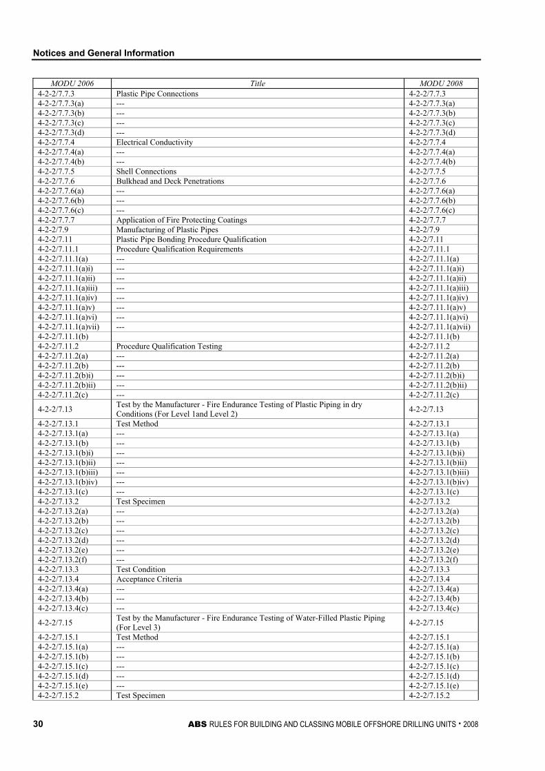
Notices and General Information
30 ABS RULES FOR BUILDING AND CLASSING MOBILE OFFSHORE DRILLING UNITS . 2008
MODU 2006 Title MODU 2008 4-2-2/7.7.3 Plastic Pipe Connections 4-2-2/7.7.3 4-2-2/7.7.3(a) --- 4-2-2/7.7.3(a) 4-2-2/7.7.3(b) --- 4-2-2/7.7.3(b) 4-2-2/7.7.3(c) --- 4-2-2/7.7.3(c) 4-2-2/7.7.3(d) --- 4-2-2/7.7.3(d) 4-2-2/7.7.4 Electrical Conductivity 4-2-2/7.7.4 4-2-2/7.7.4(a) --- 4-2-2/7.7.4(a) 4-2-2/7.7.4(b) --- 4-2-2/7.7.4(b) 4-2-2/7.7.5 Shell Connections 4-2-2/7.7.5 4-2-2/7.7.6 Bulkhead and Deck Penetrations 4-2-2/7.7.6 4-2-2/7.7.6(a) --- 4-2-2/7.7.6(a) 4-2-2/7.7.6(b) --- 4-2-2/7.7.6(b) 4-2-2/7.7.6(c) --- 4-2-2/7.7.6(c) 4-2-2/7.7.7 Application of Fire Protecting Coatings 4-2-2/7.7.7 4-2-2/7.9 Manufacturing of Plastic Pipes 4-2-2/7.9 4-2-2/7.11 Plastic Pipe Bonding Procedure Qualification 4-2-2/7.11 4-2-2/7.11.1 Procedure Qualification Requirements 4-2-2/7.11.1 4-2-2/7.11.1(a) --- 4-2-2/7.11.1(a) 4-2-2/7.11.1(a)i) --- 4-2-2/7.11.1(a)i) 4-2-2/7.11.1(a)ii) --- 4-2-2/7.11.1(a)ii) 4-2-2/7.11.1(a)iii) --- 4-2-2/7.11.1(a)iii) 4-2-2/7.11.1(a)iv) --- 4-2-2/7.11.1(a)iv) 4-2-2/7.11.1(a)v) --- 4-2-2/7.11.1(a)v) 4-2-2/7.11.1(a)vi) --- 4-2-2/7.11.1(a)vi) 4-2-2/7.11.1(a)vii) --- 4-2-2/7.11.1(a)vii) 4-2-2/7.11.1(b) 4-2-2/7.11.1(b) 4-2-2/7.11.2 Procedure Qualification Testing 4-2-2/7.11.2 4-2-2/7.11.2(a) --- 4-2-2/7.11.2(a) 4-2-2/7.11.2(b) --- 4-2-2/7.11.2(b) 4-2-2/7.11.2(b)i) --- 4-2-2/7.11.2(b)i) 4-2-2/7.11.2(b)ii) --- 4-2-2/7.11.2(b)ii) 4-2-2/7.11.2(c) --- 4-2-2/7.11.2(c)
4-2-2/7.13 Test by the Manufacturer - Fire Endurance Testing of Plastic Piping in dry Conditions (For Level 1and Level 2) 4-2-2/7.13
4-2-2/7.13.1 Test Method 4-2-2/7.13.1 4-2-2/7.13.1(a) --- 4-2-2/7.13.1(a) 4-2-2/7.13.1(b) --- 4-2-2/7.13.1(b) 4-2-2/7.13.1(b)i) --- 4-2-2/7.13.1(b)i) 4-2-2/7.13.1(b)ii) --- 4-2-2/7.13.1(b)ii) 4-2-2/7.13.1(b)iii) --- 4-2-2/7.13.1(b)iii) 4-2-2/7.13.1(b)iv) --- 4-2-2/7.13.1(b)iv) 4-2-2/7.13.1(c) --- 4-2-2/7.13.1(c) 4-2-2/7.13.2 Test Specimen 4-2-2/7.13.2 4-2-2/7.13.2(a) --- 4-2-2/7.13.2(a) 4-2-2/7.13.2(b) --- 4-2-2/7.13.2(b) 4-2-2/7.13.2(c) --- 4-2-2/7.13.2(c) 4-2-2/7.13.2(d) --- 4-2-2/7.13.2(d) 4-2-2/7.13.2(e) --- 4-2-2/7.13.2(e) 4-2-2/7.13.2(f) --- 4-2-2/7.13.2(f) 4-2-2/7.13.3 Test Condition 4-2-2/7.13.3 4-2-2/7.13.4 Acceptance Criteria 4-2-2/7.13.4 4-2-2/7.13.4(a) --- 4-2-2/7.13.4(a) 4-2-2/7.13.4(b) --- 4-2-2/7.13.4(b) 4-2-2/7.13.4(c) --- 4-2-2/7.13.4(c)
4-2-2/7.15 Test by the Manufacturer - Fire Endurance Testing of Water-Filled Plastic Piping (For Level 3) 4-2-2/7.15
4-2-2/7.15.1 Test Method 4-2-2/7.15.1 4-2-2/7.15.1(a) --- 4-2-2/7.15.1(a) 4-2-2/7.15.1(b) --- 4-2-2/7.15.1(b) 4-2-2/7.15.1(c) --- 4-2-2/7.15.1(c) 4-2-2/7.15.1(d) --- 4-2-2/7.15.1(d) 4-2-2/7.15.1(e) --- 4-2-2/7.15.1(e) 4-2-2/7.15.2 Test Specimen 4-2-2/7.15.2
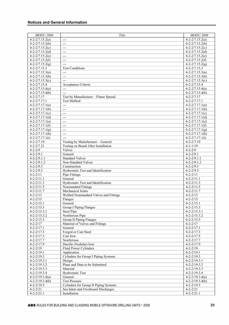
Notices and General Information
ABS RULES FOR BUILDING AND CLASSING MOBILE OFFSHORE DRILLING UNITS . 2008 31
MODU 2006 Title MODU 2008 4-2-2/7.15.2(a) --- 4-2-2/7.15.2(a) 4-2-2/7.15.2(b) --- 4-2-2/7.15.2(b) 4-2-2/7.15.2(c) --- 4-2-2/7.15.2(c) 4-2-2/7.15.2(d) --- 4-2-2/7.15.2(d) 4-2-2/7.15.2(e) --- 4-2-2/7.15.2(e) 4-2-2/7.15.2(f) --- 4-2-2/7.15.2(f) 4-2-2/7.15.2(g) --- 4-2-2/7.15.2(g) 4-2-2/7.15.3 Test Conditions 4-2-2/7.15.3 4-2-2/7.15.3(a) --- 4-2-2/7.15.3(a) 4-2-2/7.15.3(b) --- 4-2-2/7.15.3(b) 4-2-2/7.15.3(c) --- 4-2-2/7.15.3(c) 4-2-2/7.15.4 Acceptance Criteria 4-2-2/7.15.4 4-2-2/7.15.4(a) --- 4-2-2/7.15.4(a) 4-2-2/7.15.4(b) --- 4-2-2/7.15.4(b) 4-2-2/7.17 Test by Manufacturer – Flame Spread 4-2-2/7.17 4-2-2/7.17.1 Test Method 4-2-2/7.17.1 4-2-2/7.17.1(a) --- 4-2-2/7.17.1(a) 4-2-2/7.17.1(b) --- 4-2-2/7.17.1(b) 4-2-2/7.17.1(c) --- 4-2-2/7.17.1(c) 4-2-2/7.17.1(d) --- 4-2-2/7.17.1(d) 4-2-2/7.17.1(e) --- 4-2-2/7.17.1(e) 4-2-2/7.17.1(f) --- 4-2-2/7.17.1(f) 4-2-2/7.17.1(g) --- 4-2-2/7.17.1(g) 4-2-2/7.17.1(h) --- 4-2-2/7.17.1(h) 4-2-2/7.17.1(i) --- 4-2-2/7.17.1(i) 4-2-2/7.19 Testing by Manufacturer – General 4-2-2/7.19 4-2-2/7.21 Testing on Board After Installation 6-1-1/19 4-2-2/9 Valves 4-2-2/9 4-2-2/9.1 General 4-2-2/9.1 4-2-2/9.1.1 Standard Valves 4-2-2/9.1.1 4-2-2/9.1.2 Non-Standard Valves 4-2-2/9.1.2 4-2-2/9.3 Construction 4-2-2/9.3 4-2-2/9.5 Hydrostatic Test and Identification 4-2-2/9.5 4-2-2/11 Pipe Fittings 4-2-2/11 4-2-2/11.1 General 4-2-2/11.1 4-2-2/11.3 Hydrostatic Test and Identification 4-2-2/11.3 4-2-2/11.5 Nonstandard Fittings 4-2-2/11.5 4-2-2/11.7 Mechanical Joints 4-2-2/11.7 4-2-2/13 Welded Nonstandard Valves and Fittings 4-2-2/13 4-2-2/15 Flanges 4-2-2/15 4-2-2/15.1 General 4-2-2/15.1 4-2-2/15.3 Group I Piping Flanges 4-2-2/15.3 4-2-2/15.3.1 Steel Pipe 4-2-2/15.3.1 4-2-2/15.3.2 Nonferrous Pipe 4-2-2/15.3.2 4-2-2/15.5 Group II Piping Flanges 4-2-2/15.5 4-2-2/17 Material of Valves and Fittings 4-2-2/17 4-2-2/17.1 General 4-2-2/17.1 4-2-2/17.3 Forged or Cast Steel 4-2-2/17.3 4-2-2/17.5 Cast Iron 4-2-2/17.5 4-2-2/17.7 Nonferrous 4-2-2/17.7 4-2-2/17.9 Ductile (Nodular) Iron 4-2-2/17.9 4-2-2/19 Fluid Power Cylinders 4-2-2/19 4-2-2/19.1 Application 4-2-2/19.1 4-2-2/19.3 Cylinders for Group I Piping Systems 4-2-2/19.3 4-2-2/19.3.1 Design 4-2-2/19.3.1 4-2-2/19.3.2 Plans and Data to be Submitted 4-2-2/19.3.2 4-2-2/19.3.3 Material 4-2-2/19.3.3 4-2-2/19.3.4 Hydrostatic Test 4-2-2/19.3.4 4-2-2/19.3.4(a) General 4-2-2/19.3.4(a) 4-2-2/19.3.4(b) Test Pressure 4-2-2/19.3.4(b) 4-2-2/19.5 Cylinders for Group II Piping Systems 4-2-2/19.5 4-2-2/21 Sea Inlets and Overboard Discharges 4-2-2/21 4-2-2/21.1 Installation 4-2-2/21.1
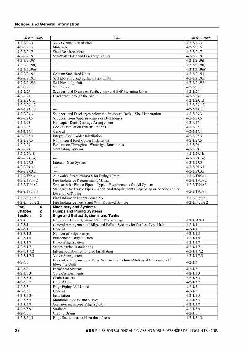
Notices and General Information
32 ABS RULES FOR BUILDING AND CLASSING MOBILE OFFSHORE DRILLING UNITS . 2008
MODU 2006 Title MODU 2008 4-2-2/21.3 Valve Connection to Shell 4-2-2/21.3 4-2-2/21.5 Materials 4-2-2/21.5 4-2-2/21.7 Shell Reinforcement 4-2-2/21.7 4-2-2/21.9 Sea-Water Inlet and Discharge Valves 4-2-2/21.9 4-2-2/21.9i) --- 4-2-2/21.9i) 4-2-2/21.9ii) --- 4-2-2/21.9ii) 4-2-2/21.9iii) --- 4-2-2/21.9iii) 4-2-2/21.9.1 Column Stabilized Units 4-2-2/21.9.1 4-2-2/21.9.2 Self Elevating and Surface Type Units 4-2-2/21.9.2 4-2-2/21.9.3 Self Elevating Units 4-2-2/21.9.3 4-2-2/21.11 Sea Chests 4-2-2/21.11 4-2-2/23 Scuppers and Drains on Surface-type and Self-Elevating Units 4-2-2/23 4-2-2/23.1 Discharges through the Shell 4-2-2/23.1 4-2-2/23.1.1 --- 4-2-2/23.1.1 4-2-2/23.1.2 --- 4-2-2/23.1.2 4-2-2/23.1.3 --- 4-2-2/23.1.3 4-2-2/23.3 Scuppers and Discharges below the Freeboard Deck – Shell Penetration 4-2-2/23.3 4-2-2/23.5 Scuppers from Superstructures or Deckhouses 4-2-2/23.5 4-2-2/25 Helicopter Deck Drainage Arrangement 4-2-6/17 4-2-2/27 Cooler Installation External to the Hull 4-2-2/27 4-2-2/27.1 General 4-2-2/27.1 4-2-2/27.3 Integral Keel Cooler Installation 4-2-2/27.3 4-2-2/27.5 Non-integral Keel Cooler Installation 4-2-2/27.5 4-2-2/29 Penetration Throughout Watertight Boundaries 4-2-2/29 4-2-2/29.1 Ventilating Systems 4-2-2/29.1 4-2-2/29.1i) --- 4-2-2/29.1i) 4-2-2/29.1ii) --- 4-2-2/29.1ii) 4-2-2/29.3 Internal Drain System 4-2-2/29.3 4-2-2/29.3.1 --- 4-2-2/29.3.1 4-2-2/29.3.2 --- 4-2-2/29.3.2 4-2-2/Table 1 Allowable Stress Values S for Piping N/mm2 4-2-2/Table 1 4-2-2/Table 2 Fire Endurance Requirements Matrix 4-2-2/Table 2 4-2-2/Table 3 Standards for Plastic Pipes – Typical Requirements for All System 4-2-2/Table 3
4-2-2/Table 4 Standards for Plastic Pipes – Additional Requirements Depending on Service and/or Location of Piping 4-2-2/Table 4
4-2-2/Figure 1 Fire Endurance Burner Assembly 4-2-2/Figure 1 4-2-2/Figure 2 Fire Endurance Test Stand With Mounted Sample 4-2-2/Figure 2 Part 4 Chapter 2 Section 3
Machinery and Systems Pumps and Piping Systems Bilge and Ballast Systems and Tanks
4-2-3 Bilge and Ballast Systems, Vents & Sounding 4-2-3, 4-2-4 4-2-3/1 General Arrangement of Bilge and Ballast Systems for Surface Type Units 4-2-4/1 4-2-3/1.1 General 4-2-4/1.1 4-2-3/1.3 Number of Bilge Pumps 4-2-4/1.3 4-2-3/1.5 Independent Bilge Suction 4-2-4/1.5 4-2-3/1.7 Direct Bilge Suction 4-2-4/1.7 4-2-3/1.7.1 Steam-engine Installations 4-2-4/1.7.1 4-2-3/1.7.2 Internal-combustion Engine Installation 4-2-4/1.7.2 4-2-3/1.7.3 Valve Arrangement 4-2-4/1.7.3
4-2-3/3 General Arrangement for Bilge Systems for Column-Stabilized Units and Self Elevating Units 4-2-4/3
4-2-3/3.1 Permanent Systems 4-2-4/3.1 4-2-3/3.3 Void Compartments 4-2-4/3.3 4-2-3/3.5 Chain Lockers 4-2-4/3.5 4-2-3/3.7 Bilge Alarm 4-2-4/3.7 4-2-3/5 Bilge Piping (All Units) 4-2-4/5 4-2-3/5.1 General 4-2-4/5.1 4-2-3/5.3 Installation 4-2-4/5.3 4-2-3/5.5 Manifolds, Cocks, and Valves 4-2-4/5.5 4-2-3/5.7 Common-main-type Bilge System 4-2-4/5.7 4-2-3/5.9 Strainers 4-2-4/5.9 4-2-3/5.11 Gravity Drains 4-2-4/5.11 4-2-3/5.13 Bilge Suctions from Hazardous Areas 4-2-4/5.13
Notices and General Information
ABS RULES FOR BUILDING AND CLASSING MOBILE OFFSHORE DRILLING UNITS . 2008 33
MODU 2006 Title MODU 2008 4-2-3/5.15 Exceptions 4-2-4/5.15 4-2-3/7 Bilge Pumps (All Units) 4-2-4/7 4-2-3/7.1 General 4-2-4/7.1 4-2-3/7.3 Arrangement and Capacity 4-2-4/7.3 4-2-3/9 Size of Bilge Suctions 4-2-4/9 4-2-3/9.1 Surface Type Units 4-2-4/9.1 4-2-3/9.1.1 Main Line 4-2-4/9.1.1 4-2-3/9.1.2 Branch Line 4-2-4/9.1.2 4-2-3/9.1.3 Main Line Reduction 4-2-4/9.1.3 4-2-3/9.1.4 Size Limits 4-2-4/9.1.4 4-2-3/9.3 Column-Stabilized Units and Self-Elevating Units 4-2-4/9.3 4-2-3/9.3.1 Main Line 4-2-4/9.3.1 4-2-3/9.3.2 Branch Line 4-2-4/9.3.2 4-2-3/9.3.3 Size Limits 4-2-4/9.3.3 4-2-3/11 Ballast Piping ( All Units) 4-2-4/11 4-2-3/11.1 General 4-2-4/11.1 4-2-3/11.3 Installation 4-2-4/11.3 4-2-3/11.5 Controls for Ballast Tank Valves 4-2-4/11.5 4-2-3/11.7 Exceptions 4-2-4/11.7 4-2-3/13 Ballast Systems for Column-Stabilized Units 4-2-4/13 4-2-3/13.1 General 4-2-4/13.1 4-2-3/13.1i) --- 4-2-4/13.1i) 4-2-3/13.1ii) --- 4-2-4/13.1ii) 4-2-3/13.3 Manifolds 4-2-4/13.3 4-2-3/13.5 Pumps 4-2-4/13.5 4-2-3/13.5.1 Number 4-2-4/13.5.1 4-2-3/13.5.2 Pump Performance 4-2-4/13.5.2 4-2-3/13.7 Ballast Control Features 4-2-4/13.7 4-2-3/13.7.1 Centralized Control Station 4-2-4/13.7.1 4-2-3/13.7.1(a) Location 4-2-4/13.7.1(a) 4-2-3/13.7.1(b) Controls and Indications 4-2-4/13.7.1(b) 4-2-3/13.7.1(b)i) --- 4-2-4/13.7.1(b)i) 4-2-3/13.7.1(b)ii) --- 4-2-4/13.7.1(b)ii) 4-2-3/13.7.1(b)iii) --- 4-2-4/13.7.1(b)iii) 4-2-3/13.7.1(b)iv) --- 4-2-4/13.7.1(b)iv) 4-2-3/13.7.1(b)v) --- 4-2-4/13.7.1(b)v) 4-2-3/13.7.1(b)vi) --- 4-2-4/13.7.1(b)vi) 4-2-3/13.7.1(b)vii) --- 4-2-4/13.7.1(b)vii) 4-2-3/13.7.1(b)viii) --- 4-2-4/13.7.1(b)viii) 4-2-3/13.7.1(b)ix) --- 4-2-4/13.7.1(b)ix) 4-2-3/13.7.1(c) Communication 4-2-4/13.7.1(c) 4-2-3/13.7.1(d) Back-up Station 4-2-4/13.7.1(d) 4-2-3/13.7.2 Independent Local Control 4-2-4/13.7.2 4-2-3/13.7.3 Safety Futures 4-2-4/13.7.3 4-2-3/13.7.3(a) Independence 4-2-4/13.7.3(a) 4-2-3/13.7.3(a)i) All Systems 4-2-4/13.7.3(a)i) 4-2-3/13.7.3(a)ii) Pump/Valve Control System 4-2-4/13.7.3(a)ii) 4-2-3/13.7.3(b) Dual Power Source 4-2-4/13.7.3(b) 4-2-3/13.7.3(c) Disconnects 4-2-4/13.7.3(c) 4-2-3/13.7.3(d) Electronic Systems 4-2-4/13.7.3(d) 4-2-3/13.7.3(e) Valve Controls 4-2-4/13.7.3(e) 4-2-3/13.7.4 Valve Positioning Indicating System 4-2-4/13.7.4 4-2-3/13.7.5 Draft Indicating System 4-2-4/13.7.5 4-2-3/13.7.6 Tank Level indicating System 4-2-4/13.7.6 4-2-3/15 Tank Vents and Overflows 4-2-3/1 4-2-3/15.1 General 4-2-3/1.1 4-2-3/15.3 Progressive Flooding Consideration 4-2-3/1.3 4-2-3/15.5 Height of Vent Pipes 4-2-3/1.5 4-2-3/15.7 Size 4-2-3/1.7 4-2-3/15.9 Termination of Vent Pipes 4-2-3/1.9 4-2-3/15.9.1 Termination on or Above Freeboard Deck 4-2-3/1.9.1 4-2-3/15.9.2 Termination in Machinery Spaces 4-2-3/1.9.2 4-2-3/15.9.3 Protection for Fuel Oil and Lubricating Oil Tanks 4-2-3/1.9.3
Notices and General Information
34 ABS RULES FOR BUILDING AND CLASSING MOBILE OFFSHORE DRILLING UNITS . 2008
MODU 2006 Title MODU 2008 4-2-3/15.9.4 Fuel Oil Tanks Vent Outlets 4-2-3/1.9.4 4-2-3/15.11 Overflow Pipes 4-2-3/1.11 4-2-3/17 Sounding Arrangements 4-2-3/3 4-2-3/17.1 General 4-2-3/3.1 4-2-3/17.3 Sounding Pipes 4-2-3/3.3 4-2-3/17.3.1 Oil Tanks 4-2-3/3.3.1 4-2-3/17.3.2 Other Tanks 4-2-3/3.3.2 4-2-3/17.3.3 Ignition of Spillage 4-2-3/3.3.3 4-2-3/17.3.3(a) Fuel Oil Tanks 4-2-3/3.3.3(a) 4-2-3/17.3.3(a)i) --- 4-2-3/3.3.3(a)i) 4-2-3/17.3.3(a)ii) --- 4-2-3/3.3.3(a)ii) 4-2-3/17.3.3(a)iii) --- 4-2-3/3.3.3(a)iii) 4-2-3/17.3.3(b) Lubricating Oil Tanks 4-2-3/3.3.3(b) 4-2-3/17.3.3(b)i) --- 4-2-3/3.3.3(b)i) 4-2-3/17.3.3(b)ii) --- 4-2-3/3.3.3(b)ii) 4-2-3/17.5 Gauge Glasses 4-2-3/3.5 4-2-3/17.7 Level Indicating Device 4-2-3/3.7 Part 4 Chapter 2 Section 4
Machinery and Systems Pumps and Piping Systems Fuel Oil and Other Piping Systems and Tanks
4-2-4 Fuel Oil and Other Piping Systems and Tanks 4-2-5, 4-2-6, 6-1-1 4-2-4/1 Fuel Oil Piping System – General 4-2-5/1 4-2-4/1.1 Arrangement 4-2-5/1.1 4-2-4/1.1.1 Tanks 4-2-5/1.1.1 4-2-4/1.1.2 Spillage 4-2-5/1.1.2 4-2-4/1.1.3 Sounding Arrangements 4-2-5/1.1.3 4-2-4/1.1.4 Service and Settlings Tanks 4-2-5/1.1.4 4-2-4/1.3 Piping, Valves and Fittings 4-2-5/1.3 4-2-4/1.5 Oil Heating Arrangements 4-2-5/1.5 4-2-4/1.5.1 Oil Heaters 4-2-5/1.5.1 4-2-4/1.5.2 Tanks 4-2-5/1.5.2 4-2-4/1.7 Fuel Oil Purifiers 4-2-5/1.7 4-2-4/3 Fuel Oil Transfer and Filling 4-2-5/3 4-2-4/3.1 General 4-2-5/3.1 4-2-4/3.3 Heating Coil 4-2-5/3.3 4-2-4/3.5 Pipes in Oil Tanks 4-2-5/3.5 4-2-4/3.7 Control Valves or Cocks 4-2-5/3.7 4-2-4/3.9 Valves on Oil Tanks 4-2-5/3.9 4-2-4/3.9i) --- 4-2-5/3.9i) 4-2-4/3.9ii) --- 4-2-5/3.9ii) 4-2-4/3.9iii) --- 4-2-5/3.9iii) 4-2-4/5 Fuel Oil Service System for Boilers 4-2-5/5 4-2-4/7 Fuel Oil Service System for Internal Combustion Engines 4-2-5/7 4-2-4/7.1 Fuel Oil Pumps and Oil Heaters 4-2-5/7.1 4-2-4/7.1.1 Transfer Pumps 4-2-5/7.1.1 4-2-4/7.1.2 Booster Pumps 4-2-5/7.1.2 4-2-4/7.1.3 Heaters 4-2-5/7.1.3 4-2-4/7.3 Oil Tanks and Drains for Fuel Oil System 4-2-5/7.3 4-2-4/7.5 Fuel Oil Pressure Piping 4-2-5/7.5 4-2-4/7.7 Fuel Oil Injecting System 4-2-5/7.7 4-2-4/7.7.1 General 4-2-5/7.7.1 4-2-4/7.7.2 Shielding of High Pressure Fuel Oil Piping 4-2-5/7.7.2 4-2-4/7.7.2(a) Injection Piping 4-2-5/7.7.2(a) 4-2-4/7.7.2(b) Fuel Oil Return Piping 4-2-5/7.7.2(b) 4-2-4/7.9 Piping Between Injection Pump and Booster Pumps 4-2-5/7.9 4-2-4/9 Low Flash Point Fuels 4-2-5/9 4-2-4/9.1 General 4-2-5/9.1 4-2-4/9.1.1 --- 4-2-5/9.1.1 4-2-4/9.1.2 --- 4-2-5/9.1.2 4-2-4/9.1.3 --- 4-2-5/9.1.3 4-2-4/9.3 Fuel Heating 4-2-5/9.3 4-2-4/9.5 Fuel Tank Vents 4-2-5/9.5 4-2-4/11 Lubricating Oil Systems 4-2-6/1
Notices and General Information
ABS RULES FOR BUILDING AND CLASSING MOBILE OFFSHORE DRILLING UNITS . 2008 35
MODU 2006 Title MODU 2008 4-2-4/11.1 General 4-2-6/1.1 4-2-4/11.3 Sight Flow Glasses 4-2-6/1.3 4-2-4/11.5 Turbines and Reduction Gears 4-2-6/1.5 4-2-4/11.7 Internal Combustion Engines and Reduction Gear 4-2-6/1.7 4-2-4/11.7.1 Lubricating Oil Pumps 4-2-6/1.7.1 4-2-4/11.7.2 Filters 4-2-6/1.7.2 4-2-4/11.7.3 Low Oil Pressure Alarm 4-2-6/1.7.3 4-2-4/11.7.4 Drain Pipes 4-2-6/1.7.4 4-2-4/11.9 Electrical machinery 4-2-6/1.9 4-2-4/13 Hydraulic Systems 4-2-6/3 4-2-4/13.1 General 4-2-6/3.1 4-2-4/13.3 Valves 4-2-6/3.3 4-2-4/13.3.1 General 4-2-6/3.3.1 4-2-4/13.3.2 Relief Valves 4-2-6/3.3.2 4-2-4/13.5 Piping 4-2-6/3.5 4-2-4/13.7 Pipe Fittings 4-2-6/3.7 4-2-4/13.7.1 Non-standard Fittings 4-2-6/3.7.1 4-2-4/13.7.2 Split Flanges 4-2-6/3.7.2 4-2-4/13.7.3 Straight Thread O Rings Connections 4-2-6/3.7.3 4-2-4/13.7.4 Tapered Threaded Connections 4-2-6/3.7.4 4-2-4/13.9 Hose 4-2-6/3.9 4-2-4/13.11 Accumulators 4-2-6/3.11 4-2-4/13.13 Fluid Power Cylinders 4-2-6/3.13 4-2-4/13.15 Design Pressure 4-2-6/3.15 4-2-4/13.17 Segregation of High Pressure Hydraulic Units 4-2-6/3.17 4-2-4/15 Fixed Oxygen – Acetylene Installations 4-2-6/5 4-2-4/15.1 Application 4-2-6/5.1 4-2-4/15.3 Gas Storage 4-2-6/5.3 4-2-4/15.3.1 Storage of Gas Cylinders 4-2-6/5.3.1 4-2-4/15.3.1(a) Storage Room 4-2-6/5.3.1(a) 4-2-4/15.3.1(b) Open Area 4-2-6/5.3.1(b) 4-2-4/15.3.1(c) Piping Passing Through Storage Room or Area 4-2-6/5.3.1(c) 4-2-4/15.3.2 Ventilation of Storage Room 4-2-6/5.3.2 4-2-4/15.3.3 Electrical Installation in Storage Room 4-2-6/5.3.3 4-2-4/15.5 Piping System Components 4-2-6/5.5 4-2-4/15.5.1 Pipe and Fittings 4-2-6/5.5.1 4-2-4/15.5.1(a) General 4-2-6/5.5.1(a) 4-2-4/15.5.1(b) Piping Materials 4-2-6/5.5.1(b) 4-2-4/15.5.1(c) Design Pressure 4-2-6/5.5.1(c) 4-2-4/15.5.1(d) Pipe Joints 4-2-6/5.5.1(d) 4-2-4/15.5.2 Pressure Relief Devices 4-2-6/5.5.2 4-2-4/15.5.3 System Arrangements 4-2-6/5.5.3 4-2-4/15.5.4 Gas Cylinders 4-2-6/5.5.4 4-2-4/15.7 Testing 6-1-1/21 4-2-4/17 Fuel Storage for Helicopter Facilities 4-2-6/7 4-2-4/17.1 General 4-2-6/7.1 4-2-4/17.1.1 Isolation 4-2-6/7.1.1 4-2-4/17.1.2 Hazardous Areas 4-2-6/7.1.2 4-2-4/17.1.2(a) Ventilation Capacity 4-2-6/7.1.2(a) 4-2-4/17.1.2(b) Exhaust Ventilation Duct and Fan 4-2-6/7.1.2(b) 4-2-4/17.1.2(c) Dewatering System 4-2-6/7.1.2(c) 4-2-4/17.1.3 Fuel Storage Tank Construction 4-2-6/7.1.3 4-2-4/17.1.4 Fuel Storage Tank Vents 4-2-6/7.1.4 4-2-4/17.1.5 Fuel Storage Tank Valves 4-2-6/7.1.5 4-2-4/17.3 Spill Containment 4-2-6/7.3 4-2-4/17.3.1 --- 4-2-6/7.3.1 4-2-4/17.3.2 --- 4-2-6/7.3.2 4-2-4/17.3.3 --- 4-2-6/7.3.3 4-2-4/19 Starting Air Systems 4-2-6/9 4-2-4/19.1 Design and Construction 4-2-6/9.1 4-2-4/19.3 Starting Air Capacity 4-2-6/9.3 4-2-4/19.3.1 Diesel Propulsion 4-2-6/9.3.1 4-2-4/19.3.2 Diesel-Electric Propulsion 4-2-6/9.3.2
Notices and General Information
36 ABS RULES FOR BUILDING AND CLASSING MOBILE OFFSHORE DRILLING UNITS . 2008
MODU 2006 Title MODU 2008 4-2-4/19.5 Protective Devices for Starting Air Mains 4-2-6/9.5 4-2-4/21 Cooling Water Systems for Internal Combustion Engines 4-2-6/11 4-2-4/21.1 General 4-2-6/11.1 4-2-4/21.3 Sea Suctions 4-2-6/11.3 4-2-4/21.5 Strainers 4-2-6/11.5 4-2-4/21.7 Circulating Water Pumps 4-2-6/11.7 4-2-4/23 Exhaust System 4-2-6/13 4-2-4/23.1 Exhaust Lines 4-2-6/13.1 4-2-4/23.3 Exhaust Gas Temperature 4-2-6/13.3 4-2-4/25 Valves in Atomizing Lines 4-2-6/15 Part 4 Chapter 3 Section 1
Machinery and Systems Electrical Installations General
4-3-1 General 4-3-1 and 6-1-1 4-3-1/1 Applications 4-3-1/1 4-3-1/3 Definitions 4-3-1/3 4-3-1/3.1 Earthed Distribution System 4-3-1/3.1 4-3-1/3.3 Essential Services 4-3-1/3.3 4-3-1/3.5 Explosion-proof (Flameproof) Equipment 4-3-1/3.5 4-3-1/3.5i) --- 4-3-1/3.5i) 4-3-1/3.5ii) --- 4-3-1/3.5ii) 4-3-1/3.7 Hazardous Area (Hazardous Location) 4-3-1/3.7 4-3-1/3.9 Hull-return System 4-3-1/3.9 4-3-1/3.11 Intrinsically-safe 4-3-1/3.11 4-3-1/3.11.1 Category "ia" 4-3-1/3.11.1 4-3-1/3.13 Increased Safety 4-3-1/3.13 4-3-1/3.15 Non-Periodic Duty Rating 4-3-1/3.15 4-3-1/3.17 Non-sparking Fan 4-3-1/3.17 4-3-1/3.19 Periodic Duty Rating 4-3-1/3.19 4-3-1/3.21 Portable Apparatus 4-3-1/3.21 4-3-1/3.23 Pressurized Equipment 4-3-1/3.23 4-3-1/3.25 Semi-enclosed Space 4-3-1/3.25 4-3-1/3.27 Separate Circuit 4-3-1/3.27 4-3-1/3.29 Short Circuit 4-3-1/3.29 4-3-1/3.31 Short-time Rating 4-3-1/3.31 4-3-1/5 Plans and Data to be Submitted 4-3-1/5 4-3-1/7 Standard Distribution System 4-3-1/7 4-3-1/9 Voltage and Frequency Variations 4-3-1/9 4-3-1/11 Materials 4-3-1/11 4-3-1/12 Grounding Arrangements 4-3-1/12 4-3-1/13 Insulation Materials 4-3-1/13 4-3-1/13.1 Class A Insulation 4-3-1/13.1 4-3-1/13.3 Class B Insulation 4-3-1/13.3 4-3-1/13.5 Class E Insulation 4-3-1/13.5 4-3-1/13.7 Class F Insulation 4-3-1/13.7 4-3-1/13.9 Class H Insulation 4-3-1/13.9 4-3-1/13.11 Insulation for Temperature Above 180°C (356°F) 4-3-1/13.11 4-3-1/15 Degree of Protection for Enclosure 4-3-1/15 4-3-1/17 Temperature Ratings 4-3-1/17 4-3-1/17.1 General 4-3-1/17.1 4-3-1/17.3 Reduced Ambient Temperature 4-3-1/17.3 4-3-1/17.3.1 Environmentally Controlled Spaces 4-3-1/17.3.1 4-3-1/17.3.1i) --- 4-3-1/17.3.1i) 4-3-1/17.3.1ii) --- 4-3-1/17.3.1ii) 4-3-1/17.3.1iii) --- 4-3-1/17.3.1iii) 4-3-1/17.3.1iv) --- 4-3-1/17.3.1iv) 4-3-1/17.3.2 Rating of Cables 4-3-1/17.3.2 4-3-1/17.3.3 Ambient Temperature Control Equipment 4-3-1/17.3.3 4-3-1/19 Clearances and Creepage Distances 4-3-1/19 4-3-1/21 Service Trial 6-1-1/27 4-3-1/21.1 Electrical Installation for Drilling Unit Main Service 6-1-1/27.1 4-3-1/21.3 Communication Facilities 6-1-1/27.3
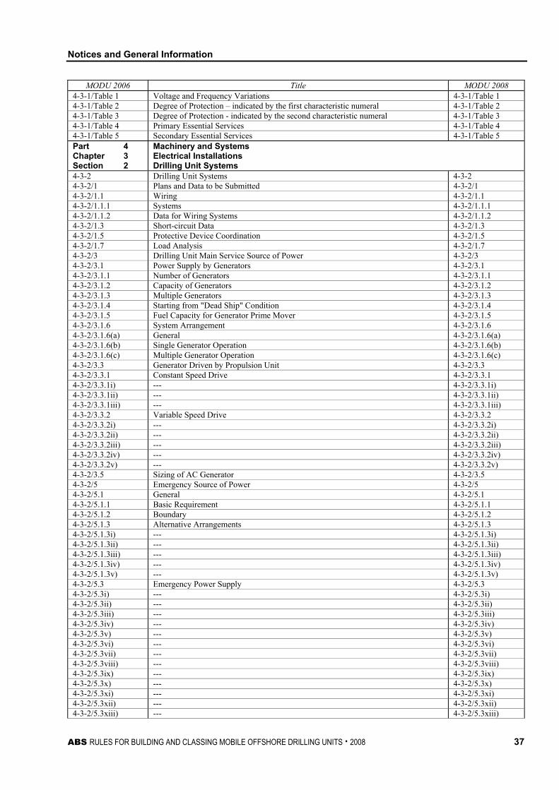
Notices and General Information
ABS RULES FOR BUILDING AND CLASSING MOBILE OFFSHORE DRILLING UNITS . 2008 37
MODU 2006 Title MODU 2008 4-3-1/Table 1 Voltage and Frequency Variations 4-3-1/Table 1 4-3-1/Table 2 Degree of Protection – indicated by the first characteristic numeral 4-3-1/Table 2 4-3-1/Table 3 Degree of Protection - indicated by the second characteristic numeral 4-3-1/Table 3 4-3-1/Table 4 Primary Essential Services 4-3-1/Table 4 4-3-1/Table 5 Secondary Essential Services 4-3-1/Table 5 Part 4 Chapter 3 Section 2
Machinery and Systems Electrical Installations Drilling Unit Systems
4-3-2 Drilling Unit Systems 4-3-2 4-3-2/1 Plans and Data to be Submitted 4-3-2/1 4-3-2/1.1 Wiring 4-3-2/1.1 4-3-2/1.1.1 Systems 4-3-2/1.1.1 4-3-2/1.1.2 Data for Wiring Systems 4-3-2/1.1.2 4-3-2/1.3 Short-circuit Data 4-3-2/1.3 4-3-2/1.5 Protective Device Coordination 4-3-2/1.5 4-3-2/1.7 Load Analysis 4-3-2/1.7 4-3-2/3 Drilling Unit Main Service Source of Power 4-3-2/3 4-3-2/3.1 Power Supply by Generators 4-3-2/3.1 4-3-2/3.1.1 Number of Generators 4-3-2/3.1.1 4-3-2/3.1.2 Capacity of Generators 4-3-2/3.1.2 4-3-2/3.1.3 Multiple Generators 4-3-2/3.1.3 4-3-2/3.1.4 Starting from "Dead Ship" Condition 4-3-2/3.1.4 4-3-2/3.1.5 Fuel Capacity for Generator Prime Mover 4-3-2/3.1.5 4-3-2/3.1.6 System Arrangement 4-3-2/3.1.6 4-3-2/3.1.6(a) General 4-3-2/3.1.6(a) 4-3-2/3.1.6(b) Single Generator Operation 4-3-2/3.1.6(b) 4-3-2/3.1.6(c) Multiple Generator Operation 4-3-2/3.1.6(c) 4-3-2/3.3 Generator Driven by Propulsion Unit 4-3-2/3.3 4-3-2/3.3.1 Constant Speed Drive 4-3-2/3.3.1 4-3-2/3.3.1i) --- 4-3-2/3.3.1i) 4-3-2/3.3.1ii) --- 4-3-2/3.3.1ii) 4-3-2/3.3.1iii) --- 4-3-2/3.3.1iii) 4-3-2/3.3.2 Variable Speed Drive 4-3-2/3.3.2 4-3-2/3.3.2i) --- 4-3-2/3.3.2i) 4-3-2/3.3.2ii) --- 4-3-2/3.3.2ii) 4-3-2/3.3.2iii) --- 4-3-2/3.3.2iii) 4-3-2/3.3.2iv) --- 4-3-2/3.3.2iv) 4-3-2/3.3.2v) --- 4-3-2/3.3.2v) 4-3-2/3.5 Sizing of AC Generator 4-3-2/3.5 4-3-2/5 Emergency Source of Power 4-3-2/5 4-3-2/5.1 General 4-3-2/5.1 4-3-2/5.1.1 Basic Requirement 4-3-2/5.1.1 4-3-2/5.1.2 Boundary 4-3-2/5.1.2 4-3-2/5.1.3 Alternative Arrangements 4-3-2/5.1.3 4-3-2/5.1.3i) --- 4-3-2/5.1.3i) 4-3-2/5.1.3ii) --- 4-3-2/5.1.3ii) 4-3-2/5.1.3iii) --- 4-3-2/5.1.3iii) 4-3-2/5.1.3iv) --- 4-3-2/5.1.3iv) 4-3-2/5.1.3v) --- 4-3-2/5.1.3v) 4-3-2/5.3 Emergency Power Supply 4-3-2/5.3 4-3-2/5.3i) --- 4-3-2/5.3i) 4-3-2/5.3ii) --- 4-3-2/5.3ii) 4-3-2/5.3iii) --- 4-3-2/5.3iii) 4-3-2/5.3iv) --- 4-3-2/5.3iv) 4-3-2/5.3v) --- 4-3-2/5.3v) 4-3-2/5.3vi) --- 4-3-2/5.3vi) 4-3-2/5.3vii) --- 4-3-2/5.3vii) 4-3-2/5.3viii) --- 4-3-2/5.3viii) 4-3-2/5.3ix) --- 4-3-2/5.3ix) 4-3-2/5.3x) --- 4-3-2/5.3x) 4-3-2/5.3xi) --- 4-3-2/5.3xi) 4-3-2/5.3xii) --- 4-3-2/5.3xii) 4-3-2/5.3xiii) --- 4-3-2/5.3xiii)
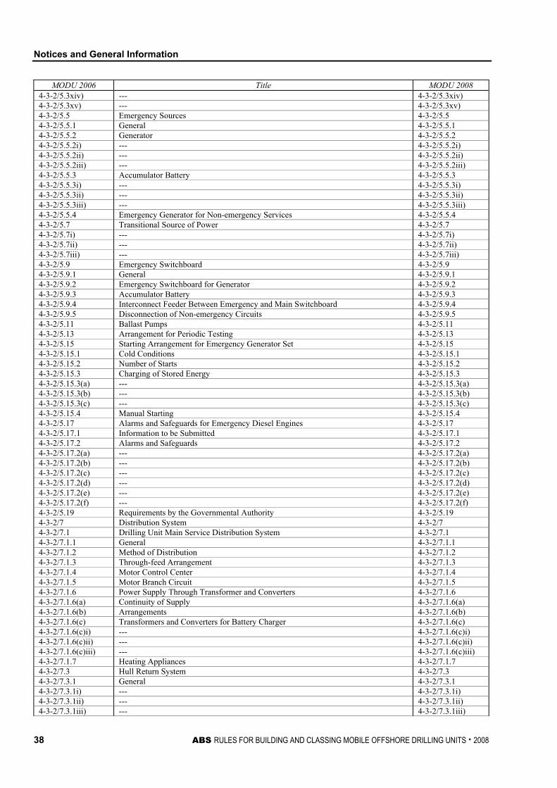
Notices and General Information
38 ABS RULES FOR BUILDING AND CLASSING MOBILE OFFSHORE DRILLING UNITS . 2008
MODU 2006 Title MODU 2008 4-3-2/5.3xiv) --- 4-3-2/5.3xiv) 4-3-2/5.3xv) --- 4-3-2/5.3xv) 4-3-2/5.5 Emergency Sources 4-3-2/5.5 4-3-2/5.5.1 General 4-3-2/5.5.1 4-3-2/5.5.2 Generator 4-3-2/5.5.2 4-3-2/5.5.2i) --- 4-3-2/5.5.2i) 4-3-2/5.5.2ii) --- 4-3-2/5.5.2ii) 4-3-2/5.5.2iii) --- 4-3-2/5.5.2iii) 4-3-2/5.5.3 Accumulator Battery 4-3-2/5.5.3 4-3-2/5.5.3i) --- 4-3-2/5.5.3i) 4-3-2/5.5.3ii) --- 4-3-2/5.5.3ii) 4-3-2/5.5.3iii) --- 4-3-2/5.5.3iii) 4-3-2/5.5.4 Emergency Generator for Non-emergency Services 4-3-2/5.5.4 4-3-2/5.7 Transitional Source of Power 4-3-2/5.7 4-3-2/5.7i) --- 4-3-2/5.7i) 4-3-2/5.7ii) --- 4-3-2/5.7ii) 4-3-2/5.7iii) --- 4-3-2/5.7iii) 4-3-2/5.9 Emergency Switchboard 4-3-2/5.9 4-3-2/5.9.1 General 4-3-2/5.9.1 4-3-2/5.9.2 Emergency Switchboard for Generator 4-3-2/5.9.2 4-3-2/5.9.3 Accumulator Battery 4-3-2/5.9.3 4-3-2/5.9.4 Interconnect Feeder Between Emergency and Main Switchboard 4-3-2/5.9.4 4-3-2/5.9.5 Disconnection of Non-emergency Circuits 4-3-2/5.9.5 4-3-2/5.11 Ballast Pumps 4-3-2/5.11 4-3-2/5.13 Arrangement for Periodic Testing 4-3-2/5.13 4-3-2/5.15 Starting Arrangement for Emergency Generator Set 4-3-2/5.15 4-3-2/5.15.1 Cold Conditions 4-3-2/5.15.1 4-3-2/5.15.2 Number of Starts 4-3-2/5.15.2 4-3-2/5.15.3 Charging of Stored Energy 4-3-2/5.15.3 4-3-2/5.15.3(a) --- 4-3-2/5.15.3(a) 4-3-2/5.15.3(b) --- 4-3-2/5.15.3(b) 4-3-2/5.15.3(c) --- 4-3-2/5.15.3(c) 4-3-2/5.15.4 Manual Starting 4-3-2/5.15.4 4-3-2/5.17 Alarms and Safeguards for Emergency Diesel Engines 4-3-2/5.17 4-3-2/5.17.1 Information to be Submitted 4-3-2/5.17.1 4-3-2/5.17.2 Alarms and Safeguards 4-3-2/5.17.2 4-3-2/5.17.2(a) --- 4-3-2/5.17.2(a) 4-3-2/5.17.2(b) --- 4-3-2/5.17.2(b) 4-3-2/5.17.2(c) --- 4-3-2/5.17.2(c) 4-3-2/5.17.2(d) --- 4-3-2/5.17.2(d) 4-3-2/5.17.2(e) --- 4-3-2/5.17.2(e) 4-3-2/5.17.2(f) --- 4-3-2/5.17.2(f) 4-3-2/5.19 Requirements by the Governmental Authority 4-3-2/5.19 4-3-2/7 Distribution System 4-3-2/7 4-3-2/7.1 Drilling Unit Main Service Distribution System 4-3-2/7.1 4-3-2/7.1.1 General 4-3-2/7.1.1 4-3-2/7.1.2 Method of Distribution 4-3-2/7.1.2 4-3-2/7.1.3 Through-feed Arrangement 4-3-2/7.1.3 4-3-2/7.1.4 Motor Control Center 4-3-2/7.1.4 4-3-2/7.1.5 Motor Branch Circuit 4-3-2/7.1.5 4-3-2/7.1.6 Power Supply Through Transformer and Converters 4-3-2/7.1.6 4-3-2/7.1.6(a) Continuity of Supply 4-3-2/7.1.6(a) 4-3-2/7.1.6(b) Arrangements 4-3-2/7.1.6(b) 4-3-2/7.1.6(c) Transformers and Converters for Battery Charger 4-3-2/7.1.6(c) 4-3-2/7.1.6(c)i) --- 4-3-2/7.1.6(c)i) 4-3-2/7.1.6(c)ii) --- 4-3-2/7.1.6(c)ii) 4-3-2/7.1.6(c)iii) --- 4-3-2/7.1.6(c)iii) 4-3-2/7.1.7 Heating Appliances 4-3-2/7.1.7 4-3-2/7.3 Hull Return System 4-3-2/7.3 4-3-2/7.3.1 General 4-3-2/7.3.1 4-3-2/7.3.1i) --- 4-3-2/7.3.1i) 4-3-2/7.3.1ii) --- 4-3-2/7.3.1ii) 4-3-2/7.3.1iii) --- 4-3-2/7.3.1iii)
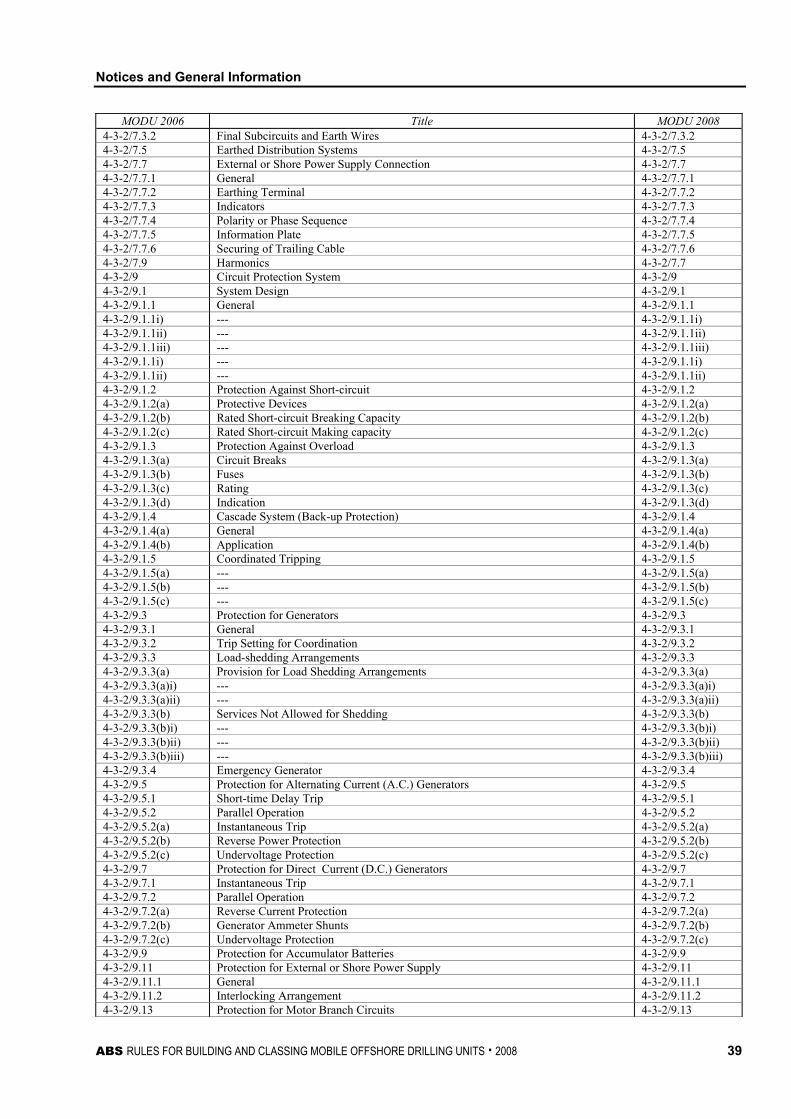
Notices and General Information
ABS RULES FOR BUILDING AND CLASSING MOBILE OFFSHORE DRILLING UNITS . 2008 39
MODU 2006 Title MODU 2008 4-3-2/7.3.2 Final Subcircuits and Earth Wires 4-3-2/7.3.2 4-3-2/7.5 Earthed Distribution Systems 4-3-2/7.5 4-3-2/7.7 External or Shore Power Supply Connection 4-3-2/7.7 4-3-2/7.7.1 General 4-3-2/7.7.1 4-3-2/7.7.2 Earthing Terminal 4-3-2/7.7.2 4-3-2/7.7.3 Indicators 4-3-2/7.7.3 4-3-2/7.7.4 Polarity or Phase Sequence 4-3-2/7.7.4 4-3-2/7.7.5 Information Plate 4-3-2/7.7.5 4-3-2/7.7.6 Securing of Trailing Cable 4-3-2/7.7.6 4-3-2/7.9 Harmonics 4-3-2/7.7 4-3-2/9 Circuit Protection System 4-3-2/9 4-3-2/9.1 System Design 4-3-2/9.1 4-3-2/9.1.1 General 4-3-2/9.1.1 4-3-2/9.1.1i) --- 4-3-2/9.1.1i) 4-3-2/9.1.1ii) --- 4-3-2/9.1.1ii) 4-3-2/9.1.1iii) --- 4-3-2/9.1.1iii) 4-3-2/9.1.1i) --- 4-3-2/9.1.1i) 4-3-2/9.1.1ii) --- 4-3-2/9.1.1ii) 4-3-2/9.1.2 Protection Against Short-circuit 4-3-2/9.1.2 4-3-2/9.1.2(a) Protective Devices 4-3-2/9.1.2(a) 4-3-2/9.1.2(b) Rated Short-circuit Breaking Capacity 4-3-2/9.1.2(b) 4-3-2/9.1.2(c) Rated Short-circuit Making capacity 4-3-2/9.1.2(c) 4-3-2/9.1.3 Protection Against Overload 4-3-2/9.1.3 4-3-2/9.1.3(a) Circuit Breaks 4-3-2/9.1.3(a) 4-3-2/9.1.3(b) Fuses 4-3-2/9.1.3(b) 4-3-2/9.1.3(c) Rating 4-3-2/9.1.3(c) 4-3-2/9.1.3(d) Indication 4-3-2/9.1.3(d) 4-3-2/9.1.4 Cascade System (Back-up Protection) 4-3-2/9.1.4 4-3-2/9.1.4(a) General 4-3-2/9.1.4(a) 4-3-2/9.1.4(b) Application 4-3-2/9.1.4(b) 4-3-2/9.1.5 Coordinated Tripping 4-3-2/9.1.5 4-3-2/9.1.5(a) --- 4-3-2/9.1.5(a) 4-3-2/9.1.5(b) --- 4-3-2/9.1.5(b) 4-3-2/9.1.5(c) --- 4-3-2/9.1.5(c) 4-3-2/9.3 Protection for Generators 4-3-2/9.3 4-3-2/9.3.1 General 4-3-2/9.3.1 4-3-2/9.3.2 Trip Setting for Coordination 4-3-2/9.3.2 4-3-2/9.3.3 Load-shedding Arrangements 4-3-2/9.3.3 4-3-2/9.3.3(a) Provision for Load Shedding Arrangements 4-3-2/9.3.3(a) 4-3-2/9.3.3(a)i) --- 4-3-2/9.3.3(a)i) 4-3-2/9.3.3(a)ii) --- 4-3-2/9.3.3(a)ii) 4-3-2/9.3.3(b) Services Not Allowed for Shedding 4-3-2/9.3.3(b) 4-3-2/9.3.3(b)i) --- 4-3-2/9.3.3(b)i) 4-3-2/9.3.3(b)ii) --- 4-3-2/9.3.3(b)ii) 4-3-2/9.3.3(b)iii) --- 4-3-2/9.3.3(b)iii) 4-3-2/9.3.4 Emergency Generator 4-3-2/9.3.4 4-3-2/9.5 Protection for Alternating Current (A.C.) Generators 4-3-2/9.5 4-3-2/9.5.1 Short-time Delay Trip 4-3-2/9.5.1 4-3-2/9.5.2 Parallel Operation 4-3-2/9.5.2 4-3-2/9.5.2(a) Instantaneous Trip 4-3-2/9.5.2(a) 4-3-2/9.5.2(b) Reverse Power Protection 4-3-2/9.5.2(b) 4-3-2/9.5.2(c) Undervoltage Protection 4-3-2/9.5.2(c) 4-3-2/9.7 Protection for Direct Current (D.C.) Generators 4-3-2/9.7 4-3-2/9.7.1 Instantaneous Trip 4-3-2/9.7.1 4-3-2/9.7.2 Parallel Operation 4-3-2/9.7.2 4-3-2/9.7.2(a) Reverse Current Protection 4-3-2/9.7.2(a) 4-3-2/9.7.2(b) Generator Ammeter Shunts 4-3-2/9.7.2(b) 4-3-2/9.7.2(c) Undervoltage Protection 4-3-2/9.7.2(c) 4-3-2/9.9 Protection for Accumulator Batteries 4-3-2/9.9 4-3-2/9.11 Protection for External or Shore Power Supply 4-3-2/9.11 4-3-2/9.11.1 General 4-3-2/9.11.1 4-3-2/9.11.2 Interlocking Arrangement 4-3-2/9.11.2 4-3-2/9.13 Protection for Motor Branch Circuits 4-3-2/9.13
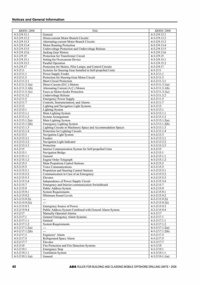
Notices and General Information
40 ABS RULES FOR BUILDING AND CLASSING MOBILE OFFSHORE DRILLING UNITS . 2008
MODU 2006 Title MODU 2008 4-3-2/9.13.1 General 4-3-2/9.13.1 4-3-2/9.13.2 Direct-current Motor Branch Circuits 4-3-2/9.13.2 4-3-2/9.13.3 Alternating-current Motor Branch Circuits 4-3-2/9.13.3 4-3-2/9.13.4 Motor Running Protection 4-3-2/9.13.4 4-3-2/9.13.5 Undervoltage Protection and Undervoltage Release 4-3-2/9.13.5 4-3-2/9.13.6 Jacking Gear Motors 4-3-2/9.13.6 4-3-2/9.15 Protection for Transformer Circuit 4-3-2/9.15 4-3-2/9.15.1 Setting for Overcurrent Device 4-3-2/9.15.1 4-3-2/9.15.2 Parallel Operation 4-3-2/9.15.2 4-3-2/9.17 Protection for Meters, Pilot Lamps, and Control Circuits 4-3-2/9.17 4-3-2/11 Systems for Steering Gear Installed in Self-propelled Units 4-3-2/11 4-3-2/11.1 Power Supply Feeder 4-3-2/11.1 4-3-2/11.3 Protection for Steering Gear Motor Circuit 4-3-2/11.3 4-3-2/11.3.1 Short Circuit Protection 4-3-2/11.3.1 4-3-2/11.3.1(a) Direct Current (D.C.) Motors 4-3-2/11.3.1(a) 4-3-2/11.3.1(b) Alternating Current (A.C.) Motors 4-3-2/11.3.1(b) 4-3-2/11.3.1(c) Fuses as Motor-feeder Protection 4-3-2/11.3.1(c) 4-3-2/11.3.2 Undervoltage Release 4-3-2/11.3.2 4-3-2/11.5 Emergency Power Supply 4-3-2/11.5 4-3-2/11.7 Controls, Instrumentation, and Alarms 4-3-2/11.7 4-3-2/13 Lighting and Navigation Light Systems 4-3-2/13 4-3-2/13.1 Lighting System 4-3-2/13.1 4-3-2/13.1.1 Main Lighting System 4-3-2/13.1.1 4-3-2/13.1.2 System Arrangement 4-3-2/13.1.2 4-3-2/13.1.2(a) Main Lighting System 4-3-2/13.1.2(a) 4-3-2/13.1.2(b) Emergency Lighting System 4-3-2/13.1.2(b) 4-3-2/13.1.3 Lighting Circuits in Machinery Space and Accommodation Spaces 4-3-2/13.1.3 4-3-2/13.1.4 Protection for Lighting Circuits 4-3-2/13.1.4 4-3-2/13.3 Navigation Light System 4-3-2/13.3 4-3-2/13.3.1 Feeders 4-3-2/13.3.1 4-3-2/13.3.2 Navigation Light Indicator 4-3-2/13.3.2 4-3-2/13.3.3 Protection 4-3-2/13.3.3 4-3-2/15 Interior Communication System for Self-propelled Units 4-3-2/15 4-3-2/15.1 Navigation Bridge 4-3-2/15.1 4-3-2/15.1.1 General 4-3-2/15.1.1 4-3-2/15.1.2 Engine Order Telegraph 4-3-2/15.1.2 4-3-2/15.3 Main Propulsion Control Stations 4-3-2/15.3 4-3-2/15.5 Voice Communications 4-3-2/15.5 4-3-2/15.5.1 Propulsion and Steering Control Stations 4-3-2/15.5.1 4-3-2/15.5.2 Communication in Case of an Emergency 4-3-2/15.5.2 4-3-2/15.5.3 Elevator 4-3-2/15.5.3 4-3-2/15.5.4 Independence of Power Supply Circuit 4-3-2/15.5.4 4-3-2/15.7 Emergency and Interior-communication Switchboard 4-3-2/15.7 4-3-2/15.9 Public Address System 4-3-2/15.9 4-3-2/15.9.1 System Requirements 4-3-2/15.9.1 4-3-2/15.9.2 Minimum Sound Levels 4-3-2/15.9.2 4-3-2/15.9.2i) --- 4-3-2/15.9.2i) 4-3-2/15.9.2ii) --- 4-3-2/15.9.2ii) 4-3-2/15.9.3 Emergency Source of Power 4-3-2/15.9.3 4-3-2/15.9.4 Public Address System Combined with General Alarm System 4-3-2/15.9.4 4-3-2/17 Manually Operated Alarms 4-3-2/17 4-3-2/17.1 General Emergency Alarm Systems 4-3-2/17.1 4-3-2/17.1.1 General 4-3-2/17.1.1 4-3-2/17.1.2 System Requirements 4-3-2/17.1.2 4-3-2/17.1.2(a) --- 4-3-2/17.1.2(a) 4-3-2/17.1.2(b) --- 4-3-2/17.1.2(b) 4-3-2/17.3 Engineers’ Alarm 4-3-2/17.3 4-3-2/17.5 Refrigerated Space Alarm 4-3-2/17.5 4-3-2/17.7 Elevator 4-3-2/17.7 4-3-2/19 Fire Protection and Fire Detection Systems 4-3-2/19 4-3-2/19.1 Emergency Stop 4-3-2/19.1 4-3-2/19.1.1 Ventilation System 4-3-2/19.1.1 4-3-2/19.1.1(a) General 4-3-2/19.1.1(a)
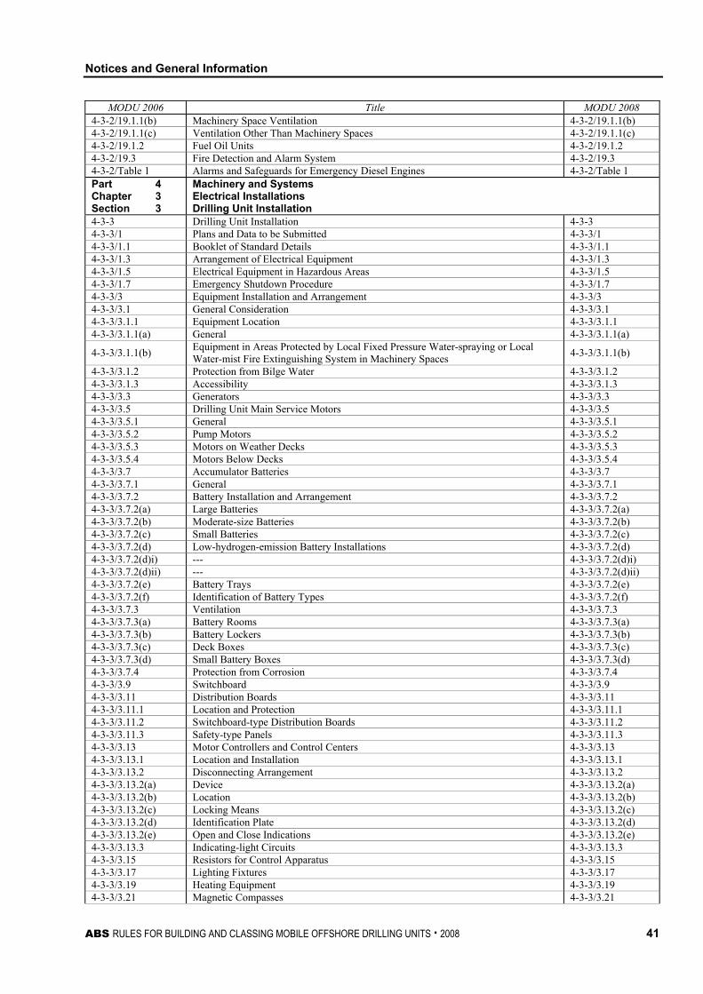
Notices and General Information
ABS RULES FOR BUILDING AND CLASSING MOBILE OFFSHORE DRILLING UNITS . 2008 41
MODU 2006 Title MODU 2008 4-3-2/19.1.1(b) Machinery Space Ventilation 4-3-2/19.1.1(b) 4-3-2/19.1.1(c) Ventilation Other Than Machinery Spaces 4-3-2/19.1.1(c) 4-3-2/19.1.2 Fuel Oil Units 4-3-2/19.1.2 4-3-2/19.3 Fire Detection and Alarm System 4-3-2/19.3 4-3-2/Table 1 Alarms and Safeguards for Emergency Diesel Engines 4-3-2/Table 1 Part 4 Chapter 3 Section 3
Machinery and Systems Electrical Installations Drilling Unit Installation
4-3-3 Drilling Unit Installation 4-3-3 4-3-3/1 Plans and Data to be Submitted 4-3-3/1 4-3-3/1.1 Booklet of Standard Details 4-3-3/1.1 4-3-3/1.3 Arrangement of Electrical Equipment 4-3-3/1.3 4-3-3/1.5 Electrical Equipment in Hazardous Areas 4-3-3/1.5 4-3-3/1.7 Emergency Shutdown Procedure 4-3-3/1.7 4-3-3/3 Equipment Installation and Arrangement 4-3-3/3 4-3-3/3.1 General Consideration 4-3-3/3.1 4-3-3/3.1.1 Equipment Location 4-3-3/3.1.1 4-3-3/3.1.1(a) General 4-3-3/3.1.1(a)
4-3-3/3.1.1(b) Equipment in Areas Protected by Local Fixed Pressure Water-spraying or Local Water-mist Fire Extinguishing System in Machinery Spaces 4-3-3/3.1.1(b)
4-3-3/3.1.2 Protection from Bilge Water 4-3-3/3.1.2 4-3-3/3.1.3 Accessibility 4-3-3/3.1.3 4-3-3/3.3 Generators 4-3-3/3.3 4-3-3/3.5 Drilling Unit Main Service Motors 4-3-3/3.5 4-3-3/3.5.1 General 4-3-3/3.5.1 4-3-3/3.5.2 Pump Motors 4-3-3/3.5.2 4-3-3/3.5.3 Motors on Weather Decks 4-3-3/3.5.3 4-3-3/3.5.4 Motors Below Decks 4-3-3/3.5.4 4-3-3/3.7 Accumulator Batteries 4-3-3/3.7 4-3-3/3.7.1 General 4-3-3/3.7.1 4-3-3/3.7.2 Battery Installation and Arrangement 4-3-3/3.7.2 4-3-3/3.7.2(a) Large Batteries 4-3-3/3.7.2(a) 4-3-3/3.7.2(b) Moderate-size Batteries 4-3-3/3.7.2(b) 4-3-3/3.7.2(c) Small Batteries 4-3-3/3.7.2(c) 4-3-3/3.7.2(d) Low-hydrogen-emission Battery Installations 4-3-3/3.7.2(d) 4-3-3/3.7.2(d)i) --- 4-3-3/3.7.2(d)i) 4-3-3/3.7.2(d)ii) --- 4-3-3/3.7.2(d)ii) 4-3-3/3.7.2(e) Battery Trays 4-3-3/3.7.2(e) 4-3-3/3.7.2(f) Identification of Battery Types 4-3-3/3.7.2(f) 4-3-3/3.7.3 Ventilation 4-3-3/3.7.3 4-3-3/3.7.3(a) Battery Rooms 4-3-3/3.7.3(a) 4-3-3/3.7.3(b) Battery Lockers 4-3-3/3.7.3(b) 4-3-3/3.7.3(c) Deck Boxes 4-3-3/3.7.3(c) 4-3-3/3.7.3(d) Small Battery Boxes 4-3-3/3.7.3(d) 4-3-3/3.7.4 Protection from Corrosion 4-3-3/3.7.4 4-3-3/3.9 Switchboard 4-3-3/3.9 4-3-3/3.11 Distribution Boards 4-3-3/3.11 4-3-3/3.11.1 Location and Protection 4-3-3/3.11.1 4-3-3/3.11.2 Switchboard-type Distribution Boards 4-3-3/3.11.2 4-3-3/3.11.3 Safety-type Panels 4-3-3/3.11.3 4-3-3/3.13 Motor Controllers and Control Centers 4-3-3/3.13 4-3-3/3.13.1 Location and Installation 4-3-3/3.13.1 4-3-3/3.13.2 Disconnecting Arrangement 4-3-3/3.13.2 4-3-3/3.13.2(a) Device 4-3-3/3.13.2(a) 4-3-3/3.13.2(b) Location 4-3-3/3.13.2(b) 4-3-3/3.13.2(c) Locking Means 4-3-3/3.13.2(c) 4-3-3/3.13.2(d) Identification Plate 4-3-3/3.13.2(d) 4-3-3/3.13.2(e) Open and Close Indications 4-3-3/3.13.2(e) 4-3-3/3.13.3 Indicating-light Circuits 4-3-3/3.13.3 4-3-3/3.15 Resistors for Control Apparatus 4-3-3/3.15 4-3-3/3.17 Lighting Fixtures 4-3-3/3.17 4-3-3/3.19 Heating Equipment 4-3-3/3.19 4-3-3/3.21 Magnetic Compasses 4-3-3/3.21
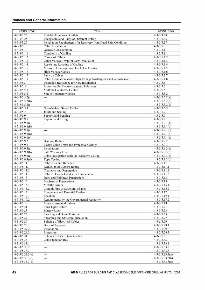
Notices and General Information
42 ABS RULES FOR BUILDING AND CLASSING MOBILE OFFSHORE DRILLING UNITS . 2008
MODU 2006 Title MODU 2008 4-3-3/3.23 Portable Equipment Outlets 4-3-3/3.23 4-3-3/3.25 Receptacles and Plugs of Different Rating 4-3-3/3.25 4-3-3/3.27 Installation Requirements for Recovery from Dead Ship Condition 4-3-3/3.27 4-3-3/5 Cable Installation 4-3-3/5 4-3-3/5.1 General Consideration 4-3-3/5.1 4-3-3/5.1.1 Continuity of Cabling 4-3-3/5.1.1 4-3-3/5.1.2 Choice of Cables 4-3-3/5.1.2 4-3-3/5.1.3 Cable Voltage Drop for New Installation 4-3-3/5.1.3 4-3-3/5.1.4 Restricting Locating of Cabling 4-3-3/5.1.4 4-3-3/5.1.5 Means of Drainage from Cable Enclosures 4-3-3/5.1.5 4-3-3/5.1.6 High Voltage Cables 4-3-3/5.1.6 4-3-3/5.1.7 Paint on Cables 4-3-3/5.1.7 4-3-3/5.1.8 Cable Installation above High Voltage Switchgear and Control-Gear 4-3-3/5.1.8 4-3-3/5.3 Insulation Resistance for New Installation 4-3-3/5.3 4-3-3/5.5 Protection for Electro-magnetic Induction 4-3-3/5.5 4-3-3/5.5.1 Multiple Conductor Cables 4-3-3/5.5.1 4-3-3/5.5.2 Single Conductor Cables 4-3-3/5.5.2 4-3-3/5.5.2(a) --- 4-3-3/5.5.2(a) 4-3-3/5.5.2(b) --- 4-3-3/5.5.2(b) 4-3-3/5.5.2(c) --- 4-3-3/5.5.2(c) 4-3-3/5.5.3 Non-shielded Signal Cables 4-3-3/5.5.3 4-3-3/5.7 Joints and Sealing 4-3-3/5.7 4-3-3/5.9 Support and Bending 4-3-3/5.9 4-3-3/5.9.1 Support and Fixing 4-3-3/5.9.1 4-3-3/5.9.1(a) --- 4-3-3/5.9.1(a) 4-3-3/5.9.1(b) --- 4-3-3/5.9.1(b) 4-3-3/5.9.1(c) --- 4-3-3/5.9.1(c) 4-3-3/5.9.1(d) --- 4-3-3/5.9.1(d) 4-3-3/5.9.1(e) --- 4-3-3/5.9.1(e) 4-3-3/5.9.2 Bending Radius 4-3-3/5.9.2 4-3-3/5.9.3 Plastic Cable Trays and Protective Casings 4-3-3/5.9.3 4-3-3/5.9.3(a) Installations 4-3-3/5.9.3(a) 4-3-3/5.9.3(b) Safe Working Load 4-3-3/5.9.3(b) 4-3-3/5.9.3(c) Cable Occupation Ratio in Protective Casing 4-3-3/5.9.3(c) 4-3-3/5.9.3(d) Type Testing 4-3-3/5.9.3(d) 4-3-3/5.11 Cable Run and Bunches 4-3-3/5.11 4-3-3/5.11.1 Reduction of Current Rating 4-3-3/5.11.1 4-3-3/5.11.2 Clearance and Segregation 4-3-3/5.11.2 4-3-3/5.11.3 Cable of Lower Conductor Temperature 4-3-3/5.11.3 4-3-3/5.13 Deck and Bulkhead Penetrations 4-3-3/5.13 4-3-3/5.15 Mechanical Penetrations 4-3-3/5.15 4-3-3/5.15.1 Metallic Armor 4-3-3/5.15.1 4-3-3/5.15.2 Conduit Pipe or Structural Shapes 4-3-3/5.15.2 4-3-3/5.17 Emergency and Essential Feeders 4-3-3/5.17 4-3-3/5.17.1 Location 4-3-3/5.17.1 4-3-3/5.17.2 Requirements by the Governmental Authority 4-3-3/5.17.2 4-3-3/5.19 Mineral Insulated Cables 4-3-3/5.19 4-3-3/5.21 Fiber Optic Cables 4-3-3/5.21 4-3-3/5.23 Battery Room 4-3-3/5.23 4-3-3/5.25 Paneling and Dome Fixtures 4-3-3/5.25 4-3-3/5.27 Sheathing and Structural Insulation 4-3-3/5.27 4-3-3/5.29 Splicing of Electrical Cables 4-3-3/5.29 4-3-3/5.29.1 Basis of Approval 4-3-3/5.29.1 4-3-3/5.29.2 Installation 4-3-3/5.29.2 4-3-3/5.29.3 Protection 4-3-3/5.29.3 4-3-3/5.31 Splicing of Fiber Optic Cables 4-3-3/5.31 4-3-3/5.33 Cable Junction Box 4-3-3/5.33 4-3-3/5.33.1 --- 4-3-3/5.33.1 4-3-3/5.33.2 --- 4-3-3/5.33.2 4-3-3/5.33.3 --- 4-3-3/5.33.3 4-3-3/5.33.3(a) --- 4-3-3/5.33.3(a) 4-3-3/5.33.3(b) --- 4-3-3/5.33.3(b) 4-3-3/5.33.3(c) --- 4-3-3/5.33.3(c)
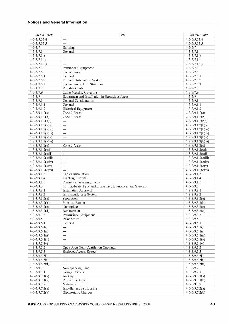
Notices and General Information
ABS RULES FOR BUILDING AND CLASSING MOBILE OFFSHORE DRILLING UNITS . 2008 43
MODU 2006 Title MODU 2008 4-3-3/5.33.4 --- 4-3-3/5.33.4 4-3-3/5.33.5 --- 4-3-3/5.33.5 4-3-3/7 Earthing 4-3-3/7 4-3-3/7.1 General 4-3-3/7.1 4-3-3/7.1i) --- 4-3-3/7.1i) 4-3-3/7.1ii) --- 4-3-3/7.1ii) 4-3-3/7.1iii) --- 4-3-3/7.1iii) 4-3-3/7.3 Permanent Equipment 4-3-3/7.3 4-3-3/7.5 Connections 4-3-3/7.5 4-3-3/7.5.1 General 4-3-3/7.5.1 4-3-3/7.5.2 Earthed Distribution System 4-3-3/7.5.2 4-3-3/7.5.3 Connection to Hull Structure 4-3-3/7.5.3 4-3-3/7.7 Portable Cords 4-3-3/7.7 4-3-3/7.9 Cable Metallic Covering 4-3-3/7.9 4-3-3/9 Equipment and Installation in Hazardous Areas 4-3-3/9 4-3-3/9.1 General Consideration 4-3-3/9.1 4-3-3/9.1.1 General 4-3-3/9.1.1 4-3-3/9.1.2 Electrical Equipment 4-3-3/9.1.2 4-3-3/9.1.2(a) Zone 0 Areas 4-3-3/9.1.2(a) 4-3-3/9.1.2(b) Zone 1 Areas 4-3-3/9.1.2(b) 4-3-3/9.1.2(b)i) --- 4-3-3/9.1.2(b)i) 4-3-3/9.1.2(b)ii) --- 4-3-3/9.1.2(b)ii) 4-3-3/9.1.2(b)iii) --- 4-3-3/9.1.2(b)iii) 4-3-3/9.1.2(b)iv) --- 4-3-3/9.1.2(b)iv) 4-3-3/9.1.2(b)v) --- 4-3-3/9.1.2(b)v) 4-3-3/9.1.2(b)vi) --- 4-3-3/9.1.2(b)vi) 4-3-3/9.1.2(c) Zone 2 Areas 4-3-3/9.1.2(c) 4-3-3/9.1.2(c)i) --- 4-3-3/9.1.2(c)i) 4-3-3/9.1.2(c)ii) --- 4-3-3/9.1.2(c)ii) 4-3-3/9.1.2(c)iii) --- 4-3-3/9.1.2(c)iii) 4-3-3/9.1.2(c)iv) --- 4-3-3/9.1.2(c)iv) 4-3-3/9.1.2(c)v) --- 4-3-3/9.1.2(c)v) 4-3-3/9.1.2(c)vi) --- 4-3-3/9.1.2(c)vi) 4-3-3/9.1.3 Cables Installation 4-3-3/9.1.3 4-3-3/9.1.4 Lighting Circuits 4-3-3/9.1.4 4-3-3/9.1.5 Permanent Warning Plates 4-3-3/9.1.5 4-3-3/9.3 Certified-safe Type and Pressurized Equipment and Systems 4-3-3/9.3 4-3-3/9.3.1 Installation Approval 4-3-3/9.3.1 4-3-3/9.3.2 Intrinsically-safe System 4-3-3/9.3.2 4-3-3/9.3.2(a) Separation 4-3-3/9.3.2(a) 4-3-3/9.3.2(b) Physical Barrier 4-3-3/9.3.2(b) 4-3-3/9.3.2(c) Nameplate 4-3-3/9.3.2(c) 4-3-3/9.3.2(d) Replacement 4-3-3/9.3.2(d) 4-3-3/9.3.3 Pressurized Equipment 4-3-3/9.3.3 4-3-3/9.5 Paint Stores 4-3-3/9.5 4-3-3/9.5.1 General 4-3-3/9.5.1 4-3-3/9.5.1i) --- 4-3-3/9.5.1i) 4-3-3/9.5.1ii) --- 4-3-3/9.5.1ii) 4-3-3/9.5.1iii) --- 4-3-3/9.5.1iii) 4-3-3/9.5.1iv) --- 4-3-3/9.5.1iv) 4-3-3/9.5.1v) --- 4-3-3/9.5.1v) 4-3-3/9.5.2 Open Area Near Ventilation Openings 4-3-3/9.5.2 4-3-3/9.5.3 Enclosed Access Spaces 4-3-3/9.5.3 4-3-3/9.5.3i) --- 4-3-3/9.5.3i) 4-3-3/9.5.3ii) --- 4-3-3/9.5.3ii) 4-3-3/9.5.3iii) --- 4-3-3/9.5.3iii) 4-3-3/9.7 Non-sparking Fans 4-3-3/9.7 4-3-3/9.7.1 Design Criteria 4-3-3/9.7.1 4-3-3/9.7.1(a) Air Gap 4-3-3/9.7.1(a) 4-3-3/9.7.1(b) Protection Screen 4-3-3/9.7.1(b) 4-3-3/9.7.2 Materials 4-3-3/9.7.2 4-3-3/9.7.2(a) Impeller and its Housing 4-3-3/9.7.2(a) 4-3-3/9.7.2(b) Electrostatic Charges 4-3-3/9.7.2(b)
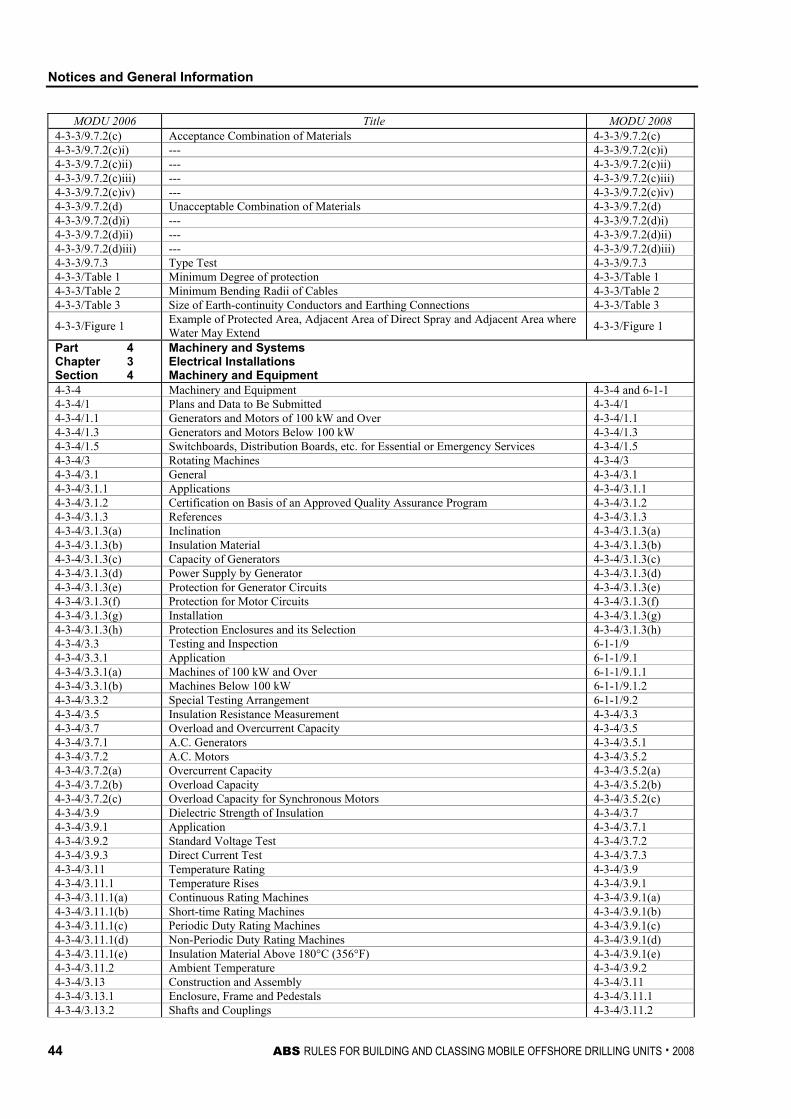
Notices and General Information
44 ABS RULES FOR BUILDING AND CLASSING MOBILE OFFSHORE DRILLING UNITS . 2008
MODU 2006 Title MODU 2008 4-3-3/9.7.2(c) Acceptance Combination of Materials 4-3-3/9.7.2(c) 4-3-3/9.7.2(c)i) --- 4-3-3/9.7.2(c)i) 4-3-3/9.7.2(c)ii) --- 4-3-3/9.7.2(c)ii) 4-3-3/9.7.2(c)iii) --- 4-3-3/9.7.2(c)iii) 4-3-3/9.7.2(c)iv) --- 4-3-3/9.7.2(c)iv) 4-3-3/9.7.2(d) Unacceptable Combination of Materials 4-3-3/9.7.2(d) 4-3-3/9.7.2(d)i) --- 4-3-3/9.7.2(d)i) 4-3-3/9.7.2(d)ii) --- 4-3-3/9.7.2(d)ii) 4-3-3/9.7.2(d)iii) --- 4-3-3/9.7.2(d)iii) 4-3-3/9.7.3 Type Test 4-3-3/9.7.3 4-3-3/Table 1 Minimum Degree of protection 4-3-3/Table 1 4-3-3/Table 2 Minimum Bending Radii of Cables 4-3-3/Table 2 4-3-3/Table 3 Size of Earth-continuity Conductors and Earthing Connections 4-3-3/Table 3
4-3-3/Figure 1 Example of Protected Area, Adjacent Area of Direct Spray and Adjacent Area where Water May Extend 4-3-3/Figure 1
Part 4 Chapter 3 Section 4
Machinery and Systems Electrical Installations Machinery and Equipment
4-3-4 Machinery and Equipment 4-3-4 and 6-1-1 4-3-4/1 Plans and Data to Be Submitted 4-3-4/1 4-3-4/1.1 Generators and Motors of 100 kW and Over 4-3-4/1.1 4-3-4/1.3 Generators and Motors Below 100 kW 4-3-4/1.3 4-3-4/1.5 Switchboards, Distribution Boards, etc. for Essential or Emergency Services 4-3-4/1.5 4-3-4/3 Rotating Machines 4-3-4/3 4-3-4/3.1 General 4-3-4/3.1 4-3-4/3.1.1 Applications 4-3-4/3.1.1 4-3-4/3.1.2 Certification on Basis of an Approved Quality Assurance Program 4-3-4/3.1.2 4-3-4/3.1.3 References 4-3-4/3.1.3 4-3-4/3.1.3(a) Inclination 4-3-4/3.1.3(a) 4-3-4/3.1.3(b) Insulation Material 4-3-4/3.1.3(b) 4-3-4/3.1.3(c) Capacity of Generators 4-3-4/3.1.3(c) 4-3-4/3.1.3(d) Power Supply by Generator 4-3-4/3.1.3(d) 4-3-4/3.1.3(e) Protection for Generator Circuits 4-3-4/3.1.3(e) 4-3-4/3.1.3(f) Protection for Motor Circuits 4-3-4/3.1.3(f) 4-3-4/3.1.3(g) Installation 4-3-4/3.1.3(g) 4-3-4/3.1.3(h) Protection Enclosures and its Selection 4-3-4/3.1.3(h) 4-3-4/3.3 Testing and Inspection 6-1-1/9 4-3-4/3.3.1 Application 6-1-1/9.1 4-3-4/3.3.1(a) Machines of 100 kW and Over 6-1-1/9.1.1 4-3-4/3.3.1(b) Machines Below 100 kW 6-1-1/9.1.2 4-3-4/3.3.2 Special Testing Arrangement 6-1-1/9.2 4-3-4/3.5 Insulation Resistance Measurement 4-3-4/3.3 4-3-4/3.7 Overload and Overcurrent Capacity 4-3-4/3.5 4-3-4/3.7.1 A.C. Generators 4-3-4/3.5.1 4-3-4/3.7.2 A.C. Motors 4-3-4/3.5.2 4-3-4/3.7.2(a) Overcurrent Capacity 4-3-4/3.5.2(a) 4-3-4/3.7.2(b) Overload Capacity 4-3-4/3.5.2(b) 4-3-4/3.7.2(c) Overload Capacity for Synchronous Motors 4-3-4/3.5.2(c) 4-3-4/3.9 Dielectric Strength of Insulation 4-3-4/3.7 4-3-4/3.9.1 Application 4-3-4/3.7.1 4-3-4/3.9.2 Standard Voltage Test 4-3-4/3.7.2 4-3-4/3.9.3 Direct Current Test 4-3-4/3.7.3 4-3-4/3.11 Temperature Rating 4-3-4/3.9 4-3-4/3.11.1 Temperature Rises 4-3-4/3.9.1 4-3-4/3.11.1(a) Continuous Rating Machines 4-3-4/3.9.1(a) 4-3-4/3.11.1(b) Short-time Rating Machines 4-3-4/3.9.1(b) 4-3-4/3.11.1(c) Periodic Duty Rating Machines 4-3-4/3.9.1(c) 4-3-4/3.11.1(d) Non-Periodic Duty Rating Machines 4-3-4/3.9.1(d) 4-3-4/3.11.1(e) Insulation Material Above 180°C (356°F) 4-3-4/3.9.1(e) 4-3-4/3.11.2 Ambient Temperature 4-3-4/3.9.2 4-3-4/3.13 Construction and Assembly 4-3-4/3.11 4-3-4/3.13.1 Enclosure, Frame and Pedestals 4-3-4/3.11.1 4-3-4/3.13.2 Shafts and Couplings 4-3-4/3.11.2
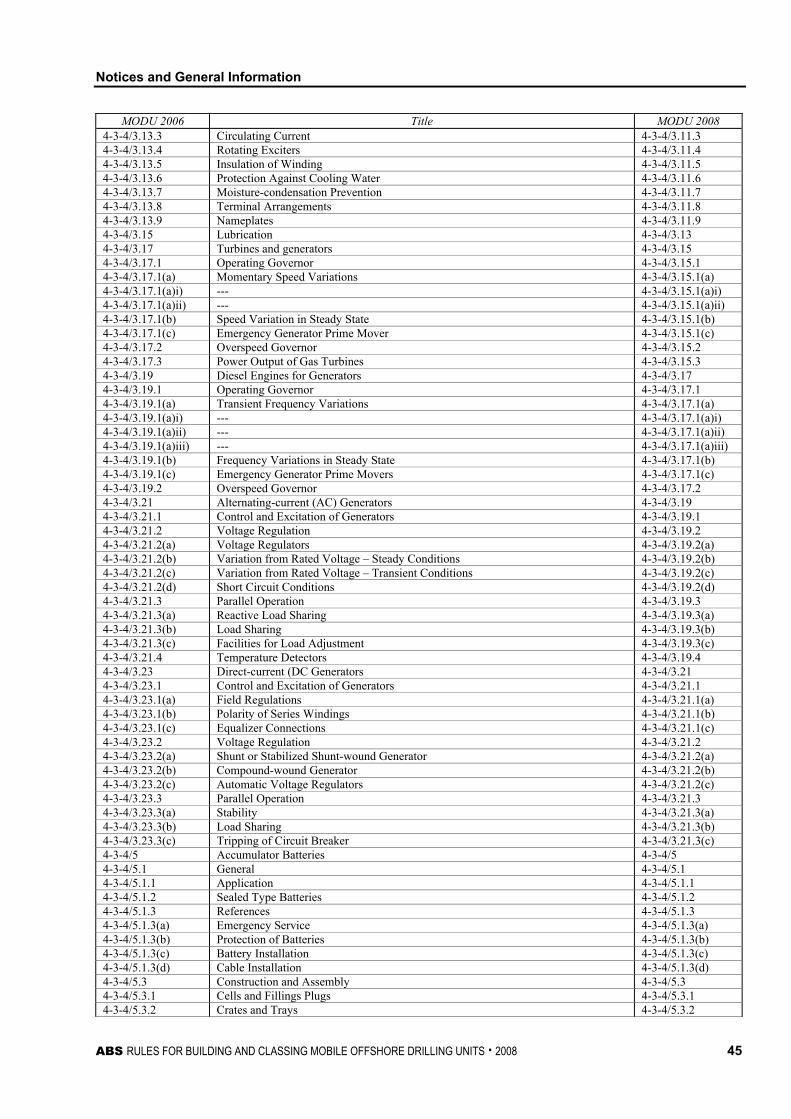
Notices and General Information
ABS RULES FOR BUILDING AND CLASSING MOBILE OFFSHORE DRILLING UNITS . 2008 45
MODU 2006 Title MODU 2008 4-3-4/3.13.3 Circulating Current 4-3-4/3.11.3 4-3-4/3.13.4 Rotating Exciters 4-3-4/3.11.4 4-3-4/3.13.5 Insulation of Winding 4-3-4/3.11.5 4-3-4/3.13.6 Protection Against Cooling Water 4-3-4/3.11.6 4-3-4/3.13.7 Moisture-condensation Prevention 4-3-4/3.11.7 4-3-4/3.13.8 Terminal Arrangements 4-3-4/3.11.8 4-3-4/3.13.9 Nameplates 4-3-4/3.11.9 4-3-4/3.15 Lubrication 4-3-4/3.13 4-3-4/3.17 Turbines and generators 4-3-4/3.15 4-3-4/3.17.1 Operating Governor 4-3-4/3.15.1 4-3-4/3.17.1(a) Momentary Speed Variations 4-3-4/3.15.1(a) 4-3-4/3.17.1(a)i) --- 4-3-4/3.15.1(a)i) 4-3-4/3.17.1(a)ii) --- 4-3-4/3.15.1(a)ii) 4-3-4/3.17.1(b) Speed Variation in Steady State 4-3-4/3.15.1(b) 4-3-4/3.17.1(c) Emergency Generator Prime Mover 4-3-4/3.15.1(c) 4-3-4/3.17.2 Overspeed Governor 4-3-4/3.15.2 4-3-4/3.17.3 Power Output of Gas Turbines 4-3-4/3.15.3 4-3-4/3.19 Diesel Engines for Generators 4-3-4/3.17 4-3-4/3.19.1 Operating Governor 4-3-4/3.17.1 4-3-4/3.19.1(a) Transient Frequency Variations 4-3-4/3.17.1(a) 4-3-4/3.19.1(a)i) --- 4-3-4/3.17.1(a)i) 4-3-4/3.19.1(a)ii) --- 4-3-4/3.17.1(a)ii) 4-3-4/3.19.1(a)iii) --- 4-3-4/3.17.1(a)iii) 4-3-4/3.19.1(b) Frequency Variations in Steady State 4-3-4/3.17.1(b) 4-3-4/3.19.1(c) Emergency Generator Prime Movers 4-3-4/3.17.1(c) 4-3-4/3.19.2 Overspeed Governor 4-3-4/3.17.2 4-3-4/3.21 Alternating-current (AC) Generators 4-3-4/3.19 4-3-4/3.21.1 Control and Excitation of Generators 4-3-4/3.19.1 4-3-4/3.21.2 Voltage Regulation 4-3-4/3.19.2 4-3-4/3.21.2(a) Voltage Regulators 4-3-4/3.19.2(a) 4-3-4/3.21.2(b) Variation from Rated Voltage – Steady Conditions 4-3-4/3.19.2(b) 4-3-4/3.21.2(c) Variation from Rated Voltage – Transient Conditions 4-3-4/3.19.2(c) 4-3-4/3.21.2(d) Short Circuit Conditions 4-3-4/3.19.2(d) 4-3-4/3.21.3 Parallel Operation 4-3-4/3.19.3 4-3-4/3.21.3(a) Reactive Load Sharing 4-3-4/3.19.3(a) 4-3-4/3.21.3(b) Load Sharing 4-3-4/3.19.3(b) 4-3-4/3.21.3(c) Facilities for Load Adjustment 4-3-4/3.19.3(c) 4-3-4/3.21.4 Temperature Detectors 4-3-4/3.19.4 4-3-4/3.23 Direct-current (DC Generators 4-3-4/3.21 4-3-4/3.23.1 Control and Excitation of Generators 4-3-4/3.21.1 4-3-4/3.23.1(a) Field Regulations 4-3-4/3.21.1(a) 4-3-4/3.23.1(b) Polarity of Series Windings 4-3-4/3.21.1(b) 4-3-4/3.23.1(c) Equalizer Connections 4-3-4/3.21.1(c) 4-3-4/3.23.2 Voltage Regulation 4-3-4/3.21.2 4-3-4/3.23.2(a) Shunt or Stabilized Shunt-wound Generator 4-3-4/3.21.2(a) 4-3-4/3.23.2(b) Compound-wound Generator 4-3-4/3.21.2(b) 4-3-4/3.23.2(c) Automatic Voltage Regulators 4-3-4/3.21.2(c) 4-3-4/3.23.3 Parallel Operation 4-3-4/3.21.3 4-3-4/3.23.3(a) Stability 4-3-4/3.21.3(a) 4-3-4/3.23.3(b) Load Sharing 4-3-4/3.21.3(b) 4-3-4/3.23.3(c) Tripping of Circuit Breaker 4-3-4/3.21.3(c) 4-3-4/5 Accumulator Batteries 4-3-4/5 4-3-4/5.1 General 4-3-4/5.1 4-3-4/5.1.1 Application 4-3-4/5.1.1 4-3-4/5.1.2 Sealed Type Batteries 4-3-4/5.1.2 4-3-4/5.1.3 References 4-3-4/5.1.3 4-3-4/5.1.3(a) Emergency Service 4-3-4/5.1.3(a) 4-3-4/5.1.3(b) Protection of Batteries 4-3-4/5.1.3(b) 4-3-4/5.1.3(c) Battery Installation 4-3-4/5.1.3(c) 4-3-4/5.1.3(d) Cable Installation 4-3-4/5.1.3(d) 4-3-4/5.3 Construction and Assembly 4-3-4/5.3 4-3-4/5.3.1 Cells and Fillings Plugs 4-3-4/5.3.1 4-3-4/5.3.2 Crates and Trays 4-3-4/5.3.2
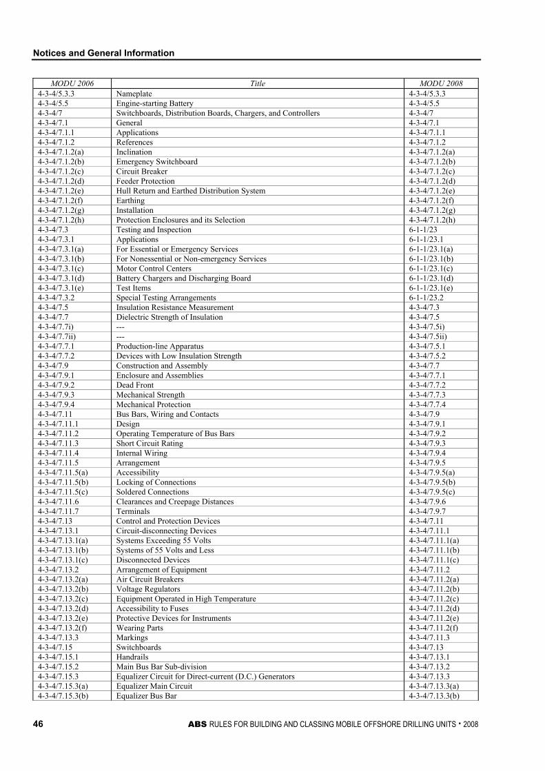
Notices and General Information
46 ABS RULES FOR BUILDING AND CLASSING MOBILE OFFSHORE DRILLING UNITS . 2008
MODU 2006 Title MODU 2008 4-3-4/5.3.3 Nameplate 4-3-4/5.3.3 4-3-4/5.5 Engine-starting Battery 4-3-4/5.5 4-3-4/7 Switchboards, Distribution Boards, Chargers, and Controllers 4-3-4/7 4-3-4/7.1 General 4-3-4/7.1 4-3-4/7.1.1 Applications 4-3-4/7.1.1 4-3-4/7.1.2 References 4-3-4/7.1.2 4-3-4/7.1.2(a) Inclination 4-3-4/7.1.2(a) 4-3-4/7.1.2(b) Emergency Switchboard 4-3-4/7.1.2(b) 4-3-4/7.1.2(c) Circuit Breaker 4-3-4/7.1.2(c) 4-3-4/7.1.2(d) Feeder Protection 4-3-4/7.1.2(d) 4-3-4/7.1.2(e) Hull Return and Earthed Distribution System 4-3-4/7.1.2(e) 4-3-4/7.1.2(f) Earthing 4-3-4/7.1.2(f) 4-3-4/7.1.2(g) Installation 4-3-4/7.1.2(g) 4-3-4/7.1.2(h) Protection Enclosures and its Selection 4-3-4/7.1.2(h) 4-3-4/7.3 Testing and Inspection 6-1-1/23 4-3-4/7.3.1 Applications 6-1-1/23.1 4-3-4/7.3.1(a) For Essential or Emergency Services 6-1-1/23.1(a) 4-3-4/7.3.1(b) For Nonessential or Non-emergency Services 6-1-1/23.1(b) 4-3-4/7.3.1(c) Motor Control Centers 6-1-1/23.1(c) 4-3-4/7.3.1(d) Battery Chargers and Discharging Board 6-1-1/23.1(d) 4-3-4/7.3.1(e) Test Items 6-1-1/23.1(e) 4-3-4/7.3.2 Special Testing Arrangements 6-1-1/23.2 4-3-4/7.5 Insulation Resistance Measurement 4-3-4/7.3 4-3-4/7.7 Dielectric Strength of Insulation 4-3-4/7.5 4-3-4/7.7i) --- 4-3-4/7.5i) 4-3-4/7.7ii) --- 4-3-4/7.5ii) 4-3-4/7.7.1 Production-line Apparatus 4-3-4/7.5.1 4-3-4/7.7.2 Devices with Low Insulation Strength 4-3-4/7.5.2 4-3-4/7.9 Construction and Assembly 4-3-4/7.7 4-3-4/7.9.1 Enclosure and Assemblies 4-3-4/7.7.1 4-3-4/7.9.2 Dead Front 4-3-4/7.7.2 4-3-4/7.9.3 Mechanical Strength 4-3-4/7.7.3 4-3-4/7.9.4 Mechanical Protection 4-3-4/7.7.4 4-3-4/7.11 Bus Bars, Wiring and Contacts 4-3-4/7.9 4-3-4/7.11.1 Design 4-3-4/7.9.1 4-3-4/7.11.2 Operating Temperature of Bus Bars 4-3-4/7.9.2 4-3-4/7.11.3 Short Circuit Rating 4-3-4/7.9.3 4-3-4/7.11.4 Internal Wiring 4-3-4/7.9.4 4-3-4/7.11.5 Arrangement 4-3-4/7.9.5 4-3-4/7.11.5(a) Accessibility 4-3-4/7.9.5(a) 4-3-4/7.11.5(b) Locking of Connections 4-3-4/7.9.5(b) 4-3-4/7.11.5(c) Soldered Connections 4-3-4/7.9.5(c) 4-3-4/7.11.6 Clearances and Creepage Distances 4-3-4/7.9.6 4-3-4/7.11.7 Terminals 4-3-4/7.9.7 4-3-4/7.13 Control and Protection Devices 4-3-4/7.11 4-3-4/7.13.1 Circuit-disconnecting Devices 4-3-4/7.11.1 4-3-4/7.13.1(a) Systems Exceeding 55 Volts 4-3-4/7.11.1(a) 4-3-4/7.13.1(b) Systems of 55 Volts and Less 4-3-4/7.11.1(b) 4-3-4/7.13.1(c) Disconnected Devices 4-3-4/7.11.1(c) 4-3-4/7.13.2 Arrangement of Equipment 4-3-4/7.11.2 4-3-4/7.13.2(a) Air Circuit Breakers 4-3-4/7.11.2(a) 4-3-4/7.13.2(b) Voltage Regulators 4-3-4/7.11.2(b) 4-3-4/7.13.2(c) Equipment Operated in High Temperature 4-3-4/7.11.2(c) 4-3-4/7.13.2(d) Accessibility to Fuses 4-3-4/7.11.2(d) 4-3-4/7.13.2(e) Protective Devices for Instruments 4-3-4/7.11.2(e) 4-3-4/7.13.2(f) Wearing Parts 4-3-4/7.11.2(f) 4-3-4/7.13.3 Markings 4-3-4/7.11.3 4-3-4/7.15 Switchboards 4-3-4/7.13 4-3-4/7.15.1 Handrails 4-3-4/7.13.1 4-3-4/7.15.2 Main Bus Bar Sub-division 4-3-4/7.13.2 4-3-4/7.15.3 Equalizer Circuit for Direct-current (D.C.) Generators 4-3-4/7.13.3 4-3-4/7.15.3(a) Equalizer Main Circuit 4-3-4/7.13.3(a) 4-3-4/7.15.3(b) Equalizer Bus Bar 4-3-4/7.13.3(b)
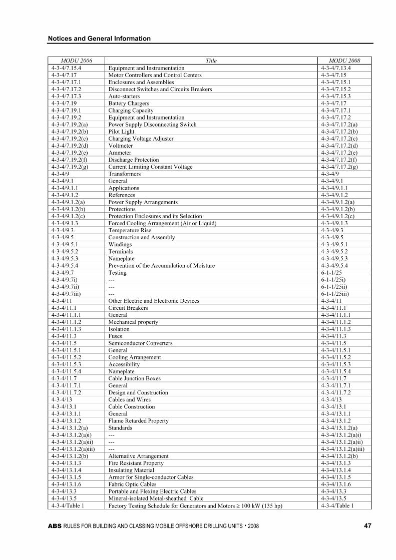
Notices and General Information
ABS RULES FOR BUILDING AND CLASSING MOBILE OFFSHORE DRILLING UNITS . 2008 47
MODU 2006 Title MODU 2008 4-3-4/7.15.4 Equipment and Instrumentation 4-3-4/7.13.4 4-3-4/7.17 Motor Controllers and Control Centers 4-3-4/7.15 4-3-4/7.17.1 Enclosures and Assemblies 4-3-4/7.15.1 4-3-4/7.17.2 Disconnect Switches and Circuits Breakers 4-3-4/7.15.2 4-3-4/7.17.3 Auto-starters 4-3-4/7.15.3 4-3-4/7.19 Battery Chargers 4-3-4/7.17 4-3-4/7.19.1 Charging Capacity 4-3-4/7.17.1 4-3-4/7.19.2 Equipment and Instrumentation 4-3-4/7.17.2 4-3-4/7.19.2(a) Power Supply Disconnecting Switch 4-3-4/7.17.2(a) 4-3-4/7.19.2(b) Pilot Light 4-3-4/7.17.2(b) 4-3-4/7.19.2(c) Charging Voltage Adjuster 4-3-4/7.17.2(c) 4-3-4/7.19.2(d) Voltmeter 4-3-4/7.17.2(d) 4-3-4/7.19.2(e) Ammeter 4-3-4/7.17.2(e) 4-3-4/7.19.2(f) Discharge Protection 4-3-4/7.17.2(f) 4-3-4/7.19.2(g) Current Limiting Constant Voltage 4-3-4/7.17.2(g) 4-3-4/9 Transformers 4-3-4/9 4-3-4/9.1 General 4-3-4/9.1 4-3-4/9.1.1 Applications 4-3-4/9.1.1 4-3-4/9.1.2 References 4-3-4/9.1.2 4-3-4/9.1.2(a) Power Supply Arrangements 4-3-4/9.1.2(a) 4-3-4/9.1.2(b) Protections 4-3-4/9.1.2(b) 4-3-4/9.1.2(c) Protection Enclosures and its Selection 4-3-4/9.1.2(c) 4-3-4/9.1.3 Forced Cooling Arrangement (Air or Liquid) 4-3-4/9.1.3 4-3-4/9.3 Temperature Rise 4-3-4/9.3 4-3-4/9.5 Construction and Assembly 4-3-4/9.5 4-3-4/9.5.1 Windings 4-3-4/9.5.1 4-3-4/9.5.2 Terminals 4-3-4/9.5.2 4-3-4/9.5.3 Nameplate 4-3-4/9.5.3 4-3-4/9.5.4 Prevention of the Accumulation of Moisture 4-3-4/9.5.4 4-3-4/9.7 Testing 6-1-1/25 4-3-4/9.7i) --- 6-1-1/25i) 4-3-4/9.7ii) --- 6-1-1/25ii) 4-3-4/9.7iii) --- 6-1-1/25iii) 4-3-4/11 Other Electric and Electronic Devices 4-3-4/11 4-3-4/11.1 Circuit Breakers 4-3-4/11.1 4-3-4/11.1.1 General 4-3-4/11.1.1 4-3-4/11.1.2 Mechanical property 4-3-4/11.1.2 4-3-4/11.1.3 Isolation 4-3-4/11.1.3 4-3-4/11.3 Fuses 4-3-4/11.3 4-3-4/11.5 Semiconductor Converters 4-3-4/11.5 4-3-4/11.5.1 General 4-3-4/11.5.1 4-3-4/11.5.2 Cooling Arrangement 4-3-4/11.5.2 4-3-4/11.5.3 Accessibility 4-3-4/11.5.3 4-3-4/11.5.4 Nameplate 4-3-4/11.5.4 4-3-4/11.7 Cable Junction Boxes 4-3-4/11.7 4-3-4/11.7.1 General 4-3-4/11.7.1 4-3-4/11.7.2 Design and Construction 4-3-4/11.7.2 4-3-4/13 Cables and Wires 4-3-4/13 4-3-4/13.1 Cable Construction 4-3-4/13.1 4-3-4/13.1.1 General 4-3-4/13.1.1 4-3-4/13.1.2 Flame Retarded Property 4-3-4/13.1.2 4-3-4/13.1.2(a) Standards 4-3-4/13.1.2(a) 4-3-4/13.1.2(a)i) --- 4-3-4/13.1.2(a)i) 4-3-4/13.1.2(a)ii) --- 4-3-4/13.1.2(a)ii) 4-3-4/13.1.2(a)iii) --- 4-3-4/13.1.2(a)iii) 4-3-4/13.1.2(b) Alternative Arrangement 4-3-4/13.1.2(b) 4-3-4/13.1.3 Fire Resistant Property 4-3-4/13.1.3 4-3-4/13.1.4 Insulating Material 4-3-4/13.1.4 4-3-4/13.1.5 Armor for Single-conductor Cables 4-3-4/13.1.5 4-3-4/13.1.6 Fabric Optic Cables 4-3-4/13.1.6 4-3-4/13.3 Portable and Flexing Electric Cables 4-3-4/13.3 4-3-4/13.5 Mineral-isolated Metal-sheathed Cable 4-3-4/13.5 4-3-4/Table 1 Factory Testing Schedule for Generators and Motors ≥ 100 kW (135 hp) 4-3-4/Table 1
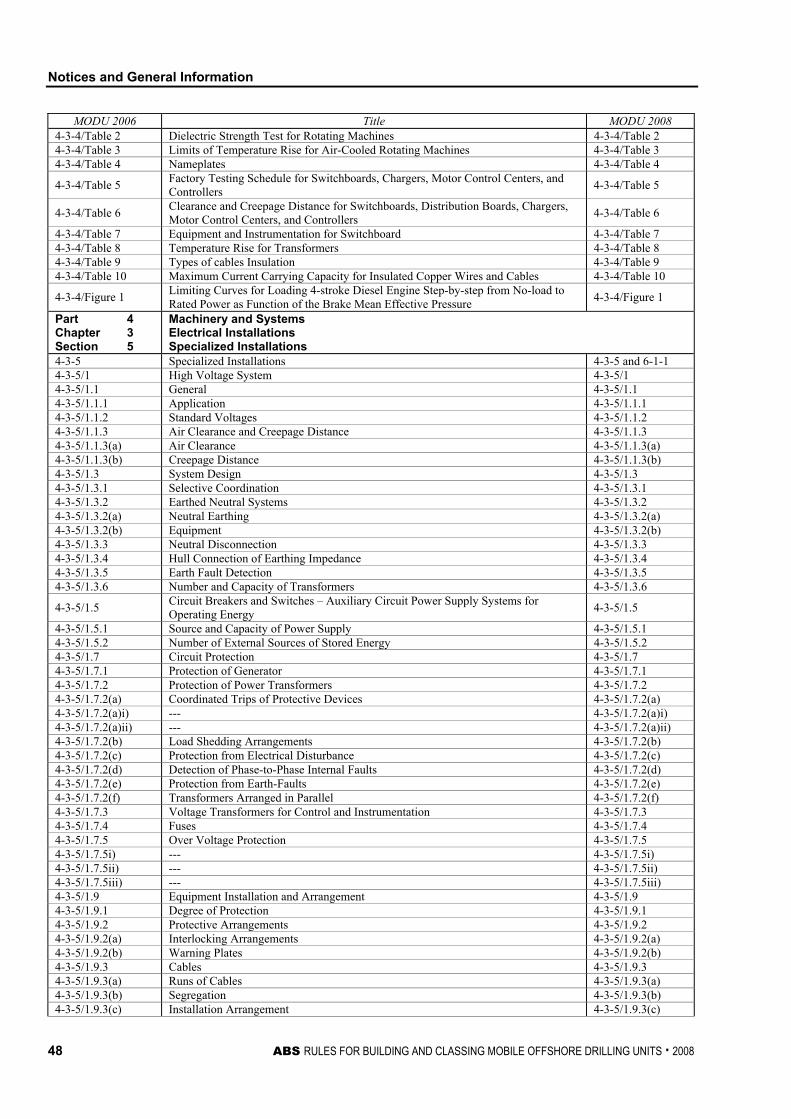
Notices and General Information
48 ABS RULES FOR BUILDING AND CLASSING MOBILE OFFSHORE DRILLING UNITS . 2008
MODU 2006 Title MODU 2008 4-3-4/Table 2 Dielectric Strength Test for Rotating Machines 4-3-4/Table 2 4-3-4/Table 3 Limits of Temperature Rise for Air-Cooled Rotating Machines 4-3-4/Table 3 4-3-4/Table 4 Nameplates 4-3-4/Table 4
4-3-4/Table 5 Factory Testing Schedule for Switchboards, Chargers, Motor Control Centers, and Controllers 4-3-4/Table 5
4-3-4/Table 6 Clearance and Creepage Distance for Switchboards, Distribution Boards, Chargers, Motor Control Centers, and Controllers 4-3-4/Table 6
4-3-4/Table 7 Equipment and Instrumentation for Switchboard 4-3-4/Table 7 4-3-4/Table 8 Temperature Rise for Transformers 4-3-4/Table 8 4-3-4/Table 9 Types of cables Insulation 4-3-4/Table 9 4-3-4/Table 10 Maximum Current Carrying Capacity for Insulated Copper Wires and Cables 4-3-4/Table 10
4-3-4/Figure 1 Limiting Curves for Loading 4-stroke Diesel Engine Step-by-step from No-load to Rated Power as Function of the Brake Mean Effective Pressure 4-3-4/Figure 1
Part 4 Chapter 3 Section 5
Machinery and Systems Electrical Installations Specialized Installations
4-3-5 Specialized Installations 4-3-5 and 6-1-1 4-3-5/1 High Voltage System 4-3-5/1 4-3-5/1.1 General 4-3-5/1.1 4-3-5/1.1.1 Application 4-3-5/1.1.1 4-3-5/1.1.2 Standard Voltages 4-3-5/1.1.2 4-3-5/1.1.3 Air Clearance and Creepage Distance 4-3-5/1.1.3 4-3-5/1.1.3(a) Air Clearance 4-3-5/1.1.3(a) 4-3-5/1.1.3(b) Creepage Distance 4-3-5/1.1.3(b) 4-3-5/1.3 System Design 4-3-5/1.3 4-3-5/1.3.1 Selective Coordination 4-3-5/1.3.1 4-3-5/1.3.2 Earthed Neutral Systems 4-3-5/1.3.2 4-3-5/1.3.2(a) Neutral Earthing 4-3-5/1.3.2(a) 4-3-5/1.3.2(b) Equipment 4-3-5/1.3.2(b) 4-3-5/1.3.3 Neutral Disconnection 4-3-5/1.3.3 4-3-5/1.3.4 Hull Connection of Earthing Impedance 4-3-5/1.3.4 4-3-5/1.3.5 Earth Fault Detection 4-3-5/1.3.5 4-3-5/1.3.6 Number and Capacity of Transformers 4-3-5/1.3.6
4-3-5/1.5 Circuit Breakers and Switches – Auxiliary Circuit Power Supply Systems for Operating Energy 4-3-5/1.5
4-3-5/1.5.1 Source and Capacity of Power Supply 4-3-5/1.5.1 4-3-5/1.5.2 Number of External Sources of Stored Energy 4-3-5/1.5.2 4-3-5/1.7 Circuit Protection 4-3-5/1.7 4-3-5/1.7.1 Protection of Generator 4-3-5/1.7.1 4-3-5/1.7.2 Protection of Power Transformers 4-3-5/1.7.2 4-3-5/1.7.2(a) Coordinated Trips of Protective Devices 4-3-5/1.7.2(a) 4-3-5/1.7.2(a)i) --- 4-3-5/1.7.2(a)i) 4-3-5/1.7.2(a)ii) --- 4-3-5/1.7.2(a)ii) 4-3-5/1.7.2(b) Load Shedding Arrangements 4-3-5/1.7.2(b) 4-3-5/1.7.2(c) Protection from Electrical Disturbance 4-3-5/1.7.2(c) 4-3-5/1.7.2(d) Detection of Phase-to-Phase Internal Faults 4-3-5/1.7.2(d) 4-3-5/1.7.2(e) Protection from Earth-Faults 4-3-5/1.7.2(e) 4-3-5/1.7.2(f) Transformers Arranged in Parallel 4-3-5/1.7.2(f) 4-3-5/1.7.3 Voltage Transformers for Control and Instrumentation 4-3-5/1.7.3 4-3-5/1.7.4 Fuses 4-3-5/1.7.4 4-3-5/1.7.5 Over Voltage Protection 4-3-5/1.7.5 4-3-5/1.7.5i) --- 4-3-5/1.7.5i) 4-3-5/1.7.5ii) --- 4-3-5/1.7.5ii) 4-3-5/1.7.5iii) --- 4-3-5/1.7.5iii) 4-3-5/1.9 Equipment Installation and Arrangement 4-3-5/1.9 4-3-5/1.9.1 Degree of Protection 4-3-5/1.9.1 4-3-5/1.9.2 Protective Arrangements 4-3-5/1.9.2 4-3-5/1.9.2(a) Interlocking Arrangements 4-3-5/1.9.2(a) 4-3-5/1.9.2(b) Warning Plates 4-3-5/1.9.2(b) 4-3-5/1.9.3 Cables 4-3-5/1.9.3 4-3-5/1.9.3(a) Runs of Cables 4-3-5/1.9.3(a) 4-3-5/1.9.3(b) Segregation 4-3-5/1.9.3(b) 4-3-5/1.9.3(c) Installation Arrangement 4-3-5/1.9.3(c)
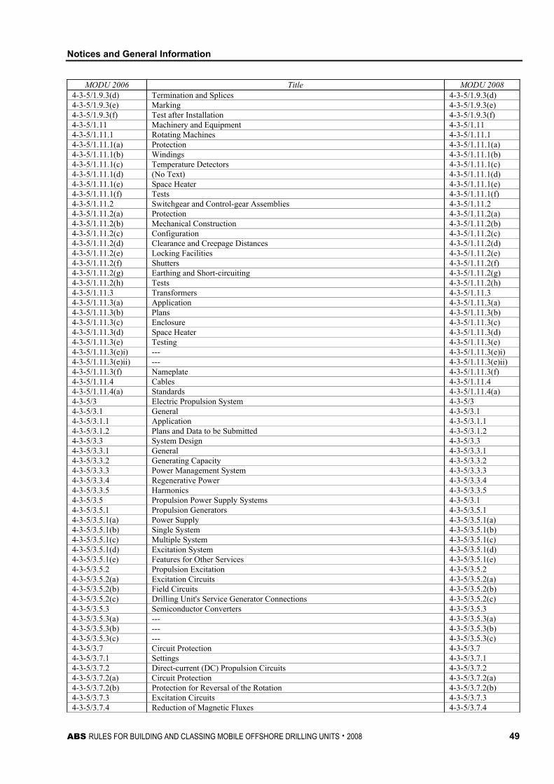
Notices and General Information
ABS RULES FOR BUILDING AND CLASSING MOBILE OFFSHORE DRILLING UNITS . 2008 49
MODU 2006 Title MODU 2008 4-3-5/1.9.3(d) Termination and Splices 4-3-5/1.9.3(d) 4-3-5/1.9.3(e) Marking 4-3-5/1.9.3(e) 4-3-5/1.9.3(f) Test after Installation 4-3-5/1.9.3(f) 4-3-5/1.11 Machinery and Equipment 4-3-5/1.11 4-3-5/1.11.1 Rotating Machines 4-3-5/1.11.1 4-3-5/1.11.1(a) Protection 4-3-5/1.11.1(a) 4-3-5/1.11.1(b) Windings 4-3-5/1.11.1(b) 4-3-5/1.11.1(c) Temperature Detectors 4-3-5/1.11.1(c) 4-3-5/1.11.1(d) (No Text) 4-3-5/1.11.1(d) 4-3-5/1.11.1(e) Space Heater 4-3-5/1.11.1(e) 4-3-5/1.11.1(f) Tests 4-3-5/1.11.1(f) 4-3-5/1.11.2 Switchgear and Control-gear Assemblies 4-3-5/1.11.2 4-3-5/1.11.2(a) Protection 4-3-5/1.11.2(a) 4-3-5/1.11.2(b) Mechanical Construction 4-3-5/1.11.2(b) 4-3-5/1.11.2(c) Configuration 4-3-5/1.11.2(c) 4-3-5/1.11.2(d) Clearance and Creepage Distances 4-3-5/1.11.2(d) 4-3-5/1.11.2(e) Locking Facilities 4-3-5/1.11.2(e) 4-3-5/1.11.2(f) Shutters 4-3-5/1.11.2(f) 4-3-5/1.11.2(g) Earthing and Short-circuiting 4-3-5/1.11.2(g) 4-3-5/1.11.2(h) Tests 4-3-5/1.11.2(h) 4-3-5/1.11.3 Transformers 4-3-5/1.11.3 4-3-5/1.11.3(a) Application 4-3-5/1.11.3(a) 4-3-5/1.11.3(b) Plans 4-3-5/1.11.3(b) 4-3-5/1.11.3(c) Enclosure 4-3-5/1.11.3(c) 4-3-5/1.11.3(d) Space Heater 4-3-5/1.11.3(d) 4-3-5/1.11.3(e) Testing 4-3-5/1.11.3(e) 4-3-5/1.11.3(e)i) --- 4-3-5/1.11.3(e)i) 4-3-5/1.11.3(e)ii) --- 4-3-5/1.11.3(e)ii) 4-3-5/1.11.3(f) Nameplate 4-3-5/1.11.3(f) 4-3-5/1.11.4 Cables 4-3-5/1.11.4 4-3-5/1.11.4(a) Standards 4-3-5/1.11.4(a) 4-3-5/3 Electric Propulsion System 4-3-5/3 4-3-5/3.1 General 4-3-5/3.1 4-3-5/3.1.1 Application 4-3-5/3.1.1 4-3-5/3.1.2 Plans and Data to be Submitted 4-3-5/3.1.2 4-3-5/3.3 System Design 4-3-5/3.3 4-3-5/3.3.1 General 4-3-5/3.3.1 4-3-5/3.3.2 Generating Capacity 4-3-5/3.3.2 4-3-5/3.3.3 Power Management System 4-3-5/3.3.3 4-3-5/3.3.4 Regenerative Power 4-3-5/3.3.4 4-3-5/3.3.5 Harmonics 4-3-5/3.3.5 4-3-5/3.5 Propulsion Power Supply Systems 4-3-5/3.1 4-3-5/3.5.1 Propulsion Generators 4-3-5/3.5.1 4-3-5/3.5.1(a) Power Supply 4-3-5/3.5.1(a) 4-3-5/3.5.1(b) Single System 4-3-5/3.5.1(b) 4-3-5/3.5.1(c) Multiple System 4-3-5/3.5.1(c) 4-3-5/3.5.1(d) Excitation System 4-3-5/3.5.1(d) 4-3-5/3.5.1(e) Features for Other Services 4-3-5/3.5.1(e) 4-3-5/3.5.2 Propulsion Excitation 4-3-5/3.5.2 4-3-5/3.5.2(a) Excitation Circuits 4-3-5/3.5.2(a) 4-3-5/3.5.2(b) Field Circuits 4-3-5/3.5.2(b) 4-3-5/3.5.2(c) Drilling Unit's Service Generator Connections 4-3-5/3.5.2(c) 4-3-5/3.5.3 Semiconductor Converters 4-3-5/3.5.3 4-3-5/3.5.3(a) --- 4-3-5/3.5.3(a) 4-3-5/3.5.3(b) --- 4-3-5/3.5.3(b) 4-3-5/3.5.3(c) --- 4-3-5/3.5.3(c) 4-3-5/3.7 Circuit Protection 4-3-5/3.7 4-3-5/3.7.1 Settings 4-3-5/3.7.1 4-3-5/3.7.2 Direct-current (DC) Propulsion Circuits 4-3-5/3.7.2 4-3-5/3.7.2(a) Circuit Protection 4-3-5/3.7.2(a) 4-3-5/3.7.2(b) Protection for Reversal of the Rotation 4-3-5/3.7.2(b) 4-3-5/3.7.3 Excitation Circuits 4-3-5/3.7.3 4-3-5/3.7.4 Reduction of Magnetic Fluxes 4-3-5/3.7.4
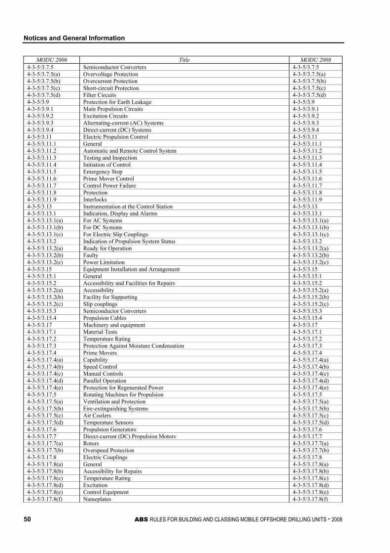
Notices and General Information
50 ABS RULES FOR BUILDING AND CLASSING MOBILE OFFSHORE DRILLING UNITS . 2008
MODU 2006 Title MODU 2008 4-3-5/3.7.5 Semiconductor Converters 4-3-5/3.7.5 4-3-5/3.7.5(a) Overvoltage Protection 4-3-5/3.7.5(a) 4-3-5/3.7.5(b) Overcurrent Protection 4-3-5/3.7.5(b) 4-3-5/3.7.5(c) Short-circuit Protection 4-3-5/3.7.5(c) 4-3-5/3.7.5(d) Filter Circuits 4-3-5/3.7.5(d) 4-3-5/3.9 Protection for Earth Leakage 4-3-5/3.9 4-3-5/3.9.1 Main Propulsion Circuits 4-3-5/3.9.1 4-3-5/3.9.2 Excitation Circuits 4-3-5/3.9.2 4-3-5/3.9.3 Alternating-current (AC) Systems 4-3-5/3.9.3 4-3-5/3.9.4 Direct-current (DC) Systems 4-3-5/3.9.4 4-3-5/3.11 Electric Propulsion Control 4-3-5/3.11 4-3-5/3.11.1 General 4-3-5/3.11.1 4-3-5/3.11.2 Automatic and Remote Control System 4-3-5/3.11.2 4-3-5/3.11.3 Testing and Inspection 4-3-5/3.11.3 4-3-5/3.11.4 Initiation of Control 4-3-5/3.11.4 4-3-5/3.11.5 Emergency Stop 4-3-5/3.11.5 4-3-5/3.11.6 Prime Mover Control 4-3-5/3.11.6 4-3-5/3.11.7 Control Power Failure 4-3-5/3.11.7 4-3-5/3.11.8 Protection 4-3-5/3.11.8 4-3-5/3.11.9 Interlocks 4-3-5/3.11.9 4-3-5/3.13 Instrumentation at the Control Station 4-3-5/3.13 4-3-5/3.13.1 Indication, Display and Alarms 4-3-5/3.13.1 4-3-5/3.13.1(a) For AC Systems 4-3-5/3.13.1(a) 4-3-5/3.13.1(b) For DC Systems 4-3-5/3.13.1(b) 4-3-5/3.13.1(c) For Electric Slip Couplings 4-3-5/3.13.1(c) 4-3-5/3.13.2 Indication of Propulsion System Status 4-3-5/3.13.2 4-3-5/3.13.2(a) Ready for Operation 4-3-5/3.13.2(a) 4-3-5/3.13.2(b) Faulty 4-3-5/3.13.2(b) 4-3-5/3.13.2(c) Power Limitation 4-3-5/3.13.2(c) 4-3-5/3.15 Equipment Installation and Arrangement 4-3-5/3.15 4-3-5/3.15.1 General 4-3-5/3.15.1 4-3-5/3.15.2 Accessibility and Facilities for Repairs 4-3-5/3.15.2 4-3-5/3.15.2(a) Accessibility 4-3-5/3.15.2(a) 4-3-5/3.15.2(b) Facility for Supporting 4-3-5/3.15.2(b) 4-3-5/3.15.2(c) Slip couplings 4-3-5/3.15.2(c) 4-3-5/3.15.3 Semiconductor Converters 4-3-5/3.15.3 4-3-5/3.15.4 Propulsion Cables 4-3-5/3.15.4 4-3-5/3.17 Machinery and equipment 4-3-5/3.17 4-3-5/3.17.1 Material Tests 4-3-5/3.17.1 4-3-5/3.17.2 Temperature Rating 4-3-5/3.17.2 4-3-5/3.17.3 Protection Against Moisture Condensation 4-3-5/3.17.3 4-3-5/3.17.4 Prime Movers 4-3-5/3.17.4 4-3-5/3.17.4(a) Capability 4-3-5/3.17.4(a) 4-3-5/3.17.4(b) Speed Control 4-3-5/3.17.4(b) 4-3-5/3.17.4(c) Manual Controls 4-3-5/3.17.4(c) 4-3-5/3.17.4(d) Parallel Operation 4-3-5/3.17.4(d) 4-3-5/3.17.4(e) Protection for Regenerated Power 4-3-5/3.17.4(e) 4-3-5/3.17.5 Rotating Machines for Propulsion 4-3-5/3.17.5 4-3-5/3.17.5(a) Ventilation and Protection 4-3-5/3.17.5(a) 4-3-5/3.17.5(b) Fire-extinguishing Systems 4-3-5/3.17.5(b) 4-3-5/3.17.5(c) Air Coolers 4-3-5/3.17.5(c) 4-3-5/3.17.5(d) Temperature Sensors 4-3-5/3.17.5(d) 4-3-5/3.17.6 Propulsion Generators 4-3-5/3.17.6 4-3-5/3.17.7 Direct-current (DC) Propulsion Motors 4-3-5/3.17.7 4-3-5/3.17.7(a) Rotors 4-3-5/3.17.7(a) 4-3-5/3.17.7(b) Overspeed Protection 4-3-5/3.17.7(b) 4-3-5/3.17.8 Electric Couplings 4-3-5/3.17.8 4-3-5/3.17.8(a) General 4-3-5/3.17.8(a) 4-3-5/3.17.8(b) Accessibility for Repairs 4-3-5/3.17.8(b) 4-3-5/3.17.8(c) Temperature Rating 4-3-5/3.17.8(c) 4-3-5/3.17.8(d) Excitation 4-3-5/3.17.8(d) 4-3-5/3.17.8(e) Control Equipment 4-3-5/3.17.8(e) 4-3-5/3.17.8(f) Nameplates 4-3-5/3.17.8(f)
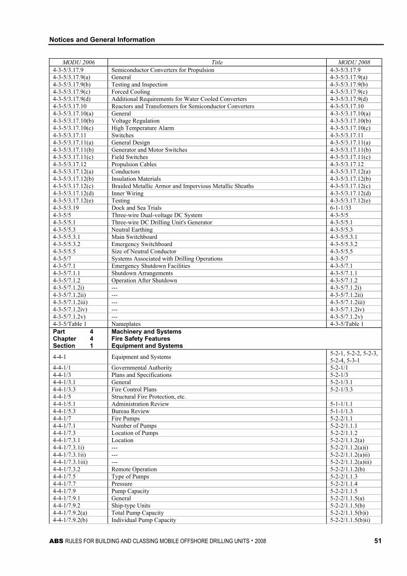
Notices and General Information
ABS RULES FOR BUILDING AND CLASSING MOBILE OFFSHORE DRILLING UNITS . 2008 51
MODU 2006 Title MODU 2008 4-3-5/3.17.9 Semiconductor Converters for Propulsion 4-3-5/3.17.9 4-3-5/3.17.9(a) General 4-3-5/3.17.9(a) 4-3-5/3.17.9(b) Testing and Inspection 4-3-5/3.17.9(b) 4-3-5/3.17.9(c) Forced Cooling 4-3-5/3.17.9(c) 4-3-5/3.17.9(d) Additional Requirements for Water Cooled Converters 4-3-5/3.17.9(d) 4-3-5/3.17.10 Reactors and Transformers for Semiconductor Converters 4-3-5/3.17.10 4-3-5/3.17.10(a) General 4-3-5/3.17.10(a) 4-3-5/3.17.10(b) Voltage Regulation 4-3-5/3.17.10(b) 4-3-5/3.17.10(c) High Temperature Alarm 4-3-5/3.17.10(c) 4-3-5/3.17.11 Switches 4-3-5/3.17.11 4-3-5/3.17.11(a) General Design 4-3-5/3.17.11(a) 4-3-5/3.17.11(b) Generator and Motor Switches 4-3-5/3.17.11(b) 4-3-5/3.17.11(c) Field Switches 4-3-5/3.17.11(c) 4-3-5/3.17.12 Propulsion Cables 4-3-5/3.17.12 4-3-5/3.17.12(a) Conductors 4-3-5/3.17.12(a) 4-3-5/3.17.12(b) Insulation Materials 4-3-5/3.17.12(b) 4-3-5/3.17.12(c) Braided Metallic Armor and Impervious Metallic Sheaths 4-3-5/3.17.12(c) 4-3-5/3.17.12(d) Inner Wiring 4-3-5/3.17.12(d) 4-3-5/3.17.12(e) Testing 4-3-5/3.17.12(e) 4-3-5/3.19 Dock and Sea Trials 6-1-1/33 4-3-5/5 Three-wire Dual-voltage DC System 4-3-5/5 4-3-5/5.1 Three-wire DC Drilling Unit's Generator 4-3-5/5.1 4-3-5/5.3 Neutral Earthing 4-3-5/5.3 4-3-5/5.3.1 Main Switchboard 4-3-5/5.3.1 4-3-5/5.3.2 Emergency Switchboard 4-3-5/5.3.2 4-3-5/5.5 Size of Neutral Conductor 4-3-5/5.5 4-3-5/7 Systems Associated with Drilling Operations 4-3-5/7 4-3-5/7.1 Emergency Shutdown Facilities 4-3-5/7.1 4-3-5/7.1.1 Shutdown Arrangements 4-3-5/7.1.1 4-3-5/7.1.2 Operation After Shutdown 4-3-5/7.1.2 4-3-5/7.1.2i) --- 4-3-5/7.1.2i) 4-3-5/7.1.2ii) --- 4-3-5/7.1.2ii) 4-3-5/7.1.2iii) --- 4-3-5/7.1.2iii) 4-3-5/7.1.2iv) --- 4-3-5/7.1.2iv) 4-3-5/7.1.2v) --- 4-3-5/7.1.2v) 4-3-5/Table 1 Nameplates 4-3-5/Table 1 Part 4 Chapter 4 Section 1
Machinery and Systems Fire Safety Features Equipment and Systems
4-4-1 Equipment and Systems 5-2-1, 5-2-2, 5-2-3, 5-2-4, 5-3-1
4-4-1/1 Governmental Authority 5-2-1/1 4-4-1/3 Plans and Specifications 5-2-1/3 4-4-1/3.1 General 5-2-1/3.1 4-4-1/3.3 Fire Control Plans 5-2-1/3.3 4-4-1/5 Structural Fire Protection, etc. 4-4-1/5.1 Administration Review 5-1-1/1.1 4-4-1/5.3 Bureau Review 5-1-1/1.3 4-4-1/7 Fire Pumps 5-2-2/1.1 4-4-1/7.1 Number of Pumps 5-2-2/1.1.1 4-4-1/7.3 Location of Pumps 5-2-2/1.1.2 4-4-1/7.3.1 Location 5-2-2/1.1.2(a) 4-4-1/7.3.1i) --- 5-2-2/1.1.2(a)i) 4-4-1/7.3.1ii) --- 5-2-2/1.1.2(a)ii) 4-4-1/7.3.1iii) --- 5-2-2/1.1.2(a)iii) 4-4-1/7.3.2 Remote Operation 5-2-2/1.1.2(b) 4-4-1/7.5 Type of Pumps 5-2-2/1.1.3 4-4-1/7.7 Pressure 5-2-2/1.1.4 4-4-1/7.9 Pump Capacity 5-2-2/1.1.5 4-4-1/7.9.1 General 5-2-2/1.1.5(a) 4-4-1/7.9.2 Ship-type Units 5-2-2/1.1.5(b) 4-4-1/7.9.2(a) Total Pump Capacity 5-2-2/1.1.5(b)i) 4-4-1/7.9.2(b) Individual Pump Capacity 5-2-2/1.1.5(b)ii)
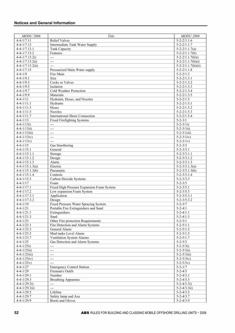
Notices and General Information
52 ABS RULES FOR BUILDING AND CLASSING MOBILE OFFSHORE DRILLING UNITS . 2008
MODU 2006 Title MODU 2008 4-4-1/7.11 Relief Valves 5-2-2/1.1.6 4-4-1/7.13 Intermediate Tank Water Supply 5-2-2/1.1.7 4-4-1/7.13.1 Tank Capacity 5-2-2/1.1.7(a) 4-4-1/7.13.2 Features 5-2-2/1.1.7(b) 4-4-1/7.13.2i) --- 5-2-2/1.1.7(b)i) 4-4-1/7.13.2ii) --- 5-2-2/1.1.7(b)ii) 4-4-1/7.13.2iii) --- 5-2-2/1.1.7(b)iii) 4-4-1/7.15 Pressurized Main Water supply 5-2-2/1.1.8 4-4-1/9 Fire Main 5-2-2/1.3 4-4-1/9.1 Size 5-2-2/1.3.1 4-4-1/9.3 Cocks or Valves 5-2-2/1.3.2 4-4-1/9.5 Isolation 5-2-2/1.3.3 4-4-1/9.7 Cold Weather Protection 5-2-2/1.3.4 4-4-1/9.9 Materials 5-2-2/1.3.5 4-4-1/11 Hydrants, Hoses, and Nozzles 5-2-2/1.5 4-4-1/11.1 Hydrants 5-2-2/1.5.1 4-4-1/11.3 Hoses 5-2-2/1.5.2 4-4-1/11.5 Nozzles 5-2-2/1.5.3 4-4-1/11.7 International Shore Connection 5-2-2/1.5.4 4-4-1/13 Fixed Firefighting Systems 5-2-3/1 4-4-1/13i) --- 5-2-3/1i) 4-4-1/13ii) --- 5-2-3/1ii) 4-4-1/13iii) --- 5-2-3/1iii) 4-4-1/13iv) --- 5-2-3/1iv) 4-4-1/13v) --- 5-2-3/1v) 4-4-1/15 Gas Smothering 5-2-3/3 4-4-1/15.1 General 5-2-3/3.1 4-4-1/15.1.1 Storage 5-2-3/3.1.1 4-4-1/15.1.2 Design 5-2-3/3.1.2 4-4-1/15.1.3 Alarm 5-2-3/3.1.3 4-4-1/15.1.3(a) Electric 5-2-3/3.1.3(a) 4-4-1/15.1.3(b) Pneumatic 5-2-3/3.1.3(b) 4-4-1/15.1.4 Controls 5-2-3/3.1.4 4-4-1/15.3 Carbon Dioxide Systems 5-2-3/3.3 4-4-1/17 Foam 5-2-3/5 4-4-1/17.1 Fixed High Pressure Expansion Foam System 5-2-3/5.1 4-4-1/17.2 Low expansion Foam System 5-2-3/5.3 4-4-1/17.3.1 Application 5-2-3/5.3.1 4-4-1/17.3.2 Design 5-2-3/5.3.2 4-4-1/19 Fixed Pressure Water Spraying System 5-2-3/7 4-4-1/21 Portable Fire Extinguishers and Sand 5-2-4/1 4-4-1/21.1 Extinguishers 5-2-4/1.1 4-4-1/21.3 Sand 5-2-4/1.3 4-4-1/23 Other Fire protection Requirements 5-2-5/1 4-4-1/23.1 Fire Detection and Alarm Systems 5-2-5/1.1 4-4-1/23.3 General Alarm 5-2-5/1.3 4-4-1/23.5 Mud tanks Level Alarm 5-2-5/1.5 4-4-1/23.7 Ventilation System Alarms 5-2-5/1.7 4-4-1/25 Gas Detection and Alarm Systems 5-2-5/3 4-4-1/25i) --- 5-2-5/3i) 4-4-1/25ii) --- 5-2-5/3ii) 4-4-1/25iii) --- 5-2-5/3iii) 4-4-1/25iv) --- 5-2-5/3iv) 4-4-1/25v) --- 5-2-5/3v) 4-4-1/27 Emergency Control Station 5-3-1/7 4-4-1/29 Fireman's Outfit 5-2-4/3 4-4-1/29.1 Number 5-2-4/3.1 4-4-1/29.3 Breathing Apparatus 5-2-4/3.3 4-4-1/29.3i) --- 5-2-4/3.3i) 4-4-1/29.3ii) --- 5-2-4/3.3ii) 4-4-1/29.5 Lifeline 5-2-4/3.5 4-4-1/29.7 Safety lamp and Axe 5-2-4/3.7 4-4-1/29.9 Boots and Gloves 5-2-4/3.9
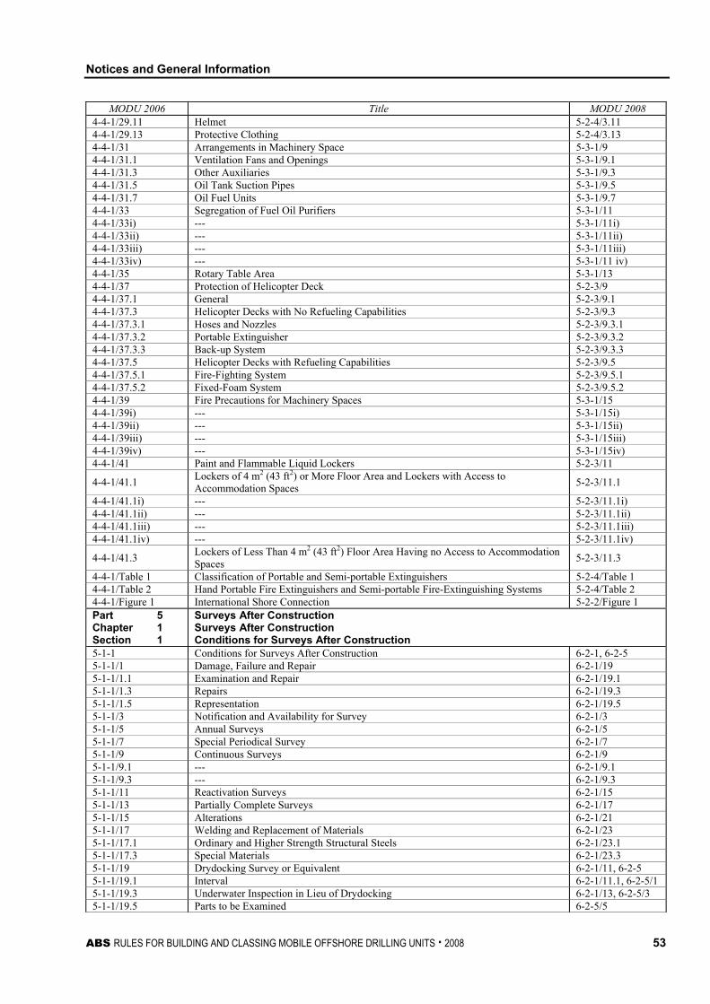
Notices and General Information
ABS RULES FOR BUILDING AND CLASSING MOBILE OFFSHORE DRILLING UNITS . 2008 53
MODU 2006 Title MODU 2008 4-4-1/29.11 Helmet 5-2-4/3.11 4-4-1/29.13 Protective Clothing 5-2-4/3.13 4-4-1/31 Arrangements in Machinery Space 5-3-1/9 4-4-1/31.1 Ventilation Fans and Openings 5-3-1/9.1 4-4-1/31.3 Other Auxiliaries 5-3-1/9.3 4-4-1/31.5 Oil Tank Suction Pipes 5-3-1/9.5 4-4-1/31.7 Oil Fuel Units 5-3-1/9.7 4-4-1/33 Segregation of Fuel Oil Purifiers 5-3-1/11 4-4-1/33i) --- 5-3-1/11i) 4-4-1/33ii) --- 5-3-1/11ii) 4-4-1/33iii) --- 5-3-1/11iii) 4-4-1/33iv) --- 5-3-1/11 iv) 4-4-1/35 Rotary Table Area 5-3-1/13 4-4-1/37 Protection of Helicopter Deck 5-2-3/9 4-4-1/37.1 General 5-2-3/9.1 4-4-1/37.3 Helicopter Decks with No Refueling Capabilities 5-2-3/9.3 4-4-1/37.3.1 Hoses and Nozzles 5-2-3/9.3.1 4-4-1/37.3.2 Portable Extinguisher 5-2-3/9.3.2 4-4-1/37.3.3 Back-up System 5-2-3/9.3.3 4-4-1/37.5 Helicopter Decks with Refueling Capabilities 5-2-3/9.5 4-4-1/37.5.1 Fire-Fighting System 5-2-3/9.5.1 4-4-1/37.5.2 Fixed-Foam System 5-2-3/9.5.2 4-4-1/39 Fire Precautions for Machinery Spaces 5-3-1/15 4-4-1/39i) --- 5-3-1/15i) 4-4-1/39ii) --- 5-3-1/15ii) 4-4-1/39iii) --- 5-3-1/15iii) 4-4-1/39iv) --- 5-3-1/15iv) 4-4-1/41 Paint and Flammable Liquid Lockers 5-2-3/11
4-4-1/41.1 Lockers of 4 m2 (43 ft2) or More Floor Area and Lockers with Access to Accommodation Spaces 5-2-3/11.1
4-4-1/41.1i) --- 5-2-3/11.1i) 4-4-1/41.1ii) --- 5-2-3/11.1ii) 4-4-1/41.1iii) --- 5-2-3/11.1iii) 4-4-1/41.1iv) --- 5-2-3/11.1iv)
4-4-1/41.3 Lockers of Less Than 4 m2 (43 ft2) Floor Area Having no Access to Accommodation Spaces 5-2-3/11.3
4-4-1/Table 1 Classification of Portable and Semi-portable Extinguishers 5-2-4/Table 1 4-4-1/Table 2 Hand Portable Fire Extinguishers and Semi-portable Fire-Extinguishing Systems 5-2-4/Table 2 4-4-1/Figure 1 International Shore Connection 5-2-2/Figure 1 Part 5 Chapter 1 Section 1
Surveys After Construction Surveys After Construction Conditions for Surveys After Construction
5-1-1 Conditions for Surveys After Construction 6-2-1, 6-2-5 5-1-1/1 Damage, Failure and Repair 6-2-1/19 5-1-1/1.1 Examination and Repair 6-2-1/19.1 5-1-1/1.3 Repairs 6-2-1/19.3 5-1-1/1.5 Representation 6-2-1/19.5 5-1-1/3 Notification and Availability for Survey 6-2-1/3 5-1-1/5 Annual Surveys 6-2-1/5 5-1-1/7 Special Periodical Survey 6-2-1/7 5-1-1/9 Continuous Surveys 6-2-1/9 5-1-1/9.1 --- 6-2-1/9.1 5-1-1/9.3 --- 6-2-1/9.3 5-1-1/11 Reactivation Surveys 6-2-1/15 5-1-1/13 Partially Complete Surveys 6-2-1/17 5-1-1/15 Alterations 6-2-1/21 5-1-1/17 Welding and Replacement of Materials 6-2-1/23 5-1-1/17.1 Ordinary and Higher Strength Structural Steels 6-2-1/23.1 5-1-1/17.3 Special Materials 6-2-1/23.3 5-1-1/19 Drydocking Survey or Equivalent 6-2-1/11, 6-2-5 5-1-1/19.1 Interval 6-2-1/11.1, 6-2-5/1 5-1-1/19.3 Underwater Inspection in Lieu of Drydocking 6-2-1/13, 6-2-5/3 5-1-1/19.5 Parts to be Examined 6-2-5/5
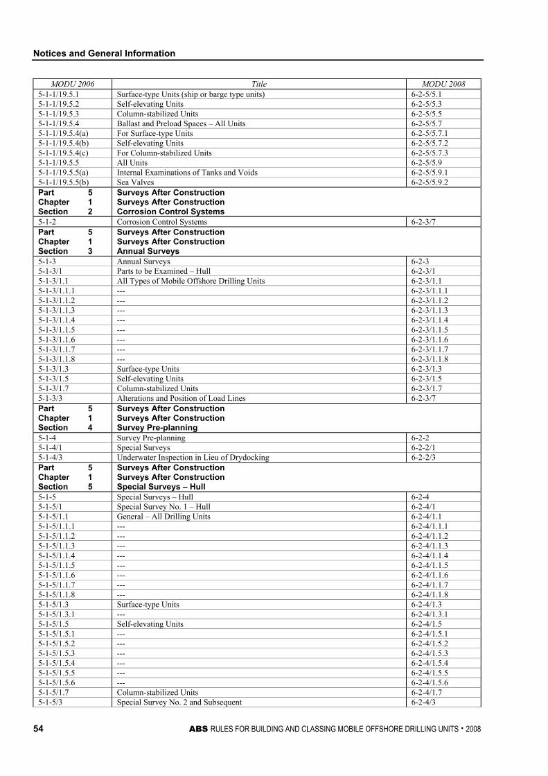
Notices and General Information
54 ABS RULES FOR BUILDING AND CLASSING MOBILE OFFSHORE DRILLING UNITS . 2008
MODU 2006 Title MODU 2008 5-1-1/19.5.1 Surface-type Units (ship or barge type units) 6-2-5/5.1 5-1-1/19.5.2 Self-elevating Units 6-2-5/5.3 5-1-1/19.5.3 Column-stabilized Units 6-2-5/5.5 5-1-1/19.5.4 Ballast and Preload Spaces – All Units 6-2-5/5.7 5-1-1/19.5.4(a) For Surface-type Units 6-2-5/5.7.1 5-1-1/19.5.4(b) Self-elevating Units 6-2-5/5.7.2 5-1-1/19.5.4(c) For Column-stabilized Units 6-2-5/5.7.3 5-1-1/19.5.5 All Units 6-2-5/5.9 5-1-1/19.5.5(a) Internal Examinations of Tanks and Voids 6-2-5/5.9.1 5-1-1/19.5.5(b) Sea Valves 6-2-5/5.9.2 Part 5 Chapter 1 Section 2
Surveys After Construction Surveys After Construction Corrosion Control Systems
5-1-2 Corrosion Control Systems 6-2-3/7 Part 5 Chapter 1 Section 3
Surveys After Construction Surveys After Construction Annual Surveys
5-1-3 Annual Surveys 6-2-3 5-1-3/1 Parts to be Examined – Hull 6-2-3/1 5-1-3/1.1 All Types of Mobile Offshore Drilling Units 6-2-3/1.1 5-1-3/1.1.1 --- 6-2-3/1.1.1 5-1-3/1.1.2 --- 6-2-3/1.1.2 5-1-3/1.1.3 --- 6-2-3/1.1.3 5-1-3/1.1.4 --- 6-2-3/1.1.4 5-1-3/1.1.5 --- 6-2-3/1.1.5 5-1-3/1.1.6 --- 6-2-3/1.1.6 5-1-3/1.1.7 --- 6-2-3/1.1.7 5-1-3/1.1.8 --- 6-2-3/1.1.8 5-1-3/1.3 Surface-type Units 6-2-3/1.3 5-1-3/1.5 Self-elevating Units 6-2-3/1.5 5-1-3/1.7 Column-stabilized Units 6-2-3/1.7 5-1-3/3 Alterations and Position of Load Lines 6-2-3/7 Part 5 Chapter 1 Section 4
Surveys After Construction Surveys After Construction Survey Pre-planning
5-1-4 Survey Pre-planning 6-2-2 5-1-4/1 Special Surveys 6-2-2/1 5-1-4/3 Underwater Inspection in Lieu of Drydocking 6-2-2/3 Part 5 Chapter 1 Section 5
Surveys After Construction Surveys After Construction Special Surveys – Hull
5-1-5 Special Surveys – Hull 6-2-4 5-1-5/1 Special Survey No. 1 – Hull 6-2-4/1 5-1-5/1.1 General – All Drilling Units 6-2-4/1.1 5-1-5/1.1.1 --- 6-2-4/1.1.1 5-1-5/1.1.2 --- 6-2-4/1.1.2 5-1-5/1.1.3 --- 6-2-4/1.1.3 5-1-5/1.1.4 --- 6-2-4/1.1.4 5-1-5/1.1.5 --- 6-2-4/1.1.5 5-1-5/1.1.6 --- 6-2-4/1.1.6 5-1-5/1.1.7 --- 6-2-4/1.1.7 5-1-5/1.1.8 --- 6-2-4/1.1.8 5-1-5/1.3 Surface-type Units 6-2-4/1.3 5-1-5/1.3.1 --- 6-2-4/1.3.1 5-1-5/1.5 Self-elevating Units 6-2-4/1.5 5-1-5/1.5.1 --- 6-2-4/1.5.1 5-1-5/1.5.2 --- 6-2-4/1.5.2 5-1-5/1.5.3 --- 6-2-4/1.5.3 5-1-5/1.5.4 --- 6-2-4/1.5.4 5-1-5/1.5.5 --- 6-2-4/1.5.5 5-1-5/1.5.6 --- 6-2-4/1.5.6 5-1-5/1.7 Column-stabilized Units 6-2-4/1.7 5-1-5/3 Special Survey No. 2 and Subsequent 6-2-4/3
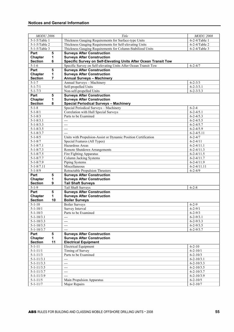
Notices and General Information
ABS RULES FOR BUILDING AND CLASSING MOBILE OFFSHORE DRILLING UNITS . 2008 55
MODU 2006 Title MODU 2008 5-1-5/Table 1 Thickness Gauging Requirements for Surface-type Units 6-2-4/Table 1 5-1-5/Table 2 Thickness Gauging Requirements for Self-elevating Units 6-2-4/Table 2 5-1-5/Table 3 Thickness Gauging Requirements for Column-Stabilized Units 6-2-4/Table 3 Part 5 Chapter 1 Section 6
Surveys After Construction Surveys After Construction Specific Survey on Self-Elevating Units After Ocean Transit Tow
5-1-6 Specific Survey on Self-elevating Units After Ocean Transit Tow 6-2-4/7 Part 5 Chapter 1 Section 7
Surveys After Construction Surveys After Construction Annual Surveys – Machinery
5-1-7 Annual Surveys – Machinery 6-2-3/3 5-1-7/1 Self-propelled Units 6-2-3/3.1 5-1-7/3 Non-self-propelled Units 6-2-3/3.3 Part 5 Chapter 1 Section 8
Surveys After Construction Surveys After Construction Special Periodical Surveys – Machinery
5-1-8 Special Periodical Surveys – Machinery 6-2-4 5-1-8/1 Correlation with Hull Special Surveys 6-2-4/5.1 5-1-8/3 Parts to be Examined 6-2-4/5.3 5-1-8/3.1 --- 6-2-4/5.5 5-1-8/3.3 --- 6-2-4/5.7 5-1-8/3.5 --- 6-2-4/5.9 5-1-8/3.7 --- 6-2-4/5.11 5-1-8/5 Units with Propulsion-Assist or Dynamic Position Certification 6-2-4/7 5-1-8/7 Special Features (All Types) 6-2-4/11 5-1-8/7.1 Hazardous Areas 6-2-4/11.1 5-1-8/7.3 Remote Shutdown Arrangements 6-2-4/11.3 5-1-8/7.5 Fire Fighting Apparatus 6-2-4/11.5 5-1-8/7.7 Column Jacking Systems 6-2-4/11.7 5-1-8/7.9 Piping Systems 6-2-4/11.9 5-1-8/7.11 Miscellaneous 6-2-4/11.11 5-1-8/9 Retractable Propulsion Thrusters 6-2-4/9 Part 5 Chapter 1 Section 9
Surveys After Construction Surveys After Construction Tail Shaft Surveys
5-1-9 Tail Shaft Surveys 6-2-8 Part 5 Chapter 1 Section 10
Surveys After Construction Surveys After Construction Boiler Surveys
5-1-10 Boiler Surveys 6-2-9 5-1-10/1 Survey Interval 6-2-9/1 5-1-10/3 Parts to be Examined 6-2-9/3 5-1-10/3.1 --- 6-2-9/3.1 5-1-10/3.3 --- 6-2-9/3.3 5-1-10/3.5 --- 6-2-9/3.5 5-1-10/3.7 --- 6-2-9/3.7 Part 5 Chapter 1 Section 11
Surveys After Construction Surveys After Construction Electrical Equipment
5-1-11 Electrical Equipment 6-2-10 5-1-11/1 Timing of Survey 6-2-10/1 5-1-11/3 Parts to be Examined 6-2-10/3 5-1-11/3.1 --- 6-2-10/3.1 5-1-11/3.3 --- 6-2-10/3.3 5-1-11/3.5 --- 6-2-10/3.5 5-1-11/3.7 --- 6-2-10/3.7 5-1-11/3.9 --- 6-2-10/3.9 5-1-11/5 Main Propulsion Apparatus 6-2-10/5 5-1-11/7 Major Repairs 6-2-10/7
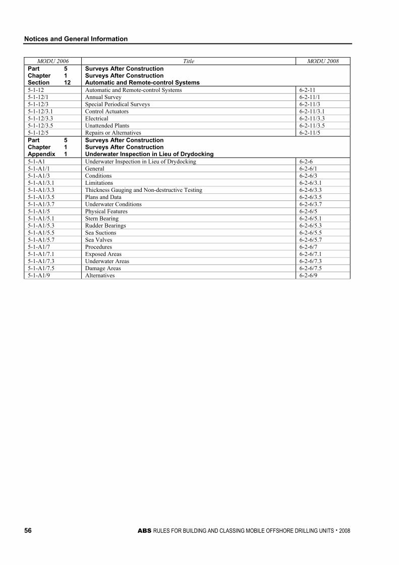
Notices and General Information
56 ABS RULES FOR BUILDING AND CLASSING MOBILE OFFSHORE DRILLING UNITS . 2008
MODU 2006 Title MODU 2008 Part 5 Chapter 1 Section 12
Surveys After Construction Surveys After Construction Automatic and Remote-control Systems
5-1-12 Automatic and Remote-control Systems 6-2-11 5-1-12/1 Annual Survey 6-2-11/1 5-1-12/3 Special Periodical Surveys 6-2-11/3 5-1-12/3.1 Control Actuators 6-2-11/3.1 5-1-12/3.3 Electrical 6-2-11/3.3 5-1-12/3.5 Unattended Plants 6-2-11/3.5 5-1-12/5 Repairs or Alternatives 6-2-11/5 Part 5 Chapter 1 Appendix 1
Surveys After Construction Surveys After Construction Underwater Inspection in Lieu of Drydocking
5-1-A1 Underwater Inspection in Lieu of Drydocking 6-2-6 5-1-A1/1 General 6-2-6/1 5-1-A1/3 Conditions 6-2-6/3 5-1-A1/3.1 Limitations 6-2-6/3.1 5-1-A1/3.3 Thickness Gauging and Non-destructive Testing 6-2-6/3.3 5-1-A1/3.5 Plans and Data 6-2-6/3.5 5-1-A1/3.7 Underwater Conditions 6-2-6/3.7 5-1-A1/5 Physical Features 6-2-6/5 5-1-A1/5.1 Stern Bearing 6-2-6/5.1 5-1-A1/5.3 Rudder Bearings 6-2-6/5.3 5-1-A1/5.5 Sea Suctions 6-2-6/5.5 5-1-A1/5.7 Sea Valves 6-2-6/5.7 5-1-A1/7 Procedures 6-2-6/7 5-1-A1/7.1 Exposed Areas 6-2-6/7.1 5-1-A1/7.3 Underwater Areas 6-2-6/7.3 5-1-A1/7.5 Damage Areas 6-2-6/7.5 5-1-A1/9 Alternatives 6-2-6/9


![ch13 part2 [Uyumluluk Modu] - baskent.edu.tr](https://static.fdocuments.us/doc/165x107/6267b9ab942f6b1ebe44e0ba/ch13-part2-uyumluluk-modu-.jpg)
![Akel Company Profile [Uyumluluk Modu]](https://static.fdocuments.us/doc/165x107/62028d0d409728628d77d1bf/akel-company-profile-uyumluluk-modu.jpg)