ModSim Challenges in Co-Design of Embedded Cooling...
25
ModSim Challenges in Co-Design of Embedded Cooling Solutions A. Bar-Cohen, DARPA-MTO K. Matin, SPC ModSim 2015 Workshop Seattle, Wa 8/12/15 – 8/14/15 Distribution Statement A, Approved For Public Release, Distribution Unlimited
Transcript of ModSim Challenges in Co-Design of Embedded Cooling...
ModSim Challenges in Co-Design of Embedded Cooling Solutions
A. Bar-Cohen, DARPA-MTO K. Matin, SPC
ModSim 2015 Workshop Seattle, Wa
8/12/15 – 8/14/15
Distribution Statement A, Approved For Public Release, Distribution Unlimited
2
Presentation Roadmap
Why Embedded Cooling?
DARPA’s ICECool Program Modeling and Co-Design Challenges
in Embedded Cooling
Distribution Statement A, Approved For Public Release, Distribution Unlimited
3
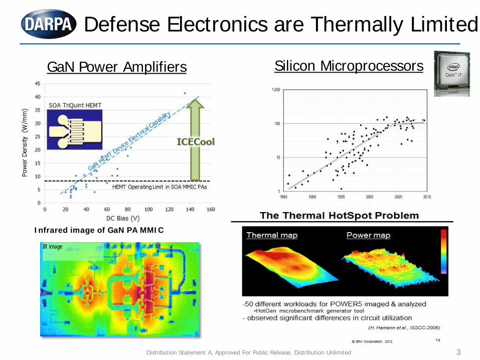
Defense Electronics are Thermally Limited
Intel Itanium Infrared image of GaN PA MMIC
IR image
GaN Power Amplifiers Silicon Microprocessors
Distribution Statement A, Approved For Public Release, Distribution Unlimited
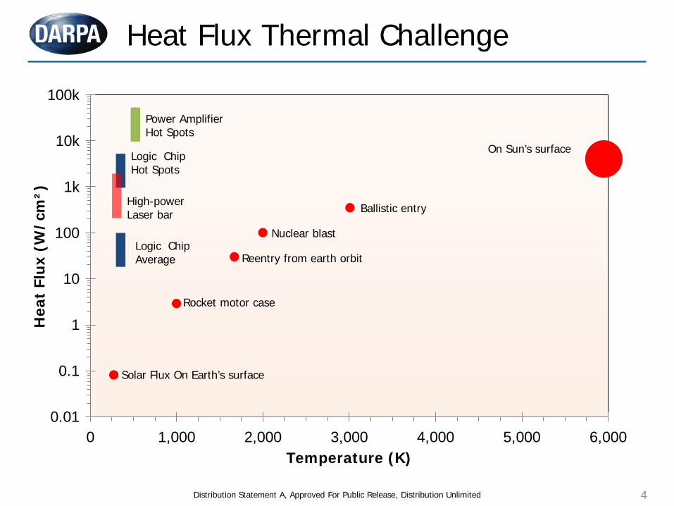
Heat Flux Thermal Challenge
0 1,000 2,000 3,000 4,000 5,000 6,000
Hea
t Fl
ux (
W/c
m²)
Temperature (K)
Logic Chip Average
On Sun’s surface
Solar Flux On Earth’s surface
Rocket motor case
Reentry from earth orbit
Nuclear blast
Ballistic entry
Logic Chip Hot Spots
Power Amplifier Hot Spots
100k
10k
1k
100
10
1
0.1
0.01
High-power Laser bar
Distribution Statement A, Approved For Public Release, Distribution Unlimited 4
Distribution Statement A, Approved For Public Release, Distribution Unlimited 5
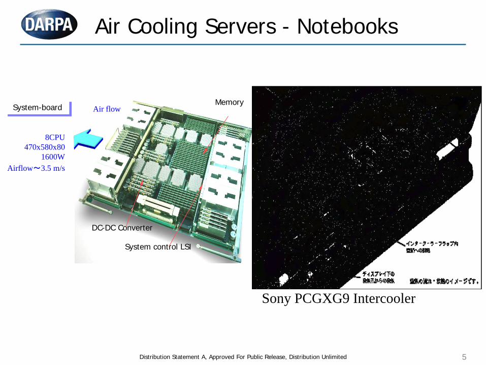
System control LSI
DC-DC Converter
Memory System-board
8CPU 470x580x80
1600W Airflow~3.5 m/s
Air flow
Sony PCGXG9 Intercooler
Air Cooling Servers - Notebooks
Distribution Statement A, Approved For Public Release, Distribution Unlimited 6
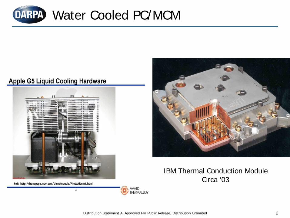
IBM Thermal Conduction Module Circa ‘03
Water Cooled PC/MCM
7
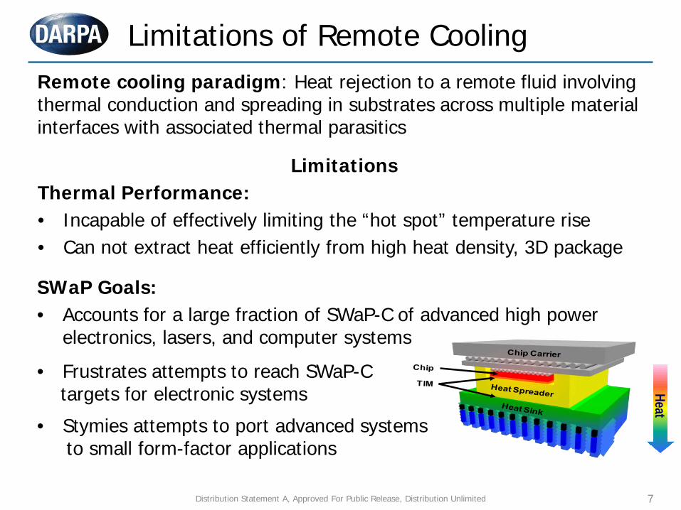
Remote cooling paradigm: Heat rejection to a remote fluid involving thermal conduction and spreading in substrates across multiple material interfaces with associated thermal parasitics
Limitations of Remote Cooling Heat
SWaP Goals: • Accounts for a large fraction of SWaP-C of advanced high power
electronics, lasers, and computer systems
• Frustrates attempts to reach SWaP-C targets for electronic systems
• Stymies attempts to port advanced systems to small form-factor applications
Limitations Thermal Performance: • Incapable of effectively limiting the “hot spot” temperature rise • Can not extract heat efficiently from high heat density, 3D package
Distribution Statement A, Approved For Public Release, Distribution Unlimited
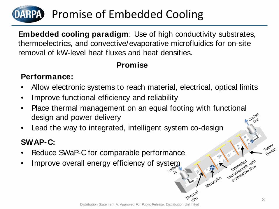
Promise of Embedded Cooling
8
Promise Performance: • Allow electronic systems to reach material, electrical, optical limits • Improve functional efficiency and reliability • Place thermal management on an equal footing with functional
design and power delivery • Lead the way to integrated, intelligent system co-design
SWAP-C: • Reduce SWaP-C for comparable performance • Improve overall energy efficiency of system
Distribution Statement A, Approved For Public Release, Distribution Unlimited
Embedded cooling paradigm: Use of high conductivity substrates, thermoelectrics, and convective/evaporative microfluidics for on-site removal of kW-level heat fluxes and heat densities.
9
Virtual Prototyping of Embedded Cooling
Virtual Prototyping enabled by “multi-physics” co-simulation DoD Investment in Virtual Prototyping - “Innovation Engine” HPCMP - High Performance Computer Modernization
Program CREATE – Computational Research and Engineering
Acquisition Tools and Environments Extend to Thermal-Mechanical-Electrical interactions Apply sequentially to: Virtual Proof of Concept Detailed design Functional and performance optimization Physics of Failure and Reliability of components/system Cost of usage and maintenance Health Maintenance and End-of-Life
Distribution Statement A, Approved For Public Release, Distribution Unlimited
10
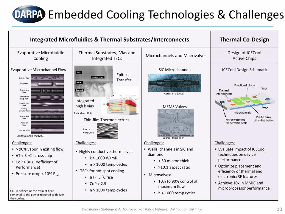
Embedded Cooling Technologies & Challenges
Integrated Microfluidics & Thermal Substrates/Interconnects Thermal Co-Design
Evaporative Microfluidic Cooling
Thermal Substrates, Vias and Integrated TECs Microchannels and Microvalves Design of ICECool
Active Chips
Evaporative Microchannel Flow
Serizawa and Feng (2001)
Thin-film Thermoelectrics
Integrated high k vias
Challenges:
• Highly conductive thermal vias • k > 1000 W/mK • n > 1000 temp cycles
• TECs for hot spot cooling • ΔT < 5 0C rise • CoP > 2.5 • n > 1000 temp cycles
Challenges: • > 90% vapor in exiting flow • ΔT < 5 0C across chip • CoP > 30 (Coefficient of
Performance) • Pressure drop < 10% Psat
SiC Microchannels
MEMS Valves
Challenges: • Walls, channels in SiC and
diamond • < 50 micron thick • >10:1 aspect ratio
• Microvalves: • 10% to 90% control of
maximum flow • n > 1000 temp cycles
ICECool Design Schematic
Challenges: • Evaluate impact of ICECool
techniques on device performance
• Optimize placement and efficiency of thermal and electronic/RF features
• Achieve 10x in MMIC and microprocessor performance
CoP is defined as the ratio of heat removed to the power required to deliver the cooling.
Balandin (1999)
Source: Nextreme
Source: Texas Tech
Carter et al(2009)
Distribution Statement A, Approved For Public Release, Distribution Unlimited
Epitaxial Transfer

11
I. Passive “Thermally-Informed” Design
• Uniformly distribute functional tasks
• Avoid creating hot spots II. Active Thermal Co-Design
• Functional blocks/paths and thermal elements placed in most favorable locations
• Functional blocks remapped to accommodate temperature effects
III. Fully-Integrated Thermal Co-Design
• Create passive/active thermal interconnect network
• optimize layout for energy consumption and functional performance
Hierarchy of Thermal-Electrical Co-Design
Source: B. Shi, A. Srivastava and A. Bar-Cohen, “Hybrid 3D-IC Cooling System Using Micro-Fluidic Cooling and Thermal TSVs “, To Appear ISVLSI, Aug 2012
Distribution Statement A, Approved For Public Release, Distribution Unlimited
12
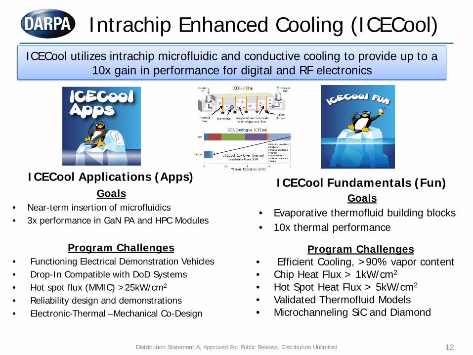
Intrachip Enhanced Cooling (ICECool)
Intel Itanium
ICECool utilizes intrachip microfluidic and conductive cooling to provide up to a 10x gain in performance for digital and RF electronics
ICECool Applications (Apps) Goals
• Near-term insertion of microfluidics • 3x performance in GaN PA and HPC Modules
Program Challenges • Functioning Electrical Demonstration Vehicles
• Drop-In Compatible with DoD Systems • Hot spot flux (MMIC) >25kW/cm2
• Reliability design and demonstrations • Electronic-Thermal –Mechanical Co-Design
ICECool Fundamentals (Fun) Goals
• Evaporative thermofluid building blocks • 10x thermal performance
Program Challenges • Efficient Cooling, >90% vapor content • Chip Heat Flux > 1kW/cm2
• Hot Spot Heat Flux > 5kW/cm2
• Validated Thermofluid Models • Microchanneling SiC and Diamond
Distribution Statement A, Approved For Public Release, Distribution Unlimited
13
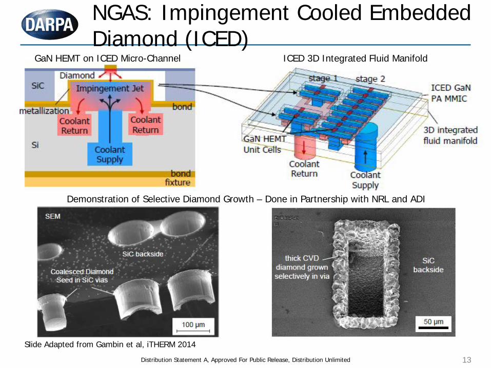
NGAS: Impingement Cooled Embedded Diamond (ICED)
Distribution Statement A, Approved For Public Release, Distribution Unlimited
Demonstration of Selective Diamond Growth – Done in Partnership with NRL and ADI
GaN HEMT on ICED Micro-Channel ICED 3D Integrated Fluid Manifold
Slide Adapted from Gambin et al, iTHERM 2014
14
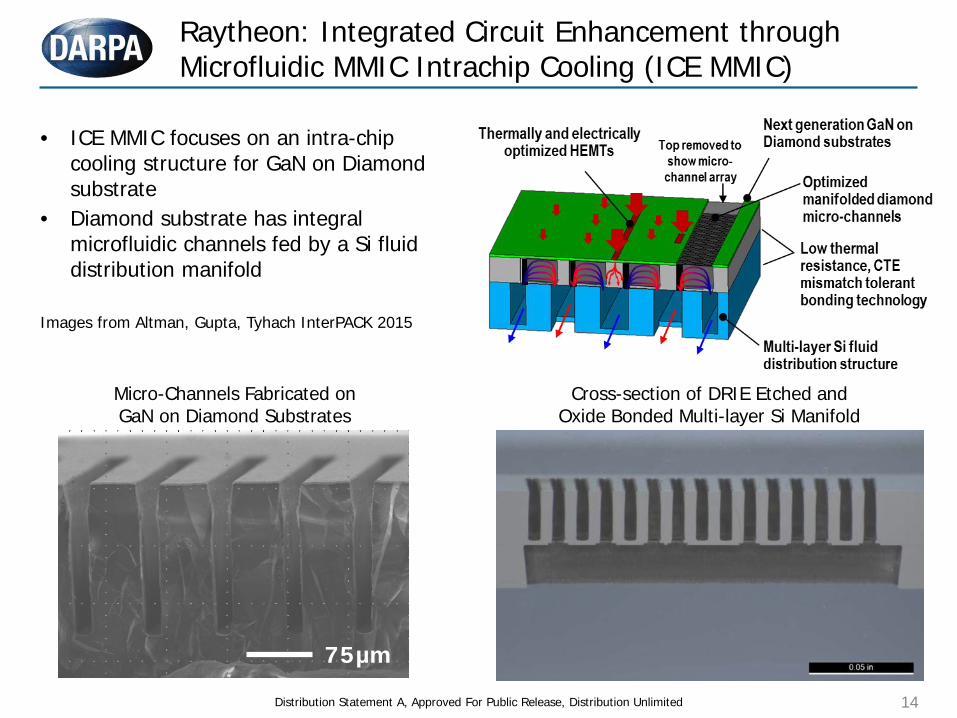
Raytheon: Integrated Circuit Enhancement through Microfluidic MMIC Intrachip Cooling (ICE MMIC)
Distribution Statement A, Approved For Public Release, Distribution Unlimited
• ICE MMIC focuses on an intra-chip cooling structure for GaN on Diamond substrate
• Diamond substrate has integral microfluidic channels fed by a Si fluid distribution manifold
75µm
Micro-Channels Fabricated on GaN on Diamond Substrates
Cross-section of DRIE Etched and Oxide Bonded Multi-layer Si Manifold
Images from Altman, Gupta, Tyhach InterPACK 2015
15
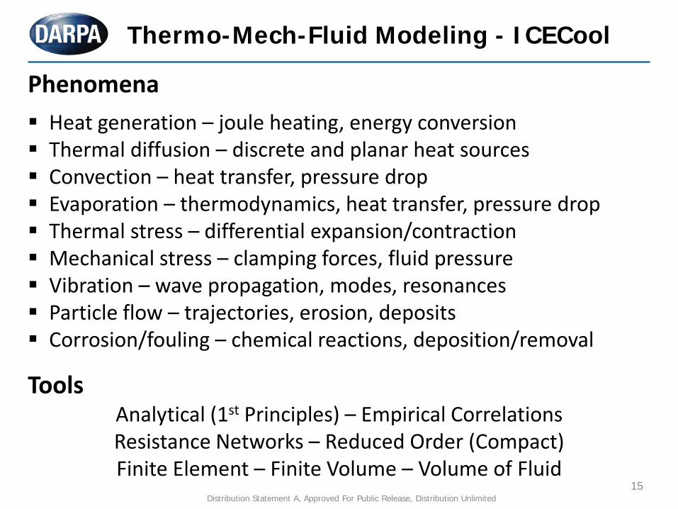
Thermo-Mech-Fluid Modeling - ICECool
Phenomena
Heat generation – joule heating, energy conversion Thermal diffusion – discrete and planar heat sources Convection – heat transfer, pressure drop Evaporation – thermodynamics, heat transfer, pressure drop Thermal stress – differential expansion/contraction Mechanical stress – clamping forces, fluid pressure Vibration – wave propagation, modes, resonances Particle flow – trajectories, erosion, deposits Corrosion/fouling – chemical reactions, deposition/removal
Tools Analytical (1st Principles) – Empirical Correlations Resistance Networks – Reduced Order (Compact) Finite Element – Finite Volume – Volume of Fluid
Distribution Statement A, Approved For Public Release, Distribution Unlimited
16
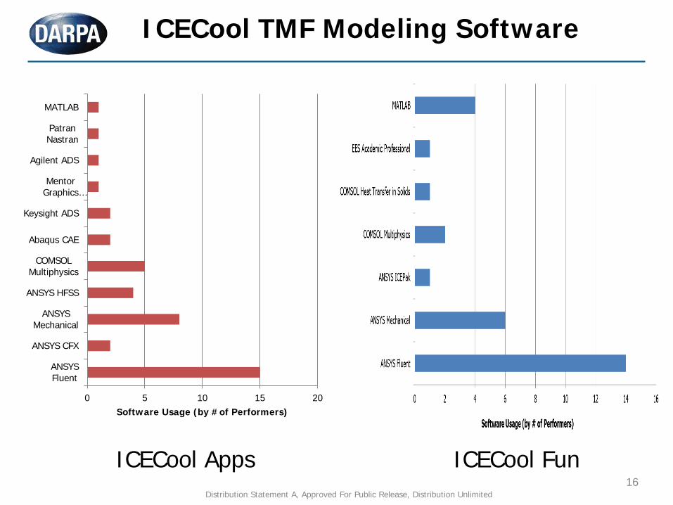
ICECool Apps ICECool Fun
0 5 10 15 20
ANSYSFluent
ANSYS CFX
ANSYSMechanical
ANSYS HFSS
COMSOLMultiphysics
Abaqus CAE
Keysight ADS
MentorGraphics…
Agilent ADS
PatranNastran
MATLAB
Software Usage (by #of Performers)
ICECool TMF Modeling Software
Distribution Statement A, Approved For Public Release, Distribution Unlimited
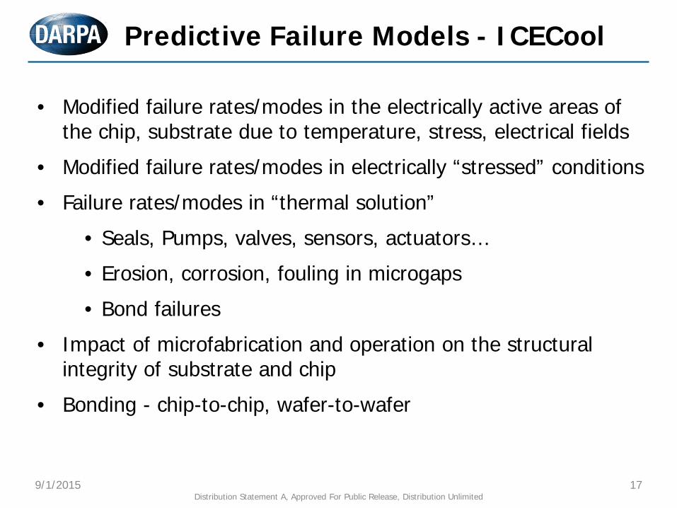
• Modified failure rates/modes in the electrically active areas of the chip, substrate due to temperature, stress, electrical fields
• Modified failure rates/modes in electrically “stressed” conditions
• Failure rates/modes in “thermal solution”
• Seals, Pumps, valves, sensors, actuators…
• Erosion, corrosion, fouling in microgaps
• Bond failures
• Impact of microfabrication and operation on the structural integrity of substrate and chip
• Bonding - chip-to-chip, wafer-to-wafer
Predictive Failure Models - ICECool
9/1/2015 17 Distribution Statement A, Approved For Public Release, Distribution Unlimited
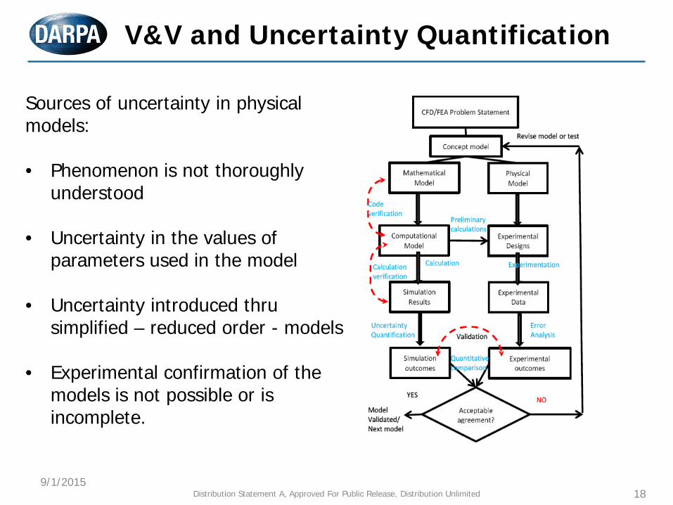
V&V and Uncertainty Quantification
9/1/2015 18
Sources of uncertainty in physical models:
• Phenomenon is not thoroughly
understood
• Uncertainty in the values of parameters used in the model
• Uncertainty introduced thru simplified – reduced order - models
• Experimental confirmation of the models is not possible or is incomplete.
Distribution Statement A, Approved For Public Release, Distribution Unlimited
19
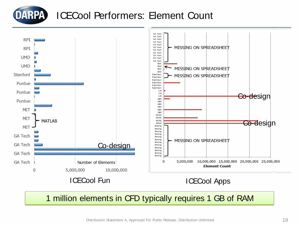
ICECool Performers: Element Count
Number of Elements
1 million elements in CFD typically requires 1 GB of RAM
Co-design
Co-design
Co-design
ICECool Fun ICECool Apps
Distribution Statement A, Approved For Public Release, Distribution Unlimited
0 10 20 30 40 50
GA Tech
GA Tech
GA Tech
GA Tech
MIT
MIT
MIT
Purdue
Purdue
Purdue
Stanford
UMD
UMD
RPI
RPI
cores
20
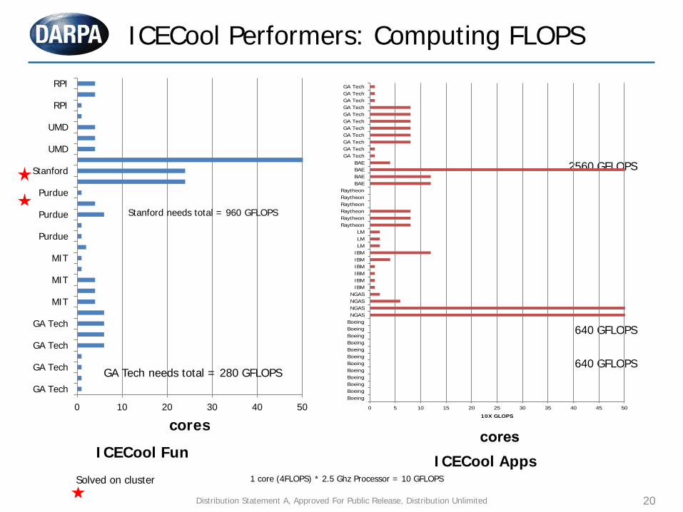
ICECool Performers: Computing FLOPS
Solved on cluster
Stanford needs total = 960 GFLOPS
1 core (4FLOPS) * 2.5 Ghz Processor = 10 GFLOPS
GA Tech needs total = 280 GFLOPS
2560 GFLOPS
640 GFLOPS
640 GFLOPS
0 5 10 15 20 25 30 35 40 45 50
BoeingBoeingBoeingBoeingBoeingBoeingBoeingBoeingBoeingBoeingBoeingBoeingNGASNGASNGASNGAS
IBMIBMIBMIBMIBMIBMLMLMLM
RaytheonRaytheonRaytheonRaytheonRaytheonRaytheon
BAEBAEBAEBAE
GA TechGA TechGA TechGA TechGA TechGA TechGA TechGA TechGA TechGA TechGA Tech
10X GLOPS
ICECool Fun ICECool Apps
Distribution Statement A, Approved For Public Release, Distribution Unlimited
21
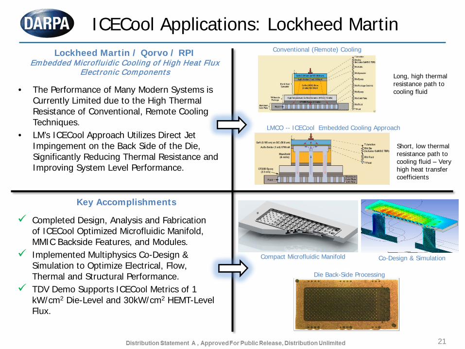
ICECool Applications: Lockheed Martin
• The Performance of Many Modern Systems is Currently Limited due to the High Thermal Resistance of Conventional, Remote Cooling Techniques.
• LM’s ICECool Approach Utilizes Direct Jet Impingement on the Back Side of the Die, Significantly Reducing Thermal Resistance and Improving System Level Performance.
Lockheed Martin / Qorvo / RPI Embedded Microfluidic Cooling of High Heat Flux
Electronic Components
Completed Design, Analysis and Fabrication of ICECool Optimized Microfluidic Manifold, MMIC Backside Features, and Modules.
Implemented Multiphysics Co-Design & Simulation to Optimize Electrical, Flow, Thermal and Structural Performance.
TDV Demo Supports ICECool Metrics of 1 kW/cm2 Die-Level and 30kW/cm2 HEMT-Level Flux.
Key Accomplishments
Conventional (Remote) Cooling
LMCO -- ICECool Embedded Cooling Approach
Long, high thermal resistance path to cooling fluid
Short, low thermal resistance path to cooling fluid – Very high heat transfer coefficients
Compact Microfluidic Manifold
Die Back-Side Processing
Co-Design & Simulation
22
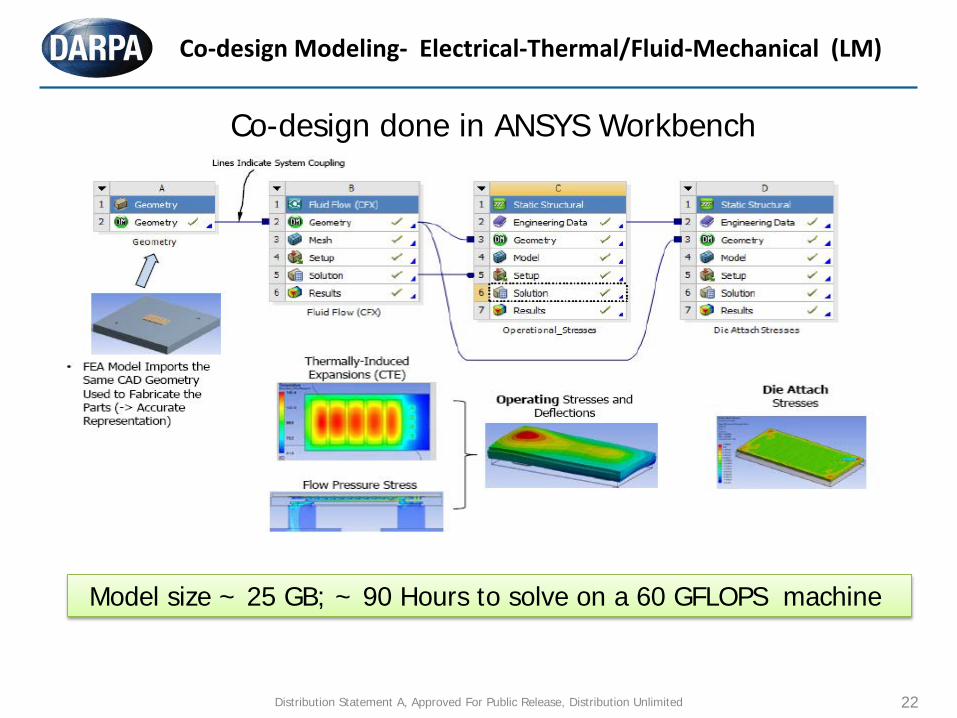
Co-design Modeling- Electrical-Thermal/Fluid-Mechanical (LM)
Model size ~ 25 GB; ~ 90 Hours to solve on a 60 GFLOPS machine
Co-design done in ANSYS Workbench
Distribution Statement A, Approved For Public Release, Distribution Unlimited

23
• Lagrangian Particle Tracking is a Coupled-Field Simulation, Computing trajectory of particles
• orces Acting on the Particles are Inertia, Viscous Drag, Buoyancy, “Virtual Mass” and Pressure .
Case Study: Erosion Modeling (LM) – Particle Tracking
Particles of Varying Size are Injected at the Inlet of the Domain.
Particle Trajectories are Influenced By Geometry and Fluid Flow. They are calculated by solving PDE’s.
Particles eventually exit the domain.
Model size ~ 5 GB; ~ 15 Hours to solve on a 60 GFLOPS machine
Distribution Statement A, Approved For Public Release, Distribution Unlimited
24
Closure
Why Embedded Cooling?
DARPA’s ICECool Program Modeling and Co-Design Challenges
in Embedded Cooling
Distribution Statement A, Approved For Public Release, Distribution Unlimited

www.darpa.mil
25 Distribution Statement A, Approved For Public Release, Distribution Unlimited