Modifications of SHS processes
12
Pure & Appl. Chem., Vol. 64, No. 7, pp. 977-988, 1992. Printed in Great Britain. @ 1992 IUPAC Modifications of SHS processes V. 1.Yukhvid Institute of Structural Macrokinetics, USSR Academy of Sciences 142432, Chernogolovka,Moscow Region, USSR Abstract- Proceeding from the kind of the chemical bond, the majority of the processing versions of the self - propagating high-temperature synthesis (SHS) of the refractory inorganic compounds can be divided into two groups: ,element and oxide. By performing the chemical transformation in the combustion mode and employing the high exothermic nature of the initial systems, processing techniques and special equipment, it is possible to tackle the various practical problems and obtain the SHS spectrum of the products, namely: powders and compacts (Tic ,Sic, Cr C 3 2’ TaC, B4C, TiB2, CrB2, MoSi2, TiSi2, V3Si, TiN, BN,AlN, Si3N4, YBa2Cu307-x and others), high-dense items manufactured from the above-listed materials (rollers,pipes, milling cutters, cutters, electrodes, bushings, rings etc.) and the items with the preset porosity (filters), as well as to weld the refractory materials (graphite with graphite, steel with carbide alloys, molybdenum with molybdenum and so on) and to obtain the protective coatings of various thickness. INTRODUCTION In 1967, A.G.Merzhanov , 1.P.Borovinskaya and V.M.Shkiro have discovered the phenomenon of self-propagating high-temperature synthesis of refractory inorganic materials: carbides, borides, silicides, hydrides, oxides, chalcogenides, carbide alloys, composite materials and so on (ref.l).Within more than 20 years, the school of professor A.G.Merzhanov fundamentally investigated the SHS process developed the various SHS processing techniques and special equipment obtained the wide range of materials, items and coatings , as well as studied the raw materials and commercial efficiency for some practical problems (ref. 1-35]. The chronology of creating (editions) of the SHS versions in the USSR is as follows: 1967 - the long-propagating high-temperature synthesis of the elements in vacuum, inert gas or reacting gas (ref .l); 1975 - the long-propagating high-temperature synthesis with reducing medium, SHS metallurgy, centrifugal SHS casting, SHS surfacing (ref.221; 1976 - SHS welding of refzactory materials (ref.23); 1978 - SHS process with sintering under high gas pressure (P>lO Pa) (ref.5); 1980 - SHS process with action of shock waves (ref.34); 1981 - SHS process with extrusion (ref.35); 1986 - SHS process with the use of gas-transport medium (ref.9). At the present time, many cities of the USSR have the scientific and engineering centers of the SHS processes (Moscow, Erevan, Tbilisi, Alma-Ata,Minsk, Samara, Dnepropetrovsk, Tomsk etc.). At the beginning of 80th, the scientists from the USA (ref.36,37,43 to 45,51 to 54) Japan (39 to 42,46,48 to 50,56 to 581,and other countries also started to investigate the SHS processes.. SPECIFIC FEATURES OF SHS PROCESSING TECHNIQUES AND COMBUSTION PROCESS In the processing steps, three stages can be distinguished: preliminary operations, SHS process and the working process of the self -propagating high-temperature synthesis (ref.l5).To obtain the compacts and items, the additional operation is performed: after combustion is over, the mixtures heated up to the high-temperature are subject to pressing, extrusion, explosion reduction, rolling etc. 1. 977
Transcript of Modifications of SHS processes

Pure & Appl. Chem., Vol. 64, No. 7, pp. 977-988, 1992. Printed in Great Britain. @ 1992 IUPAC
Modifications of SHS processes
V. 1.Yukhvid
Institute of Structural Macrokinetics, USSR Academy of Sciences 142432, Chernogolovka,Moscow Region, USSR
Abstract- Proceeding from the kind of the chemical bond, the majority of t h e processing versions of the self - propagating high-temperature synthesis (SHS) of the refractory inorganic compounds can be divided into two groups: ,element and oxide. By performing the chemical transformation in the combustion mode and employing the high exothermic nature of the initial systems, processing techniques and special equipment, i t i s possible t o tackle the various practical problems and obtain the SHS spectrum of the products, namely: powders and compacts (Tic ,S ic , Cr C
3 2’ TaC, B4C, TiB2, CrB2, MoSi2, TiSi2, V3Si, TiN, BN,AlN, Si3N4, YBa2Cu307-x
and others), high-dense items manufactured from the above-listed materials (rollers,pipes, milling cut ters , cut ters , electrodes, bushings, rings etc.) and the items with the preset porosity ( f i l ters) , as well as t o weld the refractory materials (graphite with graphite, steel with carbide alloys, molybdenum with molybdenum and so on) and t o obtain the protective coatings of various thickness.
INTRODUCTION
In 1967, A.G.Merzhanov , 1.P.Borovinskaya and V.M.Shkiro have discovered the phenomenon of self-propagating high-temperature synthesis of refractory inorganic materials: carbides, borides, silicides, hydrides, oxides, chalcogenides, carbide alloys, composite materials and so on (ref.l).Within more than 20 years, the school of professor A.G.Merzhanov fundamentally investigated the SHS process developed the various SHS processing techniques and special equipment obtained the wide range of materials, items and coatings , as well as studied the r a w materials and commercial efficiency f o r some practical problems (ref . 1-35].
The chronology of creating (editions) of the SHS versions in the USSR is as follows: 1967 - the long-propagating high-temperature synthesis of the elements in vacuum, iner t gas or reacting gas (ref . l ) ; 1975 - the long-propagating high-temperature synthesis with reducing medium, SHS metallurgy, centrifugal SHS casting, SHS surfacing (ref.221; 1976 - SHS welding of refzactory materials (ref.23); 1978 - SHS process with sintering under high gas pressure (P>lO Pa) (ref.5); 1980 - SHS process with action of shock waves (ref.34); 1981 - SHS process with extrusion (ref.35); 1986 - SHS process with the use of gas-transport medium (ref.9). A t the present time, many cities of the USSR have the scientific and engineering centers of the SHS processes (Moscow, Erevan, Tbilisi, Alma-Ata,Minsk, Samara, Dnepropetrovsk, Tomsk etc.). A t the beginning of 80th, the scientists f rom the USA (ref.36,37,43 t o 45,51 t o 54) Japan (39 t o 42,46,48 t o 50,56 t o 581,and other countries also s ta r ted t o investigate the SHS processes..
SPECIFIC FEATURES OF SHS PROCESSING TECHNIQUES A N D COMBUSTION PROCESS
In the processing steps, three stages can be distinguished: preliminary operations, SHS process and the working process of the self -propagating high-temperature synthesis (ref.l5).To obtain the compacts and items, the additional operation i s performed: a f t e r combustion is over, the mixtures heated up t o the high-temperature a r e subject t o pressing, extrusion, explosion reduction, rolling etc. 1.
977
978 V. I. YUKHVID
The most specific stage among the above-listed i s the SHS process proper. I t i s effected in the following way.The initial mixture in the form of pellets or in bulk prepared f o r synthesis is placed in the reaction envelope (reactor) and becomes ignited in any point of the surface 1ayer.After ignition (within the small time period), the combustion f ront is formed which spontaneously moves over the mixture. The linear average rate of combustion (Uo) i s in a n interval of 0.1 to 10 cm/s depending on t h e chemical composition of the
mixture, reagent dispersity and other parameters. In the f ront of combustion, the thickness of which amounts 0.1 t o 1 mm, the initial mixture is chemically transformed into the synthesis products. The chemical transformation i s accompanied by evolution of great amount of gases which heat the synthesis products up t o 1000 t o 4000'K (ref.15).
When developing the process techniques, the specific fea tures of interaction of the condensed and gaseous phases of the self -propagating high-temperature synthesis process shall be taken into consideration. In the combustion wave, the gaseous substances can be evaluated(H ,N and so on ),be absorbed (filtration combustion - synthesis of nitrides and
hydrides) or be practically absent (free-of-gas combustion (ref .6 to 8) .
Volume (V ) of the gaseous products reduced t o the nominal conditions may amount f rom 10
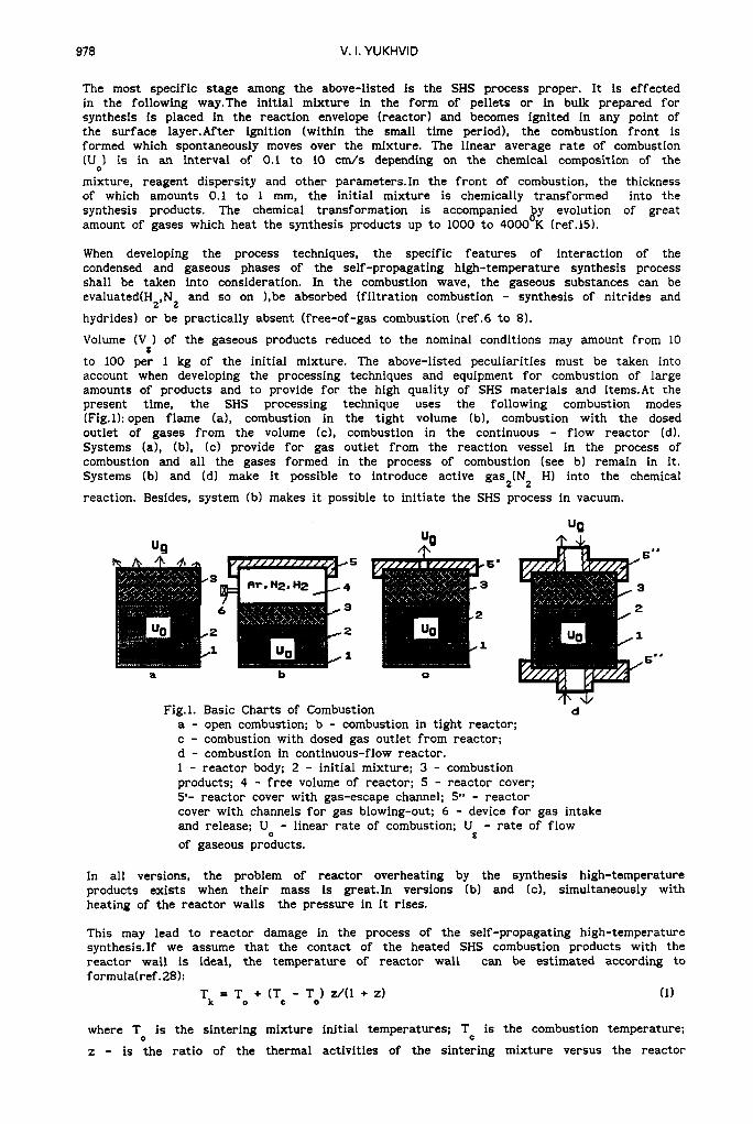
t o 100 per 1 kg of the initial mixture. The above-listed peculiarities must be taken into account when developing the processing techniques and equipment f o r combustion of large amounts of products and t o provide f o r the high quality of SHS materials and items.At the present time, t h e SHS processing technique uses the following combustion modes (Fig.l):open flame (a), combustion in the tight volume (b) , combustion with the dosed outlet of gases from the volume (c), combustion in the continuous - flow reactor (d). Systems (a), (b), (c) provide f o r gas outlet f rom the reaction vessel in the process of combustion and all the gases formed in the process of combustion (see b) remain in it. Systems (b) and (d) make i t possible t o introduce active gas2(N2 HI into the chemical
reaction. Besides, system (b) makes i t possible t o initiate the SHS process in vacuum.
2 2
0
"Q
Fig.1. Basic Charts of Combustion d a - open combustion; b - combustion in tight reactor; c - combustion with dosed gas outlet f rom reactor; d - combustion in continuous-flow reactor. 1 - reactor body; 2 - initial mixture; 3 - combustion products; 4 - f r e e volume of reactor; 5 - reactor cover; 5'- reactor cover with gas-escape channel; 5" - reactor cover with channels f o r gas blowing-out; 6 - device f o r gas intake and release; Uo - linear rate of combustion; U - rate of flow of gaseous products.
g
In a l l versions, the problem of reactor overheating by the synthesis high-temperature products exis ts when their mass i s great.In versions (b) and (c), simultaneously with heating of the reactor walls the pressure in i t rises.
This may lead t o reactor damage in the process of the self-propagating high-temperature synthesis.If we assume t h a t the contact of the heated SHS combustion products with the reactor wall is ideal, the temperature of reactor wall can be estimated according t o formula(ref .28):
Tk = To + (T, - To) z/(l + z) (1)
where T i s the sintering mixture initial temperatures; Tc is the combustion temperature;
z - is the ra t io of the thermal activities of the sintering mixture versus the reactor 0

Modifications of SHS processes 979
wall material. For the typical values of the parameters - To=3000K, Tc=3000K, wl, we have
T value which i s approximately equals t o 165O0K.The temperature in the reactor wall can
be considerably reduced by placing the graphite casing between the wall and sintering mixture or by cooling the reactor with running water . In the las t case, according t o the thermocouple measurements, temperature Tk can be reduced down t o about 100°K. The dynamics
of the reactor pressure in the process of combustion depend upon combustion shown in Fig. 2.
k
P
a
P m
Fig.2. Specific Dynamics of Pressure in SHS Reactor a - under conditions of tight combustion; b - under conditions of dosed gas outlet; P , P , Pi- current, initial and maximum pressure
t - current time;
1 0 in reactor;
tc - combustion time of mixture in reactor.
b
I t is evident tha t the maximum pressure in the reactor (P*) should not exceed some critical pressure value (P+) determined by the reactor strength:
P' s P+ (2)
Assuming tha t the destruction of the reactor i s connected with the yield point (P for calculation PI proceeding from force balance, we have: Y
P+ 5 kT A/d P
(3)
where d i s the internal diameter; A is the reactor wall thickness. A s i t follows from
formula (31, in order t o increase the maximum permissible pressure in the reactor, i t is necessary t o increase the thickness of its walls and t o reduce the diameter. I t should be noted tha t value Q
P
in expression (3) quickly decreases when the temperature rises. T
The maximum pressure in the tight reactor (P*) in the adiabatic approximation can be estimated by the formula:
P' = Pl(T) + P (M V 1 2 o g
where P i s the par t of the pressure which i s built up at the expense
the reactor; Pz is the par t of the pressure which i s created due t o gas
combustion products; T is temperature; M i s the sintering mixture mass
i s the sintering mixture specific gas-evolution value.
If we assume tha t the equilibrium temperature in the reactor (T=T 1 other, i t follows ( for calculations P1 and Pz) that:
1
D
P1 = Po (Tg/To)
Pz = Pa (V M N p c ) (Tg/To) g o
(4)
of gas heating in
evolution from the
in the reactor; V g
i s equal t o each
( 5 )
(6)
where P i s the initial pressure in the reactor; P is the atmospheric pressure; V is the
reactor volume; E is the fraction of the vacant,volume of the reactor. 0 P

980 V. I. YUKHVID
Proceeding from formulas (4) t o (61, i t follows tha t the maximum pressure in the reactor i s simply regulated by fully loading the reactor (Mo Vp, E ) and by i t s initial pressure
(Po). For the typical values of parameters Po=10 Pa, Pa=105 Pa, Tc=30000K, To=3000K,
Mo=10 kg, V m /kg , V = 2 ~ 1 0 - ~ m3, c=0.5 we obtain the following estimation value:P1 =
lo7 Pa, P’ = 2-107 Pa.For the multipurpose reactors developed in the
Institute of Structural Macrokinetics of the USSR Academy of Sciences, value P+
amounts t o (2 t o 3) lo7 Pa (taking into account the safety margin) and therefore estimation value P’ sat isf ies equation (4).It should be noted t h a t f o r the filtration synthesis of nitrides and hydrides, the addent in formula 4 has t h e negative sign since in this case the gas is absorbed but not evaluated.
For the SHS reactor provided with the dosed outlet (Fig.lc),the maximum pressure is calculated proceeding from the balance of the gas feed from the combustion f ront and reactor gas-escape pipe (ref.28).
Assuming t h a t the f i l t ra t ion of gases from the synthesis products does not limit the gas vent (discharge) process and the pressure drop in the gas-escape channel can be averaged out, we have t h a t (ref.28):
6
3 0 P
P2 = lo7 Pa and
P’ = Pa + (UMVgL/K) (dp/dkI2 (7)
where UM - the mass rate of combustion; L and dk - length and diameter of the gas-escape
channel; K - the proportionality factor .
I t pressure in the given formula (9) tha t the simplest method of adjusting the pressure in the given type of the reactor i s t o change the diameter of the gas-escape channel.
TYPES OF SHS PROCESSING TECHNIQUES
According t o the classification suggested by professor Merzhanov A.G. (ref.151, all known SHS processing techniques can be divided into s ix types: SHS process of manufacturing the blanks and powders, SHS sintering, SHS power compacting, SHS metallurgy, SHS welding and the production process of the SHS coatings. Within the framework of the said SHS versions, i t i s possible t o obtain the wide spectrum of powders and compacts, items and coatings.The quality and process of manufacturing the SHS materials,items and coating application are controlled both with the help of the internal (composition and density of the sintering mixture, relation and dispersivity of reagents etc. ) and external parameters(gas pressure,compacting pressure,centrifugal action,action of the electromagnetic field and ul t ra sound, initial heating by various heat sources and so on).
It should be noted t h a t in the USSR, the intensive works are performed since 1975 pertaining to manufacture of the compact refractory materials and items, thin and thick coatings by the SHS method. Anyhow, the publication of the papers on these tendencies was limited. A t the present time, we wai t f o r the publication of the great amount of papers and reviews dealing with the above-mentioned tendencies of the SHS processes.
SHS PROCESS OF MANUFACTURING BLANKS AND POWDERS
The SHS processing technique f o r manufacturing powders and blanks i s the simplest one. For performing the main technological SHS operation, the various types of the reactors are developed in the USSR which are differ f rom each other by the method of combustion, dimensions and different design versions. Since 1972, the universal SHS apparatus i s used f o r mass production (ref .21) which i s essentially a high-strength steel cylinder provided with two tight locks and quipped with the reactor gas inletloutlet systems, water cooling and ignition, check and remote control of the SHS process. The reactor design makes i t possible t o conduct synthesis in vacuum, in the medium of iner t gases (Ar , He) and reacting gas (N H 1 under the pressure of up t o 2,5*107 Pa, in the mode of the tight
combustion and dosed gas discharge (see Fig.lb,c). Depending on the volume of the working chamber,the output of the universal SHS apparatus amounts t o 10-20 t per one year.
The main role of the inert gas at the SHS process used t o manufacture the refractory inorganic compounds from the solid elements (Ti+C, Si+C, Zr+B, Mo+Si and others) is t o create the protective atmosphere which hinders the penetration of air oxygen and nitrogen into the SHS products.As a rule, the SHS product (a f te r removing from the reactor) is essentially the s inter with low strength and can be mechanically powdered (ref .21).
2’ 2
Modifications of SHS processes 98 1
For synthesizing the oxide mixture with Mg and nonmetals (see schematic 21, the increased pressure of argon both ensures the protection against the product contamination and suppresses the evaluation of volatile component and also helps t o increase the completeness of chemical transformation (ref.71.After grinding the s inter , the final product (Tic, TiB2, B4C and others) i s purified of MgO by dissolving i t in the
hydrochloric acid. After dissolving (without the additional grinding, small-dispersed SHS powders are obtained). This SHS version is referred t o the SHS reduction stage.
To obtain the nitrides, carbonitrides and hydrides (TIN, Ti-C-N, BN, Si N AlN, TiH2,
ZrH and others), the active gas pressure is built up in the reactor volume (N H2). In
this version, the SHS nitrogen pressure i s the important parameter which defines the completeness of absorption of i t s elements ( ref . 12). Besides, the complete chemical transformation is greatly influenced by the f i l t ra t ion characteristics of the mixture and the combustion forms (ref.18).
3 4’
2 2’
Except f o r the universal SHS apparatus and various versions of i t s design, the SHS process of producing powders and materials uses the continuous-flow reactors. The processing schematic (Fig.ld1 and the design of the continuous-flow reactor were developed by the author together with Merzhanov A.G. and Borovinskaya I.P. in 1974-1975. The investigation of the regularity and mechanism of the SHS process with forced f i l t ra t ion in the continuous-flow reactor makes i t possible t o work out the methods which permit t o obtain nitrides (TiN, TaN, NbN) carbides and carbonitrides (Tic, Ti-C-N), as well as the nitride coating on titanium (ref.32). Later on, this procedure was used t o obtain the superconductive ceramics and other materials.
A t the present time, the SHS process makes i t possible t o obtain more than 500 materials: carbides, silicides,nitrides, hydrides, carbonitrides, chalcogenides, oxides (ref.7,12,14,36,37,42) and so on. On an industrial scale, the SHS process of manufacturing the powders was introduced at the end of 70 at the Kirovokan plant of high-temperature heaters where molybdenum disilicide was produced (ref . 15). A s a result, the SHS process revealed its evident advantages in comparison with the furnace process, namely: the increase of the production rate and quality of t h e heaters, decrease of the energy and labour consumption, as well as the increase of the heater service life etc. Besides, the said SHS process f o r producing the silicon carbide powder was introduced in Japan (ref .70). This process i s employed f o r manufacturing the items, refractory bricks and abrasives.
SHS SlNTERlNG
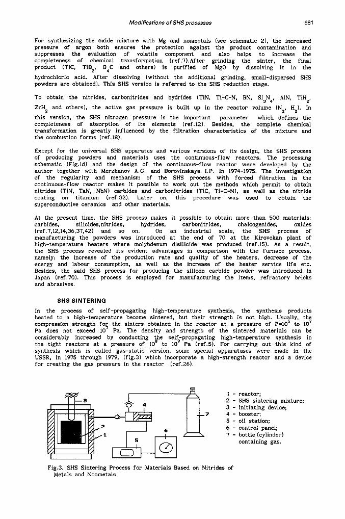
In the process of self -propagating high-temperature synthesis, the synthesis products heated t o a high-temperature become sintered, but their s t rength i s not high. Usu$ly, thq compression s t rength f o r the s inters obtained in the reactor at a pressure of P=lO t o 10 Pa does not exceed lo7 Pa. The density and strength of the sintered materials can be considerably increased by conducting the self-propagating high-temperature synthesis in the tight reactors at a pressure of lo8 t o lo9 Pa (ref.5). For carrying out this kind of synthesis which i s called gas-static version, some special apparatuses were made in the USSR, in 1975 through 1979, (fig.3) which incorporate a high-strength reactor and a device f o r creating the gas pressure in the reactor (ref.26).
I
1 - 2 - 3 - 4 - 5 - 6 - 7 -
reactor; SHS sintering mixture; initiating device; booster; oil station; control panel; bottle (cylinder) containing gas.
Fig.3. SHS Sintering Process f o r Materials Based on Nitrides of Metals and Nonmetals

982 V. 1. YUKHVID
The device includes a booster and an oil station which helps t o tra s f e r the qas found in the cylinder or gas line into the reactor under a pressure of 5-10 t o 1.6.10 Pa and t o built up a pressure in i t of up t o 10 Pa. This gas-static SHS process makes i t possible to obtain the samples of titanium nitride with a porosity of 8 t o 40 per cent, silicon nitride with a porosity of 40 per cent and a bending strength of (1.2 t o 1.5) lo8 Pa, the composite materials based on Sic-Si N having a porosity of about 5 per cent and a bending
strength of (3 t o 6.5) lo8 Pa at T=1800°K. The gas-static SHS process makes i t possible to obtain both the compact materials and the items with the preset shape and dimensions: electrodes and the items f o r electrolysis, crucibles f o r melting refractory and active metals, insulating tubes, rings and bushings f o r the oriented crystallization furnaces, corrosion- and erosion-resistant linings etc. The designs of the apparatuses existing in the USSR make i t possible t o obtain the items with a length of up t o 25-30 cm and a diameter of up 8 cm. Some of the above-mentioned designs are used in the industry.
Great success in the technology of SHS-sintering under the high pressure of gas have been done in Japan in the works Y.Miyamoto, M.Koizumi et.al. beginning in 1986 (ref.39). Unlike the studies carried out by the soviet scientists, these works have not been dealing with the synthesis of the high-compact nitrides and their composites with other materials. The main task of their studies is t o obtain the compact compounds of carbide and titanium boride with metallic bonds or oxides, as well as t o manufacture the high-compact items of the complicated shape (ref.40 t o 42).In these studies, the self-propagating high-temperature synthesi? was carried out in the gas-static apparatuses HiP at an argon pressure of (4 t o 10).10 Pa. The initial mixtures were consumed in the tight envelopes made of glass or metal. The form of the item is preset by the shape of the envelope. The SHS mixture i s ignited by electrically heating the envelope or by the ignition mixture into which the envelope containing the mixture i s placed. The SHS product i s compacted a f te r melting of the tight envelope. The combination of the SHS process with the gas-static compression makes i t possible t o obtain the compact value of 95 t o 99 per cent.
In 1988, the samples of the compact material made of A1N-A1 were obtained in the USA having a diameter of 7.5 cm and a thickness of 1.3 cm. The compactness was 92 t o 97 per cent of the theoretical value (ref.43.44).
6
3 4
SHS POWDER COMPACTING
The methods of the SHS sintering make i t possible t o obtain the compact materials but fa i l t o achieve the free-of-pores state. This problem can be solved by subjecting the red-hot blank (a f te r passing the synthesis wave) t o the forced mechanical compacting. A t the present time, we have several versions which combine the SHS process with mechanical compacting: SHS compaction (ref.20, 27, 30, 46 t o 531, SHS extrusion (ref.35, 12, 151, SHS with explosion treatment (ref.34, 10, 54, 55) and SHS rolling (ref.53).
1. SHS compaction. The SHS compaction system which is most frequently used in the Soviet Union i s presented in Fig.4 (ref.27,30).
1 - mould punch; 2 - heat insulator; 3 - SHS sintering
mixture; 4 - mould; 5 - initiating device;
Fp - pressing force.
b
Fig.4. SHS Compaction Process a - pressing in heat insulator powder; b - pressing in hard mould;

Modifications of SHS processes 983
For conducting the synthesis, the initial sample made of SHS sintering mixture is placed in a special mould and then the la t ter is positioned under the press punch. Then, the sample i s subsequently ignited, kept under pressure and compacted. Further on, the pressure is relieved and the sample i s unloaded from the mould . For compaction, used i s made of the hydraulic presses having a force of 100 up t o 2000 t. The a compacting pressure amounts t o more than 10 Pa. A s a rule, the compacting in the medium of the heat insulator (Fig.4a) is employed f o r obtaining the small-size plates and tha t in the "rigid" moulds (Fig.4b1, f o r obtaining the bulky items having a weight of up t o several tens of kilograms with a complicated shape.
Most frequently, this SHS version uses powder mixtures Ti, Cr, Ni, Mo, Cu with C and B, as well as the oxide systems . The products of the synthesis are the high-compact materials and items made of synthetic solid tool materials, oxide-carbide and oxide-boride composite materials, as well as the high-temperature materials (ref.15). A s a rule, the porosity of the synthetic solid tool materials obtained under optimal conditions does not exceed 0.5 per cent. Depending on the composition of the synthetic solid tool ,materials, their hardness amounts t o 86-93.5 HRA and the bending strength, 7 t o 20.10 Pa . The SHS compacting process was used f o r obtaining the rollers f o r rolling metals, dies, press-tool equipment, cutting plates and so on. A t the present time, the SHS processing technique f o r the cutting plates i s in the stage of using on an industrial scale.
The like researches have been s ta r ted in Japan in 1984 (ref.46)and in the USA in 1985 (ref.52) (combination of the SHS compaction process). In Japan, f o r building up the pressure, use was made of the hydraulic press and spring system (ref.48). The said apparatuses helped t o obtained the following compact materials TiB2 (ref .46), S i c
(ref.491, T i c ( ref .50) and TiB2-Tic (ref.48) having the compactness degree of 95 per cent
relative t o the calculated value. In the USA, the SHS compacting method helped t o obtain TIC having a porosity of 5 per cent and TiBz with a porosity of 8 per cent (ref.38, 51).
In 1985, the australian scientists obtained compact materials MoSi2-Al 0 with a porosity
of 0.5 per cent (ref.46) using the SHS method with pressing and pneumatic press.
In 1987-1988 the works of N.Sata, H.Miyamoto, and M.Koizumi on functionally gradient materials TiB2-Cu (ref.40-42, 48) were published f o r the f i r s t time in Japan. Their
utilization f o r cosmic technic and atomic reactors i s supposed. Almost at t h e same time in the USSR. Merzhanov A.G. '"with collaborators s ta r ted the investigations on creating the gradient materials having the height-variable composition. These investigations brought t o creation of some gradient materials based on T i c with different distribution of solid and plastic (moldable) phases which were called the synthetic gradient materials. The main distinction of these materiiils 4with zrespect t o the synthetic solid tool materials is their high impact s t rength 6 t o 13.10 J/m . The main difference of SHS-Extrusion from the SHS compacting method is t h a t when the pressure i s applied t o the hot-red SHS products, they get forced out through the shaped holes made in the mould (ref.15,35).
During extrusion, the SHS materials become compacted and the shape of the item i s formed. The apparatus employs the principle of the backward extrusion the punch is fixed and the body under the action of the plunger moves over the punch. The SHS extrusion makes i t possible t o manufacture the long items in the form of the shaped bars made of the synthetic solid tool material alloys, molybdenum disilicide and other materials (ref.58, 27). The bars made of hard alloys can be used f o r electric spark alloying and those manufactured from molybdenum disilicide f o r production of the high-temperature heaters.
2. SHS with Explosion Treatment. For the f i r s t time, the SHS technique with explosion treatment was introduced in the Soviet Union in 1980 (ref.34). Within some years, the compact specimens were obtained in the form of bars, pipes, disks made of Tic, TiB and
other compounds of transition metals, as well as of hard alloys TNM-20 and TNM-50 and ceramics TiC-A1203. The porosity the compact materials was about 3 per cent and the size
of the carbide and boride grains, 1 t o 3 pm. Since 1987, the Institute of Structural Macrokinetics car r ies out the fundamental researches dealing with action of explosion on the SHS process and i t s products in the hot and cold states (ref.lO,ll). A t the present time, two SHS proceT%ing techniques are developed using the explosive pressing (Fig.5) ensuring the pressure of 10
2 3
2
Pa (ref.55).

984 V. I . YUKHVID
1
2
3
4
1 - 2 - 3 - 4 - 5 - 6 -
electric detonator; explosive; metal ampoule; SHS sintering mixture; ignition spiral; bulky piston.
6
a b
Fig.5. SHS Process with Explosion Treatment a - pressing with reduction of by explosion products; b - pressing with throwing the bulky piston,
In one case (Fig.Ja), the products of explosion behind the f ront of the sliding detonating wave reduce the thin-wall cylindrical container with the SHS products. In the other case (Fig.5b), use is made of the normally falling detonating wave which reduces the SHS products in the bulk metallic container. In both cases, explosion was initiated a f t e r the combustion process. In both systems, the problem of discharge of the gaseous products f rom the assembly and heat insulation of the explosive against the hot SHS products is solved. The similar researches dealing with the SHS compacting process were s ta r ted in the USA in 1988 (ref.54) where the compact materials (Fig.5b) were obtained from Ti-C and Ti-B with additions Cu, Fe, Mo, A1203 and Zr02, as well as TiL-A1203. I t should be noted t h a t the
SHS method with explosion helped t o obtain the compact products of f i l t ra t ion combustion (ref .55).
SHS METALLURGY
One of the SHS versions which permits t o obtain the free-of-pores cast refractory materials,items and coatings i s the SHS metallurgy (ref.13, 16, 19, 24, 27 t o 31). In this case, the high exothermal mixtures of metal and nonmetal oxides with reducing agents (Al, Mg and so on) and nonmetals (C, B, Si) are used as the initial mixture ( 2 ) . The wide circle of such mixtures is capable of combustion and the temperature of combustion exceeds the melting temperature of the final products t h a t i s why they are manufactured in the cast form.
A t the atmospheric pressure, the considerable par t of the combustion products (up t o 10 per cent of the mass) can be in the gaseous s t a t e in the form of vapours, suboxides and CO t h a t is why when the mixture is consumed open, the combustion process is accompanied by strong spread and the loss of the mass in some cases can be full. The high gas pressure and centrifugal action suppress the spread t h a t i s why the synthesis is conducted in the reactors at high gas pressure and centrifugal machines. Taking into account the above-listed specific features , the SHS metallurgy versions a r e developed which make i t possible t o solve some practical problems using the high-temperature liquid-phase state of the SHS metallurgy products a f t e r the combustion process i s over.
1. SHS Casting under G a s Pressure (ref.6,19,22,27,28). This version of the synthesis is affected in the reactors of different designs under the gas pressure (argon, nitrogen, a i r ) of 1O5-5*1O6 Pa (excessive) in the tight combustion mode or dosed gas discharge (Fig.lb,c). The mass of the sintering mixture loading into the reactor is determined by i t s working volume and strength. To obtain the cast items, the SHS sintering mixture is subject t o combustion in the refractory envelopes which repeat the shape of the item.Most frequently f o r the SHS casting, use is made of universal reactor SHS-20 which makes i t possible t o obtain the ingot or item having a mass of up t o 20 kg within the f i r s t synthesis. Now, the cast materials and carbide items (Cr C WC-W2C, VC, Mo2C, Cr-Ti-C,
Mo-Ti-C and so on), the items made of hard alloys with the metals of the iron group and borides (CrB2, VB2, MoB2, WB2, COB, NiB, FeB, Cr-Ti-B and others), silicides (MoSi2, V3Si,
NbSi2, Ti-Mo-Si and so on), oxides (Cr203, A1203, LaCr03, Cr203-A1203, Cr203-MgO and so on), intermetallic compounds (NiA1, CoAl, Ni Ti and so on) gradient and oxide-cermetic
3 2'
3

Modifications of SHS processes 985
materials (A1 0 -WC, A1203-TiC-Fe, A1203-Cr3C2-TiC and others (ref.6, 19, 22) are obtained
using the SHS casting procedure. The methods of the SHS casting helped t o make the press tools f o r the high-temperature stamping and the electrodes f o r electric-arc surfacing manufactured from hard alloys.
2 3
The tests of the crushed and classified cast materials conducted in t h e industry and scientif ic-research centers of materials technology show the horizons f o r obtaining the protective coatings, abrasive materials, catalysts etc. A t the present time, the experimental-industrial foundry bay f o r the SHS casting is made in the scientific-industrial association "Chermetmekhanizatsiya" (Dnepropetrovsk city, USSR) having the output of 10 t of cast products per a year.
2. SHS Centrifugal Casting (ref . 6, 24, 25, 28). The centrifugal force i s a powerful instrument in the SHS metallurgy which influences al l the s tages of the synthesis: combustion and formation of the chemical composition of the melt, phase separation and formation of the microstructure. Besides, it helps t o suppress the melt scattering during combustion and ensures formation of the item with a complicated shape under the conditions of quick cooling (ref.24). This version of the SHS metallurgy is affected in the centrifugal machines of various designs developed in the Institute of Structural Macrokinetics of the USSR Academy of Sciences (Fig.61, radial and axial (ref.281, in the open and tight combustion modes, as well as in the mode of the dosed gas discharge from the chamber.
4
a
4
a i
Fig.6. Centrifugal SHS
a - r a d i a l vers ion; b - axial version; 1 - rotor (reaction chamber); 2 - SHS sintering mixture; 3 - SHS product; 4 - electric motor; 5 - ignition device.
Casting Process
b i 2 3
The las t combustion mode i s the most expedient since i t permits t o combine the g-load action with the gas pressure and does not need the remote control of gas discharge.
The existing radial designs of the centrifugal machines make i t possible t o create the g-load of up t o 2000 g (g i s the f r e e fa l l acceleration) and t o obtain the cast items of up t o 1 kg. Manufactured with the aid of these machines a r e the blocks and cutting picks of drill bits, rings and bushing made of hard alloys on the base of titanium-chromic carbide, gas torch nozzles and protective wear-resistant elements f rom the gradient and oxide-cermet materials. The hard alloys based on the titanium-chromic carbide have the hardness of up t o 9 0 HRA and the bending strength of up t o lo9 Pa.
The axial centrifugal machines are used in the Soviet Union since 1977 (ref.24) mainly f o r pipe manufacture. The existing designs of the axial machines make i t possible t o create the 1-load of up t o 1000 g and t o make the pipes of length up t o 1 m and of diameter up t o 120 mm. These machines help t o manufacture the two-layer pipes. The external layer is made of steel, hard alloys, refractory metals (Mo, Cr, W) and the internal layer, of A1203. Besides, the single-layer oxide-cermet pipes and the pipes with the gradient
s t ructure (ref.24, 15) can be manufactured with the help of the said machines. The commercial tests of the pipes having the oxide-cermet s t ructure showed t h a t they have high resistance t o nonferrous metal melts and can be used as metal wires (conductors).
Great resul ts in centrifugal SHS-technology have been done in Japan in the works of 0.Odawara (ref.56,57).At the present time, they developed the industrial centrifugal apparatuses which make i t possible t o obtain the iron-aluminum-thermit pipes having a length of up t o 5.5 m.
986 V. 1. YUKHVID
3. SHS Surfacing. This version of the SHS metallurgy is affected by combustion of the high exothermic sintering mixture layer on the surfaces of metallic (ref.6, 15, 13, 24, 29) and oxide items (ref.31). In the process of the SHS surfacing, the synthesis of the coating material takes place and it becomes reliably fused to the base. Depending upon the practical tack, the SHS surfacing is affected under the gas pressure in the reactor, in the centrifugal machine under the action of the overload or under field conditions at the atmospheric pressure. A s a rule, the centrifugal version is used during surfacing to the internal surface of the pipe.
It should be noted that in 1986, the method of applying the reaction melt on the complicated tubular pipes (ref.46) which is similar t o the SHS surfacing of the oxide-carbide coatings (ref .31) was developed in Japan.
SHS WELDING
This version of the SHS methods is intended for reliable connection of the parts made of refractory materials with the aid of the SHS process and products. To perform the SHS welding, the layer of the SHS sintering mixture is placed between the parts t o be joined. After that, the electric current is passed through this layer
The volumetric heating of the sintering mixture leads to i t s self-ignition. The total heat release from the current source and chemical reaction ensure melting of the sintering mixture and formation of the high-temperature melt. Owing to this fact , the parts a re joined. Depending on the fac t that the part surfaces to be joined get melted of not, the SHS process distinguishes the SHS welding and SHS soldering.
The method of the SHS welding helps to join the following pairs: tungsten-molybdenum, graphite-molybdenum, graphite-tungsten, zirconium-steel, niobium-steel, graphite-steel, hard alloy-steel (ref.15, 23). Depending on the pair t o be welded, the respective composition is selected which ensures the maximum reliable joints. For example, for joining, the following mixtures were used: Ti+C, Nb+C and others. The rupture strength of the welds reaches (6 t o 7).108 Pa.
(ref.23, 15).
In 1986, the molybdenum-to-carbide and mo1ybderu:n-to-titanium boride joints were made in Japan with the help of the SHS welding (ryf.581. In the f i r s t case, the weld strength was 10 Pa and in the second one, (2 to 41.10 Pa. In spite of the low level of the strength value, the recommendation is given for using this result in the structure of the f i r s t wall of the thermonuclear synthesis reactor.
TECHNOLOGY OF GAS-TRANSPORT SHS COATINGS
This version of the SHS process is intended for obtaining the thin protective coatings by combining the SHS process with the gas-transport reactions. For the purpose, the gas-transport agent (halogen) is introduced into the element or oxide SHS sintering mixture. During SHS process, halogen carries the sintering mixture elements t o the part surface where they interact and form the coatings (ref.9). The process takes place in the open or continuous-flow reactor into which the sintering mixture and part are positioned. After ignition and combustion of the sintering mixture, a coat having a thickness of up to 150 pm is formed on the item surface. The mixtures of metals and nonmetals: Ni+Al, Ti+B, Zr+Si, oxide systems: Cr 0 +Al, B203+AL and others a re used as the initial compounds and iodine is used as halogen.
For t h e commercial t e s t s , t h e coa t ings on c u t t i n g p l a t e s (VK-6, VOK-60) and con bushings were made. The tests of t h e p a r t s provided wi th t h e SHS gas- t ranspor t co showed t h e inc rease of t h e s e r v i c e l i fe by 5.3 and 6 times r e s p e c t i v e l y .
2 3
CONCLUSION
For t h e problem of t h e se l f -propagat ing high-temperature s y n t h e s i s , t h e development process ve r s ions and experimental appa ra tuses p l a y s a l ead ing r o l e f o r comm employment. I n its t u r n , t h e r e l i a b i l i t y of t h e product ion p rocesses , h igh q u a l i t y a r egene ra t ion of t h e SHS product p r o p e r t i e s are s t i p u l a t e d by t h e depth of t h e funda researches.The in t ima te connection of t hese two d i r e c t i o n s i n t h e USSR, USA and determined t h e success of t h e se l f -propagat ing high-temperature s y n t h e s i s which ha achieved du r ing last t e n yea r s . The mutual coopera t ion of t h e SHS process r e sea rche r exchange of t h e conceptions and t h e i n d u s t r i a l p o t e n t i a l of t h e West w i l l probably t h e development of t h e SHS processes i n t h e next t e n yea r s .

Modifications of SHS processes
REFERENCES
1.
987
2.
3.
4.
5.
6.
7.
8.
9.
10.
11.
12.
13. 14. 15.
16.
17.
18.
19.
20.
21.
22.
23.
24.
25.
26.
27.
- 366-269 ( 1972 1. K.G.Shkadinsky, B.I.Khaikin and A.G.Merzhanov, Fizika Goreniya i Vz/ryva No 1, 19-28 (1971). A.P.Aldushin, A.G.Merzhanov and B.I.Khaikin, Dokl. Acad. Nauk SSSR 204, - No 5, 1139-1142 (1972). 1.P.Borovinskaya and V.E.Loryan, Poroshkovaya Metallurgia 191, NO 11, - 42-45 ( 1978 1. A.G.Merzhanov, V.I.Yukhvid and I.P.Borovinskaya, Dokl. Acad. Nauk SSSR 255, No 1, 120-124 (1980). S.S.Mamyan, "Problems of Technolog. Combustion", Ed.: A.G.Merzhanov, Chernogolovka, Russ., 25-29 (1981). V.N.Bloshenko, V.A.Bokiy, 1.P.Borovinskaya and A.G.Merzhanov, Fizika Goreniya i Vzryva NO 6, 90-94 (1984). E.A.Shtesse1, M.V.Kurylev and A.G.Merzhanov, Dokl. Acad. Nauk SSSR 238, No 5, 55-61 (1986). Yu.A.Gordopolov, R.M.Shikhverdiev, I.V.Molokov, Yu.V.Bogatov, 1.P.Borovinskaya and A.G.Merzhanov, The study Shock Wave Loading of Heated Reaction Products at Synthesis of Refractory Alloys in Combustion Wave, Preprint, Institute of Chemical Physics - Institute of Structural Microkinetics of USSR Academy of Sciences, Chernogolovka (1988). Yu.A.Gordopolov, R.M.Shikhverdiev, I.V.Molokov, Yu.V.Bogatov, 1.P.Borovinskaya and A.G.Merzhanov, Proc. 7th 1ntern.Sym. of Metal Working by Explosion, 2, Pardubiza (Chehoslovakia) (1988). A.G.Merzhanov, Fizicheskaya chimia. Sovremenya problemy, Ed.: 1.H.Kolotyrkin. Moscow,5-44 (1983). V.I.Yukhvid, Izvestia Acad. Nauk SSSR, Metals, 6, 130-135 (1988). A.G.Merzhanov, Pure & Appl. Chem. 62, NO 5, 861-875 (1990). A.G.Merzhanov, Combustion and Plasma Synthesis of High-Temperature Materials, Editors: Z.A.Munir, J.B.Holt, 1-53 (1990). A.G.Merzhanov and V.I.Yukhvid, Proc. First US-Japanese workshop on comb. Synth. Tsukuba, 1-21 (1990). A.G.Merzhanov, Joint meetings of the Soviet and Italian Sections of the combustion Institute. Plenarv lecture. Printed Tacchi-Editore. Pisa.
-
-
Italy (19901. I.P.Borovinskaya, Joint meetings of the Soviet and Italian Sections of the combustion Institute, Tacchi-Editore, Pisa, Italy (1990). V. I.Yukhvid, Joint meetings of the combustion Institute, Tacchi-Editore, Pisa, Italy (1990). I.P.Borovinskaya, G.A.Vishnyakova, V.M.Maslov and A.G.Merzhanov.
the combustion Institute, Tacchi-Editore, Pisa, Italy (1990). V. I.Yukhvid, Joint meetings of the combustion Institute, Tacchi-Editore, Pisa, Italy (1990).
and A.G.Merzhanov. Combustion Processes in Chem.Techn.and Metallurgy, Ed.: A.G.Merzhanov, Chernogolovka, Russ., 141-149 (1975). V.K.Prokudina, V. I.Ratnikov, V.M.Maslov, I.P.Borovinskaya, A.G.Merzhanov and F. I.Dubovitsky, Combustion Processes in Chem. Ed. : A.G.Merzhanov, Chernogolovka, Russ., 136-141 (1975). A.G.Merzhanov. V.I.Yukhvid. 1.P.Borovinskava and F.I.Dubovitskv. Cert. NO 617485 (1975);"Invest.Bull:", NO 28 (1978); U.K. Pat.No 1497625 (1978), . France Pat. NO 2317253 (19781, Canada Pat. No 1058841 (19791, Germany Pat.No 2628578 (19801, Japan Pat. NO 1294928 (1986). A.G.Merzhanov, V.V.Shipilov, V.V.Chervyakov and S.A.Makrovsky. Cert.No 747661 (1976), "1nvest.Bull. " , NO 26 (1980). A.G.Merzhanov, A.P.Kachin, V.I.Yukhvid, 1.P.Borovinskaya and G.A.Vishnyakova. Cert. NO 725326 (19771, USA Pat. NO 4217948 (19801, Germany Pat. NO 2837688,France Pat.No 2401771 (1982). A.G.Merzhanov, V.I.Yukhvid, V. I. Kukushkin, V. M. Tregubov and I.P.Borovinskaya, Cert. NO 854569. 1979. "Invest.Bull.", No 30 (1981). V.I.Ratnikov and V.K.Enman, Problems of Technol. Combustion, Ed.: A.G.Merzhanov, Chernogolovka, Russ., 8-13 (1981). A.G.Merzhanov, I.P.Borovinskaya, V.I.Yukhvid and V.I.Ratnikov. Scientific Bases of Materials Technology,Nauka, Moscow, 193-206 (1981).

988 V. I. YUKHVID
28. V.I.Yukhvid and V.I.Ratnikov,Process Versions and Equipment of SHS Metallurgy, Preprint of Institute of Structural Macrokinetics of USSR Academy of Sciences, Chernogolovka (1989).
29. V.I.Yukhvid, Abstracts of 2nd European East-West Symposium on Materials and Processes, 212, University, Helsinki (1991).
30. A.G.Merzhanov,I.P.Borovinskaya, A.N.Pitwlin. K.L.EDishin , V. 1.Ratnikov and V.L.Kvanin,USA Pat. NO-498848 (199i).
V.N.Toropov and N.N.Timokhin, Method of Obtaining cert. No. 1205986 (19861, 31. A.G.Merzhanov, V.I.Yukhvid, I.P.Borovinskaya, V.V.Deev, Yu.V.Ershov,
'Invest. Bull.' No. 3(1986). 32 .A.G.Merzhanov, I.P.Borovinskaya, V.I.Yukhvid and G.A.Vishnyakova,
Investigation of Possibility of Synthesizing Inorganic Compounds on Continuous-Flow Reactor in Combustion Mode, Report of Institute of Chemical Physics (Branch), USSR Academy of Sciences (1979).
33. G.A.Vishnyakova,V.I.Yukhvid, 1.P.Borovinskaya and A.G.Merzhanov,l-st All- Union Symposium on Macroscopic Kinetics and Gas Dynamics. Ed.: A.G.Merzhanov,Chernogolovka,(Russ.),137-138 (1984).
34. G.A.Adadurov,I.P.Borovinskaya and A.G.Merzhanov,Private communication (1972- 1987).
35. T.N.Shishkina, Yu.A.Galchenko and V.V.Podlesov,l-st All-Union Symposium on Macroscopic Kinetics and Gas Dynamics.Ed.:A.G.Merzhanov,Chernogolovka, Russ., 125 (1984).
Refractory
36. J.B.Holt, Ind.Rec.Developm.,USA 25,4,88-91 (1983). 37. J.B.Holt and Z.A.Munir, Mater. Sm. Res., USA 21,1,251-259 (1986). 38. Z.A.Munir, Cer. SOC. Bull., USA 67,2,342-349 (n88). 39. Y.Takano, S.Ohmura and Y.MiyamotrProc. of 3 rd Int. Conf.on Isostetic
Pressing,London,l, 21-1-11 (1986). 40. Y.Miyamoto, Report of Joint Researh Program with Industry under the
Auspice of Ministry of Education, Science and Culture, of Ceramic Processings by the Self-Combustion Synthesis, 41-50 (1988).
41. Y.Miyamoto, J.Ceram., Soc.Jpn. 22,6,489-495 (1987). 42. M.Koizumi a n d 8 ~ , C e r . S o c . B u l l . ,USA 67,9,1505 (1988). 43. S. D. Dunmead, J. B. Hol t and Z . A. Munir ,35-CP-88P, Cer . SoCBull . ,USA 67,9,1506
(1988). 44. S.D.Dunmead, J.B.Holt and D.D.Kingman,Dept.Chemistry and Materials Science
(LLNL) Report, Contract W-7405-ENG-48,USA 14 (1989). 45. D. S. Halverson, B. Y. Lum and Z . A. Munir, 53-CPq8P, Cer . SOC. Bull. ,USA 67,9,1508
(1986). 46. Y.Miyaymoto,M.Koizumi and O.Yamada,J.Ceram.Soc.,USA 67,224-225 (1984). 47. J.B.Holt and Z.A.Munir,J.Mater.Sci. ,USA 21,251-259 (-86). 48. N.Sata, J. Ind. Expl. Soc. Jpn. ,49,4,242-249 n988). 49. 0. Yamada, Y. Miyaymoto and M. Eizumi, Bull. Ceram. SOC. ,USA 64,319-321 (1985 1. 50. O.Yamada,Y.Miyaymoto and M.Koizumi,J.Ceram.Soc. ,USA 70,=6-208 (1987). 51. G. I. Richardson, R. W. Rice, W. J. McDonough, J. M. Kunetrand T. Schroeter,
52. R.W.Rice and W. J.Mcijonough, J.Ceram.Soc. .USA 68,5,122-123 (1985). 53. R.W.Rice, W. J.McDonough, G. I.Richardson, J.M.&etz and T.Schroeter, Ceram.
54. A.Niiler,L. J.Eecskes, T.Kottke, P. .H.Netherwood and R.F.Benck, Laboratory
-
-
Ceram.Eng.Sci.Proc,7,7-8,761-770 (1986).
Eng.Sci.Proc,7,7-8,751-760 (1986).
Report,B.R.L-TR-2951, Aberdeen Proving Ground, December (1988). 55. Yu.A.Gordopolov and A.G.Merzhanov, The Use of Shock Waves in the SHS
Research.Presented for publication in AIM Progress in Astronautics Series.
56. m a r a , U S Patent,4363832 (1982). 57. 0.Odavara and Y.Kaieda,Sosei to Kako,Jpn.28,312,3-8 (1987). 58. Y.Miyaymoto,Y.Nakamado,M.Koizumi and O.Yamada,J.Mater.Res.,USA 1,1,7-9 (1986). -


![Shs meetings[4]](https://static.fdocuments.us/doc/165x107/548431a95806b5d1588b45d4/shs-meetings4.jpg)