MODIFICATION INSTRUCTION - afmsafety.com.au · The kit incorporates a filter, ... all necessary...
4
ELECTRICAL AND MECHANICAL ENGINEERING INSTRUCTIONS VEHICLE G 737-11 Issue 1, Dec 04 1 TRUCK, DUMP HEAVY, MC3 – MACK DUMP HOIST HYDRAULIC FILTER INSTALLATION MODIFICATION INSTRUCTION This instruction is authorised for use by command of the Chief of Army. It provides direction, mandatory controls and procedures for the operation, maintenance and support of equipment. Personnel are to carry out any action required by this instruction in accordance with EMEI General A 001. Introduction 1. This instruction details the incorporation of an in-line filter to the hydraulic hoist system of the Mack R Series dump variants. The filter is installed between the hoist control valve and the oil reservoir. 2. The installation of this kit is necessary to remove contaminants and particles from the hoist hydraulic system. Fitment will ensure longer service life of hoist components. 3. The kit incorporates a filter, filter head, protection plate, two hoses and two elbow connectors. Additionally, the kit comes with the necessary hardware to enable installation by unit technicians either in barracks or in the field. 4. Associated Publications. Reference may be necessary to the latest issue of the following documents: a. Technical Regulation of Army Materiel Manual (TRAMM), Volume 3, Section 2, Chapter 2, Annex D; b. MEMA, Volume 1, Chapter 9 – Army Unit Stores Accounts; and c. MEMA, Volume 2, Chapter 20 – Army Unit Stores Accounts. 5. Authority. ECO number MHB 023/02 is the authority to carry out this modification. General 6. Modification Application. This modification applies to all Mack R model dump variants on issue to units and all stocks on issue or in service storage. 7. Items Affected. This modification alters the following assembly: a. spare wheel carrier RH bracket. 8. Priority – Group 2. All applicable equipment is to be modified: a. when next in a workshop for Light, Medium or Heavy Repair; or b. prior to issue from depot or pool stock. NOTE Where modification would delay priority issues of depot or pool stock, equipment may be issued unmodified providing the equipment record book is endorsed appropriately. 9. Action Required. Actions detailed in this instruction are to be performed by RAEME workshops utilising unit technicians ECN 229-2 or civilian equivalents, authorised to carry out Light, Medium or Heavy Repairs. NOTE On receipt of this instruction, enter all relevant information other than date completed in the modifications section of the GM 120 – Record Book for Service Equipment. 10. Estimated Workhours. For initial planning purposes only, it is estimated that this modification will take 2.0 workhours to perform. 11. Stores Required. The stores required are listed in Table 1. All stores are to be demanded through normal supply channels. 12. Items to be Removed. Items to be removed are listed in Table 2. All stores removed are to be processed in accordance with the MEMA, Volume 1, Chapter 9 and MEMA, Volume 2, Chapter 20. SET THE HOIST CONTROL TO LOWER, AND THE PTO CONTROL TO OUT. SAFETY GLASSES ARE TO BE WORN WHEN WORKING UNDER THE VEHICLE. Detail 13. The procedure for installing the filter to the Mack R model dump hoist hydraulic system is as follows: a. Attach the filter head (Table 1, Item 2) to the spare wheel carrier bracket on the RH chassis rail and immediately forward of the hoist hydraulic oil reservoir. UNCONTROLLED WHEN PRINTED
Transcript of MODIFICATION INSTRUCTION - afmsafety.com.au · The kit incorporates a filter, ... all necessary...
ELECTRICAL AND MECHANICALENGINEERING INSTRUCTIONS
VEHICLE G 737-11Issue 1, Dec 04
1
TRUCK, DUMP HEAVY, MC3 – MACK
DUMP HOIST HYDRAULIC FILTER INSTALLATION
MODIFICATION INSTRUCTION
This instruction is authorised for use by command of the Chief of Army. It provides direction, mandatorycontrols and procedures for the operation, maintenance and support of equipment. Personnel are to carry out anyaction required by this instruction in accordance with EMEI General A 001.
Introduction
1. This instruction details the incorporation of anin-line filter to the hydraulic hoist system of the Mack RSeries dump variants. The filter is installed between thehoist control valve and the oil reservoir.
2. The installation of this kit is necessary toremove contaminants and particles from the hoisthydraulic system. Fitment will ensure longer service lifeof hoist components.
3. The kit incorporates a filter, filter head,protection plate, two hoses and two elbow connectors.Additionally, the kit comes with the necessary hardwareto enable installation by unit technicians either inbarracks or in the field.
4. Associated Publications. Reference may benecessary to the latest issue of the following documents:
a. Technical Regulation of Army MaterielManual (TRAMM), Volume 3, Section 2,Chapter 2, Annex D;
b. MEMA, Volume 1, Chapter 9 – Army UnitStores Accounts; and
c. MEMA, Volume 2, Chapter 20 – Army UnitStores Accounts.
5. Authority. ECO number MHB 023/02 is theauthority to carry out this modification.
General
6. Modification Application. This modificationapplies to all Mack R model dump variants on issue tounits and all stocks on issue or in service storage.
7. Items Affected. This modification alters thefollowing assembly:
a. spare wheel carrier RH bracket.
8. Priority – Group 2. All applicable equipmentis to be modified:
a. when next in a workshop for Light, Mediumor Heavy Repair; or
b. prior to issue from depot or pool stock.
NOTE
Where modification would delay priority issuesof depot or pool stock, equipment may beissued unmodified providing the equipmentrecord book is endorsed appropriately.
9. Action Required. Actions detailed in thisinstruction are to be performed by RAEME workshopsutilising unit technicians ECN 229-2 or civilianequivalents, authorised to carry out Light, Medium orHeavy Repairs.
NOTE
On receipt of this instruction, enter all relevantinformation other than date completed in themodifications section of the GM 120 – RecordBook for Service Equipment.
10. Estimated Workhours. For initial planningpurposes only, it is estimated that this modification willtake 2.0 workhours to perform.
11. Stores Required. The stores required are listedin Table 1. All stores are to be demanded throughnormal supply channels.
12. Items to be Removed. Items to be removed arelisted in Table 2. All stores removed are to beprocessed in accordance with the MEMA, Volume 1,Chapter 9 and MEMA, Volume 2, Chapter 20.
SET THE HOIST CONTROL TO LOWER,AND THE PTO CONTROL TO OUT.SAFETY GLASSES ARE TO BE WORNWHEN WORKING UNDER THE VEHICLE.
Detail
13. The procedure for installing the filter to theMack R model dump hoist hydraulic system is asfollows:
a. Attach the filter head (Table 1, Item 2) tothe spare wheel carrier bracket on the RHchassis rail and immediately forward of thehoist hydraulic oil reservoir.
UN
CO
NT
RO
LLE
D W
HE
N P
RIN
TE
D
VEHICLE G 737-11Issue 1, Dec 04
ELECTRICAL AND MECHANICALENGINEERING INSTRUCTIONS
2
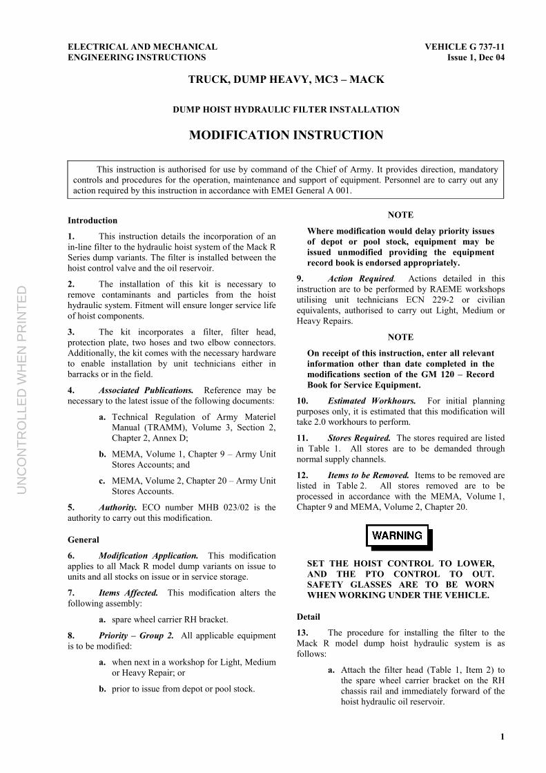
b. Using the protection plate (Table 1, Item 8)as a template, scribe a mark where twoholes will be drilled. Ensure the plate isbutted against the existing frame bracketand the short edge aligned to the edge of thewheel bracket as shown in Figure 1 below.
Figure 1 – Filter Mounting Template
c. Drill two holes in the spare wheel carrierbracket using a 10 mm drill bit.
d. Loosely fit the protection plate and filterhead to the carrier bracket with both bolts toensure correct alignment.
NOTE
The filter head is mounted with the inlet portmarked IN, facing towards the driver’s cabin.
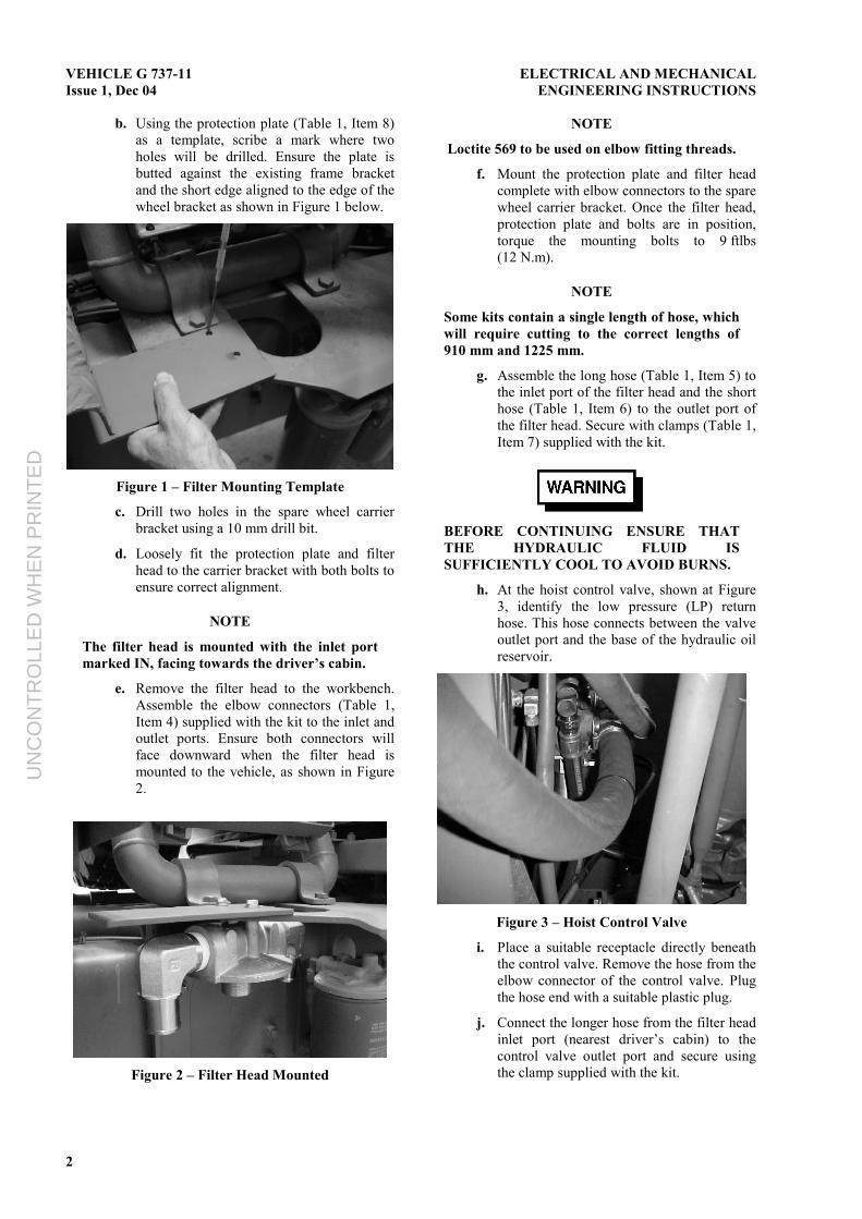
e. Remove the filter head to the workbench.Assemble the elbow connectors (Table 1,Item 4) supplied with the kit to the inlet andoutlet ports. Ensure both connectors willface downward when the filter head ismounted to the vehicle, as shown in Figure2.
Figure 2 – Filter Head Mounted
NOTE
Loctite 569 to be used on elbow fitting threads.
f. Mount the protection plate and filter headcomplete with elbow connectors to the sparewheel carrier bracket. Once the filter head,protection plate and bolts are in position,torque the mounting bolts to 9 ftlbs(12 N.m).
NOTE
Some kits contain a single length of hose, whichwill require cutting to the correct lengths of910 mm and 1225 mm.
g. Assemble the long hose (Table 1, Item 5) tothe inlet port of the filter head and the shorthose (Table 1, Item 6) to the outlet port ofthe filter head. Secure with clamps (Table 1,Item 7) supplied with the kit.
BEFORE CONTINUING ENSURE THATTHE HYDRAULIC FLUID ISSUFFICIENTLY COOL TO AVOID BURNS.
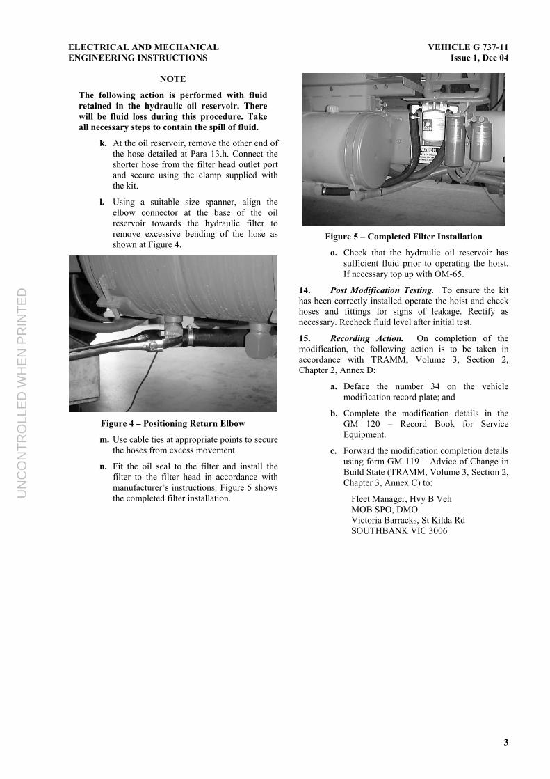
h. At the hoist control valve, shown at Figure3, identify the low pressure (LP) returnhose. This hose connects between the valveoutlet port and the base of the hydraulic oilreservoir.
Figure 3 – Hoist Control Valve
i. Place a suitable receptacle directly beneaththe control valve. Remove the hose from theelbow connector of the control valve. Plugthe hose end with a suitable plastic plug.
j. Connect the longer hose from the filter headinlet port (nearest driver’s cabin) to thecontrol valve outlet port and secure usingthe clamp supplied with the kit.
UN
CO
NT
RO
LLE
D W
HE
N P
RIN
TE
D
ELECTRICAL AND MECHANICALENGINEERING INSTRUCTIONS
VEHICLE G 737-11Issue 1, Dec 04
3
NOTE
The following action is performed with fluidretained in the hydraulic oil reservoir. Therewill be fluid loss during this procedure. Takeall necessary steps to contain the spill of fluid.
k. At the oil reservoir, remove the other end ofthe hose detailed at Para 13.h. Connect theshorter hose from the filter head outlet portand secure using the clamp supplied withthe kit.
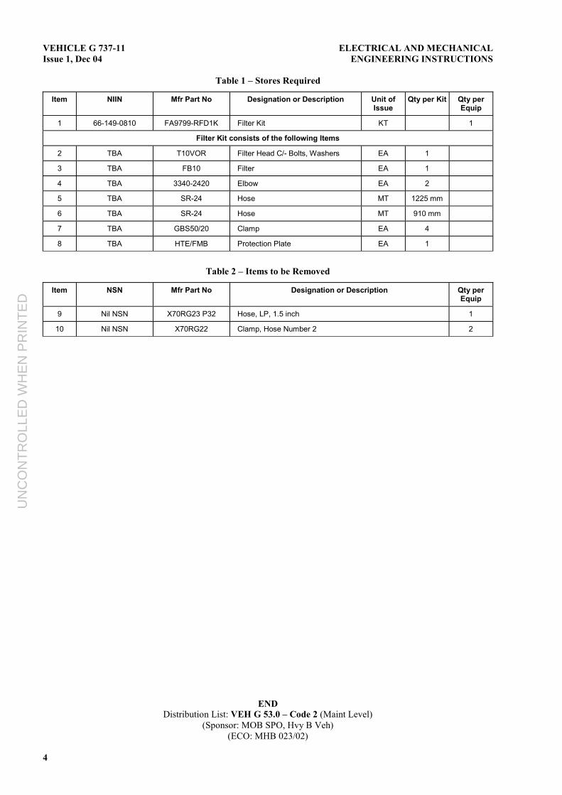
l. Using a suitable size spanner, align theelbow connector at the base of the oilreservoir towards the hydraulic filter toremove excessive bending of the hose asshown at Figure 4.
Figure 4 – Positioning Return Elbow
m. Use cable ties at appropriate points to securethe hoses from excess movement.
n. Fit the oil seal to the filter and install thefilter to the filter head in accordance withmanufacturer’s instructions. Figure 5 showsthe completed filter installation.
Figure 5 – Completed Filter Installation
o. Check that the hydraulic oil reservoir hassufficient fluid prior to operating the hoist.If necessary top up with OM-65.
14. Post Modification Testing. To ensure the kithas been correctly installed operate the hoist and checkhoses and fittings for signs of leakage. Rectify asnecessary. Recheck fluid level after initial test.
15. Recording Action. On completion of themodification, the following action is to be taken inaccordance with TRAMM, Volume 3, Section 2,Chapter 2, Annex D:
a. Deface the number 34 on the vehiclemodification record plate; and
b. Complete the modification details in theGM 120 – Record Book for ServiceEquipment.
c. Forward the modification completion detailsusing form GM 119 – Advice of Change inBuild State (TRAMM, Volume 3, Section 2,Chapter 3, Annex C) to:
Fleet Manager, Hvy B VehMOB SPO, DMOVictoria Barracks, St Kilda RdSOUTHBANK VIC 3006
UN
CO
NT
RO
LLE
D W
HE
N P
RIN
TE
D
VEHICLE G 737-11Issue 1, Dec 04
ELECTRICAL AND MECHANICALENGINEERING INSTRUCTIONS
4
Table 1 – Stores Required
Item NIIN Mfr Part No Designation or Description Unit ofIssue
Qty per Kit Qty perEquip
1 66-149-0810 FA9799-RFD1K Filter Kit KT 1
Filter Kit consists of the following Items
2 TBA T10VOR Filter Head C/- Bolts, Washers EA 1
3 TBA FB10 Filter EA 1
4 TBA 3340-2420 Elbow EA 2
5 TBA SR-24 Hose MT 1225 mm
6 TBA SR-24 Hose MT 910 mm
7 TBA GBS50/20 Clamp EA 4
8 TBA HTE/FMB Protection Plate EA 1
Table 2 – Items to be Removed
Item NSN Mfr Part No Designation or Description Qty perEquip
9 Nil NSN X70RG23 P32 Hose, LP, 1.5 inch 1
10 Nil NSN X70RG22 Clamp, Hose Number 2 2
ENDDistribution List: VEH G 53.0 – Code 2 (Maint Level)
(Sponsor: MOB SPO, Hvy B Veh)(ECO: MHB 023/02)
UN
CO
NT
RO
LLE
D W
HE
N P
RIN
TE
D