Modicon Modbus TCPIP Driver Guide - Microsoft · PDF fileWebAccess Device Driver Guide Modicon...
45
WebAccess Device Driver Guide Modicon Modbus TCP/IP Modbus TCP/IP / Modicon Ethernet Device Driver Guide Version 4.5 rev 0 Broadwin Technology, Inc. page 1-1
Transcript of Modicon Modbus TCPIP Driver Guide - Microsoft · PDF fileWebAccess Device Driver Guide Modicon...

WebAccess Device Driver Guide Modicon Modbus TCP/IP
Modbus TCP/IP / Modicon Ethernet Device Driver Guide
Version 4.5 rev 0 Broadwin Technology, Inc. page 1-1

WebAccess Device Driver Guide Modicon Modbus TCP/IP
Table of Contents
Modbus TCP/IP / Modicon Ethernet Device Driver Guide 1-1
1. Modbus TCP/IP Device Communications 3 1.1 Introduction to Modbus Ethernet /TCPIP............................................ 3
1.1.1 Modbus Ethernet / TCP/IP .................................................... 3 1.1.2 Ease of Use: Parameters ...................................................... 4 1.1.3 Redundant Comports ............................................................ 4 1.1.4 Modbus Protocols.................................................................. 4
1.1.4.1 Modbus Ethernet / TCP/IP .................................................. 4 1.1.4.2 Modbus RTU ....................................................................... 5 1.1.4.3 Modbus ASCII ..................................................................... 5
1.2 Configure Modicon / Modbus TCIP device......................................... 5 1.3 TCPIP Comport Properties................................................................. 7
1.3.1 Comport Number ................................................................... 7 1.3.2 Description............................................................................. 7 1.3.3 Scan Time ............................................................................. 7 1.3.4 Timeout.................................................................................. 8 1.3.5 Retry Count ........................................................................... 9 1.3.6 Auto Recover Time................................................................ 9 1.3.7 Backup Port ........................................................................... 9
1.4 Device Properties - Modicon ............................................................ 10 1.4.1 Device Name ....................................................................... 11 1.4.2 Description........................................................................... 12 1.4.3 Unit Number ........................................................................ 12 1.4.4 Device Type......................................................................... 12 1.4.5 Com Port ............................................................................. 12 1.4.6 Unit Number ........................................................................ 12 1.4.7 Device Address ................................................................... 12
1.4.7.1 Multiple Devices with same Device Address .................... 13 1.5 Configure a Tag................................................................................ 13 1.6 Step by Step Guide .......................................................................... 14
1.6.1 Task 1: Configure a Communication Port ........................... 15 1.6.2 Task 2: Add Device (a PLC)................................................ 18 1.6.3 Task 3: Add an Analog Input Tag........................................ 21 1.6.4 Task 4: Add an Analog Output Tag ..................................... 24 1.6.5 Task 5: Add a Discrete Output (also called Digital Output). 28 1.6.6 Task 6: Download changes to the SCADA Node................ 31 1.6.7 Task 7: Start the SCADA Node via Project Manager.......... 33 1.6.8 Task 8: Start VIEW to verify communications to PLC......... 35 1.6.9 Task 9: Use Point Info (Tag Browser) to verify new tag...... 37 1.6.10 Task 10: Review the Port and Device List........................... 39
1.7 Addendum ........................................................................................ 42 1.7.1 Device Failure...................................................................... 42 1.7.2 Troubleshooting an asterisk (*) ........................................... 42 1.7.3 Use Station Status to diagnose problems ........................... 43
Version 4.5 rev 0 Broadwin Technology, Inc. page 1-1

WebAccess Device Driver Guide Modicon Modbus TCP/IP
July 30, 2005
Version 4.5 rev 0 Broadwin Technology, Inc. page 1-2

WebAccess Device Driver Guide Modicon Modbus TCP/IP
1.
1.1
1.1.1
Modbus TCP/IP Device Communications
Introduction to Modbus Ethernet /TCPIP WebAccess SCADA Node provides a Modbus master interface using Modbus RTU protocol for communicating with Modbus slave devices. Slave devices include AEG/Modicon 984 and Quantum PLCs, GE Fanuc Series-6, Series-5, Series-90, and many others.
The Modicon driver accesses real-time data and control automation equipment with Modbus RTU protocol.
Modbus is a "De-facto" standard for communications. Modbus is an "open" communications protocol designed for industrial control and monitoring applications. Programmable Logic Controllers (PLC), Single Loop and Multi-Loop Controllers, Remote Terminal Units (RTU, Distributed control Systems (DCS), computers, shop floor operator panels and other devices can communicate throughout plants and substations via Modbus RTU or Modbus Ethernet network.
Especially for connection of SCADA and HMI systems to intelligent operator panels, PLCs and controllers, Modbus became a de-facto standard. Many automation devices support the Modbus protocol in both Serial Modbus RTU and Modbus Ethernet.
Modbus Ethernet / TCP/IP The WebAccess Modicon Modbus Device Driver can communicate with either TCP/IP communications (or RS-232, RS-422 or RS-485 as a backup) using a packet version of the Modbus RTU protocol. Any TCP/IP compatible medium is acceptable, the most common being Ethernet.
The WebAccess COM Ports are “virtual” in the WebAccess configuration for Modbus TCP/IP. The WebAccess driver will search all NIC (network Interface Cards) to find the addressed devices regardless of the configured Comport. For the Modbus TCP/IP driver, it is recommended to use a Com Port that does not utilize an actual Serial COM port.
The computer communication port must be designed for use with the Windows 32-bit operating system.
Modicon's Modbus TCP/IP network is a single master, multi-drop network, which supports up to 247 slave devices.
Version 4.5 rev 0 Broadwin Technology, Inc. page 3

WebAccess Device Driver Guide Modicon Modbus TCP/IP
WebAccess can scan every 100 milliseconds over TCP/IP connections limited only by the PLC, Controller or RTU and the network connection.
The Genuine WebAccess Modbus Driver is among the fastest Modbus TCP/IP drivers available, if not the fastest.
1.1.2
1.1.3
1.1.4
1.1.4.1
Ease of Use: Parameters Like all Genuine WebAccess drivers, object-oriented "parameters" guide novice users with pre-built templates containing typical addresses.
AI is an Analog Input (30001 to 39999 range of addresses). These are typically read only numbers from the PLC.
AO is an Analog Output (40001 to 49999 range of addresses). These are typically values written to the PLC by operators and programs. Setpoints, Outputs, alarm limits are examples.
DI is a Digital Input (00001 to 09999 range of addresses). These are typically read only statuses (On, Off, True, False, etc) from the PLC.
DO is a Digital Output (10001 to 19999 range of addresses). These are typically values written to the PLC by operators and programs. On/ OFF, RUN/STOP are examples.
Users can select a parameter type, and then modify the address to the correct register in order to build a tag.
Redundant Comports WebAccess supports redundant Comports. Two Ethernet comports can be used, the second acts as a backup to the first. The WebAccess COM Ports are “virtual” in the WebAccess configuration for Modbus TCP/IP. The WebAccess driver will search all NIC (network Interface Cards) to find the addressed devices regardless of the configured Comport. A Backup port does not need to be specified. However, a second IP address for the PLC must be specified (i.e. the PLC must have two Network Interface cards).
Modbus Ethernet can also be backed up with a Serial connection (and vice versa). The Backup port must be specified as the actual Serial Comport (usually COMPORT 1 or 2).
Modbus Protocols
Modbus Ethernet / TCP/IP
Modicon's Modbus Ethernet network is a single master, multi-drop network, which supports up to 247 slave devices. The preferred physical layer for the Modbus Ethernet network TCP/IP over Ethernet, although any TCP/IP network connection is supported including the Internet, WANs and LANs. A single IP address can support up to 255 devices. Serial communications can be
Version 4.5 rev 0 Broadwin Technology, Inc. page 4

WebAccess Device Driver Guide Modicon Modbus TCP/IP
"encapsulated" into TCP/IP packets using Modbus Serial-to-Ethernet gateways.
The main advantage of Modbus TCP/IP is the greater character density and greater network speed allows better data throughput than Modbus RTU or ASCII.
1.1.4.2
1.1.4.3
1.2
Modbus RTU
The Modbus Serial RTU is described in another User Guide.
This is the default protocol of the WebAccess Modicon serial device driver. In Modbus RTU, each eight-bit byte, in a message, contains two four-bit hexadecimal characters. The main advantage of Modbus RTU is the greater character density allows better data throughput than Modbus ASCII for same baud rate.
WebAccess can scan every 100 milliseconds over serial connections limited only by the PLC, Controller or RTU and the connection.
Most modern Modbus serial devices use Modbus RTU.
Modbus ASCII
The Modbus Serial ASCII Driver is described in another User Guide.
This is an option to the Modicon protocol of the WebAccess Modicon serial device drive.
In Modbus ASCII, each eight-bit byte, in a message, is sent as two ASCII characters. The main advantage is that it allows time intervals of up to one second to occur between characters without causing an error.
Configure Modicon / Modbus TCIP device
The steps, in summary, are:
1. Start Internet Explorer Web Browser. 2. Enter IP address of the Project Node. 3. Use WebAccess Configuration. 4. Open or Create a Project. 5. Configure a SCADA node (the PC that will connect to the automation
hardware). 6. Configure a Comport for the SCADA Node that is a TCPIP type
Comport.
Note - It is recommended to select a Comport number greater than 2 so that it does not conflict with a Serial comport that you may want to use later.
Version 4.5 rev 0 Broadwin Technology, Inc. page 5

WebAccess Device Driver Guide Modicon Modbus TCP/IP
7. Configure a Scan time and Timeout for the Com Port. 8. Configure a Modicon Device (determines the communications
Protocol or Device Driver) using Add Device 9. Configure IP Address, Port Number, Unit Number and Device Number
to match those in the PLC.
Note – Many Modbus Ethernet devices ignore the Device Number if there is only one device at a given IP Address. Device Number = 0 uses the Unit Number as the Device Number. The Unit Number is used for display purposes in WebAccess. The Device Number is used by the communications protocol to the device.
10. Refer to later sections in this guide for other fields (they usually are
not needed). 11. Use Add Tag or Add Block to create tags. 12. Select a Parameter (AI, AO, DI, DO) to match the type of data to be
read (Analog Input, Analog Output, Digital Input, Digital Output). The Address of the data must match the Parameter Type:
AI is an Analog Input (30001 to 39999 range of addresses). These are typically read only numbers from the PLC.
AO is an Analog Output (40001 to 49999 range of addresses). These are typically values written to the PLC by operators and programs. Setpoints, Outputs, alarm limits are examples.
DI is a Digital Input (00001 to 09999 range of addresses). These are typically read only statuses (On, Off, True, False, etc) from the PLC.
DO is a Digital Output (10001 to 19999 range of addresses). These are typically values written to the PLC by operators and programs. On/ OFF, RUN/STOP are examples.
13. Modify the Address to match the actual address. 14. Apply a Tag name. 15. Edit Tags in Project Manager to assign Alarms, Scaling, Engineering
Units, Description and other features.
Version 4.5 rev 0 Broadwin Technology, Inc. page 6

WebAccess Device Driver Guide Modicon Modbus TCP/IP
1.3
1.3.1
1.3.2
1.3.3
TCPIP Comport Properties The TCPIP Comport is usually associated with an Ethernet Network Interface Card on the SCADA Node PC. Any TCPIP compatible medium is supported as long as it complies with Microsoft TCPIP protocol stack.
Figure 1.1 TCPIP Comport properties
Comport Number The WebAccess COM Ports are “virtual” in the WebAccess configuration for TCP/IP. The WebAccess driver will search all NIC (Network Interface Cards) to find the addressed devices regardless of the configured Comport.
For the Modbus TCP/IP driver, it is recommended to use a Com Port number greater then 2 and that does not utilize an actual Serial com port (e.g. COM1, COM2, etc) on the SCADA Node.
Description This is an optional field used for user reference.
Scan Time This is the time in milliseconds to scan the PLC. This must match the ability of the PLC to respond.
Version 4.5 rev 0 Broadwin Technology, Inc. page 7

WebAccess Device Driver Guide Modicon Modbus TCP/IP
Version 4.5 rev 0 Broadwin Technology, Inc. page 8
If the PLC cannot respond as fast as the SCAN Time entered, WebAccess will scan at a slower rate.
Scan Time is also network dependant, it is possible to enter a Scan Time faster than your network can respond, WebAccess will poll all devices and tags on the Comport before starting a new scan.
1.3.4 Timeout Timeout is the time waited before re-sending a communications packet that did not have a reply.
Timeout specifies how long the software waits for a response to a data request, specifically to wait for a reply from one packet. A recommended value is 7 to 10 ticks, longer if the communication device is slow. This is protocol dependent: some protocols do not allow changes in time out.
Combined with Retry count, Timeout also determines time to consider a device or port as BAD. Timeout is the time to wait since last communication packet sent without a reply. Time is in milliseconds. The slow or poor quality communications require longer timeout. The faster the communications network or device, the shorter the timeout required. Shorter timeouts notify operators of communications failure more quickly.
TimeOut, multiplied by Retry Count plus scan time, is how long WebAccess will wait before it considers a device bad. WebAccess will send a packet, wait for the TimeOut for a reply. If retry count is non-zero, WebAccess will repeat the request, wait the Timeout, and repeat for the number of Retry Times. A device is marked Bad (or Failed) after the number of Retries fail.
In the example above, Scan Time is 1 second, Retry Count is 3, and Timeout is 200, WebAccess will:
• Waits 1 second
• Send a packet.
• Wait 200 Milliseconds for a reply.
• Send a packet again if no reply.
• Wait 200 Milliseconds.
• Send A Packet a third Time if no reply
• Wait 200 Milliseconds.
• Mark the device Bad (Failed) if no reply.
In the above example, after approximately 1 + .6 seconds after a device fails, WebAccess will mark it bad.
WebAccess Device Driver Guide Modicon Modbus TCP/IP
1.3.5
1.3.6
1.3.7
Retry Count Number of times to retry communications if no reply is received from a device. Combined with Timeout, also determines time to consider a device or port as BAD.
In addition, Indicates the number of times after the first attempt has failed that communication should be attempted before indicating a failure. Specifically, how many times to send a single packet after the field device fails to respond to the first packet. After the retry count is exceeded, all the tags in the packet are marked with asterisks and the next packet of requests is sent. A reasonable value is 3 to 5 times. After this number of tries, the tags in this packet are marked as "fail to respond" (i.e. asterisks) and are disabled. In reality, increasing the number of retries hides failures on the part of the field device to respond to a request. Essentially, increasing the retries gives the field device more chances to reply.
Auto Recover Time Auto Recover Time is the time to wait after a Device is marked Bad (or Failed) before re-initializing communications. WebAccess will mark the device good, send a packet and begin the whole retry / timeout process above.
In the above example fro Timeout, WebAccess will wait 1 minute after a device fails before retrying communications. Every One minute the device will go Good, 1.6 seconds later it will be marked Bad if it is still failed, repeat.
If communications to the PLC is unusually slow due to hardware, communications or network issues, you might consider increasing this value. If communications to the PLC or RTU fails frequently, you may want to decrease this number in order to have WebAccess try to re-establish communications sooner.
If communications to the PLC, RTU or device Fails (i.e. exceeds Timeout) WebAccess will wait the Auto Recover Time before trying to re-establish communications.
Backup Port This enables a redundant communications path to the Device. If communications cannot be established through this Comport, WebAccess will try a second Comport, specified as the Backup Port. You must configure the backup Port number in WebAccess, but without any devices on it. Usually the device must have two comports also. Not all Device Types support a backup Port.
The Backup Port is usually configured as the same type. However, some Device Types allow the backup port to be another physical type; for example, Modicon Device can use a Serial Port as a backup port to TCP/IP (network) port. The PLC must have both TCPIP Interface and a Serial Interface connected to the SCADA node, in this example.
Version 4.5 rev 0 Broadwin Technology, Inc. page 9

WebAccess Device Driver Guide Modicon Modbus TCP/IP
1.4 Device Properties - Modicon Add your device to the TCPIP Port, by selecting the Serial Port you have configured, then select Add Device.
To modify an existing Device, Select Device Properties. The Device Properties Page for a Serial Type Device appears.
Figure 3-12Modicon - Modbus TCPIP device
Device Name is any user-defined name. See Device Name for more information.
Description is a user defined. See Description for more information.
Unit Number usually corresponds to the device address number. Unit Number is used for display purposes in WebAccess. Device Number = 0 uses the Unit Number as the Device Number. The Device Number is used by the communications protocol to the device.
Version 4.5 rev 0 Broadwin Technology, Inc. page 10

WebAccess Device Driver Guide Modicon Modbus TCP/IP
Many Modbus Ethernet devices ignore the Device Number if there is only one device at a given IP Address. The Device Type is Modicon.
Device Type Modicon. WebAccess uses the official version the Modbus TCPIP specified by the inventors of Modbus, MODICON.
IP Address is the IP Address of the PLC, RTU or other device you are establishing communications with. The Primary IP Address must be specified. The Secondary IP Address is used only if the PLC or device has redundant communication cards (i.e. two NICs in the PLC).
Port Number is the TCP Port (or UDP port) of the PLC. The Primary must be specified. The Secondary is used only if a Secondary IP address is used.
Device Address is the Modbus Device Address (0 - 255) used by the Modbus RTU protocol. How this is handled varies by device / manufacturer. Many Modbus TCP/IP devices ignore this Device Address (the Modbus RTU Address). Some Modbus TCP/IP devices have multiple PLCs/ RTUs at the same IP Address, and use the Device Address to route to the correct PLC sharing the same IP address.
Use UDP: The default protocol of the WebAccess TCP/IP driver is TCP. However, some devices use UDP. If the PLC or Device uses UDP, then you must specify Use UDP = 1 for the WebAccess configuration of this device.
Packet Delay (ms): Some devices cannot receive very fast request after they respond previous packet. A delay may be required for the next request from WebAccess for those slow devices, especially for some old power meters.
Digital block size: Some Modbus compatible devices use only a certain part of a Modbus address or only handle a short data range for data request from client. WebAccess allows users to define the maximum data block size for both requested Digital and Analog type data.
Analog block size: Some Modbus compatible devices use only a certain part of a Modbus address or only handle a short data range for data request from client. WebAccess allows users to define the maximum data block size for both requested Digital and Analog type data.
1.4.1 Device Name A Device is a PLC, Controller, VAV or other automation hardware or software entity. Device name is a User-assigned name that will appear in the Project Manager (Configuration Tool) and in runtime VIEW Displays. Choosing a descriptive Name can help technicians identify the location of your device.
Changing only the Device Name will rename the existing device.
Changing both the Device Name and the Unit Number will make a copy of the device (e.g. create another device).
Version 4.5 rev 0 Broadwin Technology, Inc. page 11

WebAccess Device Driver Guide Modicon Modbus TCP/IP
1.4.2
1.4.3
1.4.4
1.4.5
1.4.6
1.4.7
Description User assigned description up to 70 characters
Unit Number For Modbus, this must correspond to the Unit Number used in the protocol addressing. This is the address configured in the device or by a dipswitch on the device. The range of Unit Number is 0 to 255 for Modbus.
This Unit Number will appear on the System Status Display, Point Detail, user-built displays and tags to reference the status of this device.
Changing only the Unit Number here will change the existing device.
Changing both the Device Name and the Unit Number will make a copy of the device (e.g. create another device).
Device Type This is the communication Driver used to communicate with all devices on this Com Port. Only one communications protocol is supported on the same COM port. Once a Device Type is created on a COM port, the Device Type of additional devices will be limited to this Device Type.
To use another communications device, you must configure another COM port. Multiple TCP/IP type Com Ports can be added which use the same TCP/IP Network Card on your PC.
Com Port Com Port is the WebAccess COM Port Number. If it is a TCP/IP type Port, WebAccess will search all network Cards on your SCADA Node PC. You can assign multiple IP Addresses to your SCADA Node Network card and use a single Network card on your SCADA Node. You can use multiple TCP/IP type Com Ports in WebAccess with only a single Network Card on the SCADA Node.
Unit Number Unit Number is the Unit Number used by WebAccess. The Project Manager will force you to use a unique unit number for each Comport. There can be multiple PLCs/RTUs on the same comport, each with a unique Unit Number. There cannot be multiple PLC's / RTU's on the same Com Port with the same Unit Number.
Device Address Device Address is the Modbus Device Address (0 - 255) used by the Modbus RTU protocol. How this is handled varies by device / manufacturer. Many Modbus TCP/IP devices ignore this Device Address (the Modbus RTU Address). Some Modbus TCP/IP devices have multiple PLCs/ RTUs at the same IP Address, and use the Device Address to route to the correct PLC sharing the same IP address.
Version 4.5 rev 0 Broadwin Technology, Inc. page 12

WebAccess Device Driver Guide Modicon Modbus TCP/IP
If the Device Address is 0, WebAccess uses the Unit Number as the Device Address.
1.4.7.1
1.5
Multiple Devices with same Device Address
If you have multiple devices with the same Device Address (e.g. Modbus RTU address 0 - 255), your options are:
1. Configure a Different WebAccess Unit Number for each device and enter the actual Device Address in the Device Address Field.
2. Configure Multiple Comports and place the devices on separate comports so that each comport has no device with the same Unit Number. (This is especially true if the device address is 0).
Auto Recover Time is the time to wait after a Device is marked Bad (or Failed) before re-initializing communications. WebAccess will mark the device good, send a packet and begin the whole retry / timeout process above. In the above example, WebAccess will wait 1 minute after a device fails before retrying communications. Every One minute the device will go Good, 1.6 seconds later it will be marked Bad if it is still failed, repeat.
Configure a Tag
Summary of steps
This example is to configure two Tags that read an Analog Input (Address 30003) and an Analog Output (Address 40015).
1. Open Internet Explorer.
2. Connect to Project Node.
3. Start WebAccess Configuration.
4. Select Project.
5. Select SCADA Node.
6. Select the Modicon Device.
7. Select Add Tag.
8. From Parameter Pull Down List Select AI. This will configure an Analog Input. Wait for the Page to update.
Version 4.5 rev 0 Broadwin Technology, Inc. page 13

WebAccess Device Driver Guide Modicon Modbus TCP/IP
9. Optionally, select ALARM from the ALARM pulldown list. Wait for the Page to update with a PINK highlight around alarm (an additional Alarm Fields at bottom of page).
10. Enter a Tagname users can use to identify this Analog Input measurement. For example, if this is a Flow measurement, enter Flow1.
11. Edit the Address to the actual address. From the example, Enter: 30003
12. Enter a Description. This will help identify this tag to Users and Operators. For example, enter Boiler #1 Steam Flow.
13. Optionally enter, Scaling, Span Hi, Span Low, Engineering Units, and Alarms; enable data logging, etc.
14. Press Submit.
15. From Parameter Pull Down List Select AO. This will configure an Analog Output. Wait for the Page to update.
16. Optionally, select ALARM from the ALARM pulldown list. Wait for the Page to update with a PINK highlight around alarm (and additional Alarm Fields at bottom of page).
17. Enter a Tagname users can use to identify this Analog Output measurement. For example, if this is a signal to a Valve, enter Valve1.
18. Edit the Address to the actual address. From the above example, Enter: 40015
19. Enter a Description. This will help identify this tag to Users and Operators. For example, enter Boiler #1 Steam Valve.
20. Optionally enter, Scaling, Span Hi, Span Low, Output Limits, Engineering Units, and Alarms; enable data logging, etc.
21. Press Submit.
Congratulations! You have just configured a Measurement and Output Tags to Modbus device.
1.6 Step by Step Guide It is recommended to use a Modbus PLC with TCP/IP communications. If a PLC is not available, it is recommended to install the Modbus TCP Simulator software on the student’s PC. See the Appendix for more information on the Modbus PLC simulator software.
Version 4.5 rev 0 Broadwin Technology, Inc. page 14

WebAccess Device Driver Guide Modicon Modbus TCP/IP
1.6.1 Task 1: Configure a Communication Port From the Project Manager (See 2.3.2 Connect to Project Node of the Engineering Manual, if you need help connecting)
1. Select your SCADA node under the Project/Node list.
2. Select Add Comport
This can take a long time while tables are created in the database on the Project Node / Web Server.
Warning – if multiple students are using a single project node that is using a 10-client limit for IIS, pressing Add Comport will open a new connection each time it is pressed. Be patient if you are sharing a Project Node with other students and do not press Add Comport more than once, otherwise you will get the error:
The page cannot be displayed
There are too many people accessing the Web site at this time.
3. The Create New Comport page appears.
Version 4.5 rev 0 Broadwin Technology, Inc. page 15

WebAccess Device Driver Guide Modicon Modbus TCP/IP
4. Select the TCP/IP as the Interface Name for this Comport. (Also called the Comport Type).
The fields change depending on the Comport Type.
5. The TCP/IP Comport Properties page appears.
Version 4.5 rev 0 Broadwin Technology, Inc. page 16

WebAccess Device Driver Guide Modicon Modbus TCP/IP
TCPIP - TCP/IP (transmission Control Protocol / Internet Protocol). Specifies a "Virtual Port" that uses the TCP/IP service installed. Does not correspond to specific IO card or comport number. Will access any IO card that uses the TCP/IP service installed on your PC. For a description of the data entry fields for a TCP/IP Network Interface see the Engineering Manual, section 3.3.4 TCP/IP Com Port Properties.
6. Enter a Comport Number. It is recommended to use a number above 2 for TCP/IP ports, so you don't interfere with adding a serial comport. Most PCs have 2 serial comports, if you configured a TCP/IP comport as 1 or 2, you would not be able to use that serial comport in the future. It is not easy to change comport numbers.
7. Optionally, enter a Description. This is just for your own reference.
8. Enter a Scan Time and select the radio button for the units (Millisecond, Second, Minute or Hour).
All devices are scanned at the same frequency on a given comport. All Constant Scan type Tags are scanned at the same frequency on a comport. Display Scan Tags are scanned at this same frequency, but only when they appear on a Display.
9. Accept the default values for the other fields, or modify them. For a description of the data entry fields for a TCP/IP Network Interface see, section 3.3.4 TCP/IP Com Port Properties.
10. Click Submit.
11. The SCADA Node page appears. The Port should appear as a folder under the SCADA node. (In this example Port 3 under Node 1) in the menu tree at left.
Version 4.5 rev 0 Broadwin Technology, Inc. page 17

WebAccess Device Driver Guide Modicon Modbus TCP/IP
1.6.2 Task 2: Add Device (a PLC) 12. Click on the Port hyperlink (Port3 in this example). The Com Port
Properties page opens.
13. Select Add Device.
14. The Create Device Page opens. This also can take some time while data tables are created in the database on the Project Node.
Version 4.5 rev 0 Broadwin Technology, Inc. page 18

WebAccess Device Driver Guide Modicon Modbus TCP/IP
15. Select Modicon form the Device Type pull down list.
(Alternatively, you can select one of the other Modbus TCP/IP devices: ADAM 5000 Ethernet driver (ADAM5KE), ADAM 6000 (ADAM6K) or Wago 750.
16. Enter a Device Name. This will appear as a folder under the comport in the Project Manager. It will also appear in VIEW during runtime in the Point Detail Display for any tags created.
17. Optionally, enter a description.
18. Enter the Unit Number. This number will appear in VIEW during runtime on the Station Status display and will be the reference to Enable and Disable communications to the Device. It also will be the reference for communication alarms. (1 to 254)
Logically, this usually matched the actual device number, but it is possible to assign a unit number that does not match the actual Modbus Protocol Device Address. For example, each Modbus PLC has a unique IP Address and all PLCs have Modbus Device address 1 at these unique IP Addresses.
19. Enter an IP Address for the Device.
Version 4.5 rev 0 Broadwin Technology, Inc. page 19

WebAccess Device Driver Guide Modicon Modbus TCP/IP
Important! – Use the IP Address and Port given by your Instructor for the PLC in your classroom. The Modbus TCP Simulator software can be installed locally on a SCADA node and use the SCADA nodes IP address.
If you installed the ModSim.exe simulator software on your PC, then enter the IP Address of your PC or 127.0.0.1
20. Enter the TCP or UDP Port Number for the Device.
Important! – Use the TCP Port given by your Instructor for the PLC in your classroom. The Modbus TCP Simulator software uses port 5111.
21. Enter a Device Address if different from the Unit Number.
Important! – Use the Device Address given by your Instructor for the PLC in your classroom. The Modbus TCP Simulator software uses Device Address 1.
22. Optionally, add Address and Port information for a redundant communication path to the Device. For example, if the PLC has two Network Interface Cards (NICs).
23. If using TCP (the official Modbus Ethernet protocol) use 0 for Use UDP.
24. Press Submit. This can be a wait while data tables are created on the Project Node.
The PLC appears as a folder under the comport in Project Manager.
Version 4.5 rev 0 Broadwin Technology, Inc. page 20

WebAccess Device Driver Guide Modicon Modbus TCP/IP
1.6.3 Task 3: Add an Analog Input Tag 25. The Update Device Page Appears.
26. Select Add Tag.
Version 4.5 rev 0 Broadwin Technology, Inc. page 21

WebAccess Device Driver Guide Modicon Modbus TCP/IP
Note – Use the IP Address the Instructor gives you for the PLC in the class
27. The Create New Tag page appears.
28. Use the AI Parameter from the Parameter pull down List
29. Enter a Tagname (AI0002 in the example).
30. Modify the address (30002 in the example).
Version 4.5 rev 0 Broadwin Technology, Inc. page 22

WebAccess Device Driver Guide Modicon Modbus TCP/IP
32. Accept the default values for the other fields. Press Submit.
Important! – Press SUBMIT before continuing to next step or you will loose your data.
For more information, see Section 4.2 Analog Tag Properties in the Engineering Manual.
Version 4.5 rev 0 Broadwin Technology, Inc. page 23

WebAccess Device Driver Guide Modicon Modbus TCP/IP
1.6.4 Task 4: Add an Analog Output Tag 33. Continuing from add Analog Input, the Create New Tag page
appears.
34. Select the AO Parameter from the Parameter Pull Down List.
35. The AO Parameter Page opens.
Version 4.5 rev 0 Broadwin Technology, Inc. page 24

WebAccess Device Driver Guide Modicon Modbus TCP/IP
Notice that the Address field changes from 30001 (for AI) to 40001 (for the AO Parameter).
36. Create a Tag name AO005
Tag name
Tag fields
AO005
Parameter: AO
Description: Valve #5 Position
Address: 40005
Scaling Type: Scale 0 –100% Input to
Version 4.5 rev 0 Broadwin Technology, Inc. page 25

WebAccess Device Driver Guide Modicon Modbus TCP/IP
Span
Span Hi: 100
Span Lo: -100 Output High Limit: 100
Eng Units: %OPEN Display Digits (Integer): 3 All other parameters: use default
Version 4.5 rev 0 Broadwin Technology, Inc. page 26

WebAccess Device Driver Guide Modicon Modbus TCP/IP
37. Press Submit when finished to create the tag.
Important! – Press submit to save your data before continuing with the next step.
Version 4.5 rev 0 Broadwin Technology, Inc. page 27

WebAccess Device Driver Guide Modicon Modbus TCP/IP
1.6.5 Task 5: Add a Discrete Output (also called Digital Output)
38. Select DO from the Parameter pull down list (you have to scroll down to the bottom of the list.
Notice that the Address field Changes to data type changes from analog to discrete. Also, the Data Fields change: State Descriptors appear. There is no Scaling, Span or Output Limits for a Discrete.
Also notice how any data entered is lost if you change the Parameter before pressing submit! It is best to select Parameter before entering tag name. You cannot change the parameter type of a tag once it is created.
Version 4.5 rev 0 Broadwin Technology, Inc. page 28

WebAccess Device Driver Guide Modicon Modbus TCP/IP
39. Select Alarm from the Pulldown list.
Similar to changing the Parameter, selecting alarm changes the page and you will loose any data entered before pressing submit. You can add or remove alarming for a tag after you create.
The page refreshes and alarm fields appear at the top and bottom of the page.
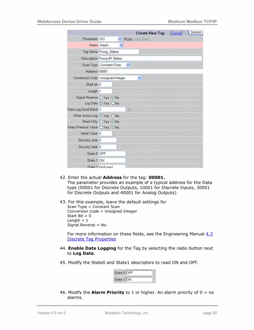
40. Enter a Tag Name of PUMP_STATUS. This will be how the information is referenced on Displays in VIEW. Typical Tag names are YS1001, SS4516, Pump_Start, B31_R11_STATUS. The end user usually has a Tag naming convention used at his facility. Tag name is 21 characters Maximum. For legal tag name characters, see the Engineering Manual section 4.11.1 Legal characters in a Tag Name.
41. Enter a Description of the tag: Pump #1 Status This will appear in VIEW and helps operators identify the information. It will also appear in the Alarm Summary and will be read by the Text-to-Speech Alarm Annunciator. The Description can be changed during runtime by modifying the DESCRP field associated with the tag.
Version 4.5 rev 0 Broadwin Technology, Inc. page 29
WebAccess Device Driver Guide Modicon Modbus TCP/IP
42. Enter the actual Address for the tag: 00001. The parameter provides an example of a typical address for the Data type (00001 for Discrete Outputs, 10001 for Discrete Inputs, 30001 for Discrete Outputs and 40001 for Analog Outputs).
43. For this example, leave the default settings for Scan Type = Constant Scan Conversion Code = Unsigned Integer Start Bit = 0 Length = 1 Signal Reverse = No.
For more information on these fields, see the Engineering Manual 4.3 Discrete Tag Properties
44. Enable Data Logging for the Tag by selecting the radio button next to Log Data.
45. Modify the State0 and State1 descriptors to read ON and OFF.
46. Modify the Alarm Priority to 1 or higher. An alarm priority of 0 = no alarms.
Version 4.5 rev 0 Broadwin Technology, Inc. page 30

WebAccess Device Driver Guide Modicon Modbus TCP/IP
47. Optionally, enable Play Voice to here a Text-to-Speech Alarm annunciation on the SCADA Node.
48. Optionally, enable Send Email and enter your email address in the Email To fields to receive an Alarm Email.
49. In this example, leave the other fields at their default values. For more information on these fields, see the Engineering Manual 4.3 Discrete Tag Properties.
50. Press Submit.
The Tag Name appears under the Device Name in the Project Manager (SCADNode1, Port3, ModbusPLC in this example.) You should see three tags AI0002, AO0005 and PUMP_STATUS.
1.6.6 Task 6: Download changes to the SCADA Node If you have not already done so, connect to the Project Node and Start WebAccess Configuration. Select your Project.
Version 4.5 rev 0 Broadwin Technology, Inc. page 31

WebAccess Device Driver Guide Modicon Modbus TCP/IP
1. Select the SCADA Node under your Project Name in the Project/Node list (Figure 4-31).
Figure 4-31 - SCADA Node Main page (Main.asp) - Download
2. Select Download.
3. The Download Dialog Box pops open (Figure 4-32).
Figure 4-32 - Download SCADA Node
4. When download is finished, select Close Window (Figure 4-32).
5. From Project Manager Select Start node (Figure 4-31).
6. The Start Node Dialog Box pops open (Figure 4-33).
Version 4.5 rev 0 Broadwin Technology, Inc. page 32

WebAccess Device Driver Guide Modicon Modbus TCP/IP
Figure 4-33 - Start SCADA Node
7. When Node is started, select Close Window (Figure 4-33).
Download to the SCADA Node will temporarily STOP the SCADA Node. Users will see a blank screen. Trend and reports will stop collecting data. Communications to field devices will stop. When the SCADA restarts, Alarms will be re-set to unacknowledged.
If you make changes to a Tag, you must download (which will stop and restart the SCADA Node).
Changes to Graphic Displays (and associated Screen Scripts, keymacro files) can be downloaded without stopping the SCADA Node by using Graph Only download link.
1.6.7 Task 7: Start the SCADA Node via Project Manager If you have not already done so, connect to the Project Node and Start WebAccess Configuration. Select your Project.
1. Select the SCADA Node under your Project Name in the Project/Node list.
Figure 4.34 - Start SCADA Node kernel remotely via the Project Manager
Version 4.5 rev 0 Broadwin Technology, Inc. page 33

WebAccess Device Driver Guide Modicon Modbus TCP/IP
2. From Project Manager select Start node.
3. If this is a redundant SCADA node, a dialog box opens asking you to confirm which one or both Primary and Backup should be started.
Figure 4.35 - Appears only if redundant SCADA node.
Use the radio button to unselect a node and the click Submit to continue.
6. The Start Node Dialog Box pops open.
Figure 4.36 – Download Complete and SCADA Node restarted
7. When Node is started, select Close Window.
Warning - if communications times out between the SCADA Node and Project Node, you will still get the above Dialog Box stating the Node has started. You should always start View and connect to that SCADA node to confirm it has started. It may take a long time to start if there are many Data Log files and/or the hard drive is fragmented.
Version 4.5 rev 0 Broadwin Technology, Inc. page 34

WebAccess Device Driver Guide Modicon Modbus TCP/IP
Note – Not all Downloads require restarting the SCADA Node. Only downloading new Tags and new SCADA Node Properties requires the use of the Download from SCADA (which temporarily stops the SCADA Node kernel). Graphics, Scripts, Recipes, the Scheduler and other features can be downloaded from their respective properties page without stopping the SCADA node.
1.6.8 Task 8: Start VIEW to verify communications to PLC Continuing from Step 7 in the previous section (or see Download the SCADA Node in the Engineering Manual).
Figure 4.37- Start VIEW from Project Manger
8. Select Start View (Figure 4-37).
There are other ways to START VIEW described in VIEW Client Options and Start WebAccess VIEW
9. If you have not already installed the Client, you will see a message: "Please Click here to install WebAccess Client first".
Figure 4-38 - Prompt to download and install WebAccess Client
If you get this message, just follow the steps to download and install the client.
Hint - After Downloading Client, close all Web browser windows before running the Client Setup program. If you close all web browser windows, you will not have to reboot your computer.
Version 4.5 rev 0 Broadwin Technology, Inc. page 35

WebAccess Device Driver Guide Modicon Modbus TCP/IP
Figure 4-39 - Login page, start VIEW – from Project Manager
10. Welcome to WebAccess Login appears (Figure 4-39) if the Client is installed.
11. Select Please Login
12. The User Login Dialog Box Appears (Figure 4-40).
Figure 4-40- Login Password Dialog Box
13. Enter Username: admin and no Password:
14. Right Click with the mouse or press the Enter key.
15. The default Main Graphic Display appears (you can edit or create a new Main.bgr later)
Version 4.5 rev 0 Broadwin Technology, Inc. page 36

WebAccess Device Driver Guide Modicon Modbus TCP/IP
Version 4.5 rev 0 Broadwin Technology, Inc. page 37
Figure 4-41 - default MAIN Graphic Display
1.6.9 Task 9: Use Point Info (Tag Browser) to verify new tag The Point Info Dialog Box is opened using:
• Pressing the icon on the Toolbar.
• Pressing Ctrl + F5 on the Keyboard.
• Pressing a Pushbutton that uses the <CTL_F5> keymacro.
• Pressing a Pushbutton that uses the <DIALOG>POINTINFO keymacro.
• Right Click -> Goto -> Point Info (ViewDAQ users skip the right click)

WebAccess Device Driver Guide Modicon Modbus TCP/IP
Figure - Point Info Dialog Box – red is Alarm
16. Scroll down (if necessary) to see the Tag.
17. Click on the Tag Name
18. You should see a ON or OFF as the value. It may be flashing Red if in Alarm.
Version 4.5 rev 0 Broadwin Technology, Inc. page 38

WebAccess Device Driver Guide Modicon Modbus TCP/IP
Troubleshooting
19. If you see an asterisk (*) with a number (typically 8000), communications has failed. You have the IP Address wrong, the port wrong, the address wrong or some other communication problem.
Figure - BAD communications
20. Go to the Station Status Display (see Appendix).
1.6.10 Task 10: Review the Port and Device List The SCADA Node, Ports, Devise, Tags and Blocks are organized in a folder style list at the left of the Project Manger. You may have to open or close a folder to see the information you are looking for.
This section assumes you have started Internet Explorer 6 or later Web Browser and connected to your Project Node.
1. Start WebAccess Configuration.
2. Login with User Name and Password.
3. Select your Project Name.
4. The Project Manger opens.
5. You may need to expand the Port List by clicking on the Folder icon to the left of SCADA Node (Node 1 in the example).
Version 4.5 rev 0 Broadwin Technology, Inc. page 39

WebAccess Device Driver Guide Modicon Modbus TCP/IP
7. You may need to expand the list of Devices under your Comport by
clicking on the Folder icon to the left of the Comport.
8. Drag the slider bar on the left Frame down to reveal Communication Port (e.g. Port 3 in the example above).
9. You may need to expand the list of Devices by clicking on the Folder
icon to the left of the Port (in the example, pick Port3).
10. You may need to expand the list of Tags and Blocks by clicking on
the Folder icon to the left of the device (in the example, pick DemoPLC).
Version 4.5 rev 0 Broadwin Technology, Inc. page 40

WebAccess Device Driver Guide Modicon Modbus TCP/IP
Tags are listed in Black.
Blocks are listed in Brown after all tags.
You may have to scroll down to see the Tag or Block associated with the device.
Version 4.5 rev 0 Broadwin Technology, Inc. page 41

WebAccess Device Driver Guide Modicon Modbus TCP/IP
1.7
1.7.1
1.7.2
Addendum
Device Failure If a PLC or RTU fails, it will not usually affect the other PLCs' or RTUs' communications with WebAccess SCADA node, especially with TCP/IP. WebAccess will mark the Device as Bad (asterisks will appear on displays for Tags with Keep Last Value = No).
If the failed device sends gibberish on the network that somehow blocks communication (unlikely with TCP/IP), a failed device might affect others. This is possible with multi-drop serial connections on a single TCP/IP address, but unlikely.
Troubleshooting an asterisk (*) If you see an asterisk (*) with a number (typically 8000), communications has failed. You have the IP Address wrong, the port wrong, the address wrong or some other communication problem.
Figure - BAD communications
Version 4.5 rev 0 Broadwin Technology, Inc. page 42

WebAccess Device Driver Guide Modicon Modbus TCP/IP
1.7.3 Use Station Status to diagnose problems
The Station Status Display can be viewed from the Toolbar or Ctrl+F7 function key or a pushbutton with the <GOTO>STATION keymacro. The Right-Click Menu can also call up the Action Log (Right Click -> Goto -> Station Status).
Only Power Users and the admin account can view the Station Status through a Web Browser. (General Users and Restricted users cannot view the Station Status through a Web Browser). All users can view the Station Status locally on the SCADA node using ViewDAQ.
The Station Status Display shows status of all communication Ports and automation devices (e.g. stations).
A Communications Alarm will appear in the Status Bar at the bottom of all displays (a Red letter C). See the Engineering Manual, section 7.10 , for more information on the Alarm Windows in the Status Bar.
Figure 4-59 Station Status Display
Using the Ramp Keys , users can change the Comport viewed.
Version 4.5 rev 0 Broadwin Technology, Inc. page 43

WebAccess Device Driver Guide Modicon Modbus TCP/IP
The Numbered pushbuttons (1 through 255) represent the Devices (e.g. Stations) connected to the Comport. These are typically the PLCs, Controllers and automation devices.
A Grey number is not configured (no device configured)
A Blue Number is OK or RETRYING
A Flashing Red is Communication Failure
A Steady Red is DISABLED (by user).
21. If the Device is Blue, this implies you have the Tags Address wrong (e.g. the Modbus Address, 00001, 00002, 00003, etc.)
22. If communication to the Device failed, it will be flashing RED. This implies you have the IP Address, TCP Port or Device Address wrong.
23. Try to ping the PLC Address from the Windows Command prompt. (For more help, see Eng. Manual, 22.2.11 PING to test TCP/IP communications).
24. Confirm the TCP Port and Modbus Device Address from the PLC configurator or Jumper settings on its Network Card (NIC).
Version 4.5 rev 0 Broadwin Technology, Inc. page 44