Modicon M340 with Unity Pro -...
308
35013355.02 www.schneider-electric.com Modicon M340 with Unity Pro Counting Modules User Manual 07/2008 eng
Transcript of Modicon M340 with Unity Pro -...

3501
3355
.02
www.schneider-electric.com
Modicon M340 withUnity ProCounting ModulesUser Manual07/2008 eng

2

Table of Contents
Safety Information . . . . . . . . . . . . . . . . . . . . . . . . . . . . . . . . . . . .9
About the Book . . . . . . . . . . . . . . . . . . . . . . . . . . . . . . . . . . . . . .11
Part I Introduction to the Counting Function. . . . . . . . . . . . . . 13At a Glance . . . . . . . . . . . . . . . . . . . . . . . . . . . . . . . . . . . . . . . . . . . . . . . . . . . . . 13
Chapter 1 General Information on the Counting Function. . . . . . . . . . . .15General Information on Counting Functions . . . . . . . . . . . . . . . . . . . . . . . . . . . . 15
Chapter 2 Presentation of Counting Modules . . . . . . . . . . . . . . . . . . . . . .17At a Glance . . . . . . . . . . . . . . . . . . . . . . . . . . . . . . . . . . . . . . . . . . . . . . . . . . . . . 17General Information about Counting Modules. . . . . . . . . . . . . . . . . . . . . . . . . . . 18Physical Description of the Counting Modules . . . . . . . . . . . . . . . . . . . . . . . . . . 19
Chapter 3 Presentation of the Counting Modules Operation. . . . . . . . . .21At a Glance . . . . . . . . . . . . . . . . . . . . . . . . . . . . . . . . . . . . . . . . . . . . . . . . . . . . . 21General Information about the Counting Modules Operation . . . . . . . . . . . . . . . 22Presentation of the BMX EHC 0200 Counting Module . . . . . . . . . . . . . . . . . . . . 23Overview of BMX EHC 0200 Module Functionalities . . . . . . . . . . . . . . . . . . . . . 25Presentation of the BMX EHC 0800 Counting Module . . . . . . . . . . . . . . . . . . . . 27Overview of BMX EHC 0800 Module Functionalities . . . . . . . . . . . . . . . . . . . . . 29
Part II Counting Modules Hardware Implementation . . . . . . . . 31At a Glance . . . . . . . . . . . . . . . . . . . . . . . . . . . . . . . . . . . . . . . . . . . . . . . . . . . . . 31
Chapter 4 General Rules for Installing Counting Modules . . . . . . . . . . .33At a Glance . . . . . . . . . . . . . . . . . . . . . . . . . . . . . . . . . . . . . . . . . . . . . . . . . . . . . 33Fitting of Counting Modules. . . . . . . . . . . . . . . . . . . . . . . . . . . . . . . . . . . . . . . . . 34Fitting 10-Pin and 16-Pin Terminal Blocks to a BMX EHC 0200 CountingModule. . . . . . . . . . . . . . . . . . . . . . . . . . . . . . . . . . . . . . . . . . . . . . . . . . . . . . . . . 37How to Connect BMX EHC 0200 Module: Connecting 16-Pin and 10-Pin Terminal Blocks . . . . . . . . . . . . . . . . . . . . . . . . . . . . . . . . . . . . . . . . . . . . . . . . . 38Fitting a 20-Pin Terminal Block to a BMX EHC 0800 Counting Module . . . . . . . 39
35013355.02 07/2008 3
How to Connect BMX EHC 0800 Module: Connecting a 20-Pin TerminalBlock . . . . . . . . . . . . . . . . . . . . . . . . . . . . . . . . . . . . . . . . . . . . . . . . . . . . . . . . . . 43
Chapter 5 BMX EHC 0200 Counting Module Hardware Implementation 47At a Glance . . . . . . . . . . . . . . . . . . . . . . . . . . . . . . . . . . . . . . . . . . . . . . . . . . . . . 47
5.1 Characteristics and Diagnostics of the BMX EHC 0200 Module . . . . . . . . . . . . . 48At a Glance . . . . . . . . . . . . . . . . . . . . . . . . . . . . . . . . . . . . . . . . . . . . . . . . . . . . . 48Characteristics for the BMX EHC 0200 Module and its Inputs and Outputs . . . . 49Display and Diagnostics of the BMX EHC 0200 Counting Module . . . . . . . . . . . 51BMX EHC 0200 Module Wiring . . . . . . . . . . . . . . . . . . . . . . . . . . . . . . . . . . . . . . 53
Chapter 6 BMX EHC 0800 Counting Module Hardware implementation 61At a Glance . . . . . . . . . . . . . . . . . . . . . . . . . . . . . . . . . . . . . . . . . . . . . . . . . . . . . 61
6.1 Characteristics and Diagnostics of the BMX EHC 0800 Module . . . . . . . . . . . . . 62At a Glance . . . . . . . . . . . . . . . . . . . . . . . . . . . . . . . . . . . . . . . . . . . . . . . . . . . . . 62Characteristics of the BMX EHC 0800 Module and its Inputs . . . . . . . . . . . . . . . 63Display and Diagnostics of the BMX EHC 0800 Counting Module . . . . . . . . . . . 65BMX EHC 0800 Module Wiring . . . . . . . . . . . . . . . . . . . . . . . . . . . . . . . . . . . . . . 68
Part III Counting Modules Functionalities . . . . . . . . . . . . . . . . . .73At a Glance . . . . . . . . . . . . . . . . . . . . . . . . . . . . . . . . . . . . . . . . . . . . . . . . . . . . . 73
Chapter 7 BMX EHC 0200 Counting Module Functionalities. . . . . . . . . . 75At a Glance . . . . . . . . . . . . . . . . . . . . . . . . . . . . . . . . . . . . . . . . . . . . . . . . . . . . . 75
7.1 BMX EHC 0200 Module Functionalities. . . . . . . . . . . . . . . . . . . . . . . . . . . . . . . . 76At a Glance . . . . . . . . . . . . . . . . . . . . . . . . . . . . . . . . . . . . . . . . . . . . . . . . . . . . . 76Input Interface Blocks . . . . . . . . . . . . . . . . . . . . . . . . . . . . . . . . . . . . . . . . . . . . . 77Programmable Filtering . . . . . . . . . . . . . . . . . . . . . . . . . . . . . . . . . . . . . . . . . . . . 78Comparison . . . . . . . . . . . . . . . . . . . . . . . . . . . . . . . . . . . . . . . . . . . . . . . . . . . . . 79Output Block Functions . . . . . . . . . . . . . . . . . . . . . . . . . . . . . . . . . . . . . . . . . . . . 82Diagnostics . . . . . . . . . . . . . . . . . . . . . . . . . . . . . . . . . . . . . . . . . . . . . . . . . . . . . 88Synchronization, Homing, Enable, Reset to 0 and Capture Functions . . . . . . . . 90Modulo Flag and Synchronization Flag . . . . . . . . . . . . . . . . . . . . . . . . . . . . . . . . 97Sending Counting Events to the Application . . . . . . . . . . . . . . . . . . . . . . . . . . . . 99
7.2 BMX EHC 0200 Module Operation Modes . . . . . . . . . . . . . . . . . . . . . . . . . . . . 102At a Glance . . . . . . . . . . . . . . . . . . . . . . . . . . . . . . . . . . . . . . . . . . . . . . . . . . . . 102BMX EHC 0200 Module Operation in Frequency Mode . . . . . . . . . . . . . . . . . . 103BMX EHC 0200 Module Operation in Event Counting Mode. . . . . . . . . . . . . . . 104BMX EHC 0200 Module Operation in Period Measuring Mode. . . . . . . . . . . . . 106BMX EHC 0200 Module Operation in Ratio Mode. . . . . . . . . . . . . . . . . . . . . . . 109BMX EHC 0200 Module Operation in One Shot Counter Mode . . . . . . . . . . . . 111BMX EHC 0200 Module Operation in Modulo Loop Counter Mode. . . . . . . . . . 115BMX EHC 0200 Module Operation in Free Large Counter Mode . . . . . . . . . . . 119BMX EHC 0200 Module Operation in Pulse Width Modulation Mode . . . . . . . . 128
Chapter 8 BMX EHC 0800 Counting Module Functionalities. . . . . . . . . 131
4 35013355.02 07/2008

At a Glance . . . . . . . . . . . . . . . . . . . . . . . . . . . . . . . . . . . . . . . . . . . . . . . . . . . . 1318.1 BMX EHC 0800 Module Functionalities . . . . . . . . . . . . . . . . . . . . . . . . . . . . . . 132
At a Glance . . . . . . . . . . . . . . . . . . . . . . . . . . . . . . . . . . . . . . . . . . . . . . . . . . . . 132Input Interface Blocks . . . . . . . . . . . . . . . . . . . . . . . . . . . . . . . . . . . . . . . . . . . . 133Programmable Filtering . . . . . . . . . . . . . . . . . . . . . . . . . . . . . . . . . . . . . . . . . . . 134Comparison. . . . . . . . . . . . . . . . . . . . . . . . . . . . . . . . . . . . . . . . . . . . . . . . . . . . 135Diagnostics . . . . . . . . . . . . . . . . . . . . . . . . . . . . . . . . . . . . . . . . . . . . . . . . . . . . 137Synchronization, Enable, Reset to 0 and Capture Functions . . . . . . . . . . . . . . 138Modulo Flag and Synchronization Flag. . . . . . . . . . . . . . . . . . . . . . . . . . . . . . . 144Sending Counting Events to the Application . . . . . . . . . . . . . . . . . . . . . . . . . . . 146
8.2 BMX EHC 0800 Module Operation Modes . . . . . . . . . . . . . . . . . . . . . . . . . . . . 148At a Glance . . . . . . . . . . . . . . . . . . . . . . . . . . . . . . . . . . . . . . . . . . . . . . . . . . . . 148BMX EHC 0800 Module Operation in Frequency Mode . . . . . . . . . . . . . . . . . . 149BMX EHC 0800 Module Operation in Event Counting Mode . . . . . . . . . . . . . . 150BMX EHC 0800 Module Operation in One Shot Counter Mode . . . . . . . . . . . . 152BMX EHC 0800 Module Operation in Modulo Loop Counter Mode . . . . . . . . . 154BMX EHC 0800 Module Operation in Upcounting and Downcounting Mode . . 157BMX EHC 0800 Module Operation in Dual Phase Counting Mode. . . . . . . . . . 161
Part IV Counting Modules Software Implementation . . . . . . . 167At a Glance . . . . . . . . . . . . . . . . . . . . . . . . . . . . . . . . . . . . . . . . . . . . . . . . . . . . 167
Chapter 9 Software Implementation Methodology for BMX EHC xxxx Counting Modules . . . . . . . . . . . . . . . . . . . . . . . . . . . . . . . . . .169Installation Methodology . . . . . . . . . . . . . . . . . . . . . . . . . . . . . . . . . . . . . . . . . . 169
Chapter 10 Accessing the Functional Screens of the BMX EHC xxxx Counting Modules . . . . . . . . . . . . . . . . . . . . . . . . . . . . . . . . . .171At a Glance . . . . . . . . . . . . . . . . . . . . . . . . . . . . . . . . . . . . . . . . . . . . . . . . . . . . 171Accessing the Functional Screens of the BMX EHC xxxx Counting Modules . 172Description of the Counting Module Screens . . . . . . . . . . . . . . . . . . . . . . . . . . 174
Chapter 11 Configuration of the BMX EHC xxxx Counting Modules . . .177At a Glance . . . . . . . . . . . . . . . . . . . . . . . . . . . . . . . . . . . . . . . . . . . . . . . . . . . . 177
11.1 Configuration Screen for BMX EHC xxxx Counting Modules . . . . . . . . . . . . . . 178Configuration Screen for BMX EHC xxxx Counting Modules . . . . . . . . . . . . . . 178
11.2 Configuration of Modes for the BMX EHC 0200 Module. . . . . . . . . . . . . . . . . . 180At a Glance . . . . . . . . . . . . . . . . . . . . . . . . . . . . . . . . . . . . . . . . . . . . . . . . . . . . 180Frequency Mode Configuration . . . . . . . . . . . . . . . . . . . . . . . . . . . . . . . . . . . . . 181Event Counting Mode Configuration . . . . . . . . . . . . . . . . . . . . . . . . . . . . . . . . . 183Period Measuring Mode Configuration . . . . . . . . . . . . . . . . . . . . . . . . . . . . . . . 187Ratio Mode Configuration . . . . . . . . . . . . . . . . . . . . . . . . . . . . . . . . . . . . . . . . . 190One Shot Counter Mode Configuration . . . . . . . . . . . . . . . . . . . . . . . . . . . . . . . 193Modulo Loop Counter Mode Configuration . . . . . . . . . . . . . . . . . . . . . . . . . . . . 196Free Large Counter Mode Configuration. . . . . . . . . . . . . . . . . . . . . . . . . . . . . . 199
35013355.02 07/2008 5

Pulse Width Modulation Mode Configuration. . . . . . . . . . . . . . . . . . . . . . . . . . . 20311.3 Configuration of Modes for the BMX EHC 0800 Module . . . . . . . . . . . . . . . . . . 205
At a Glance . . . . . . . . . . . . . . . . . . . . . . . . . . . . . . . . . . . . . . . . . . . . . . . . . . . . 205Frequency Mode Configuration . . . . . . . . . . . . . . . . . . . . . . . . . . . . . . . . . . . . . 206Event Counting Mode Configuration . . . . . . . . . . . . . . . . . . . . . . . . . . . . . . . . . 207One Shot Counter Mode Configuration . . . . . . . . . . . . . . . . . . . . . . . . . . . . . . . 209Modulo Loop Counter Mode Configuration . . . . . . . . . . . . . . . . . . . . . . . . . . . . 211Up and Down Counting Mode Configuration . . . . . . . . . . . . . . . . . . . . . . . . . . . 212Dual Phase Counting Mode Configuration. . . . . . . . . . . . . . . . . . . . . . . . . . . . . 213
Chapter 12 BMX EHC xxxx Counting Module Settings . . . . . . . . . . . . . . 215At a Glance . . . . . . . . . . . . . . . . . . . . . . . . . . . . . . . . . . . . . . . . . . . . . . . . . . . . 215Adjust Screen for BMX EHC xxxx Counting Modules . . . . . . . . . . . . . . . . . . . . 216Setting the Preset Value . . . . . . . . . . . . . . . . . . . . . . . . . . . . . . . . . . . . . . . . . . 218Setting the Calibration Factor . . . . . . . . . . . . . . . . . . . . . . . . . . . . . . . . . . . . . . 219Modulo Setting . . . . . . . . . . . . . . . . . . . . . . . . . . . . . . . . . . . . . . . . . . . . . . . . . . 220Setting the Hysteresis Value . . . . . . . . . . . . . . . . . . . . . . . . . . . . . . . . . . . . . . . 221
Chapter 13 Debugging the BMX EHC xxxx Counting Modules. . . . . . . . 223At a Glance . . . . . . . . . . . . . . . . . . . . . . . . . . . . . . . . . . . . . . . . . . . . . . . . . . . . 223
13.1 Debug Screen for BMX EHC xxxx Counting Modules . . . . . . . . . . . . . . . . . . . 224Debug Screen for BMX EHC xxxx Counting Modules . . . . . . . . . . . . . . . . . . . 224
13.2 BMX EHC 0200 Module Debugging . . . . . . . . . . . . . . . . . . . . . . . . . . . . . . . . . 227At a Glance . . . . . . . . . . . . . . . . . . . . . . . . . . . . . . . . . . . . . . . . . . . . . . . . . . . . 227Frequency Mode Debugging . . . . . . . . . . . . . . . . . . . . . . . . . . . . . . . . . . . . . . . 228Event Counting Mode Debugging . . . . . . . . . . . . . . . . . . . . . . . . . . . . . . . . . . . 229Period Measuring Mode Debugging . . . . . . . . . . . . . . . . . . . . . . . . . . . . . . . . . 230Ratio Mode Debugging . . . . . . . . . . . . . . . . . . . . . . . . . . . . . . . . . . . . . . . . . . . 231One Shot Counter Mode Debugging . . . . . . . . . . . . . . . . . . . . . . . . . . . . . . . . . 232Modulo Loop Counter Mode Debugging . . . . . . . . . . . . . . . . . . . . . . . . . . . . . . 233Free Large Counter Mode Debugging . . . . . . . . . . . . . . . . . . . . . . . . . . . . . . . . 235Pulse Width Modulation Mode Debugging. . . . . . . . . . . . . . . . . . . . . . . . . . . . . 237
13.3 BMX EHC 0800 Module Debugging . . . . . . . . . . . . . . . . . . . . . . . . . . . . . . . . . 238At a Glance . . . . . . . . . . . . . . . . . . . . . . . . . . . . . . . . . . . . . . . . . . . . . . . . . . . . 238Frequency Mode Debugging . . . . . . . . . . . . . . . . . . . . . . . . . . . . . . . . . . . . . . . 239Event Counting Mode Debugging . . . . . . . . . . . . . . . . . . . . . . . . . . . . . . . . . . . 240One Shot Counter Mode Debugging . . . . . . . . . . . . . . . . . . . . . . . . . . . . . . . . . 241Modulo Loop Counter Mode Debugging . . . . . . . . . . . . . . . . . . . . . . . . . . . . . . 242Up and Down Counting Mode Debugging . . . . . . . . . . . . . . . . . . . . . . . . . . . . . 243Dual Phase Counting Mode Debugging. . . . . . . . . . . . . . . . . . . . . . . . . . . . . . . 244
Chapter 14 Display of BMX EHC xxxx Counting Module Faults . . . . . . . 245At a Glance . . . . . . . . . . . . . . . . . . . . . . . . . . . . . . . . . . . . . . . . . . . . . . . . . . . . 245Fault Display Screen for BMX EHC xxxx Counting Modules . . . . . . . . . . . . . . 246Faults Diagnostics Display. . . . . . . . . . . . . . . . . . . . . . . . . . . . . . . . . . . . . . . . . 248List of Faults. . . . . . . . . . . . . . . . . . . . . . . . . . . . . . . . . . . . . . . . . . . . . . . . . . . . 249
6 35013355.02 07/2008
Chapter 15 The Language Objects of the Counting Function . . . . . . . . .253At a Glance . . . . . . . . . . . . . . . . . . . . . . . . . . . . . . . . . . . . . . . . . . . . . . . . . . . . 253
15.1 The Language Objects and IODDT of the Counting Function. . . . . . . . . . . . . . 254At a Glance . . . . . . . . . . . . . . . . . . . . . . . . . . . . . . . . . . . . . . . . . . . . . . . . . . . . 254Introducing Language Objects for Application-Specific Counting . . . . . . . . . . . 255Implicit Exchange Language Objects Associated with theApplication-Specific Function . . . . . . . . . . . . . . . . . . . . . . . . . . . . . . . . . . . . . . 256Explicit Exchange Language Objects Associated with theApplication-Specific Function . . . . . . . . . . . . . . . . . . . . . . . . . . . . . . . . . . . . . . 257Management of Exchanges and Reports with Explicit Objects . . . . . . . . . . . . . 259
15.2 Language Objects and IODDT Associated with the Counting Function ofthe BMX EHC xxxx Modules. . . . . . . . . . . . . . . . . . . . . . . . . . . . . . . . . . . . . . . 264At a Glance . . . . . . . . . . . . . . . . . . . . . . . . . . . . . . . . . . . . . . . . . . . . . . . . . . . . 264Details of Implicit Exchange Objects for the T_Unsigned_CPT_BMX and T_Signed_CPT_BMX-types IODDTs . . . . . . . . . . . . . . . . . . . . . . . . . . . . . . . . 265Details of Explicit Exchange Objects for the T_Unsigned_CPT_BMX and T_Signed_CPT_BMX-types IODDTs . . . . . . . . . . . . . . . . . . . . . . . . . . . . . . . . 272
15.3 The IODDT Type T_GEN_MOD Applicable to All Modules . . . . . . . . . . . . . . . 274Details of the Language Objects of the IODDT of Type T_GEN_MOD. . . . . . . 274
Part V Quick Start: Example of Counting ModuleImplementation. . . . . . . . . . . . . . . . . . . . . . . . . . . . . . . . 275At a Glance . . . . . . . . . . . . . . . . . . . . . . . . . . . . . . . . . . . . . . . . . . . . . . . . . . . . 275
Chapter 16 Description of the Application. . . . . . . . . . . . . . . . . . . . . . . . .277Overview of the Application. . . . . . . . . . . . . . . . . . . . . . . . . . . . . . . . . . . . . . . . 277
Chapter 17 Installing the Application Using Unity Pro . . . . . . . . . . . . . . .279At a Gance . . . . . . . . . . . . . . . . . . . . . . . . . . . . . . . . . . . . . . . . . . . . . . . . . . . . 279
17.1 Presentation of the Solution Used. . . . . . . . . . . . . . . . . . . . . . . . . . . . . . . . . . . 280At a Glance . . . . . . . . . . . . . . . . . . . . . . . . . . . . . . . . . . . . . . . . . . . . . . . . . . . . 280Technological Choices Used. . . . . . . . . . . . . . . . . . . . . . . . . . . . . . . . . . . . . . . 281Process Using Unity Pro . . . . . . . . . . . . . . . . . . . . . . . . . . . . . . . . . . . . . . . . . . 282
17.2 Developing the Application . . . . . . . . . . . . . . . . . . . . . . . . . . . . . . . . . . . . . . . . 283At a Glance . . . . . . . . . . . . . . . . . . . . . . . . . . . . . . . . . . . . . . . . . . . . . . . . . . . . 283Creating the Project. . . . . . . . . . . . . . . . . . . . . . . . . . . . . . . . . . . . . . . . . . . . . . 284Configuration of the Counting Module. . . . . . . . . . . . . . . . . . . . . . . . . . . . . . . . 285Declaration of Variables . . . . . . . . . . . . . . . . . . . . . . . . . . . . . . . . . . . . . . . . . . 288Creating the Program for Managing the Counter Module . . . . . . . . . . . . . . . . . 290Creating the Labelling Program in ST . . . . . . . . . . . . . . . . . . . . . . . . . . . . . . . . 292Creating the I/O Event Section in ST . . . . . . . . . . . . . . . . . . . . . . . . . . . . . . . . 295Creating a Program in LD for Application Execution . . . . . . . . . . . . . . . . . . . . . 296Creating an Animation Table. . . . . . . . . . . . . . . . . . . . . . . . . . . . . . . . . . . . . . . 299Creating the Operator Screen . . . . . . . . . . . . . . . . . . . . . . . . . . . . . . . . . . . . . . 301
35013355.02 07/2008 7

Chapter 18 Starting the Application . . . . . . . . . . . . . . . . . . . . . . . . . . . . . 303Execution of Application in Standard Mode . . . . . . . . . . . . . . . . . . . . . . . . . . . . 303
Index . . . . . . . . . . . . . . . . . . . . . . . . . . . . . . . . . . . . . . . . . . . . . .307
8 35013355.02 07/2008

§
Safety InformationImportant Information
NOTICE Read these instructions carefully, and look at the equipment to become familiar with the device before trying to install, operate, or maintain it. The following special messages may appear throughout this documentation or on the equipment to warn of potential hazards or to call attention to information that clarifies or simplifies a procedure.
The addition of this symbol to a Danger or Warning safety label indicatesthat an electrical hazard exists, which will result in personal injury if theinstructions are not followed.
This is the safety alert symbol. It is used to alert you to potential personalinjury hazards. Obey all safety messages that follow this symbol to avoidpossible injury or death.
DANGER indicates an imminently hazardous situation, which, if not avoided, will result in death or serious injury.
DANGER
WARNING indicates a potentially hazardous situation, which, if not avoided, can result in death, serious injury, or equipment damage.
WARNING
CAUTION indicates a potentially hazardous situation, which, if not avoided, can result in injury or equipment damage.
CAUTION
35013355.02 07/2008 9

Safety Information
PLEASE NOTE Electrical equipment should be installed, operated, serviced, and maintained only by qualified personnel. No responsibility is assumed by Schneider Electric for any consequences arising out of the use of this material.
© 2008 Schneider Electric. All Rights Reserved.
10 35013355.02 07/2008

About the Book
At a Glance
Document Scope This manual describes the hardware and software implementation of counting modules for Modicon M340 PLCs.
Validity Note The data and illustrations found in this documentation are not binding. We reserve the right to modify our products in line with our policy of continuous product development.
The information in this document is subject to change without notice and should not be construed as a commitment by Schneider Electric.
Product Related Warnings
Schneider Electric assumes no responsibility for any errors that may appear in this document. If you have any suggestions for improvements or amendments or have found errors in this publication, please notify us.
No part of this document may be reproduced in any form or by any means, electronic or mechanical, including photocopying, without express written permission of Schneider Electric.
All pertinent state, regional, and local safety regulations must be observed when installing and using this product.
WARNINGUNINTENDED EQUIPMENT OPERATION The application of this product requires expertise in the design and programming of control systems. Only persons with such expertise should be allowed to program, install, alter, and apply this product.Follow all local and national safety codes and standards.
Failure to follow these instructions can result in death, serious injury, or equipment damage.
35013355.02 07/2008 11

About the Book
For reasons of safety and to ensure compliance with documented system data, only the manufacturer should perform repairs to components.
When controllers are used for applications with technical safety requirements, please follow the relevant instructions.
Failure to observe this product related warning can result in injury or equipment damage.
User Comments We welcome your comments about this document. You can reach us by e-mail at [email protected]
12 35013355.02 07/2008
35013355.02 07/2008
I
Introduction to the Counting FunctionAt a Glance
Subject of this Section
This section provides a general introduction to the counting function and the operating principles of the modules.
What's in this Part?
This part contains the following chapters:
Chapter Chapter Name Page
1 General Information on the Counting Function 15
2 Presentation of Counting Modules 17
3 Presentation of the Counting Modules Operation 21
13

Overview
14 35013355.02 07/2008

35013355.02 07/2008
1
General Information on the Counting FunctionGeneral Information on Counting Functions
At a Glance The counting function enables fast counting using couplers, Unity Pro screens and specialized language objects. The general operation of expert modules also known as couplers is described in the section Presentation of the Counting Modules Operation BMX EHC 0200 and BMX EHC 0800.
In order to implement the counting, it is necessary to define the physical context in which it is to be executed (rack, supply, processor, modules etc.) and to ensure the software implementation (see Counting Modules Software Implementation, p. 167).
This second aspect is performed from the different Unity Pro editors:
in offline modein online mode
15

Counting Functions
16 35013355.02 07/2008

35013355.02 07/2008
2
Presentation of Counting ModulesAt a Glance
Subject of this Section
This section deals with the different counting modes of the Modicon M340 range.
What's in this Chapter?
This chapter contains the following topics:
Topic Page
General Information about Counting Modules 18
Physical Description of the Counting Modules 19
17
Counting Modules
General Information about Counting Modules
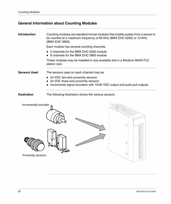
Introduction Counting modules are standard format modules that enable pulses from a sensor to be counted at a maximum frequency of 60 KHz (BMX EHC 0200) or 10 KHz (BMX EHC 0800).
Each module has several counting channels:
2 channels for the BMX EHC 0200 module8 channels for the BMX EHC 0800 module
These modules may be installed in any available slot in a Modicon M340 PLC station rack.
Sensors Used The sensors used on each channel may be:
24 VDC two-wire proximity sensors 24 VDC three-wire proximity sensorsIncremental signal encoders with 10/30 VDC output and push-pull outputs.
Illustration The following illustration shows the various sensors.
Proximity sensors
Incremental encoder
18 35013355.02 07/2008
Counting Modules
Physical Description of the Counting Modules
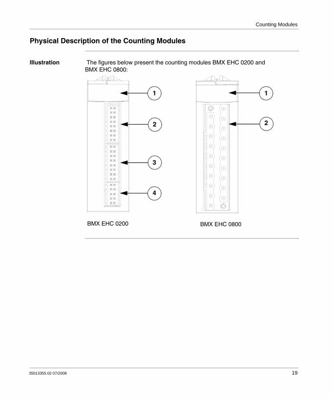
Illustration The figures below present the counting modules BMX EHC 0200 and BMX EHC 0800:
BMX EHC 0200 BMX EHC 0800
1
2
3
4
1
22
35013355.02 07/2008 19

Counting Modules
Physical Elements of the Modules
The table below presents the elements of the counting modules:
Accessories The BMX EHC 0200 module requires the use of the following accessories:
Two 16-pin terminal blocksOne 10-pin terminal blockOne BMX XSP 0400/0600/0800/1200 electromagnetic compatibility kit (see Modicon M340 Using Unity Pro Processors, Racks, and Power Supply Modules Setup Manual, BMX XSP xxxx Protection Bar)
The BMX EHC 0800 module requires the use of a BMX FTB 2000/2010/2020 terminal block and a BMX XSP 0400/0600/0800/1200 electromagnetic compatibility kit (see Modicon M340 Using Unity Pro Processors, Racks, and Power Supply Modules Setup Manual, BMX XSP xxxx Protection Bar).
Module Number Description
BMX EHC 0200 1 Module state LEDs:State LEDs at module levelState LEDs at channel level
2 16-pin connector to connect the counter 0 sensors
3 16-pin connector to connect the counter 1 sensors
4 10-pin connector to connect:Auxiliary outputsSensor power supplies
BMX EHC 0800 1 Module state LEDs:State LEDs at module levelState LEDs at channel level
2 20-pin connector compatible with discrete inputs/outputs
Note: The two 16-pin connectors and the 10-pin connector are available under the reference BMX XTS HSC 20.
20 35013355.02 07/2008
35013355.02 07/2008
3
Presentation of the Counting Modules OperationAt a Glance
Subject of this Section
This section deals with the operation of the counting modules.
What's in this Chapter?
This chapter contains the following topics:
Topic Page
General Information about the Counting Modules Operation 22
Presentation of the BMX EHC 0200 Counting Module 23
Overview of BMX EHC 0200 Module Functionalities 25
Presentation of the BMX EHC 0800 Counting Module 27
Overview of BMX EHC 0800 Module Functionalities 29
21

Counting Modules
General Information about the Counting Modules Operation
Introduction The BMX EHC 0200 and BMX EHC 0800 modules are counting modules from the Modicon M340 modular PLC range. They support all Unity Pro software functionalities.
These modules have:
Counting-related functions (comparison, capture, homing, reset to 0) Event generation functions designed for the application programOutputs for actuator use (contacts, alarms, relays)
Characteristics The main characteristics of these modules are as follows.
Type Application Number of channels per module
Number of physical inputs per channel
Number of physical outputs per channel
Maximum frequency
BMX EHC 0200 CountingDowncountingMeasurementFrequency meterFrequency generatorAxis monitoring
2 6 2 60 KHz
BMX EHC 0800 CountingDowncountingFrequency meterEncoder interface
8 2 in single mode3 in special dual phase mode
0 10 KHz
22 35013355.02 07/2008
Counting Modules
Presentation of the BMX EHC 0200 Counting Module
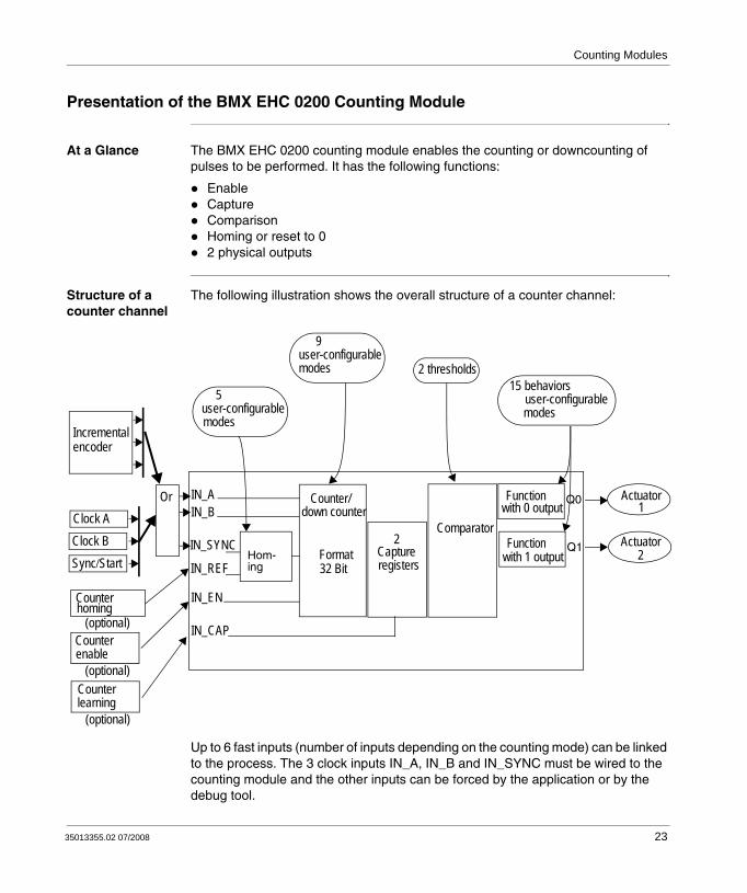
At a Glance The BMX EHC 0200 counting module enables the counting or downcounting of pulses to be performed. It has the following functions:
EnableCaptureComparisonHoming or reset to 02 physical outputs
Structure of a counter channel
The following illustration shows the overall structure of a counter channel:
Up to 6 fast inputs (number of inputs depending on the counting mode) can be linked to the process. The 3 clock inputs IN_A, IN_B and IN_SYNC must be wired to the counting module and the other inputs can be forced by the application or by the debug tool.
Function Q0
Comparator2
Capture
IN_EN
IN_AIN_B
IN_CAP
Counter/down counter
32 BitHom-
IN_SYNC
IN_REF
Actuator1
Actuator2
Clock AClock BSync/Start
Incrementalencoder
Counterenable
(optional)Counterlearning
(optional)
5 user-configurablemodes
9 user-configurablemodes 2 thresholds
15 behaviorsuser-configurablemodes
Counterhoming
with 0 output
Function Q1with 1 output
(optional)
ingFormat
registers
Or
35013355.02 07/2008 23

Counting Modules
The capture0 capture register is used to record the counter value before homing or reseting. The capture1 capture register is used to learn the counter value at any time.
The 2 hard compare blocks act mainly to boost the reflex action on outputs Q0 and Q1. Delay is basically about 500 s. However, 1 output function (over 15) per block is hardwired. With that function, delay becomes less than 200 s without deviation in repetition.
24 35013355.02 07/2008

Counting Modules
Overview of BMX EHC 0200 Module Functionalities
At a Glance This part presents the different types of user applications for the BMX EHC 0200 module.
Measurement The following table presents the measurement functionality for the BMX EHC 0200 module:
Counting The following table presents the counting functionality for the BMX EHC 0200 module:
Frequency Generator
The following table presents the frequency generator functionality for the BMX EHC 0200 module:
User application type Mode
Speed measurement/stream measurement Frequency
Random events monitoring Event counting
Pulse evaluation/Speed control Period measuring
Flow control Ratio
User application type Mode
Grouping One shot counter
Level 1 packaging/labeling Modulo loop counter
Level 2 packaging/labeling Free large counter
Accumulator Free large counter
Axis control Free large counter
Note: In case of a user application such as level 1 packaging/labeling, the machine makes constant spacing between parts. In case of a user application such as level 2 packaging/labeling, the counting module learns the incoming edge of each part.
User application type Mode
Input frequency device Pulse width modulation
35013355.02 07/2008 25
Counting Modules
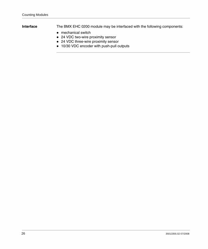
Interface The BMX EHC 0200 module may be interfaced with the following components:
mechanical switch24 VDC two-wire proximity sensor24 VDC three-wire proximity sensor10/30 VDC encoder with push-pull outputs
26 35013355.02 07/2008

Counting Modules
Presentation of the BMX EHC 0800 Counting Module
At a Glance The BMX EHC 0800 counting module enables the counting or downcounting of pulses to be performed. It has the following functions:
EnableCaptureComparisonLoad to preset value or reset to 0
16 bits structure The following illustration shows the 16 bits structure of a counter channel:
The diagram above is applicable for the following 5 counting modes:
Frequency modeEvent counting modeOne shot counter modeModulo loop counter mode
Comparator
1
registercapture
IN_A
IN_AUX
Counter
Format16 bits
Main clock input
5 user-configurablemodes 1 threshold
Multi-function input
Start and Preset
Reset and record
Trigger in
Direction drive
or
or
or
35013355.02 07/2008 27

Counting Modules
Up and down counter mode
32 bits structure The following illustration shows the 32 bits structure using 2 channels:
The illustration shown above is only applicable for the dual-phase counter mode.
In this mode, with the counting module it is possible to merge 2 single channels into 1 dual-phase channel. As such, it is possible to build up to 4 encoder interfaces.
ComparatorIN_AIN_B
IN_AUX
Counter
Format32 bits
Reset and record (Z)
Dual phase mode1 threshold
Dual clock inputs (A/B)
1
registercaptureIncremental encoder
28 35013355.02 07/2008
Counting Modules
Overview of BMX EHC 0800 Module Functionalities
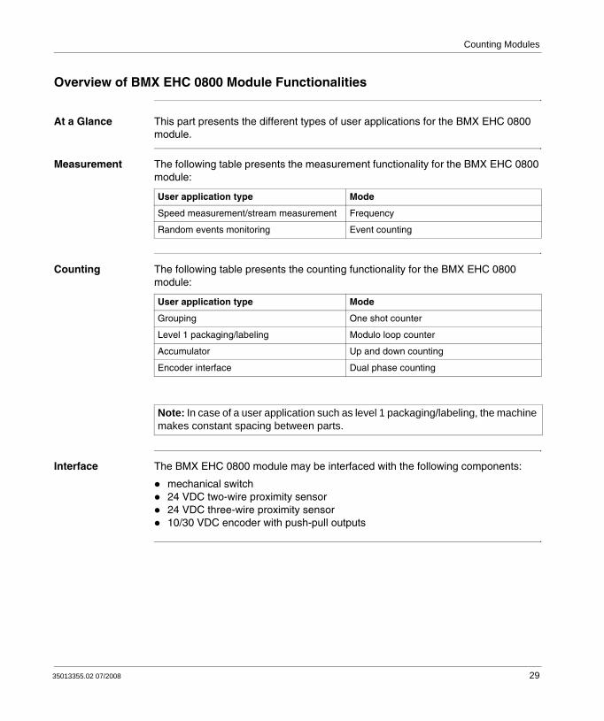
At a Glance This part presents the different types of user applications for the BMX EHC 0800 module.
Measurement The following table presents the measurement functionality for the BMX EHC 0800 module:
Counting The following table presents the counting functionality for the BMX EHC 0800 module:
Interface The BMX EHC 0800 module may be interfaced with the following components:
mechanical switch24 VDC two-wire proximity sensor24 VDC three-wire proximity sensor10/30 VDC encoder with push-pull outputs
User application type Mode
Speed measurement/stream measurement Frequency
Random events monitoring Event counting
User application type Mode
Grouping One shot counter
Level 1 packaging/labeling Modulo loop counter
Accumulator Up and down counting
Encoder interface Dual phase counting
Note: In case of a user application such as level 1 packaging/labeling, the machine makes constant spacing between parts.
35013355.02 07/2008 29

Counting Modules
30 35013355.02 07/2008

35013355.02 07/2008
II
Counting Modules Hardware ImplementationAt a Glance
Subject of this Section
This section presents the hardware implementation of the BMX EHC 0200/0800 counting modules.
What's in this Part?
This part contains the following chapters:
Chapter Chapter Name Page
4 General Rules for Installing Counting Modules 33
5 BMX EHC 0200 Counting Module Hardware Implementation 47
6 BMX EHC 0800 Counting Module Hardware implementation 61
31

Counting Modules Hardware Implementation
32 35013355.02 07/2008

35013355.02 07/2008
4
General Rules for Installing Counting ModulesAt a Glance
Subject of this Chapter
This chapter presents the general rules for installing counting modules.
What's in this Chapter?
This chapter contains the following topics:
Topic Page
Fitting of Counting Modules 34
Fitting 10-Pin and 16-Pin Terminal Blocks to a BMX EHC 0200 Counting Module
37
How to Connect BMX EHC 0200 Module: Connecting 16-Pin and 10-Pin Terminal Blocks
38
Fitting a 20-Pin Terminal Block to a BMX EHC 0800 Counting Module 39
How to Connect BMX EHC 0800 Module: Connecting a 20-Pin Terminal Block 43
33
Counting Modules: General Rules for Installation
Fitting of Counting Modules
At a Glance The counting modules are powered by the rack bus. The modules may be handled without turning off power supply to the rack, without causing any danger and without there being any risk of damage or disturbance to the PLC.
Fitting operations (installation, assembly and disassembly) are described below.
Installation Precautions
The counting modules may be installed in any of the positions in the rack except for the first two (marked PS and 00) which are reserved for the rack’s power supply module (BMX CPS ••••) and the processor (BMX P34 ••••) respectively. Power is supplied by the bus at the bottom of the rack (3.3 V and 24 V).
Before installing a module, you must take off the protective cap from the module connector located on the rack.
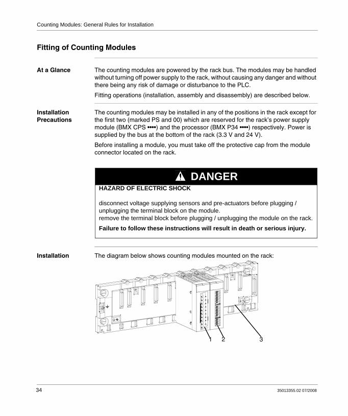
Installation The diagram below shows counting modules mounted on the rack:
HAZARD OF ELECTRIC SHOCK disconnect voltage supplying sensors and pre-actuators before plugging / unplugging the terminal block on the module. remove the terminal block before plugging / unplugging the module on the rack.
Failure to follow these instructions will result in death or serious injury.
DANGER
1 2 3
34 35013355.02 07/2008
Counting Modules: General Rules for Installation
The following table describes the different elements which make up the assembly below:
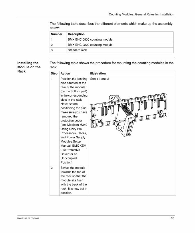
Installing the Module on the Rack
The following table shows the procedure for mounting the counting modules in the rack:
Number Description
1 BMX EHC 0800 counting module
2 BMX EHC 0200 counting module
3 Standard rack
Step Action Illustration
1 Position the locating pins situated at the rear of the module (on the bottom part) in the corresponding slots in the rack.Note: Before positioning the pins, make sure you have removed the protective cover (see Modicon M340 Using Unity Pro Processors, Racks, and Power Supply Modules Setup Manual, BMX XEM 010 Protective Cover for an Unoccupied Position).
Steps 1 and 2
2 Swivel the module towards the top of the rack so that the module sits flush with the back of the rack. It is now set in position.
1
2
35013355.02 07/2008 35

Counting Modules: General Rules for Installation
3 Tighten the safety screw to ensure that the module is held in place on the rack.Tightening torque: Max. 1.5 N.m
Step 3
Step Action Illustration
3
36 35013355.02 07/2008
Counting Modules: General Rules for Installation
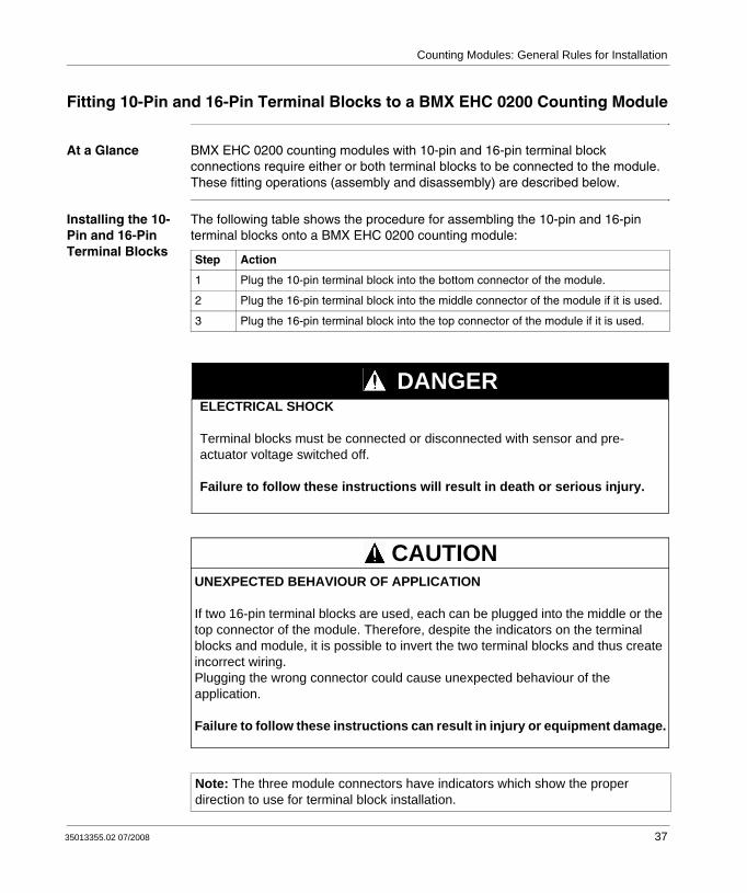
Fitting 10-Pin and 16-Pin Terminal Blocks to a BMX EHC 0200 Counting Module
At a Glance BMX EHC 0200 counting modules with 10-pin and 16-pin terminal block connections require either or both terminal blocks to be connected to the module. These fitting operations (assembly and disassembly) are described below.
Installing the 10-Pin and 16-Pin Terminal Blocks
The following table shows the procedure for assembling the 10-pin and 16-pin terminal blocks onto a BMX EHC 0200 counting module:
Step Action
1 Plug the 10-pin terminal block into the bottom connector of the module.
2 Plug the 16-pin terminal block into the middle connector of the module if it is used.
3 Plug the 16-pin terminal block into the top connector of the module if it is used.
Note: The three module connectors have indicators which show the proper direction to use for terminal block installation.
ELECTRICAL SHOCK
Terminal blocks must be connected or disconnected with sensor and pre-actuator voltage switched off.
Failure to follow these instructions will result in death or serious injury.
DANGER
UNEXPECTED BEHAVIOUR OF APPLICATION
If two 16-pin terminal blocks are used, each can be plugged into the middle or the top connector of the module. Therefore, despite the indicators on the terminal blocks and module, it is possible to invert the two terminal blocks and thus create incorrect wiring.Plugging the wrong connector could cause unexpected behaviour of the application.
Failure to follow these instructions can result in injury or equipment damage.
CAUTION
35013355.02 07/2008 37

Counting Modules: General Rules for Installation
How to Connect BMX EHC 0200 Module: Connecting 16-Pin and 10-Pin Terminal Blocks
At a Glance The BMX EHC 0200 counting module uses the following terminal blocks:
Two 16-pin terminal blocks for the inputsOne 10-pin terminal block for supplies at the module output and outputs
Cable Ends and Contacts
Each terminal block can accommodate:Solid bare wiresFlexible bare wires
Description of the 20-Pin Terminal Blocks
The table below shows the characteristics of the BMX EHC 0200 terminal blocks:
Characteristic Available
Type of terminal block Spring terminal blocks
Number of wires accommodated 1
Number of wire gauges accommodated
minimum AWG 24 (0.5 mm2)
maximum AWG 17 (1 mm2)
Wiring constraints To insert and remove wires from the connectors, use a 2.5 x 0.4 mm screwdriver to open the round receptacle by pushing on the corresponding plate (numbers 1 to 16 for the 16-pin connector and numbers 1 to 10 for the 10-pin connector). Push the flexible plate down on the outside (the side closest to the corresponding receptacle).A screwing (rotating) or bending motion is not required.
ELECTRICAL SHOCK
Terminal blocks must be connected or disconnected with sensor and pre-actuator voltage switched off.
Failure to follow these instructions will result in death or serious injury.
DANGER
38 35013355.02 07/2008

Counting Modules: General Rules for Installation
Fitting a 20-Pin Terminal Block to a BMX EHC 0800 Counting Module
At a Glance BMX EHC 0800 counting modules with 20-pin terminal block connections require the latter to be connected to the module. These fitting operations (assembly and disassembly) are described below.
Installing the 20-Pin Terminal Block
The following table shows the procedure for assembling the 20-pin terminal block onto a BMX EHC 0800 counting module:
Assembly procedure:
Step Action
1 Once the module is in place on the rack, install the terminal block by inserting the terminal block encoder (the rear lower part of the terminal) into the module's encoder (the front lower part of the module), as shown above.
2 Fix the terminal block to the module by tightening the 2 mounting screws located on the lower and upper parts of the terminal block.Tightening torque: 0.4 N.m.
Note: If the screws are not tightened, there is a risk that the terminal block will not be properly fixed to the module.
1
2
35013355.02 07/2008 39

Counting Modules: General Rules for Installation
Coding the20-Pin Terminal Block
When a 20-pin terminal block is installed on a module dedicated to this type of terminal block, you can code the terminal block and the module using studs. The purpose of the studs is to prevent the terminal block from being mounted on another module. Handling errors can then be avoided when replacing a module.
Coding is done by the user with the STB XMP 7800 guidance wheel’s studs. You can only fill the 6 slots in the middle of the left side (as seen from the wiring side) of the terminal block, and can fill the module’s 6 guidance slots on the left side.
To fit the terminal block to the module, a module slot with a stud must correspond to an empty slot in the terminal block, or a terminal block with a stud must correspond to an empty slot in the module. You can fill up to and including either of the 6 available slots as desired.
The diagram below shows a guidance wheel as well as the slots on the module used for coding the 20-pin terminal blocks:
Guidance wheel
Detachable stud
Guidance slots
Module slots
40 35013355.02 07/2008

Counting Modules: General Rules for Installation
The diagram below shows an example of a coding configuration that makes it possible to fit the terminal block to the module:
The diagram below shows an example of coding configuration with which it is not possible to fit the terminal block to the module:
ModuleTerminal block
Slots filled with studs
Empty slotsSlots filled with studs
Empty slots
ModuleTerminal block
Slots filled with studs
Empty slotsSlots filled with studs
Empty slot
35013355.02 07/2008 41

Counting Modules: General Rules for Installation
Note: The module connector have indicators which show the proper direction to use for terminal block installation.
ELECTRICAL SHOCK
Terminal blocks must be connected or disconnected with sensor and pre-actuator voltage switched off.
Failure to follow these instructions will result in death or serious injury.
DANGER
DESTRUCTION OF THE MODULE
Code the terminal block as described above to prevent the terminal block from being mounted on another module.Plugging the wrong connector could cause the module to be destroyed.
Failure to follow these instructions can result in injury or equipment damage.
CAUTION
UNEXPECTED BEHAVIOUR OF APPLICATION
Code the terminal block as described above to prevent the terminal block from being mounted on another module.Plugging the wrong connector could cause unexpected behaviour of the application.
Failure to follow these instructions can result in injury or equipment damage.
CAUTION
42 35013355.02 07/2008

Counting Modules: General Rules for Installation
How to Connect BMX EHC 0800 Module: Connecting a 20-Pin Terminal Block
At a Glance There are 3 types of 20-pin terminal blocks:
BMX FTB 2010 screw clamp terminal blocks,BMX FTB 2000 caged terminal blocks,BMX FTB 2020 spring terminal blocks.
Cable Ends and Contacts
Each terminal block can accommodate:
Bare wires
Wires with DZ5-CE type cable ends:
Description of the 20-Pin Terminal Blocks
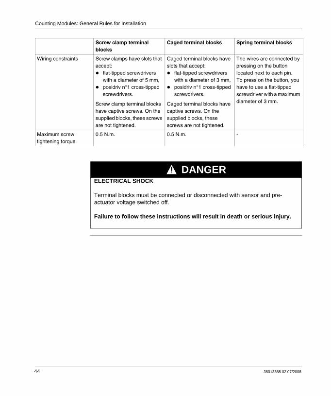
The table below shows the description of the 3 types of 20-pin terminal blocks:
Screw clamp terminal blocks
Caged terminal blocks Spring terminal blocks
Illustration
Number of wires accommodated
2 1 1
Number of wire gauges accommodated
minimum AWG 24 (0.34 mm2)
maximum AWG 16 (1.5 mm2)
35013355.02 07/2008 43
Counting Modules: General Rules for Installation
Wiring constraints Screw clamps have slots that accept:
flat-tipped screwdrivers with a diameter of 5 mm,posidriv n°1 cross-tipped screwdrivers.
Screw clamp terminal blocks have captive screws. On the supplied blocks, these screws are not tightened.
Caged terminal blocks have slots that accept:
flat-tipped screwdrivers with a diameter of 3 mm,posidriv n°1 cross-tipped screwdrivers.
Caged terminal blocks have captive screws. On the supplied blocks, these screws are not tightened.
The wires are connected by pressing on the button located next to each pin.To press on the button, you have to use a flat-tipped screwdriver with a maximum diameter of 3 mm.
Maximum screw tightening torque
0.5 N.m. 0.5 N.m. -
Screw clamp terminal blocks
Caged terminal blocks Spring terminal blocks
ELECTRICAL SHOCK
Terminal blocks must be connected or disconnected with sensor and pre-actuator voltage switched off.
Failure to follow these instructions will result in death or serious injury.
DANGER
44 35013355.02 07/2008
Counting Modules: General Rules for Installation
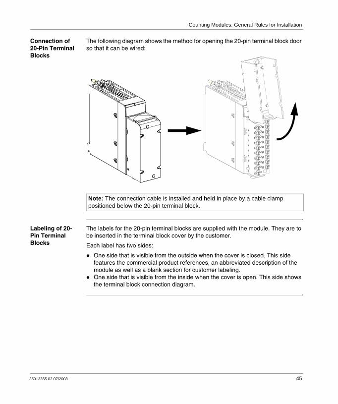
Connection of 20-Pin Terminal Blocks
The following diagram shows the method for opening the 20-pin terminal block door so that it can be wired:
Labeling of 20-Pin Terminal Blocks
The labels for the 20-pin terminal blocks are supplied with the module. They are to be inserted in the terminal block cover by the customer.
Each label has two sides:
One side that is visible from the outside when the cover is closed. This side features the commercial product references, an abbreviated description of the module as well as a blank section for customer labeling.One side that is visible from the inside when the cover is open. This side shows the terminal block connection diagram.
Note: The connection cable is installed and held in place by a cable clamp positioned below the 20-pin terminal block.
35013355.02 07/2008 45

Counting Modules: General Rules for Installation
46 35013355.02 07/2008

35013355.02 07/2008
5
BMX EHC 0200 Counting Module Hardware ImplementationAt a Glance
Subject of this Section
This section deals with the hardware characteristics of the BMX EHC 0200 module.
What's in this Chapter?
This chapter contains the following sections:
Section Topic Page
5.1 Characteristics and Diagnostics of the BMX EHC 0200 Module 48
47
BMX EHC 0200
5.1 Characteristics and Diagnostics of the BMX EHC 0200 Module
At a Glance
Subject of this Section
This section deals with the general characteristics and diagnostics of the BMX EHC 0200 module.
What's in this Section?
This section contains the following topics:
Topic Page
Characteristics for the BMX EHC 0200 Module and its Inputs and Outputs 49
Display and Diagnostics of the BMX EHC 0200 Counting Module 51
BMX EHC 0200 Module Wiring 53
48 35013355.02 07/2008

BMX EHC 0200
Characteristics for the BMX EHC 0200 Module and its Inputs and Outputs
General Characteristics
This table presents the general characteristics for the module:
Module type 2 counting channels
Maximum frequency at counting inputs 60 kHz
Number of inputs/outputs per counting channel
Inputs Six Type 3 24 VDC inputs
Outputs Two 24 VDC outputs
Power Supply Sensor supply voltage
19.2...30 VDC
Module consumption
Does not take into account sensors or encoder consumption
All inputs OFF: Typical: 15mAAll inputs ON: Typical: 75mA
Actuator supply current
500 mA maximum per output2 A per module
Power distribution to sensors Yes with short-circuit and overload protection - typical 300 mA (short-circuit limited to 2.5 A)
Hot replacement Yes, under the following conditions: The module may be removed and reinserted into its location while the rack is switched on, but the counter may have to be revalidated when it is reinserted into its base.
Dimensions Width Module only 32 mm
On the rack 32 mm
Height Module only 103.76 mm
On the rack 103.76 mm
Depth Module only 92 mm
On the rack 104.5 mm
Encoder compliance 10...30 VDC incremental encoder model with push-pull at outputs
Insulation voltage of the ground to the bus 1500 V RMS for 1 min
Rack 24 V supply bus Current for the 24 V bus
Typical: 40 mA
Rack 3 V supply bus Current for the 3 V bus
Typical: 200 mA
Module Cycle Time 1 ms
35013355.02 07/2008 49

BMX EHC 0200
Input Characteristics
This table presents the general characteristics of the input channels for the module:
Characteristics of Outputs
This table presents the general characteristics of the output channels for the module:
Number of inputs per channel Six 24 VDC inputs
Inputs: IN A, IN B, IN SYNC, IN EN, IN REF, IN CAP
Voltage 30 VDC maximum
At state 1 Voltage 11 VDC... 30 VDC
Current 5 mA (up to 30 VDC)
At state 0 Voltage < 5 VDC
Current < 1.5 mA
Current at 11 VDC > 2 mA
Number of outputs per channel 2
Type source 24 VDC 0.5 A
Voltage 19.2...30 VCC
Minimum load current None
Maximum load current Each point 0.5 A
Per module 2 A
Leakage current at state 0 0.1 mA maximum
Voltage drop at state 1 3 VDC maximum
Output current short-circuit Each point 1.5 A maximum
Maximum load capacity 50 μF
Short-circuit and overload Channel protection
Polarity for each output channel By default Normal logic on both channels
User configuration
Reverse logic for one or several channels
Maximum inductive load The inductive load is calculated using the following formula:
The formula above uses the following parameters:
L: load inductance in HenryI: load current in AmperesF: switching frequency in Hertz
L 0.5 I2⁄ F×=
50 35013355.02 07/2008

BMX EHC 0200
Display and Diagnostics of the BMX EHC 0200 Counting Module
At a Glance The BMX EHC 0200 counting module has LEDs that enable the status of the module to be viewed:
Module state LEDs: RUN, ERR, I/OState LEDs for inputs/outputs of each channel: IA, IB, IS, IE, IP, IC, Q0 and Q1.
Illustration The following drawing shows the display screen of the BMX EHC 0200 module:
Fault Diagnostics
The following table presents the various module states according to the LED states:
RUN ERR I/OIA0 IB0 IS0 IE0 IP0 IC0 Q00 Q10
IA1 IB1 IS1 IE1 IP1 IC1 Q01 Q11
Module status LED indicators
ERR RUN IO IA IB IS IE IP IC Q0 Q1
The module is faulty or switched off
The module has a fault
The module is not configured
The module has lost communication
The sensors have a supply fault
The actuators have a supply fault
Short circuit on output Q0
Short circuit on output Q1
The channels are operational
The voltage is present at output Q0
The voltage is present at output Q1
The voltage is present at input IN_A
The voltage is present at input IN_B
35013355.02 07/2008 51

BMX EHC 0200
The voltage is present at input IN_SYNC
The voltage is present at input IN_EN
The voltage is present at input IN_REF
The voltage is present at input IN_CAP
Legend
LED on
LED off
LED flashing slowly
LED flashing fast
An empty cell indicates that the state of the LED(s) is not taken into account
52 35013355.02 07/2008

BMX EHC 0200
BMX EHC 0200 Module Wiring
At a Glance The BMX EHC 0200 counting module uses the following:Two 16-pin connectors for the inputsOne 10-pin connector for supplies at the module output and outputs
Field sensors The module has type 3 of CEI 1131 inputs that support signals from mechanical switching equipment such as:
Contact relaysPush-buttonsLimit switch sensorsSwitches with 2 or 3 wires
The equipment must have the following characteristics:
Voltage drop less than 8 VMinimum operating current less than or equal to 2 mAMaximum current in blocked state less than or equal to 1.5 mA
The module complies with most encoders that have a supply of between 10 and 30 V and push-pull outputs.
Note: The two 16-pin connectors and the 10-pin connector are sold separately and are available in the BMX XTS HSC 20 connection kit.
HAZARD OF ELECTRIC SHOCK
disconnect voltage supplying sensors and pre-actuators before plugging / unplugging the terminal block on the module.
remove the terminal block before plugging / unplugging the module on the rack.
Failure to follow these instructions will result in death or serious injury.
DANGER
Note: The module’s 24 V supply for sensors has thermal and short-circuit protection.
35013355.02 07/2008 53
BMX EHC 0200
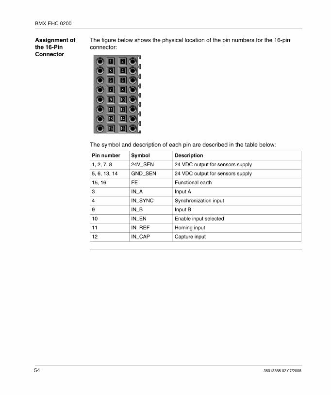
Assignment of the 16-Pin Connector
The figure below shows the physical location of the pin numbers for the 16-pin connector:
The symbol and description of each pin are described in the table below:
Pin number Symbol Description
1, 2, 7, 8 24V_SEN 24 VDC output for sensors supply
5, 6, 13, 14 GND_SEN 24 VDC output for sensors supply
15, 16 FE Functional earth
3 IN_A Input A
4 IN_SYNC Synchronization input
9 IN_B Input B
10 IN_EN Enable input selected
11 IN_REF Homing input
12 IN_CAP Capture input
1
3
5
7
9
11
13
15
2
4
6
8
10
12
14
16
54 35013355.02 07/2008

BMX EHC 0200
Sensor Connections
The example below shows sensors with applied to inputs IN_A and IN_B and equipment with applied to inputs IN_EN and IN_SYNC:
1 IN_A input2 IN_B input3 IN_SYNC input (synchronization input)4 IN_EN input (enable input)
Encoder Connection
The example below shows an incremental encoder used for axis control and the three auxiliary inputs used especially for the 32-bit counter mode:
1 Encoder (inputs A, B and Z)2 IN_REF input (homing input)3 IN_EN input (enable input)4 IN_CAP input (capture input)
1
3
5
7
9
11
13
15
2
4
6
8
10
12
14
16
+
+
-
-
2
1 4
3
3
4
2
GND
1
BAZ
10/30V
Encoder
1
3
5
7
9
11
13
15
2
4
6
8
10
12
14
16
35013355.02 07/2008 55
BMX EHC 0200
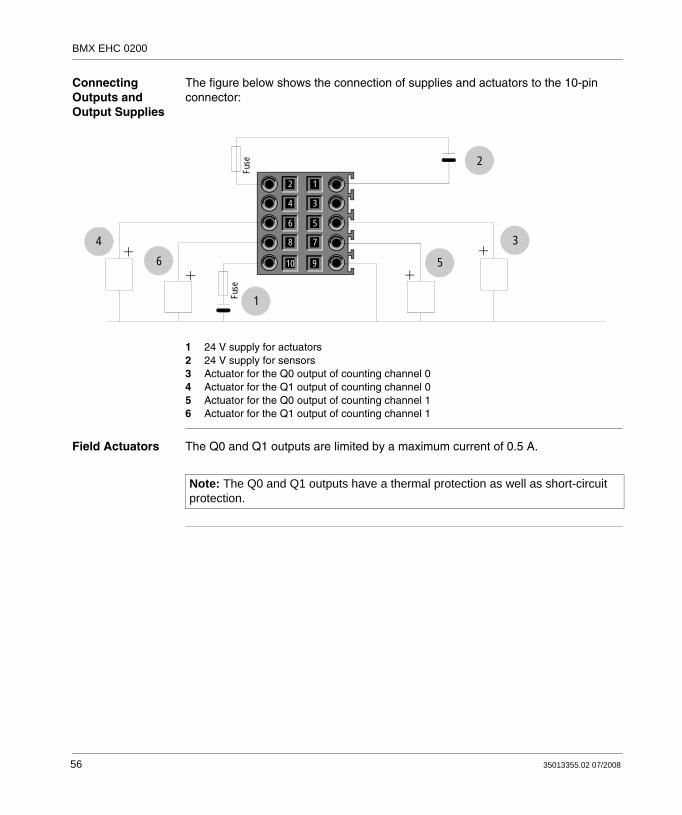
Connecting Outputs and Output Supplies
The figure below shows the connection of supplies and actuators to the 10-pin connector:
1 24 V supply for actuators2 24 V supply for sensors3 Actuator for the Q0 output of counting channel 04 Actuator for the Q1 output of counting channel 05 Actuator for the Q0 output of counting channel 16 Actuator for the Q1 output of counting channel 1
Field Actuators The Q0 and Q1 outputs are limited by a maximum current of 0.5 A.
3
5
1
64
2
1
3
5
7
9
2
4
6
8
10
Fuse
Fuse
Note: The Q0 and Q1 outputs have a thermal protection as well as short-circuit protection.
56 35013355.02 07/2008

BMX EHC 0200
Assignment of the 10-Pin Connector
The figure below shows the physical location of the pin numbers for the 10-pin connector:
The symbol and description of each pin are described in the table below:
Pin number Symbol Description
1 24V_IN 24 VDC input for sensors supply
2 GND_IN 24 VDC input for sensors supply
5 Q0-1 Q1 output for counting channel 0
6 Q0-0 Q0 output for counting channel 0
7 Q1-1 Q1 output for counting channel 1
8 Q1-0 Q0 output for counting channel 1
9 24V_OUT 24 VDC input for actuators supply
10 GND_OUT 24 VDC input for actuators supply
1
3
5
7
9
2
4
6
8
10
35013355.02 07/2008 57

BMX EHC 0200
Safety Instructions
UNEXPECTED EQUIPMENT OPERATION
Follow those instructions to reduce electromagnetic perturbations:adapt the programmable filtering to the frequency applied at the inputs, oruse a shielded cable (connected to the functional ground) connected to pins 15 and 16 of the connector when using an encoder or a fast detector.
In a highly disturbed environment,use the BMX XSP 0400/0600/0800/1200 electromagnetic protection kit (see Modicon M340 Using Unity Pro Processors, Racks, and Power Supply Modules Setup Manual, BMX XSP xxxx Protection Bar) (See Modicon M340 using Unity Pro, Processors, Racks and Power Supply Modules, BMX XSP xxx Protection Bar) to connect the shielding without programmable filtering anduse a specific 24 VDC supply for inputs and a shielded cable for connecting the supply to the module.
Electromagnetic perturbations may cause the application to operate in an unexpected manner.
Failure to follow these instructions can result in death, serious injury, or equipment damage.
WARNING
58 35013355.02 07/2008

BMX EHC 0200
The figure below shows the recommended circuit for high-noise environment using the BMX XSP 0400/0600/0800/1200 electromagnetic protection kit:
BMX EHC 0200 counting module
BMX XSP •••• kit
Encoder
24 VDC fast sensorspower supply
IMPROPER FUSE SELECTION
Use fast acting fuses to protect the electronic components of the module from overcurrent and reverse polarity of the input/output supplies. Improper fuse selection could result to damage to the module.
Failure to follow these instructions can result in injury or equipment damage.
CAUTION
35013355.02 07/2008 59

BMX EHC 0200
60 35013355.02 07/2008

35013355.02 07/2008
6
BMX EHC 0800 Counting Module Hardware implementationAt a Glance
Subject of this Section
This section deals with the harware characteristics of the BMX EHC 0800 module.
What's in this Chapter?
This chapter contains the following sections:
Section Topic Page
6.1 Characteristics and Diagnostics of the BMX EHC 0800 Module 62
61

BMX EHC 0800
6.1 Characteristics and Diagnostics of the BMX EHC 0800 Module
At a Glance
Subject of this Section
This section deals with the general characteristics and diagnostics of the BMX EHC 0800 module.
What's in this Section?
This section contains the following topics:
Topic Page
Characteristics of the BMX EHC 0800 Module and its Inputs 63
Display and Diagnostics of the BMX EHC 0800 Counting Module 65
BMX EHC 0800 Module Wiring 68
62 35013355.02 07/2008
BMX EHC 0800
Characteristics of the BMX EHC 0800 Module and its Inputs
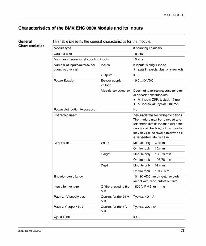
General Characteristics
This table presents the general characteristics for the module:
Module type 8 counting channels
Counter size 16 bits
Maximum frequency at counting inputs 10 kHz
Number of inputs/outputs per counting channel
Inputs 2 inputs in single mode3 inputs in special dual phase mode
Outputs 0
Power Supply Sensor supply voltage
19.2...30 VDC
Module consumption Does not take into account sensors or encoder consumption
All inputs OFF: typical: 15 mAAll inputs ON: typical: 80 mA
Power distribution to sensors No
Hot replacement Yes, under the following conditions: The module may be removed and reinserted into its location while the rack is switched on, but the counter may have to be revalidated when it is reinserted into its base.
Dimensions Width Module only 32 mm
On the rack 32 mm
Height Module only 103.76 mm
On the rack 103.76 mm
Depth Module only 92 mm
On the rack 104.5 mm
Encoder compliance 10...30 VDC incremental encoder model with push-pull at outputs
Insulation voltage Of the ground to the bus
1500 V RMS for 1 min
Rack 24 V supply bus Current for the 24 V bus
Typical: 40 mA
Rack 3 V supply bus Current for the 3 V bus
Typical: 200 mA
Cycle Time 5 ms
35013355.02 07/2008 63

BMX EHC 0800
Input Characteristics
This table presents the general characteristics of the input channels for the module:
Number of inputs per channel Two 24 VDC inputs
Inputs: IN_A, IN_AUX Voltage 30 VDC
At state 1 Voltage 11 VDC...30 VDC
Current 4.5 mA (up to 30 VDC)
At state 0 Voltage < 5 VDC
Current < 1.5 mA
Current at 11 VDC > 2 mA
64 35013355.02 07/2008

BMX EHC 0800
Display and Diagnostics of the BMX EHC 0800 Counting Module
At a Glance The BMX EHC 0800 counting module has LEDs that enable the following to be viewed:
the status of the module: RUN, ERR, I/Othe input status of every channel
Illustration The following drawing shows the display screen of the BMX EHC 0800 module:
RUN ERR I/O
Clock Inputs C0 C1 C2 C3 C4 C5 C6 C7
Aux Inputs Ax0 Ax1 Ax2 Ax3 Ax4 Ax5 Ax6 Ax7
35013355.02 07/2008 65

BMX EHC 0800
Fault Diagnostics
The following table enables the diagnostics of faults according to the various LEDs.
Module status LED indicators
RUN ERR I/O C0 C1 C2 C3 C4 C5 C6 C7
The module is faulty or switched off
The module has a fault
The module is not configured
The module has lost communication
The sensors have a supply fault
The channels are operational
The voltage is present at input IN_A of counter 0
The voltage is present at input IN_A of counter 1
The voltage is present at input IN_A of counter 2
The voltage is present at input IN_A of counter 3
The voltage is present at input IN_A of counter 4
The voltage is present at input IN_A of counter 5
The voltage is present at input IN_A of counter 6
The voltage is present at input IN_A of counter 7
Module status LED indicators
RUN ERR I/O A0 A1 A2 A3 A4 A5 A6 A7
66 35013355.02 07/2008

BMX EHC 0800
The channels are operational
The voltage is present at input IN_AUX of counter 0
The voltage is present at input IN_AUX of counter 1
The voltage is present at input IN_AUX of counter 2
The voltage is present at input IN_AUX of counter 3
The voltage is present at input IN_AUX of counter 4
The voltage is present at input IN_AUX of counter 5
The voltage is present at input IN_AUX of counter 6
The voltage is present at input IN_AUX of counter 7
Legend
LED on
LED off
LED flashing slowly
LED flashing fast
An empty cell indicates that the state of the LED(s) is not taken into account
35013355.02 07/2008 67

BMX EHC 0800
BMX EHC 0800 Module Wiring
At a Glance The BMX EHC 0800 counting module uses a standard BMX FTB 2000/2010/2020 20-pin connector (wiring terminal) .
Field Sensors The module has type 3 inputs that support signals from mechanical switching equipment such as contact relays, push-buttons, limit switch sensors and two or three-wire switches that have:
a voltage drop of less than 8V,current when ON more than or equal to 2 mA,current when OFF up to 1.5 mA.
The module complies with all encoders that have a supply of between 10 and 30 VDC and push-pull outputs. Shielding is required if there is no filtering.
HAZARD OF ELECTRIC SHOCK
disconnect voltage supplying sensors and pre-actuators before plugging / unplugging the terminal block on the module.
remove the terminal block before plugging / unplugging the module on the rack.
Failure to follow these instructions will result in death or serious injury.
DANGER
68 35013355.02 07/2008

BMX EHC 0800
Pin Assignments The following table describes the assignment of the 20-pin wiring terminal:
Sensor Connection Example
The example below shows the most complete application using sensors:
IN_A input for channel 0 2 1 IN_AUX input for channel 0
IN_A input for channel 1 or IN_B input for channel 0
4 3 IN_AUX input for channel 1
IN_A input for channel 2 6 5 IN_AUX input for channel 2
IN_A input for channel 3 or IN_B input for channel 2
8 7 IN_AUX input for channel 3
IN_A input for channel 4 10 9 IN_AUX input for channel 4
IN_A input for channel 5 or in_B input for channel 4
12 11 IN_AUX input for channel 5
IN_A input for channel 6 14 13 IN_AUX input for channel 6
IN_A input for channel 7 or IN_B input for channel 6
16 15 IN_AUX input for channel 7
VDC + power supply for sensors 18 17 Return + 24 V power supply for sensors
Functional earth, for shield continuation
20 19 Functional earth, for shield continuation
Counting channel 0
Fuse24 VDC
12
18
20
17
19
+-
Counting channel 1
Counting channel 2
Counting channel 3
Counting channel 4
Counting channel 5
Counting channel 6
Counting channel 7
34
56
78
9
1413
1516
1011
12
35013355.02 07/2008 69

BMX EHC 0800
Encoder Connection Example
The example below shows an incremental encoder connection used for axis control connected to the counter’s channel 6 used in dual phase counting mode:
Channels 0 to 5 are still used in single mode.
Channel 7 is no longer available.
Fuse
24 VDC
12
18
20
17
19
-
AZ
B (or dir) VDDReturn
Incremental encoder (10/30VDC)
Counting channel 0
Counting channel 1
Counting channel 2
Counting channel 3
Counting channel 4
Counting channel 5
Counting channel 6
45
67
89
1413
1516
1011
12
3
70 35013355.02 07/2008

BMX EHC 0800
Safety Instructions
UNEXPECTED EQUIPMENT OPERATION
Follow those instructions to reduce electromagnetic perturbations:adapt the programmable filtering to the frequency applied at the inputs, oruse a shielded cable (connected to the functional ground) connected to pins 15 and 16 of the connector when using an encoder or a fast detector.
In a highly disturbed environment,use the BMX XSP 0400/0600/0800/1200 electromagnetic protection kit (see Modicon M340 Using Unity Pro Processors, Racks, and Power Supply Modules Setup Manual, BMX XSP xxxx Protection Bar) (See Modicon M340 using Unity Pro, Processors, Racks and Power Supply Modules, BMX XSP xxx Protection Bar) to connect the shielding without programmable filtering anduse a specific 24 VDC supply for inputs and a shielded cable for connecting the supply to the module.
Electromagnetic perturbations may cause the application to operate in an unexpected manner.
Failure to follow these instructions can result in death, serious injury, or equipment damage.
WARNING
35013355.02 07/2008 71

BMX EHC 0800
The figure below shows the recommended circuit for a highly disturbed environment using the BMX XSP 0400/0600/0800/1200 electromagnetic protection kit:
BMX EHC 0800 counting module
BMX XSP •••• kit
Encoder24 VDC fast sensorspower supply
IMPROPER FUSE SELECTION
Use fast acting fuses to protect the electronic components of the module from overcurrent and reverse polarity of the input/output supplies. Improper fuse selection could result to damage to the module.
Failure to follow these instructions can result in injury or equipment damage.
CAUTION
72 35013355.02 07/2008

35013355.02 07/2008
III
Counting Modules FunctionalitiesAt a Glance
Subject of this Section
This section presents the functionalities of the BMX EHC 0200/0800 counting modules.
What's in this Part?
This part contains the following chapters:
Chapter Chapter Name Page
7 BMX EHC 0200 Counting Module Functionalities 75
8 BMX EHC 0800 Counting Module Functionalities 131
73

Counting Modules Functionalities
74 35013355.02 07/2008

35013355.02 07/2008
7
BMX EHC 0200 Counting Module FunctionalitiesAt a Glance
Subject of this Section
This section deals with functionalities and counting modes of the BMX EHC 0200 module.
What's in this Chapter?
This chapter contains the following sections:
Section Topic Page
7.1 BMX EHC 0200 Module Functionalities 76
7.2 BMX EHC 0200 Module Operation Modes 102
75

BMX EHC 0200 Functionalities
7.1 BMX EHC 0200 Module Functionalities
At a Glance
Subject of this Section
This section deals with the functionalities of the BMX EHC 0200 module.
What's in this Section?
This section contains the following topics:
Topic Page
Input Interface Blocks 77
Programmable Filtering 78
Comparison 79
Output Block Functions 82
Diagnostics 88
Synchronization, Homing, Enable, Reset to 0 and Capture Functions 90
Modulo Flag and Synchronization Flag 97
Sending Counting Events to the Application 99
76 35013355.02 07/2008

BMX EHC 0200 Functionalities
Input Interface Blocks
Description The BMX EHC 0200 counting module has six inputs:
3 fast inputs3 classic inputs
Fast Inputs The table below presents the module’s fast inputs.
Classic Inputs The table below presents the module’s classic inputs:
Input Use with sensors Use with an encoder
IN_A input Clock input for measurement or single upcounting
For signal A
IN_B input Second clock input for differential counting or measurement
For signal B
IN_SYNC input Main synchronization input used for starting and homing
For signal ZUsed for homing
Input Use
IN_EN input Used to authorize counter operation
IN_REF input Used for homing in advanced mode
IN_CAP input Used for register capture
35013355.02 07/2008 77

BMX EHC 0200 Functionalities
Programmable Filtering
At a Glance The BMX EHC 0200 counting module’s six inputs are compatible with the use of mechanical switches.
A programmable debounce filter with 3 levels (low, medium and high) is available at every input.
Debounce Filter Diagram
The figure below shows the debounce filter with a low filtering level:
In this mode, the system delays all transitions until the signal is stable for 450 μs.
Selecting the Filtering Level
The table below specifies the characteristics of each input for the selected level of filtering:
450 μs 450 μs
Input
Filtered signal
Filtering level Input Maximum delay
Minimum pulse
Maximum frequency
None IN_A, IN_B - 5 μs 60 KHz
IN_SYNC - 5 μs 200 Hz
IN_EN 50 μs - -
IN_CAP, IN_REF - 50 μs 200 Hz
Lowfor bounces > 2 KHz
IN_A, IN_B - 450 μs 1 KHz
IN_EN 450 μs - -
IN_SYNC, IN_CAP, IN_REF - 500 μs 200 Hz
Resourcefor bounces > 1 KHz
IN_A, IN_B - 1.25 ms 350 Hz
IN_EN 1.25 ms - -
IN_SYNC, IN_CAP, IN_REF - 1.25 ms 200 Hz
Highfor bounces > 250 Hz
IN_A, IN_B - 4.2 ms 100 Hz
IN_EN 4.2 ms - -
IN_SYNC, IN_CAP, IN_REF - 4.2 ms 100 Hz
78 35013355.02 07/2008
BMX EHC 0200 Functionalities
Comparison
At a Glance The comparison block operates automatically. This block is available in certain counting modes:
FrequencyPeriod measuringRatioOne shot counterModulo loop counterFree large counter
Comparison Thresholds
The comparison block has two thresholds:
The upper threshold: upper_th_value double word (%QDr.m.c.4)The lower threshold: lower_th_value double word (%QDr.m.c.2)
These two thresholds are defined in two output words of double word type (32-bit words).
The upper threshold value must be greater than the lower threshold value.
If the upper threshold is less than or equal to the lower threshold, the lower threshold does not change but it is ignored.
This rule takes into account the format of the counter value.
35013355.02 07/2008 79

BMX EHC 0200 Functionalities
Comparison Status Register
The result of the comparison is stored in the compare_status register (%IWr.m.c.1).
The values of the two capture registers and the current value of the counter are compared with the thresholds.
The possible results are:
Low: The value is less than the lower threshold value.Window: The value is between the upper and lower thresholds or equal to one of the two thresholds.High: The value is greater than the upper threshold.
The comparison status register (%IWr.m.c.1) consists of:
Update When the compare_enable bit (%QWr.m.c.0.5) is set to 0, the comparison status register is deleted.
The comparison with capture register values (0 or 1) is performed every time the registers are loaded.
The comparison with the counter current value is performed as follows:
Position of the status register bit
15 14 13 12 11 10 9 8 7 6 5 4 3 2 1 0
Compared element
Capture 1 Capture 0 Counter
Comparison result
High Window Low High Window Low High Window Low
Counting mode Comparison condition
Frequency Intervals of 10 ms
Period measuring At the end of the period
Ratio Intervals of 10 ms
Event counting Period intervals defined by the user
One shot counter Intervals of 1 msCounter reloadingCounter stopsThreshold crossing
Modulo loop Intervals of 1 msCounter reloading or resetting to 0Counter stopsThreshold crossing
80 35013355.02 07/2008

BMX EHC 0200 Functionalities
Modification of the Thresholds during the Operational Phase
When the compare_enable bit (%QWr.m.c.0.5) is set to 0, the comparison status register is deleted.
When the compare_suspend bit (%QWr.m.c.0.6) is set to 1, the value of the comparison status register is frozen until the bit switches back to 0.
The application may change threshold values without causing any disturbance when the compare_suspend bit (%QWr.m.c.0.6) is set to 1.
When this bit switches back to 0, the comparisons restart with new threshold values.
The following figure illustrates the actions of the compare_enable bit (%QWr.m.c.0.5) and the compare_suspend bit (%QWr.m.c.0.6):
Free large counter Intervals of 1 msCounter reloadingThreshold crossing
Pulse width modulation None
Counting mode Comparison condition
=X0
=Y0
=X1 =X2
=Y1 =Y2
According to X0, Y0 According to X1, Y1 According to X2, Y20 Maintaincompare_statusregister
upper_th_value
lower_th_value
compare_enable bit
compare_suspend bit
35013355.02 07/2008 81

BMX EHC 0200 Functionalities
Output Block Functions
Output Function Blocks
Every channel in the counting module has two programmable output blocks that operate with the comparison status register and affect the behavior of physical outputs Q0 and Q1.
There are two ways to control the output:From the application: in this case, the output corresponds to the status of the output bit from the output command bit.From the output function block: in this case, the user must enable the output block function. Then, the output corresponds to the status of the output bit from the function block.
The following figure shows the output function block Q0: output_0 bit( %Qr.m.c.0)
output_block_0_enable bit ( %Qr.m.c.2)
Reset to 0
Locking timedelay
output_0_echo bit(%Ir.m.c.0)
output_block_0 bit(%Ir.m.c.2)
Configurable between 1 and
65,535 ms
15 configurable modes
Comparison statusbits
AND
OR
82 35013355.02 07/2008
BMX EHC 0200 Functionalities
Validity and Forcing
Every output block is controlled by two bits:output_block_0_enable (%Qr.m.c.2) and output_0 (%Qr.m.c.0) for block 0output_block_1_enable (%Qr.m.c.3) and output_1 (%Qr.m.c.1) for block 1
The output_block_0(1)_enable bit enables the operation of the function block 1 to be authorized when it is set to 1. When the bit is set to 0, the block result is maintained at 0.
The output_0(1) bit is applied at the logic output Q0(1) and must be set to 0 when the function block is used. When the bit is set to 1, the output is forced to 1.
The output function block is determined by one of the 15 available functions.
In the operational modes where the block generates a pulse, the pulse width can be configured thanks to the configuration screen.
35013355.02 07/2008 83

BMX EHC 0200 Functionalities
Function Codes The table below shows the configurable functions:
Function code Behavior
0 No direct action
1 Low counter.The output is high if the counter value is less than the low threshold.
2 Counter in a windowThe output is high if the counter value is between the upper and lower thresholds or equal to one of the two thresholds.
3 High counter.The output is high if the counter value is greater than the upper threshold.
4 Pulse less than the lower threshold.The output pulse starts when the counter value decreases and crosses the lower threshold value -1.
5 Pulse greater than the lower threshold.The output pulse starts when the counter value increases and crosses the lower threshold value +1.
6 Pulse less than the upper threshold.The output pulse starts when the counter value decreases and crosses the upper threshold value -1.
7 Pulse greater than the upper threshold.The output pulse starts when the counter value increases and crosses the upper threshold value +1.
8 Counter stopped (only in one shot counter mode).The output changes to high if the counter is stopped.
9 Counter running (only in one shot counter mode).The output changes to high if the counter is running.
10 Capture 0 low value.The output is high if the capture 0 value is less than the lower threshold.
11 Capture 0 value in a window.The output is high if the capture 0 value is between the upper and lower thresholds or equal to one of the two thresholds.
12 Capture 0 high value.The output is high if the capture 0 value is greater than the upper threshold.
13 Capture1 low value.The output is high if the capture1 value is less than the lower threshold.
14 Capture1 value in a window.The output is high if the capture1 value is between the upper and lower thresholds or equal to one of the two thresholds.
84 35013355.02 07/2008
BMX EHC 0200 Functionalities
Output Performances
In general, these reflex actions act with a delay less than 0.6 ms. The repeatability is about +/- 0.3 ms.
Special boost functions:"Counter Low" (function code 1) applied to Output Block 0"Counter High" (function code 3) applied to Output Block 1 speed up timing.
Delay is less than 0.2 ms. The repeatability is about +/- 1 s.
Output Properties
The counting module BMX EHC 0200 enables output signals to be exchanged with two 24VCC field actuators.
It is possible to configure the following parameters for each output:The module response for fault recoveryThe output polarity for each counting channel (positive or negative polarity)The fallback mode and state for every module channel
These three parameters are described in the following pages.
15 Capture1 high value.The output is high if the capture1 value is greater than the upper threshold.
Note: The output 0 function block is inactive when using the counter in pulse width modulation mode.
Function code Behavior
35013355.02 07/2008 85
BMX EHC 0200 Functionalities
Fault Recovery response
Outputs Q0 and Q1 are current limited (0.5 A maximum).
A thermal shutdown protects each output.
When a short-circuit is detected on one of the output channels, the counting module enables one of the two following actions according to the configuration:
fault recovery parameter configured as latched off: The counting module latches off the output channelfault recovery parameter configured as autorecovery: The counting module latches off the output channel and automatically attempts to recover the fault and to resume operation on the channel when the fault is corrected.
In case of the fault recovery parameter is configured to latched off, if an output channel has been latched off because of short-circuit detection, the counting module recovers the fault upon the following sequence is processed:
The error has been correctedYou explicitly reset the fault: To reset the fault, the application software must:
Reset the output_block_enable bit if it is activeCommand the ouput to 0 V ( depends on the polarity).
In case of the fault recovery parameter is configured to auto recovery, an output channel that has been turned off because of fault detection starts operating again as soon as the fault is corrected. No user intervention is required to reset the channels.
Output Polarity It is possible to configure the polarity parameter for each output separately:
polarity parameter configured as polarity +: The physical output is 24 VDC when the output is at the high level (output_0_echo = 1)polarity parameter configured as polarity -: The physical output is 24 VDC when the output is at the low level (output_0_echo = 0)
By default, the two output channels are in positive polarity.
Note: A minimum delay of 10 s occurs before the fault is cleared in both latched off and auto recovery modes.
86 35013355.02 07/2008
BMX EHC 0200 Functionalities
Fallback Modes The fallback modes are the predefined states to which the output channels revert when the channel is not controlled by the processor (when communications are lost or when the processor is stopped for example).
You may configure the fallback mode of each output channel as one of the following modes:
with: With a fallback value. You may configure the fallback value to apply as 0 or 1without: Without fallback value. The output block function continues to operate according to the last received commands.
Note: By default, the fallback mode of the 2 output channels is with and the fallback value parameter is 0.
35013355.02 07/2008 87

BMX EHC 0200 Functionalities
Diagnostics
Consistency Rules for Inputs Interface
The input interface requires that the sensor power supply remains active for counting operations.
When the sensor power supply interrupts lasts 1 ms or less, the counter remains stable.
In case of power interrupt is greater than 1 ms, all counter values are disabled.
By default, the sensor supply fault makes the CH_ERROR (%Ir.m.c.ERR) global status bit at the high level and the red led IO lighted.
The configuration screen allows to unlink the sensor supply fault to the CH_ERROR bit by configuring the parameter Input Supply Fault as local instead of General IO Fault.
IODDT_VAR1 is of the type T_Unsigned_CPT_BMX or T_Signed_CPT_BMX
Consistency Rules for Outputs Interface
The output interface requires that the actuator power supply remains active for output blocks functions operations.
When the actuator supply voltage is insufficient the ouputs are held to 0 V.
By default, the actuator supply fault makes the CH_ERROR (%Ir.m.c.ERR) global status bit at the high level and the red led IO lighted.
The configuration screen allows to unlink the actuator supply fault to the CH_ERROR bit by configuring the parameter Output Supply Fault as local instead of General IO Fault.
IODDT_VAR1 is of the type T_Unsigned_CPT_BMX or T_Signed_CPT_BMX
88 35013355.02 07/2008

BMX EHC 0200 Functionalities
Explicit channel status words
The table below presents the composition of the %MWr.m.c.2 and %MWr.m.c.3 status words:
IO Data All input/output statuses are provided in the channel data bits.
The table below shows the channel data bits:
Status Word Bit position Designation
%MWr.m.c.2 0 External fault at inputs
1 External fault at outputs
4 Internal error or self-testing.
5 Configuration Fault
6 Communication Error
7 Application fault
%MWr.m.c.3 2 Sensor supply fault
3 Actuator supply fault
4 Short circuit on output Q0
5 Short circuit on output Q1
Input/Output data field Designation
%Ir.m.c.0 Logical state of output Q0
%Ir.m.c.1 Logical state of output Q1
%Ir.m.c.2 State of the output block function 0
%Ir.m.c.3 State of the output block function 1
%Ir.m.c.4 Electrical state of IN_A input
%Ir.m.c.5 Electrical state of IN_B input
%Ir.m.c.6 Electrical state of IN_SYNC input
%Ir.m.c.7 Electrical state of IN_EN input
%Ir.m.c.8 Electrical state of IN_REF input
%Ir.m.c.9 Electrical state of IN_CAP input
35013355.02 07/2008 89

BMX EHC 0200 Functionalities
Synchronization, Homing, Enable, Reset to 0 and Capture Functions
Introduction This section presents the functions used by the various counting modes of the BMX EHC 0200 module:
Synchronization functionHoming functionEnable functionReset to 0 functionCapture functions
Each function uses at least one of the following two bits:
valid_(function) bit: Setting this bit to 1 allows you to take into account the occurrence of an external event which activates the function. If this bit is set to 0, the event is not taken into account and does not activate the function. The functions_enabling word (%QWr.m.c.0) contains all the valid_(function) bits.force_(function) bit: Setting this bit to 1 allows you to activate the function irrespective of the status of the external event. All the force_(function) bits are %Qr.m.c.4...%Qr.m.c.8 language objects.
Synchronization Function
The synchronization function is used to synchronize the counter operation upon a transition applied to the IN_SYNC physical input or the force_sync bit set to 1.
This function is used in the following counting modes:
Pulse width modulation: to restart the output signal at the beginning (phase at 1)Modulo loop counter: to reset and start the counterOne shot counter: to preset and start the counterEvent counting: to restart the internal time base at the beginning
The user may configure the synchro edge parameter in the configuration screen by choosing from the following two possibilities to configure the sensitive edge that carries out the synchronization:
Rising edge of the IN_SYNC inputFalling edge of the IN_SYNC input
The following table presents the force_sync bit in bold which is an element of the %Qr.m.c.d output command word:
Language object
Standard symbol Meaning
%Qr.m.c.0 OUTPUT_0 Forces OUTPUT_0 to level 1
%Qr.m.c.1 OUTPUT_1 Forces OUTPUT_1 to level 1
%Qr.m.c.2 OUTPUT_BLOCK_0_ENABLE Implementation of output 0 function block
%Qr.m.c.3 OUTPUT_BLOCK_1_ENABLE Implementation of output 1 function block
90 35013355.02 07/2008

BMX EHC 0200 Functionalities
The following table presents the valid_sync bit in bold which is an element of the %QWr.m.c.0 function enabling word:
The following table presents the synchronization principle:
When the synchronization occurs, the application can react using :
either the SYNC_REF_FLAG input (%IWr.m.c.0.2) (see Modulo Flag and Synchronization Flag, p. 97)or the EVT_SYNC_PRESET input (%IWr.m.c.10.2) (see Sending Counting Events to the Application, p. 99).
%Qr.m.c.4 FORCE_SYNC Counting function synchronization and start
%Qr.m.c.5 FORCE_REF Set to preset counter value
%Qr.m.c.6 FORCE_ENABLE Implementation of counter
%Qr.m.c.7 FORCE_RESET Reset counter
%Qr.m.c.8 SYNC_RESET Reset SYNC_REF_FLAG
%Qr.m.c.9 MODULO_RESET Reset MODULO_FLAG
Language object
Standard symbol Meaning
%QWr.m.c.0.0 VALID_SYNC Synchronization and start authorization for the counting function via the IN_SYNC input
%QWr.m.c.0.1 VALID_REF Operation authorization for the internal preset function
%QWr.m.c.0.2 VALID_ENABLE Authorization of the counter enable via the IN_EN input
%QWr.m.c.0.3 VALID_CAPT_0 Capture authorization in the capture0 register
%QWr.m.c.0.4 VALID_CAPT_1 Capture authorization in the capture1 register
%QWr.m.c.0.5 COMPARE_ENABLE Comparators operation authorization
%QWr.m.c.0.6 COMPARE_SUSPEND Comparator frozen at its last value
Edge Status of the valid_sync (%QWr.m.c.0.0) bit
Status of the counter
Rising or falling edge on IN_SYNC (depending on the configuration)
Set to 0 Not synchronized
Rising or falling edge on IN_SYNC (depending on the configuration)
Set to 1 Synchronized
Rising edge on force_sync (%Qr.m.c.4) bit
Set to 0 or 1 Synchronized
Language object
Standard symbol Meaning
35013355.02 07/2008 91

BMX EHC 0200 Functionalities
Homing Function This homing function loads the value predefined in the adjust screen preset value (%MDr.m.c.6) into the counter when the preset condition (defined by the preset mode parameter) occurs. This preset condition takes into account the IN_SYNC and IN_REF physical inputs to define the reference point of the process.
This function is only used in the free large counter mode.
The user may change the Preset Mode parameter in the configuration screen by choosing from the following five possibilities to configure the preset condition:
Rising edge of the IN_SYNC inputRising edge of the IN_REF inputRising edge of the IN_SYNC input and high level of the IN_REF inputFirst rising edge of the IN_SYNC input and high level of the IN_REF input First rising edge of the IN_SYNC input and low level of the IN_REF input
The following table presents the force_ref bit in bold which is an element of the %Qr.m.c.d output command word:
The following table presents the valid_ref bit in bold which is an element of the %QWr.m.c.0 function enabling word:
Language object
Standard symbol Meaning
%Qr.m.c.0 OUTPUT_0 Forces OUTPUT_0 to level 1
%Qr.m.c.1 OUTPUT_1 Forces OUTPUT_1 to level 1
%Qr.m.c.2 OUTPUT_BLOCK_0_ENABLE Implementation of output 0 function block
%Qr.m.c.3 OUTPUT_BLOCK_1_ENABLE Implementation of output 1 function block
%Qr.m.c.4 FORCE_SYNC Counting function synchronization and start
%Qr.m.c.5 FORCE_REF Set to preset counter value
%Qr.m.c.6 FORCE_ENABLE Implementation of counter
%Qr.m.c.7 FORCE_RESET Reset counter
%Qr.m.c.8 SYNC_RESET Reset SYNC_REF_FLAG
%Qr.m.c.9 MODULO_RESET Reset MODULO_FLAG
Language object
Standard symbol Meaning
%QWr.m.c.0.0 VALID_SYNC Synchronization and start authorization for the counting function via the IN_SYNC input
%QWr.m.c.0.1 VALID_REF Operation authorization for the internal preset function
%QWr.m.c.0.2 VALID_ENABLE Authorization of the counter enable via the IN_EN input
%QWr.m.c.0.3 VALID_CAPT_0 Capture authorization in the capture0 register
92 35013355.02 07/2008

BMX EHC 0200 Functionalities
The following table presents the homing principle:
When the preset occurs consequently to the preset condition, the application can react using:
either the SYNC_REF_FLAG input (%IWr.m.c.0.2) (see Modulo Flag and Synchronization Flag, p. 97)or the EVT_SYNC_PRESET input (%IWr.m.c.10.2) (see Sending Counting Events to the Application, p. 99).
%QWr.m.c.0.4 VALID_CAPT_1 Capture authorization in the capture1 register
%QWr.m.c.0.5 COMPARE_ENABLE Comparators operation authorization
%QWr.m.c.0.6 COMPARE_SUSPEND Comparator frozen at its last value
Edge Status of the valid_ref bit (%QWr.m.c.0.1)
Status of the counter
Homing condition edge (depending on the configuration)
Set to 0 Not preset
Homing condition edge (depending on the configuration)
Set to 1 Preset
Rising edge on force_ref bit (%Qr.m.c.5)
Set to 0 or 1 Preset
Language object
Standard symbol Meaning
35013355.02 07/2008 93

BMX EHC 0200 Functionalities
Enable Function This function is used to authorize changes to the current counter value depending on the status of the IN_EN physical input.
This function is used in the following counting modes:
Pulse width modulationModulo loop counterOne shot counterFree large counter
The following table presents the force_enable bit in bold which is an element of the %Qr.m.c.d output command word:
The following table presents the valid_enable bit in bold which is an element of the %QWr.m.c.0 function enabling word:
Language object
Standard symbol Meaning
%Qr.m.c.0 OUTPUT_0 Forces OUTPUT_0 to level 1
%Qr.m.c.1 OUTPUT_1 Forces OUTPUT_1 to level 1
%Qr.m.c.2 OUTPUT_BLOCK_0_ENABLE Implementation of output 0 function block
%Qr.m.c.3 OUTPUT_BLOCK_1_ENABLE Implementation of output 1 function block
%Qr.m.c.4 FORCE_SYNC Counting function synchronization and start
%Qr.m.c.5 FORCE_REF Set to preset counter value
%Qr.m.c.6 FORCE_ENABLE Implementation of counter
%Qr.m.c.7 FORCE_RESET Reset counter
%Qr.m.c.8 SYNC_RESET Reset SYNC_REF_FLAG
%Qr.m.c.9 MODULO_RESET Reset MODULO_FLAG
Language object
Standard symbol Meaning
%QWr.m.c.0.0 VALID_SYNC Synchronization and start authorization for the counting function via the IN_SYNC input
%QWr.m.c.0.1 VALID_REF Operation authorization for the internal preset function
%QWr.m.c.0.2 VALID_ENABLE Authorization of the counter enable via the IN_EN input
%QWr.m.c.0.3 VALID_CAPT_0 Capture authorization in the capture0 register
%QWr.m.c.0.4 VALID_CAPT_1 Capture authorization in the capture1 register
%QWr.m.c.0.5 COMPARE_ENABLE Comparators operation authorization
%QWr.m.c.0.6 COMPARE_SUSPEND Comparator frozen at its last value
94 35013355.02 07/2008
BMX EHC 0200 Functionalities
The following table presents the validation principle:
Reset to 0 Function
This function is used to load the value 0 into the counter via software command.
This function is used in the following counting modes:
Free large counterModulo loop counterOne shot counter
The following table presents the force_reset bit in bold which is an element of the %Qr.m.c.d output command word:
The function is only activated by the rising edge of the force_reset bit (%Qr.m.c.7). There is no valid_reset bit because the function is not activated by any physical input.
Condition Status of the valid_enable bit (%QWr.m.c.0.2)
Status of the counter
IN_EN set to 1 Set to 0 Not counting (frozen)
IN_EN set to 1 Set to 1 Counting (free)
force_enable bit (%Qr.m.c.6) set to 1
Set to 0 or 1 Counting (free)
Language object
Standard symbol Meaning
%Qr.m.c.0 OUTPUT_0 Forces OUTPUT_0 to level 1
%Qr.m.c.1 OUTPUT_1 Forces OUTPUT_1 to level 1
%Qr.m.c.2 OUTPUT_BLOCK_0_ENABLE Implementation of output 0 function block
%Qr.m.c.3 OUTPUT_BLOCK_1_ENABLE Implementation of output 1 function block
%Qr.m.c.4 FORCE_SYNC Counting function synchronization and start
%Qr.m.c.5 FORCE_REF Set to preset counter value
%Qr.m.c.6 FORCE_ENABLE Implementation of counter
%Qr.m.c.7 FORCE_RESET Reset counter
%Qr.m.c.8 SYNC_RESET Reset SYNC_REF_FLAG
%Qr.m.c.9 MODULO_RESET Reset MODULO_FLAG
35013355.02 07/2008 95

BMX EHC 0200 Functionalities
Capture Function
This function allows to store the current counter value into a capture register upon an external condition.
Each BMX EHC 0200 module channel has 2 capture registers:
capture0capture1.
The capture function is used in the following counting modes:
Modulo loop counterFree large counter.
In the modulo loop counter mode, only the capture0 function is available.
The function enables to record the current counter value at the synchronization condition.
If the IN_SYNC input receives the sensitive edge of synchronization (see Synchroni-zation Function, p. 90), the current counter value is stored into the capt_0_val register (%IDr.m.c.14). The valid_capt_0 bit (%QWr.m.c.0.3) must be set to 1 to operate.
When the synchronization is requiered at the same time (with the valid_sync bit set to 1) the storage into the capt_0_val register occurs just before reseting the current counter value.
In the free large counter mode, both capture0 and capture1 registers are available.
The capture1 function always stores the current counter value into the capt_1_val register (%IDr.m.c.6) as soon as the IN_CAP input receives a rising edge. The valid_capt_1 bit (%QWr.m.c.0.4) must be set to 1 to operate.
The capture0 function must be configured as one of the following 2 conditions:
Preset conditionFalling edge of the IN_CAP input.
The valid_capt_0 bit (%QWr.m.c.0.3) must be set to 1 to operate.
If the capture0 function is configured as the preset condition, the function stores the current counter value into the capt_0_val register (%IDr.m.c4) when the defined preset condition (see Homing Function, p. 92) occurs.
When the preset is requiered at the same time (with the valid_ref bit set to 1) the storage into the capt_0_val register occurs just before loading the current counter value at the preset value.
If the capture0 function is configured as the falling edge of the IN_CAP input, the function stores the current counter value into the capt_0_val register (%IDr.m.c.4) when the IN_CAP input receives a falling edge.
In all cases, the current counter value must be valid before the capture event (the validity bit (%IWr.m.c.0.3) set to 1)
96 35013355.02 07/2008
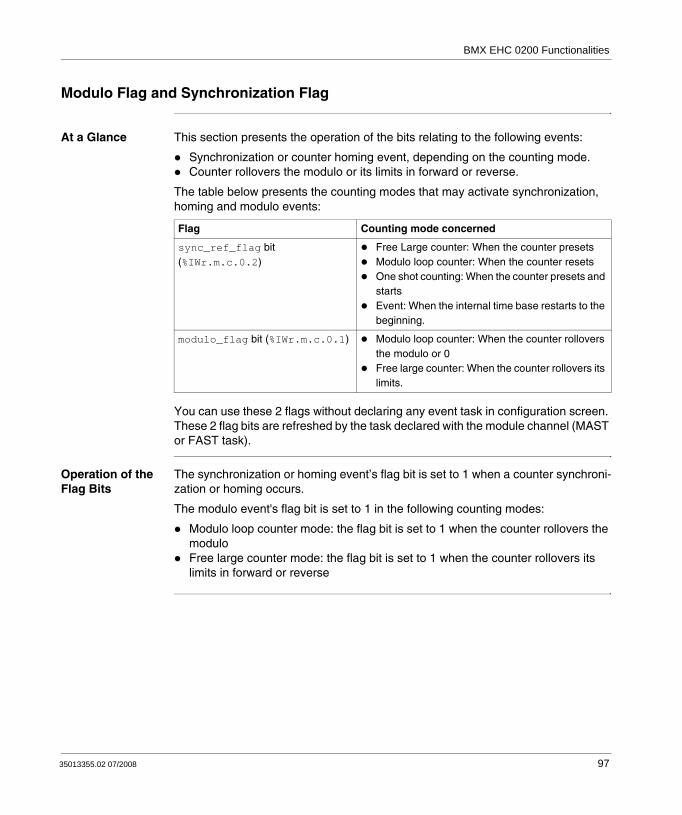
BMX EHC 0200 Functionalities
Modulo Flag and Synchronization Flag
At a Glance This section presents the operation of the bits relating to the following events:
Synchronization or counter homing event, depending on the counting mode.Counter rollovers the modulo or its limits in forward or reverse.
The table below presents the counting modes that may activate synchronization, homing and modulo events:
You can use these 2 flags without declaring any event task in configuration screen. These 2 flag bits are refreshed by the task declared with the module channel (MAST or FAST task).
Operation of the Flag Bits
The synchronization or homing event’s flag bit is set to 1 when a counter synchroni-zation or homing occurs.
The modulo event's flag bit is set to 1 in the following counting modes:
Modulo loop counter mode: the flag bit is set to 1 when the counter rollovers the moduloFree large counter mode: the flag bit is set to 1 when the counter rollovers its limits in forward or reverse
Flag Counting mode concerned
sync_ref_flag bit (%IWr.m.c.0.2)
Free Large counter: When the counter presetsModulo loop counter: When the counter resetsOne shot counting: When the counter presets and startsEvent: When the internal time base restarts to the beginning.
modulo_flag bit (%IWr.m.c.0.1) Modulo loop counter: When the counter rollovers the modulo or 0Free large counter: When the counter rollovers its limits.
35013355.02 07/2008 97

BMX EHC 0200 Functionalities
Location of the Flag Bits
The following table presents the modulo_flag and sync_ref_flag bits which are elements of the %IWr.m.c.d status word:
Resetting the Flag Bits to 0
The user application must reset the flag bit to 0 (if it is active) by using the appropriate command bit from the following two bits:
sync_reset bit to reset the synchronization or homing event's flag bit to 0modulo_reset bit to reset the modulo reached event's flag bit to 0
Location of Reset to 0 Commands
The following table presents the sync_reset and modulo_reset bits which are elements of the %Qr.m.c.d output command word:
Language object
Standard symbol Meaning
%IWr.m.c.0.0 RUN The counter operates in one shot mode only
%IWr.m.c.0.1 MODULO_FLAG Flag set to 1 by a modulo switch event
%IWr.m.c.0.2 SYNC_REF_FLAG Flag set to 1 by a preset or synchronization event
%IWr.m.c.0.3 VALIDITY The current numerical value is valid
%IWr.m.c.0.4 HIGH_LIMIT The current numerical value is locked at the upper threshold value
%IWr.m.c.0.5 LOW_LIMIT The current numerical value is locked at the lower threshold value
Language object
Standard symbol Meaning
%Qr.m.c.0 OUTPUT_0 Forces OUTPUT_0 to level 1
%Qr.m.c.1 OUTPUT_1 Forces OUTPUT_1 to level 1
%Qr.m.c.2 OUTPUT_BLOCK_0_ENABLE Implementation of output 0 function block
%Qr.m.c.3 OUTPUT_BLOCK_1_ENABLE Implementation of output 1 function block
%Qr.m.c.4 FORCE_SYNC Counting function synchronization and start
%Qr.m.c.5 FORCE_REF Set to preset counter value
%Qr.m.c.6 FORCE_ENABLE Implementation of counter
%Qr.m.c.7 FORCE_RESET Reset counter
%Qr.m.c.8 SYNC_RESET Reset SYNC_REF_FLAG
%Qr.m.c.9 MODULO_RESET Reset MODULO_FLAG
98 35013355.02 07/2008
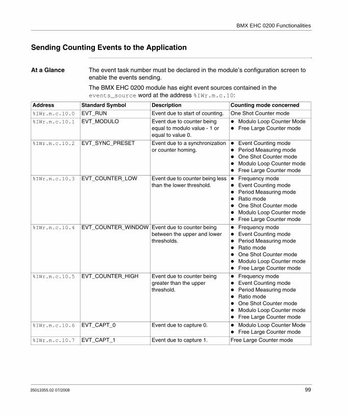
BMX EHC 0200 Functionalities
Sending Counting Events to the Application
At a Glance The event task number must be declared in the module’s configuration screen to enable the events sending.
The BMX EHC 0200 module has eight event sources contained in the events_source word at the address %IWr.m.c.10:
Address Standard Symbol Description Counting mode concerned
%IWr.m.c.10.0 EVT_RUN Event due to start of counting. One Shot Counter mode
%IWr.m.c.10.1 EVT_MODULO Event due to counter being equal to modulo value - 1 or equal to value 0.
Modulo Loop Counter ModeFree Large Counter mode
%IWr.m.c.10.2 EVT_SYNC_PRESET Event due to a synchronization or counter homing.
Event Counting modePeriod Measuring modeOne Shot Counter modeModulo Loop Counter modeFree Large Counter mode
%IWr.m.c.10.3 EVT_COUNTER_LOW Event due to counter being less than the lower threshold.
Frequency modeEvent Counting modePeriod Measuring modeRatio modeOne Shot Counter modeModulo Loop Counter modeFree Large Counter mode
%IWr.m.c.10.4 EVT_COUNTER_WINDOW Event due to counter being between the upper and lower thresholds.
Frequency modeEvent Counting modePeriod Measuring modeRatio modeOne Shot Counter modeModulo Loop Counter modeFree Large Counter mode
%IWr.m.c.10.5 EVT_COUNTER_HIGH Event due to counter being greater than the upper threshold.
Frequency modeEvent Counting modePeriod Measuring modeRatio modeOne Shot Counter modeModulo Loop Counter modeFree Large Counter mode
%IWr.m.c.10.6 EVT_CAPT_0 Event due to capture 0. Modulo Loop Counter ModeFree Large Counter mode
%IWr.m.c.10.7 EVT_CAPT_1 Event due to capture 1. Free Large Counter mode
35013355.02 07/2008 99

BMX EHC 0200 Functionalities
All the events sent by the module, whatever their source, call the same single event task in the PLC.
There is normally only one type of event indicated per call.
The evt_sources word (%IWr.m.c.10) is updated at the start of the event task processing.
Enabling Events In order for a source to produce an event, the validation bit corresponding to the event must be set to 1:
Input Interface The event only has one input interface. This interface is only updated at the start of the event task processing. The interface consists of:
The evt_sources word (%IWr.m.c.10)The current value of the counter during the event (or an approximate value) contained in the counter_value word (%IDr.m.c.12)The capt_0_val register (%IDr.m.c.14) updated if the event is the capture 0The capt_1_val register (%IDr.m.c.16) updated if the event is the capture 1
%IWr.m.c.10.8 EVT_OVERRUN Event due to overrun Frequency modeEvent Counting modePeriod Measuring modeRatio modeOne Shot Counter modeModulo Loop Counter modeFree Large Counter mode
Address Standard Symbol Description Counting mode concerned
Address Description
%QWr.m.c.1.0 Start of counting event validation bit.
%QWr.m.c.1.1 Counter rollovering modulo, 0 or its limits event validation bit.
%QWr.m.c.1.2 Synchronization or counter homing event validation bit.
%QWr.m.c.1.3 Counter less than lower threshold event validation bit.
%QWr.m.c.1.4 Counter between the upper and lower thresholds event validation bit.
%QWr.m.c.1.5 Counter greater than upper threshold event validation bit.
%QWr.m.c.1.6 Capture 0 event validation bit.
%QWr.m.c.1.7 Capture 1 event validation bit.
100 35013355.02 07/2008

BMX EHC 0200 Functionalities
Operating Limits Each counter channel can produce a maximum of one event per millisecond, but this flow may be slowed down by simultaneously sending events to several modules on the PLC bus.
Each counter channel has a four slot transmission buffer which can be used to store several events while waiting to be sent.
If the channel is unable to send all of the internally produced events, the overrun_evt bit (%IWr.m.c.10.8) of the evt_sources word is set to 1.
35013355.02 07/2008 101

BMX EHC 0200 Functionalities
7.2 BMX EHC 0200 Module Operation Modes
At a Glance
Subject of this Section
This section deals with the different counting modes of the BMX EHC 0200 module.
What's in this Section?
This section contains the following topics:
Topic Page
BMX EHC 0200 Module Operation in Frequency Mode 103
BMX EHC 0200 Module Operation in Event Counting Mode 104
BMX EHC 0200 Module Operation in Period Measuring Mode 106
BMX EHC 0200 Module Operation in Ratio Mode 109
BMX EHC 0200 Module Operation in One Shot Counter Mode 111
BMX EHC 0200 Module Operation in Modulo Loop Counter Mode 115
BMX EHC 0200 Module Operation in Free Large Counter Mode 119
BMX EHC 0200 Module Operation in Pulse Width Modulation Mode 128
102 35013355.02 07/2008
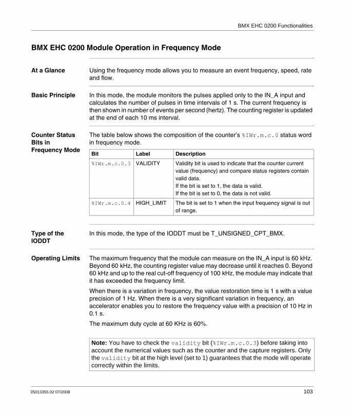
BMX EHC 0200 Functionalities
BMX EHC 0200 Module Operation in Frequency Mode
At a Glance Using the frequency mode allows you to measure an event frequency, speed, rate and flow.
Basic Principle In this mode, the module monitors the pulses applied only to the IN_A input and calculates the number of pulses in time intervals of 1 s. The current frequency is then shown in number of events per second (hertz). The counting register is updated at the end of each 10 ms interval.
Counter Status Bits in Frequency Mode
The table below shows the composition of the counter’s %IWr.m.c.0 status word in frequency mode.
Type of the IODDT
In this mode, the type of the IODDT must be T_UNSIGNED_CPT_BMX.
Operating Limits The maximum frequency that the module can measure on the IN_A input is 60 kHz. Beyond 60 kHz, the counting register value may decrease until it reaches 0. Beyond 60 kHz and up to the real cut-off frequency of 100 kHz, the module may indicate that it has exceeded the frequency limit.
When there is a variation in frequency, the value restoration time is 1 s with a value precision of 1 Hz. When there is a very significant variation in frequency, an accelerator enables you to restore the frequency value with a precision of 10 Hz in 0.1 s.
The maximum duty cycle at 60 KHz is 60%.
Bit Label Description
%IWr.m.c.0.3 VALIDITY Validity bit is used to indicate that the counter current value (frequency) and compare status registers contain valid data.If the bit is set to 1, the data is valid.If the bit is set to 0, the data is not valid.
%IWr.m.c.0.4 HIGH_LIMIT The bit is set to 1 when the input frequency signal is out of range.
Note: You have to check the validity bit (%IWr.m.c.0.3) before taking into account the numerical values such as the counter and the capture registers. Only the validity bit at the high level (set to 1) guarantees that the mode will operate correctly within the limits.
35013355.02 07/2008 103

BMX EHC 0200 Functionalities
BMX EHC 0200 Module Operation in Event Counting Mode
At a Glance Using the event counting mode allows you to determine the number of events received in a scattered manner.
Basic Principle In this mode, the counter assesses the number of pulses applied at the IN_A input, at time intervals defined by the user. The counting register is updated at the end of each interval with the number of events received.
It is possible to use the IN_SYNC input over a time interval, provided that the validation bit is set to 1. This restarts the event counting for a new predefined time interval. Depending on the selection made by the user, the time interval starts at the rising edge or at the falling edge on the IN_SYNC input.
Operation The trend diagram below illustrates the counting process in event counting mode:
IN_A input
IN_SYNC input
valid_sync bit
Internal time base
Current counter value
User defined
1 2 3 4 1 2 1 2 3 4 5
X 4 5
104 35013355.02 07/2008

BMX EHC 0200 Functionalities
Counter Status Bits in Event Counting Mode
The table below shows the composition of the counter’s %IWr.m.c.0 status word in event counting mode:
Type of the IODDT
In this mode, the type of the IODDT must be T_UNSIGNED_CPT_BMX.
Operating Limits The module counts the pulses applied at the IN_A input every time the pulse duration is greater than 5 μs (without debounce filter).
The synchronization of the counter must not be done more than one time per 5 ms.
Bit Label Description
%IWr.m.c.0.2 SYNC_REF_FLAG The bit is set to 1 when the internal time base has been synchronized.The bit is set to 0 when the sync_reset command is received (rising edge of the %Qr.m.c.8 bit).
%IWr.m.c.0.3 VALIDITY Validity bit is used to indicate that the counter current value (events number) and compare status registers contain valid data.If the bit is set to 1, the data is valid.If the bit is set to 0, the data is not valid.
%IWr.m.c.0.4 HIGH_LIMIT The bit is set to 1 when the number of received events exceeds the counter size.The bit is reset to 0 at the next period if the limit is not reached.
%IWr.m.c.0.5 LOW_LIMIT The bit is set to 1 when more than one synchronization is received within 5 ms period.The bit is reset to 0 at the next period if the limit is not reached.
Note: You have to check the validity bit (%IWr.m.c.0.3) before taking into account the numerical values such as the counter and the capture registers. Only the validity bit at the high level (set to 1) guarantees that the mode will operate correctly within the limits.
35013355.02 07/2008 105

BMX EHC 0200 Functionalities
BMX EHC 0200 Module Operation in Period Measuring Mode
At a Glance Using the period measuring mode allows you to:
determine the duration of an event.determine the time between two events.set and measure the execution time for a process.
Basic Principle This counting mode consists of two sub-modes:
Rising edge to falling edge mode (edge to opposite): allows you to measure the duration of an event.Rising edge to rising edge mode (edge to edge): allows you to measure the length of time between two events.
The user may also use the IN_SYNC input to enable or stop a measurement. The user may also specify a time out value in the configuration screen. This function allows to stop a measurement that exceeds this time out. In this case, the counting register is not valid until the next complete measurement.
The units used to measure the length of time of an event or between two events are defined by the user (1 μs, 100 μs or 1 ms).
Edge to Opposite Mode
In this sub-mode, the measurement is taken between the rising edge and the falling edge of the IN_A input. The counting register is updated as soon as the falling edge is detected.
The trend diagram below shows the operating mode of the edge to opposite sub-mode:
Duration A Duration B
IN_A input (Pulse)
Current counter value
A B
106 35013355.02 07/2008

BMX EHC 0200 Functionalities
Edge to Edge Mode
In this sub-mode, the measurement is taken between two rising edges of the IN_A input. The counting register is updated as soon as the second rising edge is detected.
The trend diagram below shows the operating mode of the edge to edge sub-mode:
Using the Synchronization Function
The trend diagram below illustrates the period measurement counting process in edge to opposite mode when using the synchronization function:
(1) The falling edge of the IN_SYNC input stops measurement C.(2) This pulse is not measured because the IN_SYNC input is not at the high level.
Period A Period B
IN_A input
Current counter value
BAX
(1)
X A B
A C B
IN_A input
IN_SYNC input
Current counter value
(2)
Note: The valid_sync bit (%QWr.m.c.0.0) must be set to 1 to enable the IN_SYNC input. If the IN_SYNC input is not wired, the application must force the setting of the force_sync bit (%Qr.m.c.4) to 1 to authorize the measurements.
35013355.02 07/2008 107

BMX EHC 0200 Functionalities
Counter Status Bits in Period Measuring Mode
The table below shows the composition of the counter’s %IWr.m.c.0 status word in period measuring mode:
Type of the IODDT
In this mode, the type of the IODDT must be T_UNSIGNED_CPT_BMX.
Operating Limits The module can perform a maximum of 1 measurement every 5 ms.
The shortest pulse that can be measured is 100 μs, even if the unit defined by the user is 1 μs.
The maximum duration that can be measured is 1,073,741,823 units (unit defined by the user).
Bit Label Description
%IWr.m.c.0.3 VALIDITY Validity bit is used to indicate that the counter current value (period value) and compare status registers contain valid data.If the bit is set to 1, the data is valid.If the bit is set to 0, the data is not valid.
%IWr.m.c.0.4 HIGH_LIMIT The bit is set to 1 when the measured period exceeds the user-defined timeout.The bit is reset to 0 at the next period if the timeout is not reached.
%IWr.m.c.0.5 LOW_LIMIT The bit is set to 1 when more than one measure occurs within 5 ms period.The bit is reset to 0 at the next period if the limit is not reached.
Note: You have to check the validity bit (%IWr.m.c.0.3) before taking into account the numerical values such as the counter and the capture registers. Only the validity bit at the high level (set to 1) guarantees that the mode will operate correctly within the limits.
108 35013355.02 07/2008
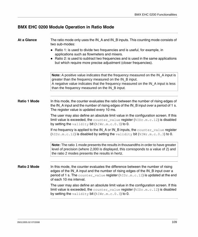
BMX EHC 0200 Functionalities
BMX EHC 0200 Module Operation in Ratio Mode
At a Glance The ratio mode only uses the IN_A and IN_B inputs. This counting mode consists of two sub-modes:
Ratio 1: is used to divide two frequencies and is useful, for example, in applications such as flowmeters and mixers.Ratio 2: is used to subtract two frequencies and is used in the same applications but which require more precise adjustment (closer frequencies).
Ratio 1 Mode In this mode, the counter evaluates the ratio between the number of rising edges of the IN_A input and the number of rising edges of the IN_B input over a period of 1 s. The register value is updated every 10 ms.
The user may also define an absolute limit value in the configuration screen. If this limit value is exceeded, the counter_value register (%IDr.m.c.12) is disabled by setting the validity bit (%IWr.m.c.0.3) to 0.
If no frequency is applied to the IN_A or IN_B inputs, the counter_value register (%IDr.m.c.12) is disabled by setting the validity bit (%IWr.m.c.0.3) to 0.
Ratio 2 Mode In this mode, the counter evaluates the difference between the number of rising edges of the IN_A input and the number of rising edges of the IN_B input over a period of 1 s. The counter_value register (%IDr.m.c.12) is updated at the end of each 10 ms interval.
The user may also define an absolute limit value in the configuration screen. If this limit value is exceeded, the counter_value register (%IDr.m.c.12) is disabled by setting the validity bit (%IWr.m.c.0.3) to 0.
Note: A positive value indicates that the frequency measured on the IN_A input is greater than the frequency measured on the IN_B input.A negative value indicates that the frequency measured on the IN_A input is less than the frequency measured on the IN_B input.
Note: The ratio 1 mode presents the results in thousandths in order to have greater level of precision (where 2,000 is displayed, this corresponds to a value of 2) and the ratio 2 modes presents the results in hertz.
35013355.02 07/2008 109

BMX EHC 0200 Functionalities
Counter Status Bits in Ratio Mode
The table below shows the composition of the counter’s %IWr.m.c.0 status word in ratio mode:
Type of the IODDT
In this mode, the type of the IODDT must be T_SIGNED_CPT_BMX.
Operating Limits The maximum frequency that the module can measure on the IN_A and IN_B inputs is 60 kHz.
The measured values are between -60,000,000,000 and +60,000,000,000.
Bit Label Description
%IWr.m.c.0.3 VALIDITY Validity bit is used to indicate that the counter current value (ratio value) and compare status registers contain valid data.If the bit is set to 1, the data is valid.If the bit is set to 0, the data is not valid.
%IWr.m.c.0.4 HIGH_LIMIT The bit signals a fault when the ratio exceeds the absolute limit.The bit is set to 1 when frequency to IN_A becomes too fast.The bit is reset to 0 when the frequency to IN_A remains correct.
%IWr.m.c.0.5 LOW_LIMIT The bit signals a fault when the ratio exceeds the absolute limit.The bit is set to 1 when frequency to IN_B becomes too fast.The bit is reset to 0 when the frequency to IN_B remains correct.
Note: You have to check the validity bit (%IWr.m.c.0.3) before taking into account the numerical values such as the counter and the capture registers. Only the validity bit at the high level (set to 1) guarantees that the mode will operate correctly within the limits.
110 35013355.02 07/2008
BMX EHC 0200 Functionalities
BMX EHC 0200 Module Operation in One Shot Counter Mode
At a Glance Using the one shot counter mode allows you to quantify a group of parts.
Basic Principle In this mode, activating the synchronization function starts the counter which, starting from a value defined by the user in the adjust screen (preset value), decreases with every pulse applied to the IN_A input until it reaches the value 0. Downcounting is made possible when the enable function is activated. The counting register is thus updated every 1 ms.
One basic use of this mode is, using an output, to indicate the end of a group of operations (when the counter reaches 0).
35013355.02 07/2008 111

BMX EHC 0200 Functionalities
Operation The trend diagram below illustrates the counting process in one shot counter mode:
In the trend diagram above, we can see that the counter is set to the preset value at the IN_SYNC input’s rising edge. Then, the counter decrements the counting register with every pulse applied to the IN_A input. When the register is set to 0, the counter awaits a new signal from the IN_SYNC input. The IN_A input pulses have no effect on the register value as long as the counter is set to 0.
The enable function must be activated during the counting by:
setting to 1 the force_enable bitsetting to 1 the valid_enable bit and when the IN_EN input is at the high level
When the enable function is deactivated, the last value reported in the counting register is maintained and the counter ignores the pulses applied to the IN_A input. However, it does not ignore the IN_SYNC input status.
Each time the counter starts a downcounting operation, the run bit switches to the high level. It switches to the low level when the register value reaches 0.
0
IN_A input (pulses)
IN_SYNC input
valid_syncbit
IN_EN input
valid_enablebit
Current counter value
User-defined value (preset value)
run counter operating bit
112 35013355.02 07/2008

BMX EHC 0200 Functionalities
Counter Status Bits in One shot Counter Mode
The table below shows the composition of the counter’s %IWr.m.c.0 status word in one shot counter mode:
Type of the IODDT
In this mode, the type of the IODDT must be T_UNSIGNED_CPT_BMX.
Note: The pulses applied to IN_SYNC and IN_EN inputs are only taken into account when the inputs are enabled (see Enable Function, p. 94).The value defined by the user (preset value) is contained in the word %MDr.m.c.6. The user may change this value by specifying the value of this word by configuring the parameter in the adjust screen or by using the WRITE_PARAM(IODDT_VAR1) Function. IODDT_VAR1 is of the type T_UNSIGNED_CPT_BMX. This value change is only taken into account by the module after one of the following conditions has been established:
At the next synchronization if the counter is stopped (run bit set to 0)At the second synchronization if the counter is activated (run bit set to 1).
Note: The maximum value of the preset value parameter is 4,294,967,295.
Bit Label Description
%IWr.m.c.0.0 RUN The bit is set to 1 when the counter is running.The bit is set to 0 when the counter is stopped.
%IWr.m.c.0.2 SYNC_REF_FLAG The bit is set to 1 when the counter has been set to the preset value and (re)started.The bit is reset to 0 when the sync_reset command is received (rising edge of the %Qr.m.c.8 bit).
%IWr.m.c.0.3 VALIDITY Validity bit is used to indicate that the counter current value and compare status registers contain valid data.If the bit is set to 1, the data is valid.If the bit is set to 0, the data is not valid.
35013355.02 07/2008 113

BMX EHC 0200 Functionalities
Operating Limits The maximum frequency that can be applied to the IN_SYNC input is 1 pulse every 5 ms.
The maximum value defined by the user (preset value) is 4,294,967,295.
Note: You have to check the validity bit (%IWr.m.c.0.3) before taking into account the numerical values such as the counter and the capture registers. Only the validity bit at the high level (set to 1) guarantees that the mode will operate correctly within the limits.
114 35013355.02 07/2008

BMX EHC 0200 Functionalities
BMX EHC 0200 Module Operation in Modulo Loop Counter Mode
At a Glance The use of the modulo loop counter mode is recommended for packaging and labeling applications for which actions are repeated for series of moving objects.
Basic Principle In the upcounting direction, the counter increases until it reaches the modulo value -1, the modulo value being defined by the user. At the following pulse in the counting direction, the counter is reset to 0 and the counting resumes.
In the downcounting direction, the counter decreases until it reaches 0. At the next pulse in the counting direction, the counter is reset to the the modulo value -1, the modulo value being defined by the user. The downcounting may then be resumed.
The enable function must be activated during the counting by:
Setting to 1 the force_enable bit (%Qr.m.c.6)Setting to 1 the valid_enable bit (%QWr.m.c.0.2) when the IN_EN input is at the high level
When the enable function is deactivated, the last value reported in the counting register is maintained and the counter ignores the pulses applied to the IN_A input. However, it does not ignore the preset condition.
In the modulo loop counter mode, the counter must be synchronized at least one time to operate. The current counter value is cleared each time the synchronization occurs.
The current counter value can be recorded into the capture0 register (see Capture Function, p. 96) when the condition of synchronization occurs (see Synchronization Function, p. 90).
The modulo value defined by the user is contained in the modulo_value word %MDr.m.c.4. The user may change this value by specifying the value of this word:
In the ajust screenIn the application, using the WRITE_PARAM(IODDT_VAR1) Function. IODDT_VAR1 is of the type T_UNSIGNED_CPT_BMX.
The new modulo value is acknowledged if one of the two following conditions is met:
The synchronization is activatedThe counter rollovers the value 0 in the downcounting direction or the modulo value -1 (this value is the modulo value recorded before editing the new modulo value) in the upcounting direction.
35013355.02 07/2008 115

BMX EHC 0200 Functionalities
Counting Interface
In this mode, the user may select one of the following counting configurations:
A = Up, B = Down (default configuration)A = Impulse, B = DirectionNormal Quadrature X1Normal Quadrature X2Normal Quadrature X4Reverse Quadrature X1Reverse Quadrature X2Reverse Quadrature X4.
The following table shows the upcounting and downcounting principle according to the selected configuration:
Selected configuration Counting condition Downcounting condition
A = Up, B = Down Rising edge at the IN_A input. Rising edge at the IN_B input.
A = Impulse, B = Direction Rising edge at the IN_A input and high level at the IN_B input.
Rising edge at the IN_A input and low state at the IN_B input.
Normal Quadrature X1 Rising edge at the IN_A input and low state at the IN_B input.
Falling edge at the IN_A input and low state at the IN_B input.
Normal Quadrature X2 Rising edge at the IN_A input and low state at the IN_B input.Falling edge at the IN_A input and high state at the IN_B input.
Falling edge at the IN_A input and low state at the IN_B input.Rising edge at the IN_A input and high level at the IN_B input.
Normal Quadrature X4 Rising edge at the IN_A input and low state at the IN_B input.High state at the IN_A input and rising edge at the IN_B input.Falling edge at the IN_A input and high state at the IN_B input.Low state at the IN_A input and falling edge at the IN_B input.
Falling edge at the IN_A input and low state at the IN_B input.Low state at the IN_A input and rising edge at the IN_B input.Rising edge at the IN_A input and high level at the IN_B input.High state at the IN_A input and falling edge at the IN_B input.
Reverse Quadrature X1 Falling edge at the IN_A input and low state at the IN_B input.
Rising edge at the IN_A input and low state at the IN_B input.
Reverse Quadrature X2 Falling edge at the IN_A input and low state at the IN_B input.Rising edge at the IN_A input and high level at the IN_B input.
Rising edge at the IN_A input and low state at the IN_B input.Falling edge at the IN_A input and high state at the IN_B input.
116 35013355.02 07/2008

BMX EHC 0200 Functionalities
Operation The trend diagram below illustrates the modulo counting process in the configuration by default:
Reverse Quadrature X4 Falling edge at the IN_A input and low state at the IN_B input.Low state at the IN_A input and rising edge at the IN_B input.Rising edge at the IN_A input and high level at the IN_B input.High state at the IN_A input and falling edge at the IN_B input.
Rising edge at the IN_A input and low state at the IN_B input.High state at the IN_A input and rising edge at the IN_B input.Falling edge at the IN_A input and high state at the IN_B input.Low state at the IN_A input and falling edge at the IN_B input.
Selected configuration Counting condition Downcounting condition
Capture0 value
Modulo value
Counter value
valid_sync bit
IN_B input (pulses)
IN_A input (pulses)
IN_SYNC input
X1 X2 X3
X3
X1
X2
0Time
35013355.02 07/2008 117
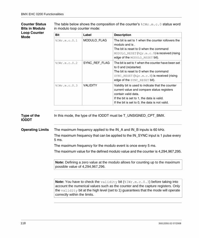
BMX EHC 0200 Functionalities
Counter Status Bits in Modulo Loop Counter Mode
The table below shows the composition of the counter’s %IWr.m.c.0 status word in modulo loop counter mode:
Type of the IODDT
In this mode, the type of the IODDT must be T_UNSIGNED_CPT_BMX.
Operating Limits The maximum frequency applied to the IN_A and IN_B inputs is 60 kHz.
The maximum frequency that can be applied to the IN_SYNC input is 1 pulse every 5 ms.
The maximum frequency for the modulo event is once every 5 ms.
The maximum value for the defined modulo value and the counter is 4,294,967,295.
Bit Label Description
%IWr.m.c.0.1 MODULO_FLAG The bit is set to 1 when the counter rollovers the modulo and is .The bit is reset to 0 when the command MODULO_RESET (%Qr.m.c.9) is received (rising edge of the MODULO_RESET bit).
%IWr.m.c.0.2 SYNC_REF_FLAG The bit is set to 1 when the counter have been set to 0 and (re)started.The bit is reset to 0 when the command SYNC_RESET (%Qr.m.c.8) is received (rising edge of the SYNC_RESET bit).
%IWr.m.c.0.3 VALIDITY Validity bit is used to indicate that the counter current value and compare status registers contain valid data.If the bit is set to 1, the data is valid.If the bit is set to 0, the data is not valid.
Note: Defining a zero value at the modulo allows for counting up to the maximum possible value of 4,294,967,296.
Note: You have to check the validity bit (%IWr.m.c.0.3) before taking into account the numerical values such as the counter and the capture registers. Only the validity bit at the high level (set to 1) guarantees that the mode will operate correctly within the limits.
118 35013355.02 07/2008

BMX EHC 0200 Functionalities
BMX EHC 0200 Module Operation in Free Large Counter Mode
At a Glance The use of the free large counter mode is especially recommended for axis monitoring or labeling where the incoming position of each part has to be learned.
Basic Principle The upcounting (or downcounting) starts as soon as the homing function is completed.
The enable function must be activated during the counting by:
Setting to 1 the force_enable bit (%Qr.m.c.6)Setting to 1 the valid_enable bit (%QWr.m.c.0.2) when the IN_EN input is at the high level.
When the enable function is deactivated, the last value reported in the counting register is maintained and the counter ignores the pulses applied to the IN_A input. However, it does not ignore the preset condition.
In the free large counter mode, the counter must be preset at least one time to operate. The current counter value is load with the preset_value each time the preset condition occurs.
The current counter can be recorded into the capture0 register when the preset condition occurs or using the IN_CAP input.
The current counter value can be stored into the capture1 register using the IN_CAP input.
For further information, you may see the synchronization function (see Synchroni-zation Function, p. 90) and the capture function (see Capture Function, p. 96).
In the free large counter mode, the counting register is updated at 1 ms intervals.
35013355.02 07/2008 119

BMX EHC 0200 Functionalities
Counting Configurations
In this mode, the user may select one of the following counting configurations:
A = Up, B = Down (default configuration)A = Impulse, B = DirectionNormal Quadrature X1Normal Quadrature X2Normal Quadrature X4Reverse Quadrature X1Reverse Quadrature X2Reverse Quadrature X4
The following table shows the upcounting and downcounting principle according to the selected configuration:
Selected configuration Counting condition Downcounting condition
A = Up, B = Down (default configuration)
Rising edge of the IN_A input. Rising edge of the IN_B input.
A = Impulse, B = Direction Rising edge of the IN_A input and high level at the IN_B input.
Rising edge of the IN_A input and low state at the IN_B input.
Normal Quadrature X1 Rising edge of the IN_A input and low state at the IN_B input.
Falling edge of the IN_A input and low state at the IN_B input.
Normal Quadrature X2 Rising edge of the IN_A input and low state at the IN_B input.Falling edge of the IN_A input and high state at the IN_B input.
Falling edge of the IN_A input and low state at the IN_B input.Rising edge of the IN_A input and high level at the IN_B input.
Normal Quadrature X4 Rising edge of the IN_A input and low state at the IN_B input.High state at the IN_A input and rising edge of the IN_B input.Falling edge of the IN_A input and high state at the IN_B input.Low state at the IN_A input and falling edge of the IN_B input.
Falling edge of the IN_A input and low state at the IN_B input.Low state at the IN_A input and rising edge of the IN_B input.Rising edge of the IN_A input and high level at the IN_B input.High state at the IN_A input and falling edge of the IN_B input.
Reverse Quadrature X1 Falling edge of the IN_A input and low state at the IN_B input.
Rising edge of the IN_A input and low state at the IN_B input.
Reverse Quadrature X2 Falling edge of the IN_A input and low state at the IN_B input.Rising edge of the IN_A input and high level at the IN_B input.
Rising edge of the IN_A input and low state at the IN_B input.Falling edge of the IN_A input and high state at the IN_B input.
120 35013355.02 07/2008

BMX EHC 0200 Functionalities
Homing Function This function allows to record the current_counter_value register in the capt_0_val register and/or to set the current_counter_value register to the user-predefined parameter preset_value.
The value defined by the user as preset_value is contained in the %MDr.m.c.4 word.
The user may change this value by specifying the value of this word:
In the ajust screenIn the application, by using the WRITE_PARAM(IODDT_VAR1) Function. IODDT_VAR1 is of the type T_SIGNED_CPT_BMX.
For further information, you may see the homing function (see Homing Function, p. 92) and the capture function (see Capture Function, p. 96).
The module configuration enables you to select the following homing conditions:
Rising edge of the IN_SYNC input (default)Rising edge of the IN_REF inputRising edge of the IN_SYNC input at the IN_REF input’s high level:
Reverse Quadrature X4 Falling edge of the IN_A input and low state at the IN_B input.Low state at the IN_A input and rising edge of the IN_B input.Rising edge of the IN_A input and high level at the IN_B input.High state at the IN_A input and falling edge of the IN_B input.
Rising edge of the IN_A input and low state of the IN_B input.High state of the IN_A input and rising edge of the IN_B input.Falling edge of the IN_A input and high state of the IN_B input.Low state of the IN_A input and falling edge of the IN_B input.
Selected configuration Counting condition Downcounting condition
moment when the homing is carried out
Homing 4 consecutive homings
IN_SYNC input
Nohoming
IN_REF input
Time
35013355.02 07/2008 121

BMX EHC 0200 Functionalities
First rising edge of the IN_SYNC input and high level at the IN_REF input
First rising edge of the IN_SYNC input and low level at the IN_REF input
Homing only on the first rising edge
Nohoming
IN_SYNC input
IN_REF input
Time
moment when the homing is carried out
Nohoming
Homing only on the first rising edge
IN_SYNC input
IN_REF input
Time
moment when the homing is carried out
122 35013355.02 07/2008

BMX EHC 0200 Functionalities
Operation The trend diagram below illustrates the counting process for a free large counter in the configuration by default:
IN_A input (pulses)
IN_B input (pulses)
Enable condition
IN_CAP input
Preset value
Counter value
Preset condition
Capture0 value
X3
X3X1
X2
0
Time
Capture1 value
X3X2X1
35013355.02 07/2008 123

BMX EHC 0200 Functionalities
Behavior at the Counting Limits
When the upper or lower limit is exceeded, the counter behaves differently according to its configuration.
In the lock on limits default configuration, the counting register maintains the limit value once it has been reached and the counting validity bit changes to 0 until the next preset condition occurs:
In the rollover configuration, the counting register switches to the opposite limit value when one of the two limits is exceeded:
Note: Overflow or underflow is indicated by two bits LOW_LIMIT and HIGH_LIMIT until the application reloads the counting value predefined by the user (force_ref bit set to 1 or preset condition true). The upcounting or downcounting may therefore resume.
Homing event
Counter value Lock on limits mode
Validity bit
-2M
0
+ 2M
Homing event
Counter value Rollover mode
Validity bit
- 2M
0
+ 2M+ 2M
- 2M
124 35013355.02 07/2008

BMX EHC 0200 Functionalities
Slack Delete In the free large counter mode, the counter may apply a hysteresis if the rotation is inverted. The hysteresis parameter configured with the adjust screen defines the number of points that are not acknowledged by the counter during the rotation inversion. This aims to take into account the slack between the encoder/motor axis and the mechanical axis (e.g. an encoder measuring the position of a mat).
This behavior is described in the following figure:
The value defined by the user as the Hysteresis (slack) value is contained in the %MWr.m.c.9 word. The user may change this value by specifying the value of this word (this value is from 0 to 255):
In the adjust screenIn the application by using the WRITE_PARAM(IODDT_VAR1) Function. IODDT_VAR1 is of the type T_SIGNED_CPT_BMX.
Encoder forward motion
Counter value
Hysteresis Hysteresis
Mechanical forward motion
Encoder return motion
Mechanical return motion
Encoder forward motion
Mechanical forward motion
35013355.02 07/2008 125

BMX EHC 0200 Functionalities
Counter Status Bits in Free Large Counter Mode
The table below shows the composition of the counter’s %IWr.m.c.0 status word in free large counter mode:
Type of the IODDT
In this mode, the type of the IODDT must be T_SIGNED_CPT_BMX.
Bit Label Description
%IWr.m.c.0.1 MODULO_FLAG The bit status changes in the rollover mode.The bit is set to 1 when the counter rollovers its limits (-2,147,483,648 or +2,147,483,647).The bit is reset to 0 when the command MODULO_RESET (%Qr.m.c.9) is received (rising edge of the MODULO_RESET bit).
%IWr.m.c.0.2 SYNC_REF_FLAG The bit is set to 1 when the counter have been set to the preset value and (re)started.The bit is reset to 0 when the command SYNC_RESET (%Qr.m.c.8) is received (rising edge of the SYNC_RESET bit).
%IWr.m.c.0.3 VALIDITY Validity bit is used to indicate that the counter current value and compare status registers contain valid data.If the bit is set to 1, the data is valid.If the bit is set to 0, the data is not valid.
%IWr.m.c.0.4 HIGH_LIMIT The bit status changes in the lock on limits mode.The bit is set to 1 when the counter reaches +2,147,483,647.The bit is reset to 0 when the counter presets or resets.
%IWr.m.c.0.5 LOW_LIMIT The bit status changes in the lock on limits mode.The bit is set to 1 when the counter reaches -2,147,483,648.The bit is reset to 0 when the counter presets or resets.
126 35013355.02 07/2008

BMX EHC 0200 Functionalities
Operating Limits The maximum frequency simultaneously applied to the IN_A and IN_B inputs is 60 kHz.
The shortest pulse applied to the IN_SYNC input is 100 μs.
The maximum homing event frequency is once every 5 ms.
The counter value is between -2,147,483,648 and +2,147,483,647.
Note: You have to check the validity bit (%IWr.m.c.0.3) before taking into account the numerical values such as the counter and the capture registers. Only the validity bit at the high level (set to 1) guarantees that the mode will operate correctly within the limits.
35013355.02 07/2008 127

BMX EHC 0200 Functionalities
BMX EHC 0200 Module Operation in Pulse Width Modulation Mode
At a Glance In this operating mode, the module uses an internal clock generator to supply a periodic signal at the module’s Q0 output. Only the Q0 output is concerned by this mode as the Q1 output is independent of this mode.
Basic Principle The output_block_0_enable command bit (%Qr.m.c.2) must be set to 1 in order to enable a modulation at the Q0 output.
The active validation function enables the operation of the internal clock generator that produces the output signal to be validated.
The active synchronization function enables the output signal to be synchronized by resetting to 0 the internal clock generator.
The wave form of the output signal depends on:
The pwm_frequency value (%QDr.m.c.6): it defines the frequency from 0.1 Hz (value is equal to 1) to 4 KHz (value is equal to 40,000), in increments of 0.1 HzThe pwm_duty value (%QWr.m.c.8): it defines the duty cycle from 5 % (value is equal to 1) to 95 % (value is equal to 19) in increments of 5 %.
The following figure shows the operation of the module in the pulse width modulation mode:
Q0 output
Frequency
Duty cycle
Validation functionSynchronization function
128 35013355.02 07/2008

BMX EHC 0200 Functionalities
Counter Status Bits in Pulse Width Modulation Mode
The table below shows the composition of the counter’s %IWr.m.c.0 status word in pulse width modulation mode:
Type of the IODDT
In this mode, the type of the IODDT must be T_UNSIGNED_CPT_BMX.
Bit Label Description
%IWr.m.c.0.3 VALIDITY Validity bit is used to indicate that the output data (frequency and duty cycle) unter current value and compare status registers contain valid data.If the bit is set to 1, the data is valid.If the bit is set to 0, the data is not valid.
%IWr.m.c.0.4 HIGH_LIMIT The output frequency or the duty cycle is out of range (high limit).
%IWr.m.c.0.5 LOW_LIMIT The output frequency or the duty cycle is out of range (low limit).
35013355.02 07/2008 129
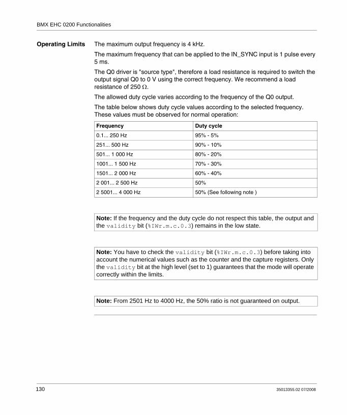
BMX EHC 0200 Functionalities
Operating Limits The maximum output frequency is 4 kHz.
The maximum frequency that can be applied to the IN_SYNC input is 1 pulse every 5 ms.
The Q0 driver is "source type", therefore a load resistance is required to switch the output signal Q0 to 0 V using the correct frequency. We recommend a load resistance of 250 Ω.
The allowed duty cycle varies according to the frequency of the Q0 output.
The table below shows duty cycle values according to the selected frequency. These values must be observed for normal operation:
Frequency Duty cycle
0.1... 250 Hz 95% - 5%
251... 500 Hz 90% - 10%
501... 1 000 Hz 80% - 20%
1001... 1 500 Hz 70% - 30%
1501... 2 000 Hz 60% - 40%
2 001... 2 500 Hz 50%
2 5001... 4 000 Hz 50% (See following note )
Note: If the frequency and the duty cycle do not respect this table, the output and the validity bit (%IWr.m.c.0.3) remains in the low state.
Note: You have to check the validity bit (%IWr.m.c.0.3) before taking into account the numerical values such as the counter and the capture registers. Only the validity bit at the high level (set to 1) guarantees that the mode will operate correctly within the limits.
Note: From 2501 Hz to 4000 Hz, the 50% ratio is not guaranteed on output.
130 35013355.02 07/2008

35013355.02 07/2008
8
BMX EHC 0800 Counting Module FunctionalitiesAt a Glance
Subject of this Section
This section deals with functionalities and counting modes of the BMX EHC 0800 module.
What's in this Chapter?
This chapter contains the following sections:
Section Topic Page
8.1 BMX EHC 0800 Module Functionalities 132
8.2 BMX EHC 0800 Module Operation Modes 148
131

BMX EHC 0800 Functionalities
8.1 BMX EHC 0800 Module Functionalities
At a Glance
Subject of this Section
This section deals with the functionalities of the BMX EHC 0800 module.
What's in this Section?
This section contains the following topics:
Topic Page
Input Interface Blocks 133
Programmable Filtering 134
Comparison 135
Diagnostics 137
Synchronization, Enable, Reset to 0 and Capture Functions 138
Modulo Flag and Synchronization Flag 144
Sending Counting Events to the Application 146
132 35013355.02 07/2008

BMX EHC 0800 Functionalities
Input Interface Blocks
Description The BMX EHC 0800 counting module has three fast inputs:
Fast Inputs The table below presents the module’s fast inputs.
Input Use with available sensors Use with an encoder
IN_A input Clock input for measurement or single upcounting For signal A
IN_B inputFrom the following channel
Second clock input for differential counting or measurement For signal B
IN_AUX input Multi-function input used for:synchronizationpreset and startreset and recordcapturecounting direction (upcounting/downcounting mode)
For signal ZUsed for preset
35013355.02 07/2008 133

BMX EHC 0800 Functionalities
Programmable Filtering
At a Glance The BMX EHC 0800 counting module’s two (or three) inputs are compatible with the use of mechanical switches.
A programmable debounce filter with 3 levels (low, medium and high) is available at every input.
Debounce Filter Diagram
The figure below shows the debounce filter in low mode:
In this mode, the system delays all transitions until the signal is stable for 450 μs.
Selecting the Filtering Level
The table below specifies the characteristics of each input for the selected level of filtering:
450 μs 450 μs
Input
Filtered signal
Filtering level Input Minimum pulse
Maximum frequency
None IN_A, IN_B 50 μs 10 KHz
IN_AUX 50 μs 40 Hz
Lowfor bounces > 2 KHz
IN_A, (IN_B) 450 μs 1 KHz
IN_AUX 450 μs 40 Hz
Resourcefor bounces > 1 KHz
IN_A, IN_B 1.25 ms 350 Hz
IN_AUX 1.25 μs 40 Hz
Highfor bounces > 250 Hz
IN_A, IN_B 4.2 ms 100 Hz
IN_AUX 4.2 ms 40 Hz
134 35013355.02 07/2008

BMX EHC 0800 Functionalities
Comparison
At a Glance The comparison block operates automatically when it is enabled. It is available in all the BMX EHC 0800 module’s counting modes.
It compares the current value of the counter together with the capture value at the defined threshold.
Comparison Threshold
The comparison block has one threshold only. Its value is contained in the lower_th_value double word (%QDr.m.c.2).
The threshold format is identical to the counter value format.
Comparison Status Register
The result of the comparison is stored in the comparison status register.
The value of the capture register and the current value of the counter are compared with the thresholds.
The possible results are:
Low: The counter value is less than the lower threshold value.Equal: The counter value is equal to the threshold.High: The counter value is greater than the threshold.
The comparison status register consists of:
Position of the status register bit
15 14 13 12 11 10 9 8 7 6 5 4 3 2 1 0
Compared element
Capture Counter
Comparison result
High Equal Low High Equal Low
35013355.02 07/2008 135

BMX EHC 0800 Functionalities
Update When the compare_enable_bit is set to 0, the comparison status register is deleted.
When the compare_suspend_bit is set to 1, the comparison status register is frozen at its last value.
The comparison with capture register value is performed every time the registers are loaded.
The comparison with the counter current value is performed as follows:
Counting mode Comparison register update
Frequency Period intervals of 10 ms
Event counting Period intervals defined by the user
Modulo loop counter One of the following conditions:intervals of 5 mscounter reloading or resetting to 0counting direction changecounter stopscrossing of threshold
One shot counter
dual phase counting
Up and down counting
136 35013355.02 07/2008

BMX EHC 0800 Functionalities
Diagnostics
Consistency Rules for Inputs Interface
The input interface requires that the sensor power supply remains active for counting operations.
When the sensor power supply interrupts lasts 1 ms or less, the counter remains stable.
In case of power interrupt is greater than 1 ms, all counter values are disabled.
By default, the sensor supply fault makes the CH_ERROR (%Ir.m.c.ERR) global status bit at the high level and the red led IO lighted.
The configuration screen allows to unlink the sensor supply fault to the CH_ERROR bit by configuring the parameter Input Supply Fault as local instead of General IO Fault.
In all cases, after having executed the READ_STS (IODDT_VAR1) instruction, the application provides the %MWr.m.c.2 and %MWr.m.c.3 standard status words including the supply fault information.
IODDT_VAR1 is of the type T_Unsigned_CPT_BMX or T_Signed_CPT_BMX.
Explicit channel status words
The table below presents the composition of the %MWr.m.c.2 and %MWr.m.c.3 status words.
I/O Data All input/output statuses are provided in the channel data bits.
The table below shows the channel data bits:
Status Word Bit position Designation
%MWr.m.c.2 0 External fault at inputs
4 Internal error or self-testing.
5 Configuration Fault
6 Communication Error
7 Application fault
%MWr.m.c.3 2 Sensor supply fault
Input/Output data field Designation
%Ir.m.c.4 Electrical state of IN_A input
%Ir.m.c.5 Electrical state of IN_B input
%Ir.m.c.6 Electrical state of IN_AUX input
35013355.02 07/2008 137

BMX EHC 0800 Functionalities
Synchronization, Enable, Reset to 0 and Capture Functions
Introduction This section presents the functions used by the various counting modes of the BMX EHC 0800 module:
Synchronization functionEnable functionReset to 0 functionCapture function
Each function uses at least one of the following two bits:
valid_(function) bit: Setting this bit to 1 allows you to take into account the occurrence of an external event which activates the function. If this bit is set to 0, the event is not taken into account and does not activate the function. The functions_enabling word (%QWr.m.c.0) contains all the valid_(function) bits.force_(function) bit: Setting this bit to 1 allows you to activate the function irrespective of the status of the external event. All the force_(function) bits are %Qr.m.c.4...%Qr.m.c.8 language objects.
138 35013355.02 07/2008

BMX EHC 0800 Functionalities
Synchronization Function
The synchronization function is used to synchronize the counter operation upon a transition applied to the IN_AUX physical input or the force_sync bit set to 1.
This function is used in the following counting modes:
Dual phase countingModulo loop counterOne shot counterEvent countingUp and down counting (using the force_sync bit only)
In all of the counting modes specified above, with the exception of the up and down counting mode, the user may configure the synchro edge parameter in the configuration screen by choosing from the following two possibilities to configure the external event:
Rising edge of the IN_AUX inputFalling edge of the IN_AUX input
The following table presents the force_sync bit in bold which is an element of the %Qr.m.c.d output command word:
Language object
Standard symbol Meaning
%Qr.m.c.0 OUTPUT_0 Forces OUTPUT_0 to level 1
%Qr.m.c.1 OUTPUT_1 Forces OUTPUT_1 to level 1
%Qr.m.c.2 OUTPUT_BLOCK_0_ENABLE Implementation of output 0 function block
%Qr.m.c.3 OUTPUT_BLOCK_1_ENABLE Implementation of output 1 function block
%Qr.m.c.4 FORCE_SYNC Counting function synchronization and start
%Qr.m.c.5 FORCE_REF Set to preset counter value
%Qr.m.c.6 FORCE_ENABLE Implementation of counter
%Qr.m.c.7 FORCE_RESET Reset counter
%Qr.m.c.8 SYNC_RESET Reset SYNC_REF_FLAG
%Qr.m.c.9 MODULO_RESET Reset MODULO_FLAG
35013355.02 07/2008 139

BMX EHC 0800 Functionalities
The following table presents the valid_sync bit in bold which is an element of the %QWr.m.c.0 function enabling word:
The following table presents the synchronization principle:
When the synchronization occurs, the application can react using :
either the SYNC_REF_FLAG input (%IWr.m.c.0.2) (see Modulo Flag and Synchronization Flag, p. 97)or the EVT_SYNC_PRESET input (%IWr.m.c.10.2) (see Sending Counting Events to the Application, p. 99).
Language object
Standard symbol Meaning
%QWr.m.c.0.0 VALID_SYNC Synchronization and start authorization for the counting function via the IN_SYNC input
%QWr.m.c.0.1 VALID_REF Operation authorization for the internal preset function
%QWr.m.c.0.2 VALID_ENABLE Authorization of the counter enable via the IN_EN input
%QWr.m.c.0.3 VALID_CAPT_0 Capture authorization in the capture0 register
%QWr.m.c.0.4 VALID_CAPT_1 Capture authorization in the capture1 register
%QWr.m.c.0.5 COMPARE_ENABLE Comparators operation authorization
%QWr.m.c.0.6 COMPARE_SUSPEND Comparator frozen at its last value
Edge Status of the valid_sync bit
Status of the counter
Rising or falling edge on IN_AUX (depending on the configuration)
Set to 0 Not synchronized
Rising or falling edge on IN_AUX (depending on the configuration)
Set to 1 Synchronized
Rising edge on force_sync bit Set to 0 or 1 Synchronized
140 35013355.02 07/2008

BMX EHC 0800 Functionalities
Enable Function This function is used to authorize changes to the counter value via software command.
This function is used in the following counting modes:
Dual phase countingUp and down countingModulo loop counterOne shot counter
The following table presents the force_enable bit in bold which is an element of the %Qr.m.c.d output command word:
The function is activated by setting the force_enable bit to 1. There is no valid_enable bit because the function is not activated by any physical input.
Language object
Standard symbol Meaning
%Qr.m.c.0 OUTPUT_0 Forces OUTPUT_0 to level 1
%Qr.m.c.1 OUTPUT_1 Forces OUTPUT_1 to level 1
%Qr.m.c.2 OUTPUT_BLOCK_0_ENABLE Implementation of output 0 function block
%Qr.m.c.3 OUTPUT_BLOCK_1_ENABLE Implementation of output 1 function block
%Qr.m.c.4 FORCE_SYNC Counting function synchronization and start
%Qr.m.c.5 FORCE_REF Set to preset counter value
%Qr.m.c.6 FORCE_ENABLE Implementation of counter
%Qr.m.c.7 FORCE_RESET Reset counter
%Qr.m.c.8 SYNC_RESET Reset SYNC_REF_FLAG
%Qr.m.c.9 MODULO_RESET Reset MODULO_FLAG
35013355.02 07/2008 141

BMX EHC 0800 Functionalities
Reset to 0 Function
This function is used to load the value 0 into the counter via software command.
This function is used in the following counting modes:
Dual phase countingUp and down countingModulo loop counterOne shot counter
The following table presents the force_reset bit in bold which is an element of the %Qr.m.c.d output command word:
The function is activated by the rising edge of the force_reset bit. There is no valid_reset bit because the function is not activated by any physical input.
Language object
Standard symbol Meaning
%Qr.m.c.0 OUTPUT_0 Forces OUTPUT_0 to level 1
%Qr.m.c.1 OUTPUT_1 Forces OUTPUT_1 to level 1
%Qr.m.c.2 OUTPUT_BLOCK_0_ENABLE Implementation of output 0 function block
%Qr.m.c.3 OUTPUT_BLOCK_1_ENABLE Implementation of output 1 function block
%Qr.m.c.4 FORCE_SYNC Counting function synchronization and start
%Qr.m.c.5 FORCE_REF Set to preset counter value
%Qr.m.c.6 FORCE_ENABLE Implementation of counter
%Qr.m.c.7 FORCE_RESET Reset counter
%Qr.m.c.8 SYNC_RESET Reset SYNC_REF_FLAG
%Qr.m.c.9 MODULO_RESET Reset MODULO_FLAG
142 35013355.02 07/2008

BMX EHC 0800 Functionalities
Capture Function
This function is used to load the current counter value into the capt_0_val register (%IDr.m.c.14) at the same condition defined by the synchro edge parameter configured in the configuration screen (see Synchronization Function, p. 139).
Each BMX EHC 0800 module channel has one capture register.
This function is used in the following counting modes:
Dual phase countingModulo loop counter
The synchronization and capture functions may be enabled independently:
Status of the valid_capt_0 bit (%QWr.m.c.0.3)
Status of the valid_sync bit (%QWr.m.c.0.0)
Behavior while the capture condition (condition defined by the synchro edge parameter) is true
Current counter value Capture register value (%ID r.m.c.14)
Set to 0 Set to 0 No change No change
Set to 0 Set to 1 Reload or clear No change
Set to 1 Set to 0 No change Reload with current counter value
Set to 1 Set to 1 Reload or clear Reload with current counter valueThe storage will occur just before reseting the counter value.
35013355.02 07/2008 143

BMX EHC 0800 Functionalities
Modulo Flag and Synchronization Flag
At a Glance This section presents the operation of the bits relating to the following events:
Counter synchronization eventCounter rollovers the modulo or its limits in forward or reverse.
The table below presents the counting modes that may activate synchronization and modulo events:
You can use these 2 flags without declaring any event task in configuration screen. These 2 flag bits are refreshed by the task declared with the module channel (MAST or FAST task).
Operation of the Flag Bits
The synchronization event’s flag bit is set to 1 when a counter synchronization occurs.
The modulo event’s flag bit can be set to 1 in the following counting modes:
Dual phase counting: The flag bit is set to 1 when the counter rollovers its limits in forward or reverseUp and down counting: The flag bit is set to 1 when the counter rollovers its limits in forward or reverseModulo loop counter: The flag bit is set to 1 when the counter rollovers the modulo.
Flag Counting mode concerned
sync_ref_flag bit (%IWr.m.c.0.2)
Dual phase counting: When the counter presets and (re)startsUp and down counting: When the counter presets and (re)startsModulo loop counter: When the counter resetsOne shot counter: When the counter presets and (re)startsEvent counting: When the internal time base restarts to the beginning.
modulo_flag bit (%IWr.m.c.0.1 Dual phase counting: When the counter rollovers its limitsUp and down counting: When the counter rollovers its limitsModulo loop counter: When the counter rollovers the modulo or 0.
144 35013355.02 07/2008

BMX EHC 0800 Functionalities
Location of the Flag Bits
The following table presents the modulo_flag and sync_ref_flag bits which are elements of the %IWr.m.c.d status word:
Resetting the Flag Bits to 0
The user application must reset the flag bit to 0 (if it is active) by using the appropriate command bit from the following two bits:
sync_reset bit to reset the synchronization event's flag bit to 0modulo_reset bit to reset the modulo event's flag bit to 0
Location of Reset to 0 Commands
The following table presents the sync_reset and modulo_reset bits which are elements of the %Qr.m.c.d output command word:
Language object
Standard symbol Meaning
%IWr.m.c.0.0 RUN The counter operates in one shot mode only
%IWr.m.c.0.1 MODULO_FLAG Flag set to 1 by a modulo switch event
%IWr.m.c.0.2 SYNC_REF_FLAG Flag set to 1 by a preset or synchronization event
%IWr.m.c.0.3 VALIDITY The current numerical value is valid
%IWr.m.c.0.4 HIGH_LIMIT The current numerical value is locked at the upper threshold value
%IWr.m.c.0.5 LOW_LIMIT The current numerical value is locked at the lower threshold value
Language object
Standard symbol Meaning
%Qr.m.c.0 OUTPUT_0 Forces OUTPUT_0 to level 1
%Qr.m.c.1 OUTPUT_1 Forces OUTPUT_1 to level 1
%Qr.m.c.2 OUTPUT_BLOCK_0_ENABLE Implementation of output 0 function block
%Qr.m.c.3 OUTPUT_BLOCK_1_ENABLE Implementation of output 1 function block
%Qr.m.c.4 FORCE_SYNC Counting function synchronization and start
%Qr.m.c.5 FORCE_REF Set to preset counter value
%Qr.m.c.6 FORCE_ENABLE Implementation of counter
%Qr.m.c.7 FORCE_RESET Reset counter
%Qr.m.c.8 SYNC_RESET Reset SYNC_REF_FLAG
%Qr.m.c.9 MODULO_RESET Reset MODULO_FLAG
35013355.02 07/2008 145

BMX EHC 0800 Functionalities
Sending Counting Events to the Application
At a Glance The event task number must be declared in the module’s configuration screen to enable the events sending.
The BMX EHC 0800 module has eight event sources contained in the events_source word at the address %IWr.m.c.10:
All the events sent by the module, whatever their source, call the same single event task in the PLC.
There is normally only one type of event indicated per call.
The evt_sources (%IWr.m.c.10) is updated at the start of the event task processing.
Address Standard Symbol Description Counting mode concerned
%IWr.m.c.10.0 EVT_RUN Event due to start of counting. One Shot Counter mode
%IWr.m.c.10.1 EVT_MODULO Event due to counter being equal to modulo value - 1 or equal to value 0.
Modulo Loop Counter modeUp and Down COunter modeDual Phase Counter mode
%IWr.m.c.10.2 EVT_SYNC_PRESET Event due to a synchronization or counter homing.
Event Counter modeOne Shot Counter modeModulo Loop Counter modeDual Phase Counter mode
%IWr.m.c.10.3 EVT_COUNTER_LOW Event due to counter being less than threshold.
Frequency Counter modeEvent Counter modeOne Shot Counter modeModulo Loop Counter modeUp and Down COunter modeDual Phase Counter mode
%IWr.m.c.10.4 EVT_COUNTER_WINDOW Event due to counter being equal to threshold.
%IWr.m.c.10.5 EVT_COUNTER_HIGH Event due to counter being greater than threshold.
Frequency Counter modeEvent Counter modeOne Shot Counter modeModulo Loop Counter modeUp and Down COunter modeDual Phase Counter mode
%IWr.m.c.10.6 EVT_CAPT_0 Event due to capture 0. Modulo Loop Counter modeUp and Down COunter modeDual Phase Counter mode
%IWr.m.c.10.7 EVT_CAPT_1 Event due to capture 1.
%IWr.m.c.10.8 EVT_OVERRUN Event due to overrun. Frequency Counter modeEvent Counter modeOne Shot Counter modeModulo Loop Counter modeUp and Down COunter modeDual Phase Counter mode
146 35013355.02 07/2008

BMX EHC 0800 Functionalities
Enabling Events In order for a source to produce an event, the validation bit corresponding to the event must be set to 1:
Input Interface The event only has one input interface. This interface is only updated at the start of the event task processing. The interface consists of:
The evt_sources word (%IWr.m.c.10)The current value of the counter during the event (or an approximate value) contained in the counter_current_value word (%IDr.m.c.12)The capt_0_val register (%IDr.m.c.14) updated if the event is the capture 0.
Operating Limits Each counter channel can produce a maximum of one event per millisecond, but this flow may be slowed down by simultaneously sending events to several modules on the PLC bus.
Each counter channel has a two slot transmission buffer which can be used to store several events while waiting to be sent.
If the counter channel is unable to send all of the internally produced events, the overrun_evt bit (address %IWr.m.c.10.8) of the events_source word is set to 1.
The following two points should be taken into account before using the "Counter equal", "Counter high" and "Counter low" events:
For frequency mode: due to the accuracy (+/-1 Hz), a frequency near the threshold can cause redundant events.For counting function modes: when the counter matches the threshold value, the input frequency must be lower than 400 Hz in order to detect the event.
Address Description
%QWr.m.c.1.0 Start of counting event validation bit.
%QWr.m.c.1.1 Counter rollovering modulo, 0 or its limits event validation bit.
%QWr.m.c.1.2 Synchronization or counter homing event validation bit.
%QWr.m.c.1.3 Counter less than threshold event validation bit.
%QWr.m.c.1.4 Counter equal to threshold event validation bit.
%QWr.m.c.1.5 Counter greater than threshold event validation bit.
%QWr.m.c.1.6 Capture 0 event validation bit.
35013355.02 07/2008 147

BMX EHC 0800 Functionalities
8.2 BMX EHC 0800 Module Operation Modes
At a Glance
Subject of this Section
This section deals with the different counting modes of the BMX EHC 0800 module.
What's in this Section?
This section contains the following topics:
Topic Page
BMX EHC 0800 Module Operation in Frequency Mode 149
BMX EHC 0800 Module Operation in Event Counting Mode 150
BMX EHC 0800 Module Operation in One Shot Counter Mode 152
BMX EHC 0800 Module Operation in Modulo Loop Counter Mode 154
BMX EHC 0800 Module Operation in Upcounting and Downcounting Mode 157
BMX EHC 0800 Module Operation in Dual Phase Counting Mode 161
148 35013355.02 07/2008
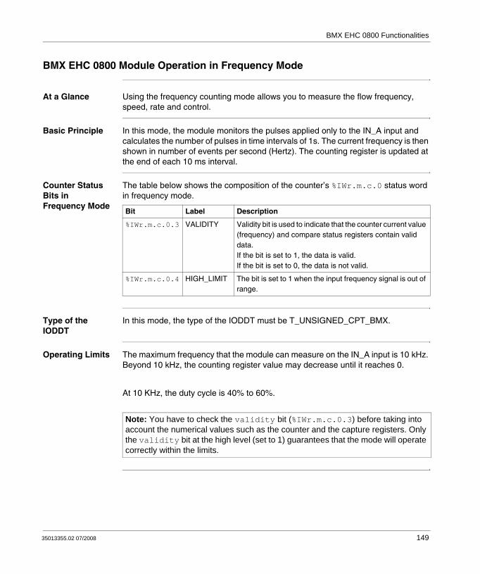
BMX EHC 0800 Functionalities
BMX EHC 0800 Module Operation in Frequency Mode
At a Glance Using the frequency counting mode allows you to measure the flow frequency, speed, rate and control.
Basic Principle In this mode, the module monitors the pulses applied only to the IN_A input and calculates the number of pulses in time intervals of 1s. The current frequency is then shown in number of events per second (Hertz). The counting register is updated at the end of each 10 ms interval.
Counter Status Bits in Frequency Mode
The table below shows the composition of the counter’s %IWr.m.c.0 status word in frequency mode.
Type of the IODDT
In this mode, the type of the IODDT must be T_UNSIGNED_CPT_BMX.
Operating Limits The maximum frequency that the module can measure on the IN_A input is 10 kHz. Beyond 10 kHz, the counting register value may decrease until it reaches 0.
At 10 KHz, the duty cycle is 40% to 60%.
Bit Label Description
%IWr.m.c.0.3 VALIDITY Validity bit is used to indicate that the counter current value (frequency) and compare status registers contain valid data.If the bit is set to 1, the data is valid.If the bit is set to 0, the data is not valid.
%IWr.m.c.0.4 HIGH_LIMIT The bit is set to 1 when the input frequency signal is out of range.
Note: You have to check the validity bit (%IWr.m.c.0.3) before taking into account the numerical values such as the counter and the capture registers. Only the validity bit at the high level (set to 1) guarantees that the mode will operate correctly within the limits.
35013355.02 07/2008 149
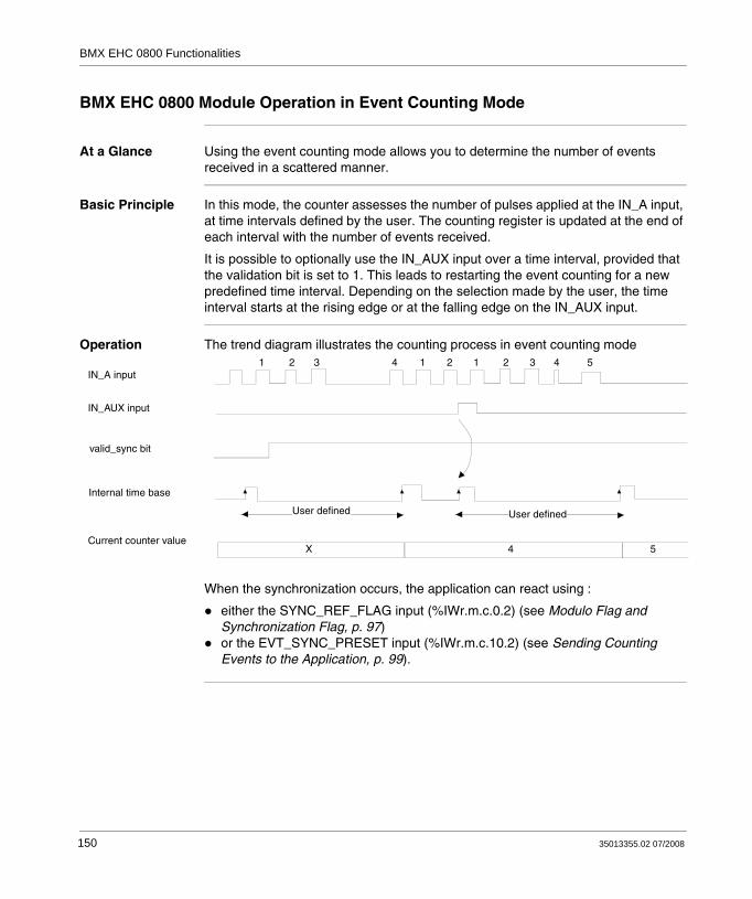
BMX EHC 0800 Functionalities
BMX EHC 0800 Module Operation in Event Counting Mode
At a Glance Using the event counting mode allows you to determine the number of events received in a scattered manner.
Basic Principle In this mode, the counter assesses the number of pulses applied at the IN_A input, at time intervals defined by the user. The counting register is updated at the end of each interval with the number of events received.
It is possible to optionally use the IN_AUX input over a time interval, provided that the validation bit is set to 1. This leads to restarting the event counting for a new predefined time interval. Depending on the selection made by the user, the time interval starts at the rising edge or at the falling edge on the IN_AUX input.
Operation The trend diagram illustrates the counting process in event counting mode
When the synchronization occurs, the application can react using :
either the SYNC_REF_FLAG input (%IWr.m.c.0.2) (see Modulo Flag and Synchronization Flag, p. 97)or the EVT_SYNC_PRESET input (%IWr.m.c.10.2) (see Sending Counting Events to the Application, p. 99).
IN_A input
IN_AUX input
valid_sync bit
Internal time base
Current counter value
User defined
1 2 3 4 1 2 1 2 3 4 5
X 4 5
User defined
150 35013355.02 07/2008

BMX EHC 0800 Functionalities
Counter Status Bits in Event Counting Mode
The table below shows the composition of the counter’s %IWr.m.c.0 status word in event counting mode.
Type of the IODDT
In this mode, the type of the IODDT is T_UNSIGNED_CPT_BMX.
Operating Limits The module counts the pulses applied at the IN_A input every time the pulse is at least 50 μs (without debounce filter).
Pulses within 100 ms from synchronization are lost.
The synchronization of the counter must not be done more than one time per 25 ms.
Bit Label Description
%IWr.m.c.0.2 SYNC_REF_FLAG The bit is set to 1 when the internal time base has been synchronized.The bit is set to 0 when the sync_reset command is received (rising edge of the %Qr.m.c.8 bit).
%IWr.m.c.0.3 VALIDITY Validity bit is used to indicate that the counter current value (events number) and compare status registers contain valid data.If the bit is set to 1, the data is valid.If the bit is set to 0, the data is not valid.
%IWr.m.c.0.4 HIGH_LIMIT The bit is set to 1 when the number of received events exceeds the counter size.The bit is reset to 0 at the next period if the limit is not reached.
%IWr.m.c.0.5 LOW_LIMIT The bit is set to 1 when more than one synchronization is received within 25 ms period.The bit is reset to 0 at the next period if the limit is not reached.
Note: You have to check the validity bit (%IWr.m.c.0.3) before taking into account the numerical values such as the counter and the capture registers. Only the validity bit at the high level (set to 1) guarantees that the mode will operate correctly within the limits.
35013355.02 07/2008 151

BMX EHC 0800 Functionalities
BMX EHC 0800 Module Operation in One Shot Counter Mode
At a Glance Using the one shot counter mode allows you to quantify a group of parts.
Basic Principle In this mode, activating the synchronization function starts the counter which, starting from a value defined by the user in the adjust screen (preset value), decreases with every pulse applied to the IN_A input until it reaches the value 0. Downcounting is made possible when the enable function is activated. The counting register is thus updated every 5 ms.
Operation The trend diagram illustrates the one shot counter mode process:
In the trend diagram above, we can see that the counter starts downcounting at the IN_AUX input’s rising edge. The counter loads the value defined by the user and decrements the counting register with every pulse applied to the IN_A input. When the register is set to 0, the counter awaits a new signal from the IN_AUX input. The IN_A input pulses have no effect on the register value as long as the counter is set to 0.
0
IN_A input (pulses)
IN_AUX input
valid_syncbit
force_enablebit
Counter value
User-defined value (preset value)
Operation of the counter
152 35013355.02 07/2008
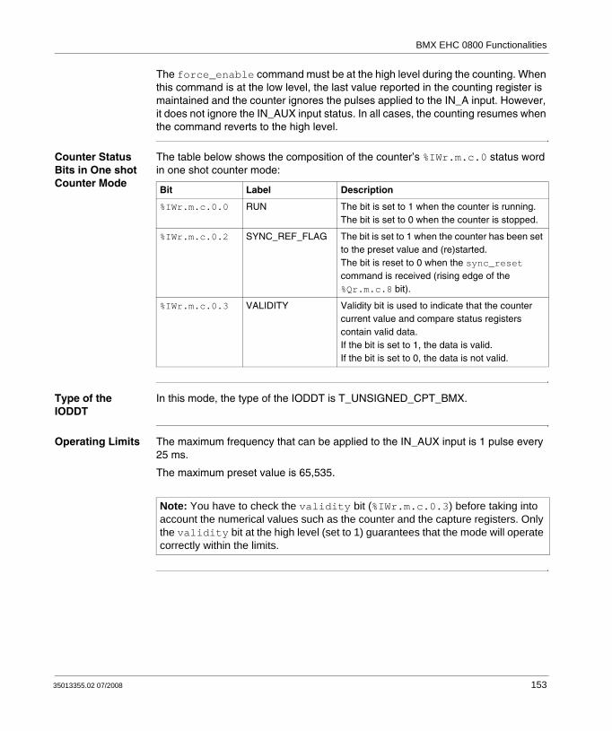
BMX EHC 0800 Functionalities
The force_enable command must be at the high level during the counting. When this command is at the low level, the last value reported in the counting register is maintained and the counter ignores the pulses applied to the IN_A input. However, it does not ignore the IN_AUX input status. In all cases, the counting resumes when the command reverts to the high level.
Counter Status Bits in One shot Counter Mode
The table below shows the composition of the counter’s %IWr.m.c.0 status word in one shot counter mode:
Type of the IODDT
In this mode, the type of the IODDT is T_UNSIGNED_CPT_BMX.
Operating Limits The maximum frequency that can be applied to the IN_AUX input is 1 pulse every 25 ms.
The maximum preset value is 65,535.
Bit Label Description
%IWr.m.c.0.0 RUN The bit is set to 1 when the counter is running.The bit is set to 0 when the counter is stopped.
%IWr.m.c.0.2 SYNC_REF_FLAG The bit is set to 1 when the counter has been set to the preset value and (re)started.The bit is reset to 0 when the sync_reset command is received (rising edge of the %Qr.m.c.8 bit).
%IWr.m.c.0.3 VALIDITY Validity bit is used to indicate that the counter current value and compare status registers contain valid data.If the bit is set to 1, the data is valid.If the bit is set to 0, the data is not valid.
Note: You have to check the validity bit (%IWr.m.c.0.3) before taking into account the numerical values such as the counter and the capture registers. Only the validity bit at the high level (set to 1) guarantees that the mode will operate correctly within the limits.
35013355.02 07/2008 153

BMX EHC 0800 Functionalities
BMX EHC 0800 Module Operation in Modulo Loop Counter Mode
At a Glance The use of the modulo loop counter mode is recommended for packaging and labeling applications for which actions are repeated for series of moving objects.
Basic Principle The counter increases with every pulse applied to the IN_A input until it reaches the modulo value -1, the modulo value being defined by the user. At the following pulse, the counter is reset to 0 and the counting resumes.
In the modulo loop counter mode, the counter must be synchronized at least one time to operate. The current counter value is cleared each time the synchronization occurs.
The current counter value can be recorded into the capture0 register (see Capture Function, p. 143) when the condition of synchronization occurs (see Synchroni-zation Function, p. 139).
The modulo value defined by the user is contained in the modulo_value word (%MDr.m.c.4). The user may change this value by specifying the value of this word:
In the adjust screenIn the application, using the WRITE_PARAM(IODDT_VAR1) Function. IODDT_VAR1 is of the type T_UNSIGNED_CPT_BMX.
The force_enable command must be at the high level during the counting. When this command is at the low level, the last value reported in the counting register is maintained and the counter ignores the pulses applied to the IN_A input. However, it does not ignore the IN_AUX input status. In all cases, the counting resumes when the command reverts to the high level.
In this mode, the counting register is updated at 5 ms intervals.
Unlike for the BMX EHC 0200 module, there is no downcounting.
154 35013355.02 07/2008

BMX EHC 0800 Functionalities
Operation The trend diagram below illustrates the modulo counting process:
Counter Status Bits in Modulo Loop Counter Mode
The table below shows the composition of the counter’s %IWr.m.c.0 status word in modulo loop counter mode:
IN_A input (pulses)
IN_AUX input
valid_sync bit
force_enablebit
Counter value
Modulo value
Capture value X1 X2 X3
X3
X1
X2
0Time
Bit Label Description
%IWr.m.c.0.1 MODULO_FLAG The bit is set to 1 when the counter rollovers the modulo and is .The bit is reset to 0 when the command MODULO_RESET (%Qr.m.c.9) is received (rising edge of the MODULO_RESET bit).
%IWr.m.c.0.2 SYNC_REF_FLAG The bit is set to 1 when the counter have been set to 0 and (re)started.The bit is reset to 0 when the command SYNC_RESET (%Qr.m.c.8) is received (rising edge of the SYNC_RESET bit).
%IWr.m.c.0.3 VALIDITY Validity bit is used to indicate that the counter current value and compare status registers contain valid data.If the bit is set to 1, the data is valid.If the bit is set to 0, the data is not valid.
35013355.02 07/2008 155
BMX EHC 0800 Functionalities
Type of the IODDT
In this mode, the type of the IODDT must be T_UNSIGNED_CPT_BMX.
Operating Limits The maximum frequency applied to the IN_A input is 10 kHz.
The shortest pulse applied to the IN_AUX input varies according to the level of filtering selected.
The maximum frequency that can be applied to the IN_AUX input is 1 pulse every 5 ms.
The maximum frequency for the modulo event is once every 5 ms.
The minimum acceptable modulo value varies according to the frequency at the IN_A input. E.g.: for a frequency of 10 kHz applied to the IN_A input, the modulo must be greater than 50.
The maximum modulo value is 65,535.
Note: When the modulo value is configured to 0, it is possible to count up to 65,536.
Note: You have to check the validity bit (%IWr.m.c.0.3) before taking into account the numerical values such as the counter and the capture registers. Only the validity bit at the high level (set to 1) guarantees that the mode will operate correctly within the limits.
156 35013355.02 07/2008

BMX EHC 0800 Functionalities
BMX EHC 0800 Module Operation in Upcounting and Downcounting Mode
At a Glance Using the upcounting and downcounting mode allows for an accumulation, upcounting or downcounting operation on a single input.
Basic Principle In this mode, the counting starts with the force_sync software command. On the rising edge, the counting register is updated with the preset value predefined by the user. The preset value is contained in the preset_value word (%MDr.m.c.6). The user may change this value by specifying the value of this word:
In the adjust screenIn the application, using the WRITE_PARAM(IODDT_VAR1) Function. IODDT_VAR1 is of the type T_SIGNED_CPT_BMX.
The following processing occurs at each pulse applied to the IN_A input:
Pulse counting if the IN_AUX input is highPulse downcounting if the IN_AUX input is low
The force_enable software command must be at the high level during the counting. When this command is at the low level, the last value reported in the counting register is maintained and the counter ignores the pulses applied to the IN_A input. The counting resumes when the command reverts to the high level.
Counting values vary between –32,768 and +32,767.
35013355.02 07/2008 157

BMX EHC 0800 Functionalities
Operation The trend diagram below illustrates the modulo up & down counting mode process: IN_A input (pulses)
IN_AUX input
force_enablebit
Preset value
Counter value
- 32K
0
force_sync bit
+ 32K
158 35013355.02 07/2008
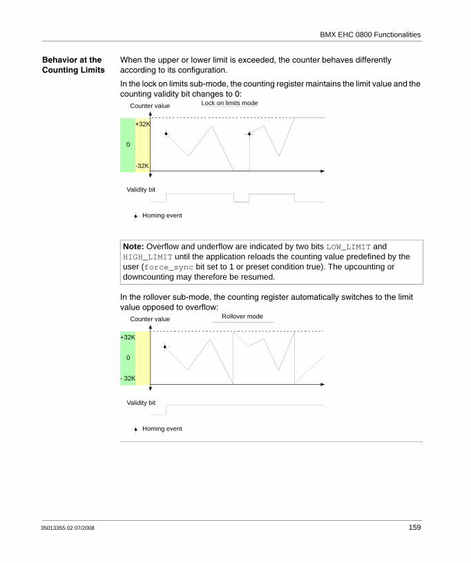
BMX EHC 0800 Functionalities
Behavior at the Counting Limits
When the upper or lower limit is exceeded, the counter behaves differently according to its configuration.
In the lock on limits sub-mode, the counting register maintains the limit value and the counting validity bit changes to 0:
In the rollover sub-mode, the counting register automatically switches to the limit value opposed to overflow:
Note: Overflow and underflow are indicated by two bits LOW_LIMIT and HIGH_LIMIT until the application reloads the counting value predefined by the user (force_sync bit set to 1 or preset condition true). The upcounting or downcounting may therefore be resumed.
Homing event
Counter value Lock on limits mode
Validity bit
-32K
0
+32K
Homing event
Counter value Rollover mode
Validity bit
0
+32K
- 32K
35013355.02 07/2008 159
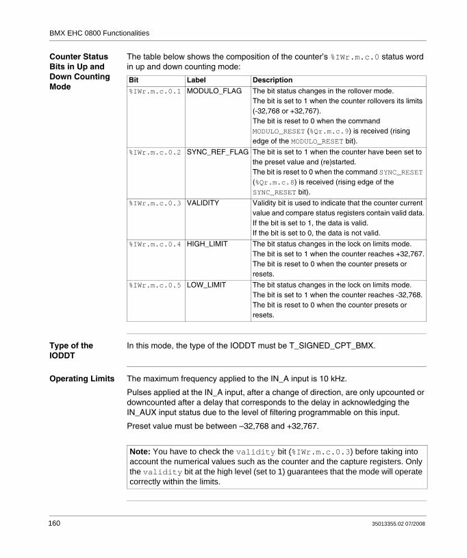
BMX EHC 0800 Functionalities
Counter Status Bits in Up and Down Counting Mode
The table below shows the composition of the counter’s %IWr.m.c.0 status word in up and down counting mode:
Type of the IODDT
In this mode, the type of the IODDT must be T_SIGNED_CPT_BMX.
Operating Limits The maximum frequency applied to the IN_A input is 10 kHz.
Pulses applied at the IN_A input, after a change of direction, are only upcounted or downcounted after a delay that corresponds to the delay in acknowledging the IN_AUX input status due to the level of filtering programmable on this input.
Preset value must be between –32,768 and +32,767.
Bit Label Description
%IWr.m.c.0.1 MODULO_FLAG The bit status changes in the rollover mode.The bit is set to 1 when the counter rollovers its limits (-32,768 or +32,767).The bit is reset to 0 when the command MODULO_RESET (%Qr.m.c.9) is received (rising edge of the MODULO_RESET bit).
%IWr.m.c.0.2 SYNC_REF_FLAG The bit is set to 1 when the counter have been set to the preset value and (re)started.The bit is reset to 0 when the command SYNC_RESET (%Qr.m.c.8) is received (rising edge of the SYNC_RESET bit).
%IWr.m.c.0.3 VALIDITY Validity bit is used to indicate that the counter current value and compare status registers contain valid data.If the bit is set to 1, the data is valid.If the bit is set to 0, the data is not valid.
%IWr.m.c.0.4 HIGH_LIMIT The bit status changes in the lock on limits mode.The bit is set to 1 when the counter reaches +32,767.The bit is reset to 0 when the counter presets or resets.
%IWr.m.c.0.5 LOW_LIMIT The bit status changes in the lock on limits mode.The bit is set to 1 when the counter reaches -32,768.The bit is reset to 0 when the counter presets or resets.
Note: You have to check the validity bit (%IWr.m.c.0.3) before taking into account the numerical values such as the counter and the capture registers. Only the validity bit at the high level (set to 1) guarantees that the mode will operate correctly within the limits.
160 35013355.02 07/2008
BMX EHC 0800 Functionalities
BMX EHC 0800 Module Operation in Dual Phase Counting Mode
At a Glance The dual phase counting mode is available for channels 0, 2, 4, and 6 (channels 1, 3, 5 and 7 become inactive). It behaves like the up and down counting mode and uses up to three physical inputs. It enables simultaneous upcounting and downcounting.
Basic Principle In the Dual phase counting mode, the counter must be synchronized at least one time to operate. The current counter value is preset each time the synchronization occurs. The current counter value can be recorded into the capture0 register when the condition of synchronization occurs.
For further information, you may see the synchronization function (see Synchroni-zation Function, p. 139) and the capture function (see Capture Function, p. 143).
The force_enable software command must be at the high level during the counting. When this command is at the low level, the last value reported in the counting register is maintained and the counter ignores the pulses applied to the IN_A and IN_B inputs. The counting resumes when the command reverts to the high level.
Counting values vary between the limits -2,147,483,648 and +2,147,483,647 (31-bit word and one sign bit).
The preset value is predefined by the user and is contained in the preset_value word (%MDr.m.c.6). The user may change this value by specifying the value of this word:
In the adjust screenIn the application, using the WRITE_PARAM(IODDT_VAR1) Function. IODDT_VAR1 is of the type T_Signed_CPT_BMX.
35013355.02 07/2008 161

BMX EHC 0800 Functionalities
Counting Configurations
In this mode, the user may select one of the following counting configurations:
A = Up, B = Down (default configuration)A = Impulse, B = DirectionNormal Quadrature X1Normal Quadrature X2Normal Quadrature X4Reverse Quadrature X1Reverse Quadrature X2Reverse Quadrature X4.
The following table shows the upcounting and downcounting principle according to the selected configuration:
Selected configuration Upcounting condition Downcounting condition
A = Up, B = Down Rising edge at the IN_A input. Rising edge at the IN_B input.
A = Impulse, B = Direction Rising edge at the IN_A input and high state at the IN_B input.
Rising edge at the IN_A input and low state at the IN_B input.
Normal Quadrature X1 Rising edge at the IN_A input and low state at the IN_B input.
Falling edge at the IN_A input and low state at the IN_B input.
Normal Quadrature X2 Rising edge at the IN_A input and low state at the IN_B input.Falling edge at the IN_A input and high state at the IN_B input.
Falling edge at the IN_A input and low state at the IN_B input.Rising edge at the IN_A input and high level at the IN_B input.
Normal Quadrature X4 Rising edge at the IN_A input and low state at the IN_B input.High state at the IN_A input and rising edge at the IN_B input.Falling edge at the IN_A input and high state at the IN_B input.Low state at the IN_A input and falling edge at the IN_B input.
Falling edge at the IN_A input and low state at the IN_B input.Low state at the IN_A input and rising edge at the IN_B input.Rising edge at the IN_A input and high level at the IN_B input.High state at the IN_A input and falling edge at the IN_B input.
Reverse Quadrature X1 Falling edge at the IN_A input and low state at the IN_B input.
Rising edge at the IN_A input and low state at the IN_B input.
Reverse Quadrature X2 Falling edge at the IN_A input and low state at the IN_B input.Rising edge at the IN_A input and high level at the IN_B input.
Rising edge at the IN_A input and low state at the IN_B input.Falling edge at the IN_A input and high state at the IN_B input.
162 35013355.02 07/2008
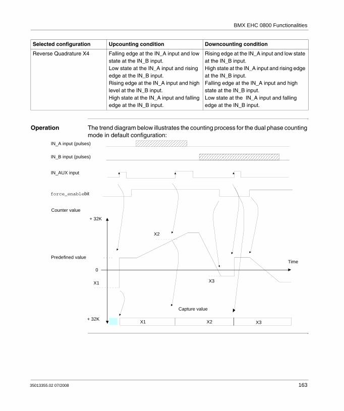
BMX EHC 0800 Functionalities
Operation The trend diagram below illustrates the counting process for the dual phase counting mode in default configuration:
Reverse Quadrature X4 Falling edge at the IN_A input and low state at the IN_B input.Low state at the IN_A input and rising edge at the IN_B input.Rising edge at the IN_A input and high level at the IN_B input.High state at the IN_A input and falling edge at the IN_B input.
Rising edge at the IN_A input and low state at the IN_B input.High state at the IN_A input and rising edge at the IN_B input.Falling edge at the IN_A input and high state at the IN_B input.Low state at the IN_A input and falling edge at the IN_B input.
Selected configuration Upcounting condition Downcounting condition
IN_A input (pulses)
IN_AUX input
Predefined value
Capture value
+ 32K
0
force_enablebit
+ 32K
IN_B input (pulses)
Counter value
X1
X3X1
X2
Time
X2 X3
35013355.02 07/2008 163

BMX EHC 0800 Functionalities
Slack Delete In the free large counter mode, the counter may apply a hysteresis if the rotation is inverted. The hysteresis parameter configured with the adjust screen defines the number of points that are not acknowledged by the counter during the rotation inversion. This aims to take into account the slack between the encoder/motor axis and the mechanical axis (e.g. an encoder measuring the position of a mat).
This behavior is described in the following figure:
The value defined by the user as the Hysteresis (slack) value is contained in the %MWr.m.c.9 word. The user may change this value by specifying the value of this word (this value is from 0 to 255):
In the adjust screenIn the application by using the WRITE_PARAM(IODDT_VAR1) Function. IODDT_VAR1 is of the type T_Signed_CPT_BMX.
Encoder forward motion
Counter value
Hysteresis Hysteresis
Mechanical forward motion
Encoder return motion
Mechanical return motion
Encoder forward motion
Mechanical forward motion
164 35013355.02 07/2008

BMX EHC 0800 Functionalities
Behavior at the Counting Limits
When the upper or lower limit is exceeded, the counter behaves differently according to its configuration.
In the lock on limits default configuration, the counting register maintains the limit value and the counting validity bit changes to 0 until the next preset condition occurs:
In the rollover configuration, the counting register automatically switches to the limit value opposed to overflow
Note: Overflow and underflow are indicated by two bits LOW_LIMIT and HIGH_LIMIT until the application reloads the counting value predefined by the user (force_ref bit set to 1 or preset condition true). The upcounting or downcounting may therefore resume.
Homing event
Counter value Lock on limits mode
Validity bit
- 2M
0
+ 2M
Homing event
Counter value Rollover mode
Validity bit
0
+ 2M
- 2M
35013355.02 07/2008 165

BMX EHC 0800 Functionalities
Counter Status Bits in Dual Phase Counting Mode
The table below shows the composition of the counter’s %IWr.m.c.0 status word in dual phase counting mode:
Type of the IODDT
In this mode, the type of the IODDT must be T_SIGNED_CPT_BMX.
Operating Limits The maximum frequency applied to the IN_A and IN_B inputs is 10 kHz.
The shortest pulse applied to the IN_AUX input is defined according to the level of filtering applied to the input.
The maximum loading frequency for the value predefined by the user is once every 25 ms.
Bit Label Description
%IWr.m.c.0.1 MODULO_FLAG The bit status changes in the rollover mode.The bit is set to 1 when the counter rollovers its limits (-2,147,483,648 or +2,147,483,647).The bit is reset to 0 when the command MODULO_RESET (%Qr.m.c.9) is received (rising edge of the MODULO_RESET bit).
%IWr.m.c.0.2 SYNC_REF_FLAG The bit is set to 1 when the counter have been set to the preset value and (re)started.The bit is reset to 0 when the command SYNC_RESET (%Qr.m.c.8) is received (rising edge of the SYNC_RESET bit).
%IWr.m.c.0.3 VALIDITY Validity bit is used to indicate that the counter current value and compare status registers contain valid data.If the bit is set to 1, the data is valid.If the bit is set to 0, the data is not valid.
%IWr.m.c.0.4 HIGH_LIMIT The bit status changes in the lock on limits mode.The bit is set to 1 when the counter reaches +2,147,483,647.The bit is reset to 0 when the counter presets.
%IWr.m.c.0.5 LOW_LIMIT The bit status changes in the lock on limits mode.The bit is set to 1 when the counter reaches -2,147,483,648.The bit is reset to 0 when the counter presets.
Note: You have to check the validity bit (%IWr.m.c.0.3) before taking into account the numerical values such as the counter and the capture registers. Only the validity bit at the high level (set to 1) guarantees that the mode will operate correctly within the limits.
166 35013355.02 07/2008
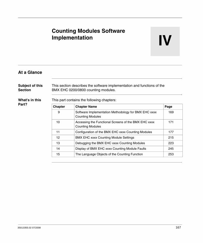
35013355.02 07/2008
IV
Counting Modules Software ImplementationAt a Glance
Subject of this Section
This section describes the software implementation and functions of the BMX EHC 0200/0800 counting modules.
What's in this Part?
This part contains the following chapters:
Chapter Chapter Name Page
9 Software Implementation Methodology for BMX EHC xxxx Counting Modules
169
10 Accessing the Functional Screens of the BMX EHC xxxx Counting Modules
171
11 Configuration of the BMX EHC xxxx Counting Modules 177
12 BMX EHC xxxx Counting Module Settings 215
13 Debugging the BMX EHC xxxx Counting Modules 223
14 Display of BMX EHC xxxx Counting Module Faults 245
15 The Language Objects of the Counting Function 253
167

Counting Modules Software Implementation
168 35013355.02 07/2008

35013355.02 07/2008
9
Software Implementation Methodology for BMX EHC xxxx Counting ModulesInstallation Methodology
At a Glance The software installation of the counting modules is carried out from the various Unity Pro editors:
in offline mode,in online mode.
The following order of installation phases is recommended but it is possible to change the order of certain phases (for example, starting with the configuration phase).
169

Software Implementation Methodology for Counting Modules
Installation Phases
The following table shows the different installation phases:
Phase Description Mode
Declaration of variables
Declaration of IODDT-type variables for the application-specific modules and variables of the project.
Offline(1)
Programming Project programming. Offline(1)
Configuration Declaration of modules. Offline
Module channel configuration
Entering the configuration parametersNote: All the parameters are configurable online except the event parameter.
Offline(1)
Association Association of IODDTs with the channels configured (variable editor)
Offline(1)
Build Project generation (analysis and editing of links) Offline
Transfer Transfer project to PLC Online
Adjustment/Debugging
Debug project from debug screens, animation tables
Online
Debugging the program and adjustment parameters
Documentation Building documentation file and printing miscellaneous information relating to the project
Online(1)
Operation/Diagnostic
Displaying miscellaneous information necessary for supervisory control of the project
Online
Diagnostics of project and modules
Key:
(1) These various phases can also be performed in online mode
170 35013355.02 07/2008

35013355.02 07/2008
10
Accessing the Functional Screens of the BMX EHC xxxx Counting ModulesAt a Glance
Subject of this Section
This section describes the various functional screens of the BMX EHC •••• counting modules to which the user has access.
What's in this Chapter?
This chapter contains the following topics:
Topic Page
Accessing the Functional Screens of the BMX EHC xxxx Counting Modules 172
Description of the Counting Module Screens 174
171
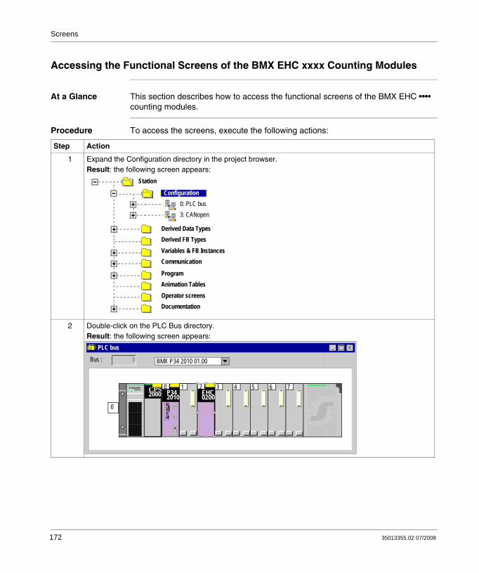
Screens
Accessing the Functional Screens of the BMX EHC xxxx Counting Modules
At a Glance This section describes how to access the functional screens of the BMX EHC •••• counting modules.
Procedure To access the screens, execute the following actions:
Step Action
1 Expand the Configuration directory in the project browser.Result: the following screen appears:
2 Double-click on the PLC Bus directory.Result: the following screen appears:
Derived Data Types
Station
Derived FB TypesVariables & FB InstancesCommunication
ProgramAnimation TablesOperator screensDocumentation
Configuration0: PLC bus3: CANopen
Bus : 0 BMX P34 2010 01.00
PLC bus
765432CPS2000 EHC
020010
P342010Sdca
SchneiderElectricS
0
172 35013355.02 07/2008
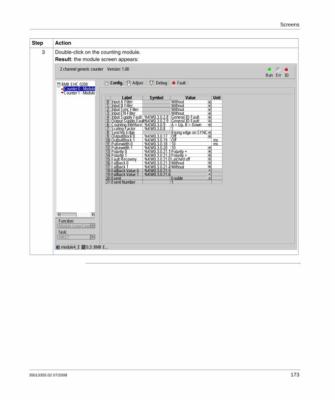
Screens
3 Double-click on the counting module.Result: the module screen appears:
Step Action
2 channel generic counter Version: 1.00Run Err IO
Config. FaultDebugAdjust
Function:
Task:Modulo Loop-Coun
BMX EHC 0200
Counter 1 - Modulo Counter 0 - Modulo
MAST
module4_E 0.3: BMX E...
Input A Filter Without0Input B Filter Without1Input Sync Filter Without2Input EN Filter Without3Input Supply Fault %KW0.3.0.2.8 General IO Fault4Output Supply Fault%KW0.3.0.2.9 General IO Fault5Counting Interface %KW0.3.0.9 A = Up, B = Down6Scaling Factor %KW0.3.0.8 17Synchro Edge Rising edge on SYNC8OutputBlock 0 %KW0.3.0.17 Off9OutputBlock 1 %KW0.3.0.19 Off ms10Pulsewidth 0 %KW0.3.0.18 10 ms11Pulsewidth 1 %KW0.3.0.20 1012Polarity 0 %KW0.3.0.21.1 Polarity +13Polarity 1 %KW0.3.0.21.2 Polarity +14Fault Recovery %KW0.3.0.21.0 Latched off15Fallback 0 %KW0.3.0.21.3 Without16Fallback 1 %KW0.3.0.21.4 Without17Fallback Value 0 %KW0.3.0.21.518Fallback Value 1 %KW0.3.0.21.619Event Enable20Event Number 121
Label Symbol Value Unit
35013355.02 07/2008 173
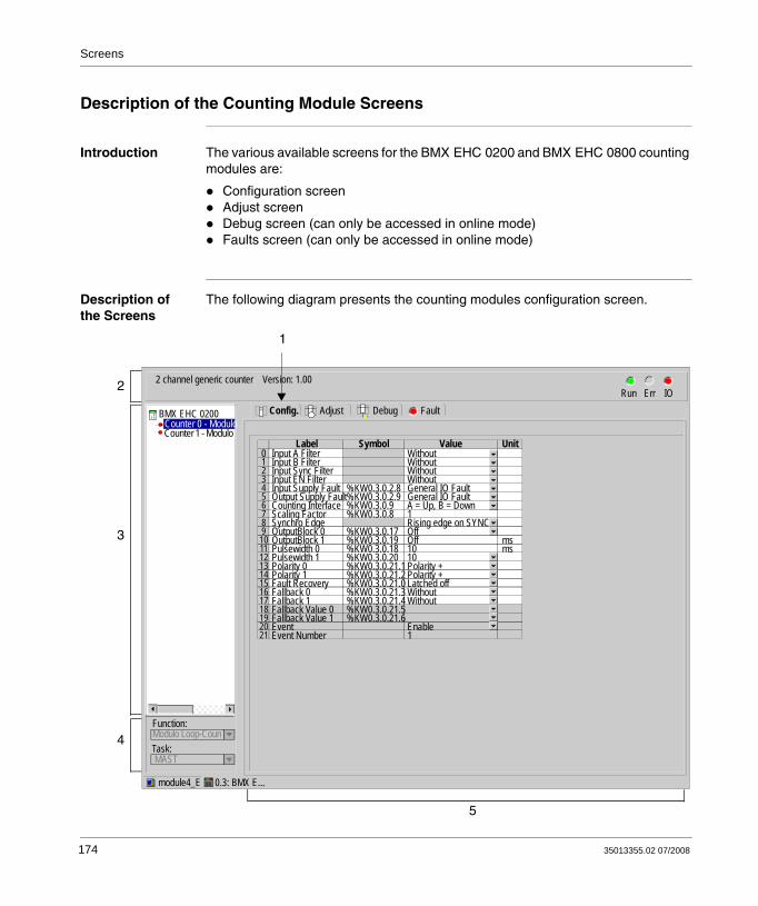
Screens
Description of the Counting Module Screens
Introduction The various available screens for the BMX EHC 0200 and BMX EHC 0800 counting modules are:
Configuration screenAdjust screenDebug screen (can only be accessed in online mode)Faults screen (can only be accessed in online mode)
Description of the Screens
The following diagram presents the counting modules configuration screen.
2 channel generic counter Version: 1.00Run Err IO
Config. FaultDebugAdjust
Function:
Task:Modulo Loop-Coun
BMX EHC 0200
Counter 1 - Modulo Counter 0 - Modulo
MAST
module4_E 0.3: BMX E...
Input A Filter Without0Input B Filter Without1Input Sync Filter Without2Input EN Filter Without3Input Supply Fault %KW0.3.0.2.8 General IO Fault4Output Supply Fault%KW0.3.0.2.9 General IO Fault5Counting Interface %KW0.3.0.9 A = Up, B = Down6Scaling Factor %KW0.3.0.8 17Synchro Edge Rising edge on SYNC8OutputBlock 0 %KW0.3.0.17 Off9OutputBlock 1 %KW0.3.0.19 Off ms10Pulsewidth 0 %KW0.3.0.18 10 ms11Pulsewidth 1 %KW0.3.0.20 1012Polarity 0 %KW0.3.0.21.1 Polarity +13Polarity 1 %KW0.3.0.21.2 Polarity +14Fault Recovery %KW0.3.0.21.0 Latched off15Fallback 0 %KW0.3.0.21.3 Without16Fallback 1 %KW0.3.0.21.4 Without17Fallback Value 0 %KW0.3.0.21.518Fallback Value 1 %KW0.3.0.21.619Event Enable20Event Number 121
Label Symbol Value Unit
1
2
3
4
5
174 35013355.02 07/2008

Screens
The following table presents the parts of the various screens.
Number Element Function
1 Tabs The tab in the foreground indicates the mode in progress (Configuration in this example). Every mode can be selected using the respective tab. The available modes are:
ConfigurationAdjustDebug (which can only be accessed in online mode)Faults (which can only be accessed in online mode)
2 Module area Provides an abbreviation as a reminder of the module and module status in online mode (LEDs).
3 Channel area Is used:By clicking on the reference number, to display the tabs:
Description which gives the characteristics of the device.I/O Objects which is used to presymbolize the input/output objects.Faults which shows the device faults (in online mode).
To select a channel.To display the Symbol, name of the channel defined by the user (using the variable editor).
4 General parameters area
Allows you to select the counting function and the task associated with the channel:
Function: counting function among those available for the modules involved. Depending on this choice, the headings of the configuration area may differ. By default, no function is configured.Task: defines the MAST or FAST task through which the channel's implicit exchange objects will be exchanged.
These choices are only possible in offline mode.
5 Parameters in progress area
This area has various functionalities which depend upon the current mode:
Configuration: is used to configure the channel parameters.Adjust: consists of various sections to be completed (parameter values), displayed according to the choice of counting function.Debug: displays the status of the inputs and outputs, as well as the various parameters of the current counting function.Faults: displays the faults that have occurred on the counting channels.
35013355.02 07/2008 175

Screens
176 35013355.02 07/2008
35013355.02 07/2008
11
Configuration of the BMX EHC xxxx Counting ModulesAt a Glance
Subject of this Section
This section deals with the configuration of the BMX EHC•••• counting modules. This configuration can be accessed from the Configuration tab on the functional screens of BMX EHC•••• (see Description of the Counting Module Screens, p. 174) modules.
What's in this Chapter?
This chapter contains the following sections:
Section Topic Page
11.1 Configuration Screen for BMX EHC xxxx Counting Modules 178
11.2 Configuration of Modes for the BMX EHC 0200 Module 180
11.3 Configuration of Modes for the BMX EHC 0800 Module 205
177

Configuration of the Counting Modules
11.1 Configuration Screen for BMX EHC xxxx Counting Modules
Configuration Screen for BMX EHC xxxx Counting Modules
At a Glance This section presents the configuration screen for BMX EHC •••• counting modules.
Illustration The figure below presents the configuration screen for the BMX EHC 0200 module in modulo loop counter mode:
2 channel generic counter Version : 1.00Run Err IO
Config. FaultDebugAdjust
Function:
Task:Modulo Loop-
BMX EHC 0200
Counter 1 - Modulo LCounter 0 - Modulo L
MAST
module4_E 0.3: BMX E...
Input A Filter Without0Input B Filter Without1Input Sync Filter Without2Input EN Filter Without3Input Supply Fault %KW0.3.0.2.8 General IO Fault4Output Supply Fault %KW0.3.0.2.9 General IO Fault5Counting Interface %KW0.3.0.9 A = Up, B = Down6Scaling Factor %KW0.3.0.8 17Synchro Edge Rising edge on SYNC8OutputBlock 0 %KW0.3.0.17 Off9OutputBlock 1 %KW0.3.0.19 Off ms10Pulsewidth 0 %KW0.3.0.18 10 ms11Pulsewidth 1 %KW0.3.0.20 1012Polarity 0 %KW0.3.0.21.1 Polarity +13Polarity 1 %KW0.3.0.21.2 Polarity +14Fault Recovery %KW0.3.0.21.0 Latched off15Fallback 0 %KW0.3.0.21.3 Without16Fallback 1 %KW0.3.0.21.4 Without17Fallback Value 0 %KW0.3.0.21.518Fallback Value 1 %KW0.3.0.21.619Event Enable20Event Number 121
Label Symbol Value Unit
1 2 3 4 5
178 35013355.02 07/2008

Configuration of the Counting Modules
Description of the Screen
The following table presents the various parts of the above screen:
Number Element Function
1 Tab The tab in the foreground indicates the current mode. The current mode is therefore the configuration mode in this example.
2 Label field This field contains the name of each variable that may be configured. This field may not be modified.
3 Symbol field This field contains the address of the variable in the application. This field may not be modified.
4 Value field If this field has a downward pointing arrow, you can select the value of each variable from various possible values in this field. The various values can be accessed by clicking on the arrow. A drop-down menu containing all the possible values is displayed and the user may then select the required value of the variable.
5 Unit field This field contains the unit of each variable that may be configured. This field may not be modified.
35013355.02 07/2008 179

Configuration of the Counting Modules
11.2 Configuration of Modes for the BMX EHC 0200 Module
At a Glance
Subject of this Section
This section deals with the configuration of the modes of the BMX EHC 0200 counting modules.
What's in this Section?
This section contains the following topics:
Topic Page
Frequency Mode Configuration 181
Event Counting Mode Configuration 183
Period Measuring Mode Configuration 187
Ratio Mode Configuration 190
One Shot Counter Mode Configuration 193
Modulo Loop Counter Mode Configuration 196
Free Large Counter Mode Configuration 199
Pulse Width Modulation Mode Configuration 203
180 35013355.02 07/2008

Configuration of the Counting Modules
Frequency Mode Configuration
At a Glance The configuration of a counting module is stored in the configuration constants (%KW).
The parameters r,m and c shown in the following tables represent the topologic addressing of the module. Each parameter had the following signification:
r: represents the rack number,m:represents the position of the module on the rack,c: represents the channel number.
Configuration Objects
The table below presents the frequency mode configurable elements.
Number Address in the configuration
Configurable values
Counting mode %KWr.m.c.2(least significant byte)
Frequency mode. The value of the least significant byte of this word is 1.
IN_A input filter %KWr.m.c.3(least significant byte)
The least significant byte can take the following values:
0: none,1: low,2: medium,3: high.
Input power supply fault
%KWr.m.c.2.8 General input/output fault (bit set to 0)Local (bit set to 1)
Scale factor %KWr.m.c.6(least significant byte)
Edit (value in the range 1...255)
Output block 0 %KWr.m.c.17 This word can take the following values:0: off,1: low counter,2: counter in a window,3: High counter,4: pulse = less than the lower threshold (LT),5: pulse = greater than the lower threshold (LT),6: pulse = less than the upper threshold (UT),7: pulse = greater than the upper threshold (UT).
35013355.02 07/2008 181

Configuration of the Counting Modules
Output block 1 %KWr.m.c.19 This word can take the following values:0: off,1: low counter,2: counter in a window,3: High counter,4: pulse = less than the lower threshold (LT),5: pulse = greater than the lower threshold (LT),6: pulse = less than the upper threshold (UT),7: pulse = greater than the upper threshold (UT).
Polarity 0 %KWr.m.c.21.1 Polarity + (bit set to 0)Polarity - (bit set to 1)
Polarity 1 %KWr.m.c.21.2 Polarity + (bit set to 0)Polarity - (bit set to 1)
Fault recovery %KWr.m.c.21.0 Automatic reaction (bit set to 1)Activated (bit set to 0)
Fallback 0 %KWr.m.c.21.3 None (bit set to 0)With (bit set to 1)
Fallback 1 %KWr.m.c.21.4 None (bit set to 0)With (bit set to 1)
Fallback value 0 %KWr.m.c.21.5 0 (bit set to 0)1 (bit set to 1)
Fallback value 1 %KWr.m.c.21.6 0 (bit set to 0)1 (bit set to 1)
Output power supply fault
%KWr.m.c.2.9 General input/output fault (bit set to 0)Offline (bit set to 1)
Pulse width 0 %KWr.m.c.18 Edit (value in the range 1...65535)
Pulse width 1 %KWr.m.c.20 Edit (value in the range 1...65535)
EventEvent number
%KWr.m.c.0 Activated (if activated is selected, the entered event number is coded on the most significant byte of this word)Deactivated (all bits of the most significant byte of this word are set to 1)
Number Address in the configuration
Configurable values
182 35013355.02 07/2008

Configuration of the Counting Modules
Event Counting Mode Configuration
At a Glance The configuration of a counting module is stored in the configuration constants (%KW).
The parameters r,m and c shown in the following tables represent the topologic addressing of the module. Each parameter had the following signification:
r: represents the rack number,m:represents the position of the module on the rack,c: represents the channel number.
Configuration Objects
The table below presents the event counting mode configurable elements
Number Address in the configuration
Configurable values
Counting mode %KWr.m.c.2(least significant byte)
Event counting mode. The value of the least significant byte of this word is 2.
IN_A input filter %KWr.m.c.3(least significant byte)
The least significant byte can take the following values:
0: none,1: low,2: medium,3: high.
IN_SYNC input filter %KWr.m.c.4(least significant byte)
The least significant byte can take the following values:
0: none,1: low,2: medium,3: high.
Input power supply fault
%KWr.m.c.2.8 General input/output fault (bit set to 0)Local (bit set to 1)
Synchronization edge %KWr.m.c.10.8 Rising edge at IN_SYNC (bit set to 0)Falling edge at IN_SYNC (bit set to 1)
Time base %KWr.m.c.7 This word can take the following values:0: 0.1 s,1: 1 s,2: 10 s,3: 1 min
35013355.02 07/2008 183
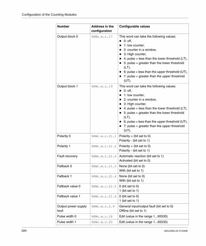
Configuration of the Counting Modules
Output block 0 %KWr.m.c.17 This word can take the following values:0: off,1: low counter,2: counter in a window,3: High counter,4: pulse = less than the lower threshold (LT),5: pulse = greater than the lower threshold (LT),6: pulse = less than the upper threshold (UT),7: pulse = greater than the upper threshold (UT).
Output block 1 %KWr.m.c.19 This word can take the following values:0: off,1: low counter,2: counter in a window,3: High counter,4: pulse = less than the lower threshold (LT),5: pulse = greater than the lower threshold (LT),6: pulse = less than the upper threshold (UT),7: pulse = greater than the upper threshold (UT).
Polarity 0 %KWr.m.c.21.1 Polarity + (bit set to 0)Polarity - (bit set to 1)
Polarity 1 %KWr.m.c.21.2 Polarity + (bit set to 0)Polarity - (bit set to 1)
Fault recovery %KWr.m.c.21.0 Automatic reaction (bit set to 1)Activated (bit set to 0)
Fallback 0 %KWr.m.c.21.3 None (bit set to 0)With (bit set to 1)
Fallback 1 %KWr.m.c.21.4 None (bit set to 0)With (bit set to 1)
Fallback value 0 %KWr.m.c.21.5 0 (bit set to 0)1 (bit set to 1)
Fallback value 1 %KWr.m.c.21.6 0 (bit set to 0)1 (bit set to 1)
Output power supply fault
%KWr.m.c.2.9 General input/output fault (bit set to 0)Offline (bit set to 1)
Pulse width 0 %KWr.m.c.18 Edit (value in the range 1...65535)
Pulse width 1 %KWr.m.c.20 Edit (value in the range 1...65535)
Number Address in the configuration
Configurable values
184 35013355.02 07/2008

Configuration of the Counting Modules
Output block 0 %KWr.m.c.17 This word can take the following values:0: off,1: low counter,2: counter in a window,3: High counter,4: pulse = less than the lower threshold (LT),5: pulse = greater than the lower threshold (LT),6: pulse = less than the upper threshold (UT),7: pulse = greater than the upper threshold (UT).
Output block 1 %KWr.m.c.19 This word can take the following values:0: off,1: low counter,2: counter in a window,3: High counter,4: pulse = less than the lower threshold (LT),5: pulse = greater than the lower threshold (LT),6: pulse = less than the upper threshold (UT),7: pulse = greater than the upper threshold (UT).
Polarity 0 %KWr.m.c.21.1 Polarity + (bit set to 0)Polarity - (bit set to 1)
Polarity 1 %KWr.m.c.21.2 Polarity + (bit set to 0)Polarity - (bit set to 1)
Fault recovery %KWr.m.c.21.0 Automatic reaction (bit set to 1)Activated (bit set to 0)
Fallback 0 %KWr.m.c.21.3 None (bit set to 0)With (bit set to 1)
Fallback 1 %KWr.m.c.21.4 None (bit set to 0)With (bit set to 1)
Fallback value 0 %KWr.m.c.21.5 0 (bit set to 0)1 (bit set to 1)
Fallback value 1 %KWr.m.c.21.6 0 (bit set to 0)1 (bit set to 1)
Output power supply fault
%KWr.m.c.2.9 General input/output fault (bit set to 0)Offline (bit set to 1)
Pulse width 0 %KWr.m.c.18 Edit (value in the range 1...65535)
Pulse width 1 %KWr.m.c.20 Edit (value in the range 1...65535)
Number Address in the configuration
Configurable values
35013355.02 07/2008 185

Configuration of the Counting Modules
EventEvent number
%KWr.m.c.0 Activated (if activated is selected, the entered event number is coded on the most significant byte of this word)Deactivated (all bits of the most significant byte of this word are set to 1)
Number Address in the configuration
Configurable values
186 35013355.02 07/2008

Configuration of the Counting Modules
Period Measuring Mode Configuration
At a Glance The configuration of a counting module is stored in the configuration constants (%KW).
The parameters r,m and c shown in the following tables represent the topologic addressing of the module. Each parameter had the following signification:
r: represents the rack number,m:represents the position of the module on the rack,c: represents the channel number.
Configuration Objects
The table below presents the period measuring mode configurable elements.
Number Address in the configuration
Configurable values
Counting mode %KWr.m.c.2(least significant byte)
Period measuring mode. The value of the least significant byte of this word is 3.
IN_A input filter %KWr.m.c.3(least significant byte)
The least significant byte can take the following values:
0: none,1: low,2: medium,3: high.
IN_SYNC input filter %KWr.m.c.4(least significant byte)
The least significant byte can take the following values:
0: none,1: low,2: medium,3: high.
Input power supply fault
%KWr.m.c.2.8 General input/output fault (bit set to 0)Local (bit set to 1)
Resolution %KWr.m.c.8(most significant byte)
The most significant byte can take the following values:
0: 1 μs,1: 100 μs,2: 1 ms.
35013355.02 07/2008 187

Configuration of the Counting Modules
Mode %KWr.m.c.8(least significant byte)
The least significant byte can take the following values:
0: From one edge to the same edge at input IN_A,1: From one edge to the opposite edge at input IN_A.
Time out %KDr.m.c.14 0... 1 073 741 823
Output block 0 %KWr.m.c.17 This word can take the following values:0: off,1: low counter,2: counter in a window,3: High counter,4: pulse = less than the lower threshold (LT),5: pulse = greater than the lower threshold (LT),6: pulse = less than the upper threshold (UT),7: pulse = greater than the upper threshold (UT).
Output block 1 %KWr.m.c.19 This word can take the following values:0: off,1: low counter,2: counter in a window,3: High counter,4: pulse = less than the lower threshold (LT),5: pulse = greater than the lower threshold (LT),6: pulse = less than the upper threshold (UT),7: pulse = greater than the upper threshold (UT).
Polarity 0 %KWr.m.c.21.1 Polarity + (bit set to 0)Polarity - (bit set to 1)
Polarity 1 %KWr.m.c.21.2 Polarity + (bit set to 0)Polarity - (bit set to 1)
Fault recovery %KWr.m.c.21.0 Automatic reaction (bit set to 1)Activated (bit set to 0)
Fallback 0 %KWr.m.c.21.3 None (bit set to 0)With (bit set to 1)
Number Address in the configuration
Configurable values
188 35013355.02 07/2008

Configuration of the Counting Modules
Fallback 1 %KWr.m.c.21.4 None (bit set to 0)With (bit set to 1)
Fallback value 0 %KWr.m.c.21.5 0 (bit set to 0)1 (bit set to 1)
Fallback value 1 %KWr.m.c.21.6 0 (bit set to 0)1 (bit set to 1)
Output power supply fault
%KWr.m.c.2.9 General input/output fault (bit set to 0)Offline (bit set to 1)
Pulse width 0 %KWr.m.c.18 Edit (value in the range 1...65535)
Pulse width 1 %KWr.m.c.20 Edit (value in the range 1...65535)
EventEvent number
%KWr.m.c.0 Activated (if activated is selected, the entered event number is coded on the most significant byte of this word)Deactivated (all bits of the most significant byte of this word are set to 1)
Number Address in the configuration
Configurable values
35013355.02 07/2008 189

Configuration of the Counting Modules
Ratio Mode Configuration
At a Glance The configuration of a counting module is stored in the configuration constants (%KW).
The parameters r,m and c shown in the following tables represent the topologic addressing of the module. Each parameter had the following signification:
r: represents the rack number,m:represents the position of the module on the rack,c: represents the channel number.
Configuration Objects
The table below presents ratio mode configurable elements.
Number Address in the configuration
Configurable values
Counting mode %KWr.m.c.2(least significant byte)
The least significant byte of this word can take the following values in this mode:
4: ratio 1 mode,5: ratio 2 mode.
IN_A input filter %KWr.m.c.3(least significant byte)
The least significant byte can take the following values:
0: none,1: low,2: medium,3: high.
IN_B input filter %KWr.m.c.3(most significant byte)
The most significant byte can take the following values:
0: none,1: low,2: medium,3: high.
Input power supply fault %KWr.m.c.2.8 General input/output fault (bit set to 0)Local (bit set to 1)
Scale factor %KWr.m.c.6(least significant byte)
Edit (value in the range 1...255)
Absolute limit %KDr.m.c.12 Edit
190 35013355.02 07/2008

Configuration of the Counting Modules
Output block 0 %KWr.m.c.17 This word can take the following values:0: off,1: low counter,2: counter in a window,3: High counter,4: pulse = less than the lower threshold (LT),5: pulse = greater than the lower threshold (LT),6: pulse = less than the upper threshold (UT),7: pulse = greater than the upper threshold (UT).
Output block 1 %KWr.m.c.19 This word can take the following values:0: off,1: low counter,2: counter in a window,3: High counter,4: pulse = less than the lower threshold (LT),5: pulse = greater than the lower threshold (LT),6: pulse = less than the upper threshold (UT),7: pulse = greater than the upper threshold (UT).
Polarity 0 %KWr.m.c.21.1 Polarity + (bit set to 0)Polarity - (bit set to 1)
Polarity 1 %KWr.m.c.21.2 Polarity + (bit set to 0)Polarity - (bit set to 1)
Fault recovery %KWr.m.c.21.0 Automatic reaction (bit set to 1)Activated (bit set to 0)
Fallback 0 %KWr.m.c.21.3 None (bit set to 0)With (bit set to 1)
Fallback 1 %KWr.m.c.21.4 None (bit set to 0)With (bit set to 1)
Fallback value 0 %KWr.m.c.21.5 0 (bit set to 0)1 (bit set to 1)
Fallback value 1 %KWr.m.c.21.6 0 (bit set to 0)1 (bit set to 1)
Number Address in the configuration
Configurable values
35013355.02 07/2008 191
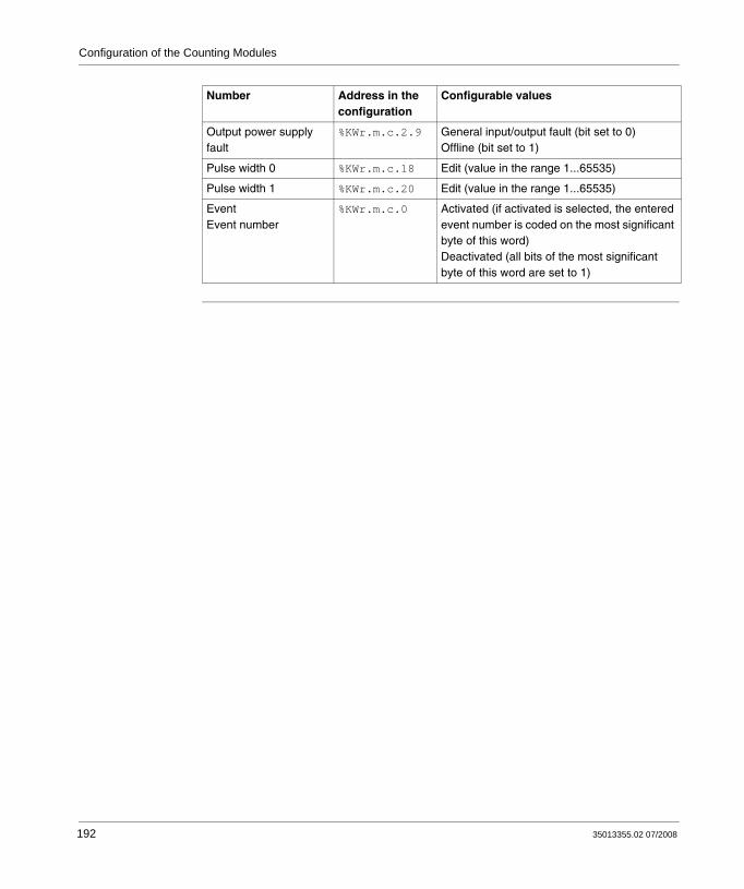
Configuration of the Counting Modules
Output power supply fault
%KWr.m.c.2.9 General input/output fault (bit set to 0)Offline (bit set to 1)
Pulse width 0 %KWr.m.c.18 Edit (value in the range 1...65535)
Pulse width 1 %KWr.m.c.20 Edit (value in the range 1...65535)
EventEvent number
%KWr.m.c.0 Activated (if activated is selected, the entered event number is coded on the most significant byte of this word)Deactivated (all bits of the most significant byte of this word are set to 1)
Number Address in the configuration
Configurable values
192 35013355.02 07/2008

Configuration of the Counting Modules
One Shot Counter Mode Configuration
At a Glance The configuration of a counting module is stored in the configuration constants (%KW).
The parameters r,m and c shown in the following tables represent the topologic addressing of the module. Each parameter had the following signification:
r: represents the rack number,m:represents the position of the module on the rack,c: represents the channel number.
Configuration Objects
The table below presents the one shot counter mode configurable elements
Number Address in the configuration
Configurable values
Counting mode %KWr.m.c.2(least significant byte)
One shot counter mode. The value of the least significant byte of this word is 6.
IN_A input filter %KWr.m.c.3(least significant byte)
The least significant byte can take the following values:
0: none,1: low,2: medium,3: high.
IN_SYNC input filter %KWr.m.c.4(least significant byte)
The least significant byte can take the following values:
0: none,1: low,2: medium,3: high.
IN_EN input filter %KWr.m.c.4(most significant byte)
The most significant byte can take the following values:
0: none,1: low,2: medium,3: high.
Input power supply fault
%KWr.m.c.2.8 General input/output fault (bit set to 0)Local (bit set to 1)
Scale factor %KWr.m.c.6(least significant byte)
Edit (value in the range 1...255)
35013355.02 07/2008 193

Configuration of the Counting Modules
Synchronization edge %KWr.m.c.10.8 Rising edge (bit set to 0)Falling edge (bit set to 1)
Output block 0 %KWr.m.c.17 This word can take the following values:0: off,1: low counter,2: counter in a window,3: High counter,4: pulse = less than the lower threshold (LT),5: pulse = greater than the lower threshold (LT),6: pulse = less than the upper threshold (UT),7: pulse = greater than the upper threshold (UT).
Output block 1 %KWr.m.c.19 This word can take the following values:0: off,1: low counter,2: counter in a window,3: High counter,4: pulse = less than the lower threshold (LT),5: pulse = greater than the lower threshold (LT),6: pulse = less than the upper threshold (UT),7: pulse = greater than the upper threshold (UT).
Polarity 0 %KWr.m.c.21.1 Polarity + (bit set to 0)Polarity - (bit set to 1)
Polarity 1 %KWr.m.c.21.2 Polarity + (bit set to 0)Polarity - (bit set to 1)
Fault recovery %KWr.m.c.21.0 Automatic reaction (bit set to 1)Activated (bit set to 0)
Fallback 0 %KWr.m.c.21.3 None (bit set to 0)With (bit set to 1)
Fallback 1 %KWr.m.c.21.4 None (bit set to 0)With (bit set to 1)
Fallback value 0 %KWr.m.c.21.5 0 (bit set to 0)1 (bit set to 1)
Fallback value 1 %KWr.m.c.21.6 0 (bit set to 0)1 (bit set to 1)
Number Address in the configuration
Configurable values
194 35013355.02 07/2008

Configuration of the Counting Modules
Output power supply fault
%KWr.m.c.2.9 General input/output fault (bit set to 0)Offline (bit set to 1)
Pulse width 0 %KWr.m.c.18 Edit (value in the range 1...65535)
Pulse width 1 %KWr.m.c.20 Edit (value in the range 1...65535)
EventEvent number
%KWr.m.c.0 Activated (if activated is selected, the entered event number is coded on the most significant byte of this word)Deactivated (all bits of the most significant byte of this word are set to 1)
Number Address in the configuration
Configurable values
35013355.02 07/2008 195
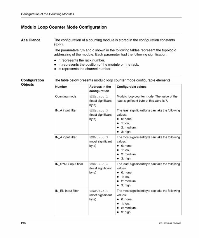
Configuration of the Counting Modules
Modulo Loop Counter Mode Configuration
At a Glance The configuration of a counting module is stored in the configuration constants (%KW).
The parameters r,m and c shown in the following tables represent the topologic addressing of the module. Each parameter had the following signification:
r: represents the rack number,m:represents the position of the module on the rack,c: represents the channel number.
Configuration Objects
The table below presents modulo loop counter mode configurable elements.
Number Address in the configuration
Configurable values
Counting mode %KWr.m.c.2(least significant byte)
Modulo loop counter mode. The value of the least significant byte of this word is 7.
IN_A input filter %KWr.m.c.3(least significant byte)
The least significant byte can take the following values:
0: none,1: low,2: medium,3: high.
IN_A input filter %KWr.m.c.3(most significant byte)
The most significant byte can take the following values:
0: none,1: low,2: medium,3: high.
IN_SYNC input filter %KWr.m.c.4(least significant byte)
The least significant byte can take the following values:
0: none,1: low,2: medium,3: high.
IN_EN input filter %KWr.m.c.4(most significant byte)
The most significant byte can take the following values:
0: none,1: low,2: medium,3: high.
196 35013355.02 07/2008

Configuration of the Counting Modules
Input power supply fault
%KWr.m.c.2.8 General input/output fault (bit set to 0)Local (bit set to 1)
Input mode %KWr.m.c.9 This word can take the following values:0: A = High, B = Low,1: A = Pulse, B = Direction,2: normal quadrature 1,3: normal quadrature 2,4: normal quadrature 4,5: inverse quadrature 1,6: inverse quadrature 2,7: inverse quadrature 4.
Scale factor %KWr.m.c.6(least significant byte)
Edit (value in the range 1...255)
Synchronization edge %KWr.m.c.10(most significant byte)
Rising edge (bit set to 0)Falling edge (bit set to 1)
Output block 0 %KWr.m.c.17 This word can take the following values:0: off,1: low counter,2: counter in a window,3: High counter,4: pulse = less than the lower threshold (LT),5: pulse = greater than the lower threshold (LT),6: pulse = less than the upper threshold (UT),7: pulse = greater than the upper threshold (UT).
Number Address in the configuration
Configurable values
35013355.02 07/2008 197

Configuration of the Counting Modules
Output block 1 %KWr.m.c.19 This word can take the following values:0: off,1: low counter,2: counter in a window,3: High counter,4: pulse = less than the lower threshold (LT),5: pulse = greater than the lower threshold (LT),6: pulse = less than the upper threshold (UT),7: pulse = greater than the upper threshold (UT).
Polarity 0 %KWr.m.c.21.1 Polarity + (bit set to 0)Polarity - (bit set to 1)
Polarity 1 %KWr.m.c.21.2 Polarity + (bit set to 0)Polarity - (bit set to 1)
Fault recovery %KWr.m.c.21.0 Automatic reaction (bit set to 1)Activated (bit set to 0)
Fallback 0 %KWr.m.c.21.3 None (bit set to 0)With (bit set to 1)
Fallback 1 %KWr.m.c.21.4 None (bit set to 0)With (bit set to 1)
Fallback value 0 %KWr.m.c.21.5 0 (bit set to 0)1 (bit set to 1)
Fallback value 1 %KWr.m.c.21.6 0 (bit set to 0)1 (bit set to 1)
Output power supply fault
%KWr.m.c.2.9 General input/output fault (bit set to 0)Offline (bit set to 1)
Pulse width 0 %KWr.m.c.18 Edit (value in the range 1...65535)
Pulse width 1 %KWr.m.c.20 Edit (value in the range 1...65535)
EventEvent number
%KWr.m.c.0 Activated (if activated is selected, the entered event number is coded on the most significant byte of this word)Deactivated (all bits of the most significant byte of this word are set to 1)
Number Address in the configuration
Configurable values
198 35013355.02 07/2008
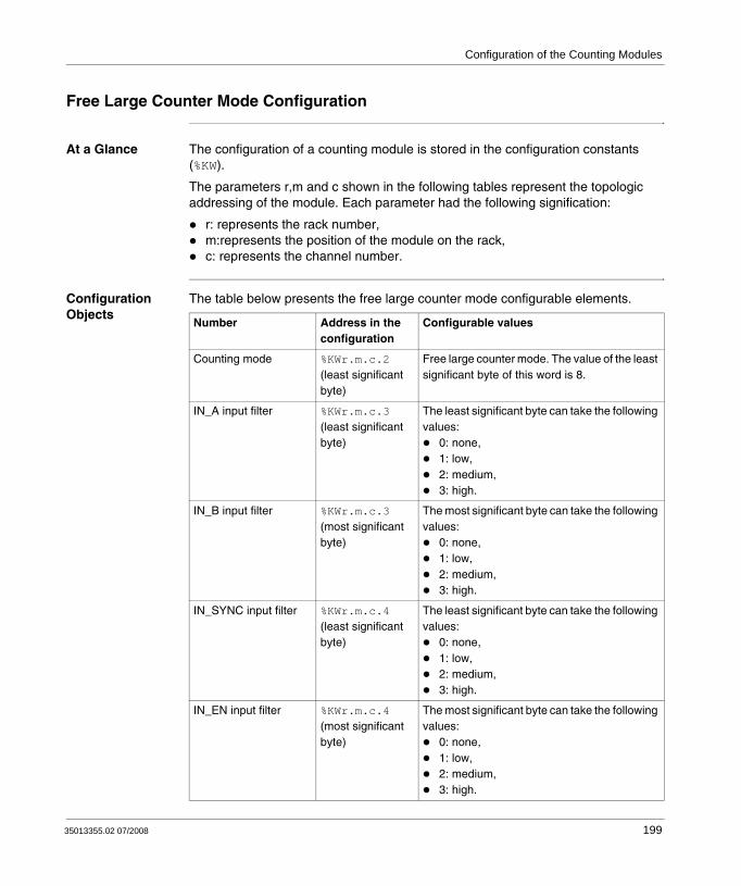
Configuration of the Counting Modules
Free Large Counter Mode Configuration
At a Glance The configuration of a counting module is stored in the configuration constants (%KW).
The parameters r,m and c shown in the following tables represent the topologic addressing of the module. Each parameter had the following signification:
r: represents the rack number,m:represents the position of the module on the rack,c: represents the channel number.
Configuration Objects
The table below presents the free large counter mode configurable elements.
Number Address in the configuration
Configurable values
Counting mode %KWr.m.c.2(least significant byte)
Free large counter mode. The value of the least significant byte of this word is 8.
IN_A input filter %KWr.m.c.3(least significant byte)
The least significant byte can take the following values:
0: none,1: low,2: medium,3: high.
IN_B input filter %KWr.m.c.3(most significant byte)
The most significant byte can take the following values:
0: none,1: low,2: medium,3: high.
IN_SYNC input filter %KWr.m.c.4(least significant byte)
The least significant byte can take the following values:
0: none,1: low,2: medium,3: high.
IN_EN input filter %KWr.m.c.4(most significant byte)
The most significant byte can take the following values:
0: none,1: low,2: medium,3: high.
35013355.02 07/2008 199

Configuration of the Counting Modules
IN_REF input filter %KWr.m.c.5(least significant byte)
The least significant byte can take the following values:
0: none,1: low,2: medium,3: high.
IN_CAP input filter %KWr.m.c.5(most significant byte)
The most significant byte can take the following values:
0: none,1: low,2: medium,3: high.
Input power supply fault
%KWr.m.c.2.8 General input/output fault (bit set to 0)Local (bit set to 1)
Input mode %KWr.m.c.9 This word can take the following values:0: A = High, B = Low1: A = Pulse, B = Direction2: normal quadrature 13: normal quadrature 24: normal quadrature 45: inverse quadrature 16: inverse quadrature 27: inverse quadrature 4
Scale factor %KWr.m.c.6(least significant byte)
Edit (value in the range 1...255)
Preset mode %KWr.m.c.10(least significant byte)
The least significant byte can take the following values:
0: rising edge at IN_SYNC1: rising edge at IN_REF2: rising edge at IN_SYNC and IN_REF3: first rising edge at IN_SYNC and IN_REF at 14: first rising edge at IN_SYNC and IN_REF at 0
Capture 0 settings %KWr.m.c.16.1 Preset condition (bit set to 0)Falling edge at the IN_CAP input (bit set to 1)
Number Address in the configuration
Configurable values
200 35013355.02 07/2008

Configuration of the Counting Modules
Output block 0 %KWr.m.c.17 This word can take the following values:0: off,1: low counter,2: counter in a window,3: High counter,4: pulse = less than the lower threshold (LT),5: pulse = greater than the lower threshold (LT),6: pulse = less than the upper threshold (UT),7: pulse = greater than the upper threshold (UT).
Output block 1 %KWr.m.c.19 This word can take the following values:0: off,1: low counter,2: counter in a window,3: High counter,4: pulse = less than the lower threshold (LT),5: pulse = greater than the lower threshold (LT),6: pulse = less than the upper threshold (UT),7: pulse = greater than the upper threshold (UT).
Polarity 0 %KWr.m.c.21.1 Polarity + (bit set to 0)Polarity - (bit set to 1)
Polarity 1 %KWr.m.c.21.2 Polarity + (bit set to 0)Polarity - (bit set to 1)
Fault recovery %KWr.m.c.21.0 Automatic reaction (bit set to 1)Activated (bit set to 0)
Fallback 0 %KWr.m.c.21.3 None (bit set to 0)With (bit set to 1)
Fallback 1 %KWr.m.c.21.4 None (bit set to 0)With (bit set to 1)
Fallback value 0 %KWr.m.c.21.5 0 (bit set to 0)1 (bit set to 1)
Fallback value 1 %KWr.m.c.21.6 0 (bit set to 0)1 (bit set to 1)
Number Address in the configuration
Configurable values
35013355.02 07/2008 201

Configuration of the Counting Modules
Output power supply fault
%KWr.m.c.2.9 General input/output fault (bit set to 0)Offline (bit set to 1)
Pulse width 0 %KWr.m.c.18 Edit (value in the range 1...65535)
Pulse width 1 %KWr.m.c.20 Edit (value in the range 1...65535)
EventEvent number
%KWr.m.c.0 Activated (if activated is selected, the entered event number is coded on the most significant byte of this word)Deactivated (all bits of the most significant byte of this word are set to 1)
Number Address in the configuration
Configurable values
202 35013355.02 07/2008
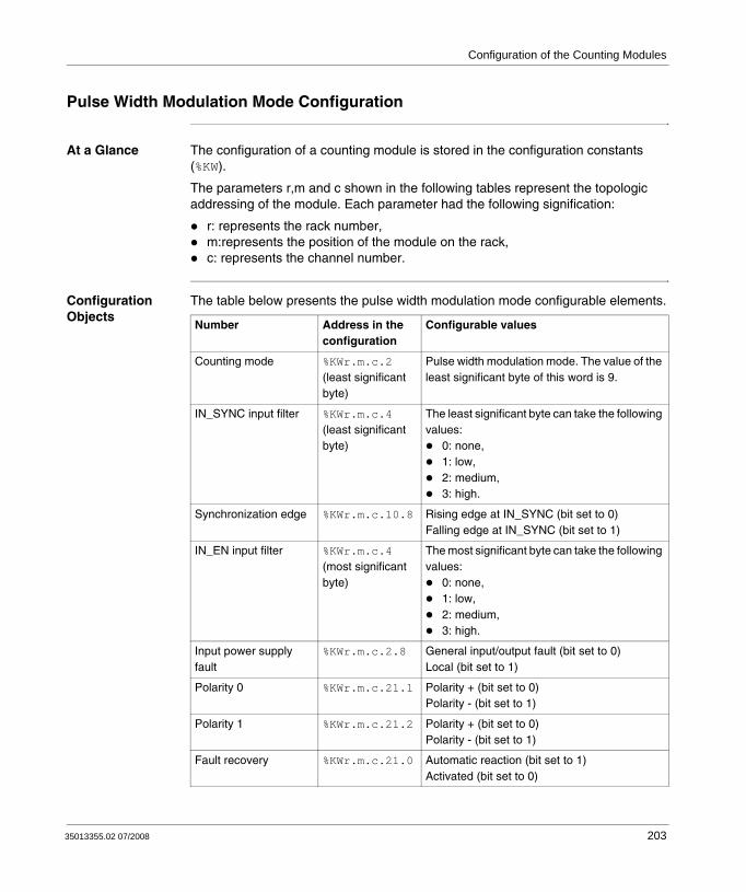
Configuration of the Counting Modules
Pulse Width Modulation Mode Configuration
At a Glance The configuration of a counting module is stored in the configuration constants (%KW).
The parameters r,m and c shown in the following tables represent the topologic addressing of the module. Each parameter had the following signification:
r: represents the rack number,m:represents the position of the module on the rack,c: represents the channel number.
Configuration Objects
The table below presents the pulse width modulation mode configurable elements.
Number Address in the configuration
Configurable values
Counting mode %KWr.m.c.2(least significant byte)
Pulse width modulation mode. The value of the least significant byte of this word is 9.
IN_SYNC input filter %KWr.m.c.4(least significant byte)
The least significant byte can take the following values:
0: none,1: low,2: medium,3: high.
Synchronization edge %KWr.m.c.10.8 Rising edge at IN_SYNC (bit set to 0)Falling edge at IN_SYNC (bit set to 1)
IN_EN input filter %KWr.m.c.4(most significant byte)
The most significant byte can take the following values:
0: none,1: low,2: medium,3: high.
Input power supply fault
%KWr.m.c.2.8 General input/output fault (bit set to 0)Local (bit set to 1)
Polarity 0 %KWr.m.c.21.1 Polarity + (bit set to 0)Polarity - (bit set to 1)
Polarity 1 %KWr.m.c.21.2 Polarity + (bit set to 0)Polarity - (bit set to 1)
Fault recovery %KWr.m.c.21.0 Automatic reaction (bit set to 1)Activated (bit set to 0)
35013355.02 07/2008 203

Configuration of the Counting Modules
Fallback 0 %KWr.m.c.21.3 None (bit set to 0)With (bit set to 1)
Fallback 1 %KWr.m.c.21.4 None (bit set to 0)With (bit set to 1)
Fallback value 0 %KWr.m.c.21.5 0 (bit set to 0)1 (bit set to 1)
Fallback value 1 %KWr.m.c.21.6 0 (bit set to 0)1 (bit set to 1)
Output power supply fault
%KWr.m.c.2.9 General input/output fault (bit set to 0)Offline (bit set to 1)
EventEvent number
%KWr.m.c.0 Activated (if activated is selected, the entered event number is coded on the most significant byte of this word)Deactivated (all bits of the most significant byte of this word are set to 1)
Number Address in the configuration
Configurable values
204 35013355.02 07/2008

Configuration of the Counting Modules
11.3 Configuration of Modes for the BMX EHC 0800 Module
At a Glance
Subject of this Section
This section deals with the configuration of the modes for the BMX EHC 0800 counting modules.
What's in this Section?
This section contains the following topics:
Topic Page
Frequency Mode Configuration 206
Event Counting Mode Configuration 207
One Shot Counter Mode Configuration 209
Modulo Loop Counter Mode Configuration 211
Up and Down Counting Mode Configuration 212
Dual Phase Counting Mode Configuration 213
35013355.02 07/2008 205

Configuration of the Counting Modules
Frequency Mode Configuration
At a Glance The configuration of a counting module is stored in the configuration constants (%KW).
The parameters r,m and c shown in the following tables represent the topologic addressing of the module. Each parameter had the following signification:
r: represents the rack number,m:represents the position of the module on the rack,c: represents the channel number.
Configuration Objects
The table below presents the frequency mode configurable elements.
Number Address in the configuration
Configurable values
Counting mode %KWr.m.c.2(least significant byte)
Frequency mode. The value of the least significant byte of this word is 1.
IN_A input filter %KWr.m.c.3(least significant byte)
The least significant byte can take the following values:
0: none,1: low,2: medium,3: high.
Input power supply fault
%KWr.m.c.2.8 General input/output fault (bit set to 0)Local (bit set to 1)
Scale factor %KWr.m.c.6(least significant byte)
Edit (value in the range 1...255)
EventEvent number
%KWr.m.c.0 Activated (if activated is selected, the entered event number is coded on the most significant byte of this word)Deactivated (all bits of the most significant byte of this word are set to 1)
206 35013355.02 07/2008

Configuration of the Counting Modules
Event Counting Mode Configuration
At a Glance The configuration of a counting module is stored in the configuration constants (%KW).
The parameters r,m and c shown in the following tables represent the topologic addressing of the module. Each parameter had the following signification:
r: represents the rack number,m:represents the position of the module on the rack,c: represents the channel number.
Configuration Objects
The table below presents the event counting mode configurable elements.
Number Address in the configuration
Configurable values
Counting mode %KWr.m.c.2(least significant byte)
Event counting mode. The value of the least significant byte of this word is 2.
IN_A input filter %KWr.m.c.3(least significant byte)
The least significant byte can take the following values:
0: none,1: low,2: medium,3: high.
IN_AUX input filter %KWr.m.c.4(least significant byte)
The least significant byte can take the following values:
0: none,1: low,2: medium,3: high.
Input power supply fault
%KWr.m.c.2.8 General input/output fault (bit set to 0)Local (bit set to 1)
Synchronization edge %KWr.m.c.10.8(most significant byte)
Rising edge at the IN_SYNC input (bit set to 0)Falling edge at the IN_SYNC input (bit set to 1)
Time base %KWr.m.c.7 This word can take the following values:0: 0.1 s,1: 1 s,2: 10 s,3: 1 min
35013355.02 07/2008 207

Configuration of the Counting Modules
EventEvent number
%KWr.m.c.0 Activated (if activated is selected, the entered event number is coded on the most significant byte of this word)Deactivated (all bits of the most significant byte of this word are set to 1)
Number Address in the configuration
Configurable values
208 35013355.02 07/2008

Configuration of the Counting Modules
One Shot Counter Mode Configuration
At a Glance The configuration of a counting module is stored in the configuration constants (%KW).
The parameters r,m and c shown in the following tables represent the topologic addressing of the module. Each parameter had the following signification:
r: represents the rack number,m:represents the position of the module on the rack,c: represents the channel number.
Configuration Objects
The table below presents the one shot counter mode configurable elements.
Number Address in the configuration
Configurable values
Counting mode %KWr.m.c.2(least significant byte)
One shot counter mode. The value of the least significant byte of this word is 3.
IN_A input filter %KWr.m.c.3(least significant byte)
The least significant byte can take the following values:
0: none,1: low,2: medium,3: high.
IN_AUX input filter %KWr.m.c.4(least significant byte)
The least significant byte can take the following values:
0: none,1: low,2: medium,3: high.
IN_EN input filter %KWr.m.c.4(most significant byte)
The most significant byte can take the following values:
0: none,1: low,2: medium,3: high.
Input power supply fault %KWr.m.c.2.8 General input/output fault (bit set to 0)Local (bit set to 1)
Scale factor %KWr.m.c.6(least significant byte)
Edit (value in the range 1...255)
35013355.02 07/2008 209

Configuration of the Counting Modules
Synchronization edge %KWr.m.c.10.8(High)
Rising edge (bit set to 0)Falling edge (bit set to 1)
EventEvent number
%KWr.m.c.0 Activated (if activated is selected, the entered event number is coded on the most significant byte of this word)Deactivated (all bits of the most significant byte of this word are set to 1)
Number Address in the configuration
Configurable values
210 35013355.02 07/2008

Configuration of the Counting Modules
Modulo Loop Counter Mode Configuration
At a Glance The configuration of a counting module is stored in the configuration constants (%KW).
The parameters r,m and c shown in the following tables represent the topologic addressing of the module. Each parameter had the following signification:
r: represents the rack number,m:represents the position of the module on the rack,c: represents the channel number.
Configuration Objects
The table below presents modulo loop counter mode configurable elements.
Number Address in the configuration
Configurable values
Counting mode %KWr.m.c.2(least significant byte)
Modulo loop counter mode. The value of the least significant byte of this word is 4.
IN_A input filter %KWr.m.c.3(least significant byte)
The least significant byte can take the following values:
0: none,1: low,2: medium,3: high.
IN_AUX input filter %KWr.m.c.4(least significant byte)
The least significant byte can take the following values:
0: none,1: low,2: medium,3: high.
Input power supply fault %KWr.m.c.2.8 General input/output fault (bit set to 0)Local (bit set to 1)
Scale factor %KWr.m.c.6(least significant byte)
Edit (value in the range 1...255)
Synchronization edge %KWr.m.c.10.8 Rising edge (bit set to 0)Falling edge (bit set to 1)
EventEvent number
%KWr.m.c.0 Activated (if activated is selected, the entered event number is coded on the most significant byte of this word)Deactivated (all bits of the most significant byte of this word are set to 1)
35013355.02 07/2008 211

Configuration of the Counting Modules
Up and Down Counting Mode Configuration
At a Glance The configuration of a counting module is stored in the configuration constants (%KW).
The parameters r,m and c shown in the following tables represent the topologic addressing of the module. Each parameter had the following signification:
r: represents the rack number,m:represents the position of the module on the rack,c: represents the channel number.
Configuration Objects
The table below presents the up and down counting mode configurable elements.
Number Address in the configuration
Configurable values
Counting mode %KWr.m.c.2(least significant byte)
Up and down counting mode. The value of the least significant byte of this word is 5.
IN_A input filter %KWr.m.c.3(least significant byte)
The least significant byte can take the following values:
0: none,1: low,2: medium,3: high.
IN_AUX input filter %KWr.m.c.4(least significant byte)
The least significant byte can take the following values:
0: none,1: low,2: medium,3: high.
Input power supply fault %KWr.m.c.2.8 General input/output fault (bit set to 0)Local (bit set to 1)
Counting operation %KWr.m.c.11.0 Overrun locking (bit set to 0)Reversal (bit set to 1)
Synchronization edge %KWr.m.c.10.8(High)
Rising edge (bit set to 0)Falling edge (bit set to 1)
EventEvent number
%KWr.m.c.0 Activated (if activated is selected, the entered event number is coded on the most significant byte of this word)Deactivated (all bits of the most significant byte of this word are set to 1)
212 35013355.02 07/2008

Configuration of the Counting Modules
Dual Phase Counting Mode Configuration
At a Glance The configuration of a counting module is stored in the configuration constants (%KW).
The parameters r,m and c shown in the following tables represent the topologic addressing of the module. Each parameter had the following signification:
r: represents the rack number,m:represents the position of the module on the rack,c: represents the channel number.
Configuration Objects
The table below presents the dual phase counting mode configurable elements.
Number Address in the configuration
Configurable values
Counting mode %KWr.m.c.2(least significant byte)
Dual phase counting mode. The value of the least significant byte of this word is 6.
IN_A input filter %KWr.m.c.3(least significant byte)
The least significant byte can take the following values:
0: none,1: low,2: medium,3: high.
IN_B input filter %KWr.m.c.3(most significant byte)
The most significant byte can take the following values:
0: none,1: low,2: medium,3: high.
IN_AUX input filter %KWr.m.c.4(least significant byte)
The least significant byte can take the following values:
0: none,1: low,2: medium,3: high.
Input power supply fault %KWr.m.c.2.8 General input/output fault (bit set to 0)Local (bit set to 1)
35013355.02 07/2008 213

Configuration of the Counting Modules
Input mode %KWr.m.c.9 This word can take the following values:0: A = High, B = Low1: A = Pulse, B = Direction2: normal quadrature 13: normal quadrature 24: normal quadrature 45: inverse quadrature 16: inverse quadrature 27: inverse quadrature 4
Scale factor %KWr.m.c.6(least significant byte)
Edit (value in the range 1...255)
Synchronization edge %KWr.m.c.10.8 Rising edge (bit set to 0)Falling edge (bit set to 1)
Counting operation %KWr.m.c.11.0 Overrun locking (bit set to 0)Reversal (bit set to 1)
EventEvent number
%KWr.m.c.0 Activated (if activated is selected, the entered event number is coded on the most significant byte of this word)Deactivated (all bits of the most significant byte of this word are set to 1)
Number Address in the configuration
Configurable values
214 35013355.02 07/2008

35013355.02 07/2008
12
BMX EHC xxxx Counting Module SettingsAt a Glance
Subject of this Section
This section deals with the possible settings for the counting modes of the BMX EHC •••• modules. These settings can be accessed from the Configuration tab on the functional screens of BMX EHC •••• modules (see Description of the Counting Module Screens, p. 174).
What's in this Chapter?
This chapter contains the following topics:
Topic Page
Adjust Screen for BMX EHC xxxx Counting Modules 216
Setting the Preset Value 218
Setting the Calibration Factor 219
Modulo Setting 220
Setting the Hysteresis Value 221
215

Counting Module Settings
Adjust Screen for BMX EHC xxxx Counting Modules
At a Glance This section presents the adjust screen for BMX EHC •••• counting modules.
Illustration The figure below presents the adjust screen for the BMX EHC 0200 module in modulo loop counter mode:
1 2 3 4 5
2 channel generic counter Version : 1.00Run Err IO
Config. FaultDebugAdjust
Function:
Task:Modulo Loop-Coun
BMX EHC 0200
Counter 1 - Modulo LCounter 0 - Modulo L
MAST
Label Symbol ValueModulo m3_0200_0.Modulo_VALU
UnitInit value15 150
module4_E 0.3: BMX E...
6
216 35013355.02 07/2008

Counting Module Settings
Description of the Screen
The following table presents the various parts of the above screen:
Number Element Function
1 Label field This field contains the name of each variable that may be adjusted. This field may not be modified and can be accessed in both local and online modes.
2 Tab The tab in the foreground indicates the current mode. The current mode is therefore the adjust mode in this example.
3 Symbol field This field contains the mnemonics of the variable. This field may not be modified and can be accessed in both offline and online modes.
4 Initial value field
This field displays the value of the variable that the user has adjusted in offline mode. This field is only accessible in online mode.
5 Value field The function of this field depends on the mode in which the user is working:
In offline mode: this field is used to adjust the variable.In online mode: this field is used to display the current value of the variable.
6 Unit field This field contains the unit of each variable that may be configured. This field may not be modified and can be accessed in both offline and online modes.
35013355.02 07/2008 217

Counting Module Settings
Setting the Preset Value
Introduction The preset value concerns the following counting modes:
for the BMX EHC 0200 module:one shot counter modefree large counter mode
for the BMX EHC 0800 module:dual phase counting modeup and down-counting mode.
Description The following table shows the preset value setting:
Number Address in the configuration
Value Default value
Preset value %MDr.m.c.12 (Low) Edit 0
218 35013355.02 07/2008

Counting Module Settings
Setting the Calibration Factor
Introduction The calibration factor concerns the frequency and ratio modes for the BMX EHC 0200 module and the frequency mode for the BMX EHC 0800 module.
Description The following table shows the calibration factor setting:
Number Address in the configuration
Value Default value
Calibration factor
%MWr.m.c.14 Edit 0
35013355.02 07/2008 219
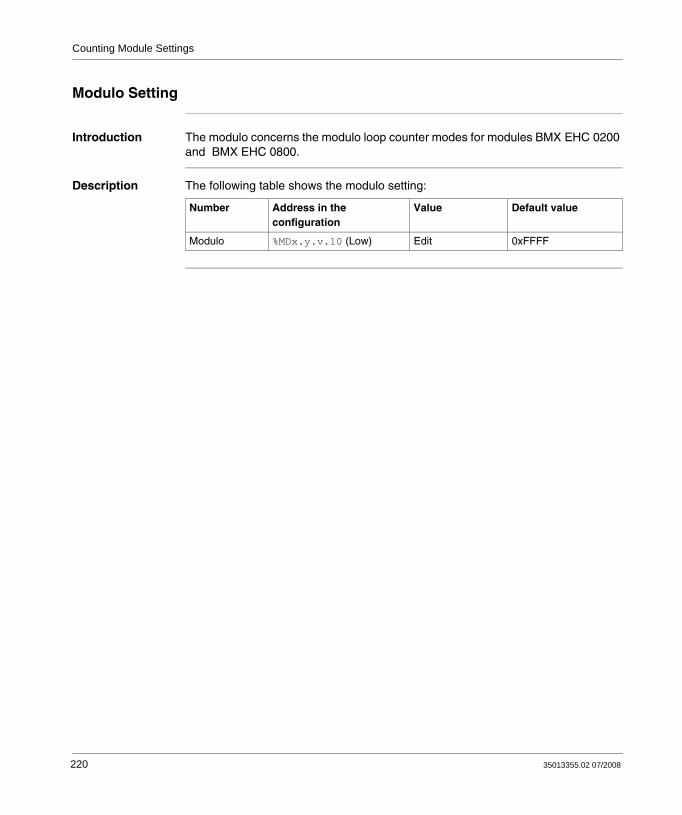
Counting Module Settings
Modulo Setting
Introduction The modulo concerns the modulo loop counter modes for modules BMX EHC 0200 and BMX EHC 0800.
Description The following table shows the modulo setting:
Number Address in the configuration
Value Default value
Modulo %MDx.y.v.10 (Low) Edit 0xFFFF
220 35013355.02 07/2008

Counting Module Settings
Setting the Hysteresis Value
Introduction The hysteresis value concerns free large counter mode for module BMX EHC 0200 and dual phase counting mode for BMX EHC 0800 module.
Description The following table shows the setting for the hysteresis value:
Number Address in the configuration
Value Default value
Hysteresis(release value)
%MWr.m.c.9 Edit 0
35013355.02 07/2008 221

Counting Module Settings
222 35013355.02 07/2008
35013355.02 07/2008
13
Debugging the BMX EHC xxxx Counting ModulesAt a Glance
Subject of this Chapter
This chapter deals with the debugging settings applicable to BMX EHC •••• modules. These settings can be accessed from the Debug tab on the functional screens of the BMX EHC•••• (see Accessing the Functional Screens of the BMX EHC xxxx Counting Modules , p. 172) modules.
What's in this Chapter?
This chapter contains the following sections:
Section Topic Page
13.1 Debug Screen for BMX EHC xxxx Counting Modules 224
13.2 BMX EHC 0200 Module Debugging 227
13.3 BMX EHC 0800 Module Debugging 238
223

Debugging the Counting Modules
13.1 Debug Screen for BMX EHC xxxx Counting Modules
Debug Screen for BMX EHC xxxx Counting Modules
At a Glance This section presents the debug screen for BMX EHC •••• counting modules. A module’s debug screen can only be accessed in online mode.
224 35013355.02 07/2008

Debugging the Counting Modules
Illustration The figure below presents the debug screen for the BMX EHC 0200 module in modulo loop counter mode:
1 2 3 4 5
2 channel generic counter Version : 1.00Run Err IO
Config. FaultDebugAdjust
Function:
Task:Modulo Loop-Coun
BMX EHC 0200
Counter 1 - Modulo LCounter 0 - Modulo L
MAST
module4_E 0.3: BMX E...
Reference Label Symbol Value%ID0.3.0.2 Counter value m3_0200_0.COUNTER_CURRENT_VALUE0 0%IW0.3.0.0.3 Counter Valid m3_0200_0.COUNTER_STATUS1 No%IW0.3.0.1.0 Counter low m3_0200_0.COOMPARE_STATUS2 No%IW0.3.0.1.1 Counter in window m3_0200_0.COOMPARE_STATUS3 No%IW0.3.0.1.2 Counter high m3_0200_0.COOMPARE_STATUS4 No%IW0.3.0.0.5 Counter in low limit m3_0200_0.COUNTER_STATUS5 No%IW0.3.0.0.4 Counter in high limit m3_0200_0.COUNTER_STATUS6 No%ID0.3.0.4 Capture 0 value m3_0200_0.CAPT_0_VALUE7 0%IW0.3.0.1.3 Capture 0 low m3_0200_0.COOMPARE_STATUS8 No%IW0.3.0.1.4 Capture 0 in window m3_0200_0.COOMPARE_STATUS9 No%IW0.3.0.1.5 Capture 0 high m3_0200_0.COOMPARE_STATUS10 No%QW0.3.0.0.3 Capture 0 enable m3_0200_0.FUNCTIONS_ENABLING11 0%I0.3.0.4 Input A m3_0200_0.INPUT__A12 0%I0.3.0.5 Input B m3_0200_0.INPUT__B13 0%I0.3.0.6 Input SYNC m3_0200_0.INPUT_SYNC14 0%QW0.3.0.0.0 SYNC enable m3_0200_0.FUNCTIONS_ENABLING15 0%Q0.3.0.4 SYNC force m3_0200_0.FORCE_SYNC16 0%IW0.3.0.0.2 SYNC state m3_0200_0.COUNTER_STATUS17 Yes%Q0.3.0.8 SYNC reset m3_0200_0.SYNC_RESET18 0%Q0.3.0.7 Input EN m3_0200_0.INPUT_EN19 0%QW0.3.0.0.2 EN enable m3_0200_0.FUNCTIONS_ENABLING20 0%Q0.3.0.6 Counter enable m3_0200_0.FORCE_ENABLE21 1%I0.0.0.0 Output 0 state m3_0200_0.OUTPUT_0_Echo22 0%Q0.3.0.0 Output 0 cmd m3_0200_0.OUTPUT_023 0%I0.3.0.1 Output 1 state m3_0200_0.OUTPUT_1_Echo24 0%Q0.3.0.1 Output 1 cmd m3_0200_0.OUTPUT_125 0%Q0.3.0.7 Counter reset m3_0200_0.FORCE_RESET26 0%I0.3.0.2 Output latch 0 state m3_0200_0.OUTPUT_BLOCK_027 0%Q0.3.0.2 Output latch 0 enable m3_0200_0.OUTPUT_BLOCK_0_ENABLE28 0%I0.3.0.3 Output latch 1 state m3_0200_0.OUTPUT_BLOCK_129 0%Q0.3.0.3 Output latch 1 enable m3_0200_0.OUTPUT_BLOCK_1_ENABLE30 0%QD0.3.0.2 Low threshold value m3_0200_0.LOWER_TH_VALUE31 0%QD0.3.0.4 High threshold value m3_0200_0.UPPER_TH_VALUE32 12%QW0.3.0.0.5 Compare enable m3_0200_0.FUNCTIONS_ENABLING33 1%QW0.3.0.0.6 Compare suspend m3_0200_0.FUNCTIONS_ENABLING34 0%IW0.3.0.0.1 Modulo flag m3_0200_0.COUNTER_STATUS35 Yes%Q0.3.0.9 Modulo reset m3_0200_0.MODULO_RESET36 0
35013355.02 07/2008 225
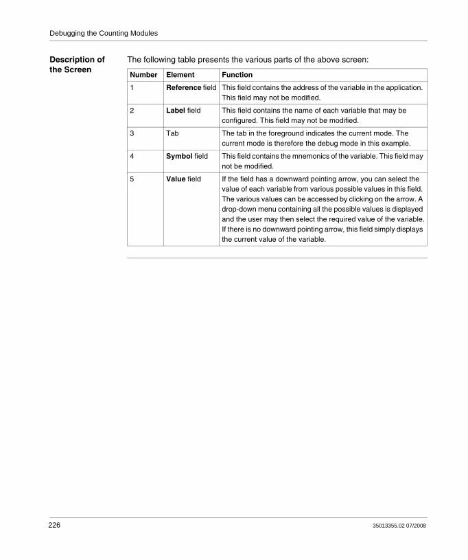
Debugging the Counting Modules
Description of the Screen
The following table presents the various parts of the above screen:
Number Element Function
1 Reference field This field contains the address of the variable in the application. This field may not be modified.
2 Label field This field contains the name of each variable that may be configured. This field may not be modified.
3 Tab The tab in the foreground indicates the current mode. The current mode is therefore the debug mode in this example.
4 Symbol field This field contains the mnemonics of the variable. This field may not be modified.
5 Value field If the field has a downward pointing arrow, you can select the value of each variable from various possible values in this field. The various values can be accessed by clicking on the arrow. A drop-down menu containing all the possible values is displayed and the user may then select the required value of the variable.If there is no downward pointing arrow, this field simply displays the current value of the variable.
226 35013355.02 07/2008

Debugging the Counting Modules
13.2 BMX EHC 0200 Module Debugging
At a Glance
Subject of this Section
This section deals with the debugging of the BMX EHC 0200 counting module modes.
What's in this Section?
This section contains the following topics:
Topic Page
Frequency Mode Debugging 228
Event Counting Mode Debugging 229
Period Measuring Mode Debugging 230
Ratio Mode Debugging 231
One Shot Counter Mode Debugging 232
Modulo Loop Counter Mode Debugging 233
Free Large Counter Mode Debugging 235
Pulse Width Modulation Mode Debugging 237
35013355.02 07/2008 227
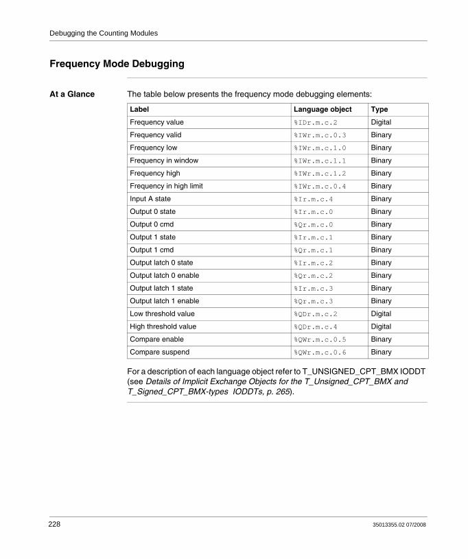
Debugging the Counting Modules
Frequency Mode Debugging
At a Glance The table below presents the frequency mode debugging elements:
For a description of each language object refer to T_UNSIGNED_CPT_BMX IODDT (see Details of Implicit Exchange Objects for the T_Unsigned_CPT_BMX and T_Signed_CPT_BMX-types IODDTs, p. 265).
Label Language object Type
Frequency value %IDr.m.c.2 Digital
Frequency valid %IWr.m.c.0.3 Binary
Frequency low %IWr.m.c.1.0 Binary
Frequency in window %IWr.m.c.1.1 Binary
Frequency high %IWr.m.c.1.2 Binary
Frequency in high limit %IWr.m.c.0.4 Binary
Input A state %Ir.m.c.4 Binary
Output 0 state %Ir.m.c.0 Binary
Output 0 cmd %Qr.m.c.0 Binary
Output 1 state %Ir.m.c.1 Binary
Output 1 cmd %Qr.m.c.1 Binary
Output latch 0 state %Ir.m.c.2 Binary
Output latch 0 enable %Qr.m.c.2 Binary
Output latch 1 state %Ir.m.c.3 Binary
Output latch 1 enable %Qr.m.c.3 Binary
Low threshold value %QDr.m.c.2 Digital
High threshold value %QDr.m.c.4 Digital
Compare enable %QWr.m.c.0.5 Binary
Compare suspend %QWr.m.c.0.6 Binary
228 35013355.02 07/2008

Debugging the Counting Modules
Event Counting Mode Debugging
At a Glance The table below presents the event counting mode debugging elements:
For a description of each language object refer to T_UNSIGNED_CPT_BMX IODDT (see Details of Implicit Exchange Objects for the T_Unsigned_CPT_BMX and T_Signed_CPT_BMX-types IODDTs, p. 265).
Label Language object Type
Counter value %IDr.m.c.2 Digital
Counter valid %IWr.m.c.0.3 Binary
Counter low %IWr.m.c.1.0 Binary
Counter in window %IWr.m.c.1.1 Binary
Counter high %IWr.m.c.1.2 Binary
Counter in low limit %IWr.m.c.0.5 Binary
Counter in high limit %IWr.m.c.0.4 Binary
Input A state %Ir.m.c.4 Binary
Input SYNC state %Ir.m.c.6 Binary
SYNC enable %QWr.m.c.0.0 Binary
SYNC force %Qr.m.c.4 Binary
SYNC state %IWr.m.c.0.2 Binary
SYNC reset %Qr.m.c.8 Binary
Output 0 state %Ir.m.c.0 Binary
Output 0 cmd %Qr.m.c.0 Binary
Output 1 state %Ir.m.c.1 Binary
Output 1 cmd %Qr.m.c.1 Binary
Output latch 0 state %Ir.m.c.2 Binary
Output latch 0 enable %Qr.m.c.2 Binary
Output latch 1 state %Ir.m.c.3 Binary
Output latch 1 enable %Qr.m.c.3 Binary
Low threshold value %QDr.m.c.2 Digital
High threshold value %QDr.m.c.4 Digital
Compare enable %QWr.m.c.0.5 Binary
Compare suspend %QWr.m.c.0.6 Binary
35013355.02 07/2008 229

Debugging the Counting Modules
Period Measuring Mode Debugging
At a Glance The table below presents the period measuring mode debugging elements:
For a description of each language object refer to T_UNSIGNED_CPT_BMX IODDT (see Details of Implicit Exchange Objects for the T_Unsigned_CPT_BMX and T_Signed_CPT_BMX-types IODDTs, p. 265).
Label Language object Type
Period value %IDr.m.c.2 Digital
Period valid %IWr.m.c.0.3 Binary
Period low %IWr.m.c.1.0 Binary
Period in window %IWr.m.c.1.1 Binary
Period high %IWr.m.c.1.2 Binary
Period in low limit %IWr.m.c.0.5 Binary
Period in high limit %IWr.m.c.0.4 Binary
Input A state %Ir.m.c.4 Binary
Input SYNC state %Ir.m.c.6 Binary
SYNC enable %QWr.m.c.0.0 Binary
SYNC force %Qr.m.c.4 Binary
SYNC state %IWr.m.c.0.2 Binary
SYNC reset %Qr.m.c.8 Binary
Output 0 state %Ir.m.c.0 Binary
Output 0 cmd %Qr.m.c.0 Binary
Output 1 state %Ir.m.c.1 Binary
Output 1 cmd %Qr.m.c.1 Binary
Output latch 0 state %Ir.m.c.2 Binary
Output latch 0 enable %Qr.m.c.2 Binary
Output latch 1 state %Ir.m.c.3 Binary
Output latch 1 enable %Qr.m.c.3 Binary
Low threshold value %QDr.m.c.2 Digital
High threshold value %QDr.m.c.4 Digital
Compare enable %QWr.m.c.0.5 Binary
Compare suspend %QWr.m.c.0.6 Binary
230 35013355.02 07/2008

Debugging the Counting Modules
Ratio Mode Debugging
At a Glance The table below presents the ratio mode debugging elements:
For a description of each language object refer to T_SIGNED_CPT_BMX IODDT (see Details of Implicit Exchange Objects for the T_Unsigned_CPT_BMX and T_Signed_CPT_BMX-types IODDTs, p. 265).
Label Language object Type
Ratio value %IDr.m.c.2 Digital
Ratio valid %IWr.m.c.0.3 Binary
Ratio low %IWr.m.c.1.0 Binary
Ratio in window %IWr.m.c.1.1 Binary
Ratio high %IWr.m.c.1.2 Binary
Ratio in low limit %IWr.m.c.0.5 Binary
Ratio in high limit %IWr.m.c.0.4 Binary
Input A state %Ir.m.c.4 Binary
Input B state %Ir.m.c.5 Binary
Output 0 state %Ir.m.c.0 Binary
Output 0 cmd %Qr.m.c.0 Binary
Output 1 state %Ir.m.c.1 Binary
Output 1 cmd %Qr.m.c.1 Binary
Output latch 0 state %Ir.m.c.2 Binary
Output latch 0 enable %Qr.m.c.2 Binary
Output latch 1 state %Ir.m.c.3 Binary
Output latch 1 enable %Qr.m.c.3 Binary
Low threshold value %QDr.m.c.2 Digital
High threshold value %QDr.m.c.4 Digital
Compare enable %QWr.m.c.0.5 Binary
Compare suspend %QWr.m.c.0.6 Binary
35013355.02 07/2008 231

Debugging the Counting Modules
One Shot Counter Mode Debugging
At a Glance The table below presents the one shot counter mode debugging elements:
For a description of each language object refer to T_UNSIGNED_CPT_BMX IODDT (see Details of Implicit Exchange Objects for the T_Unsigned_CPT_BMX and T_Signed_CPT_BMX-types IODDTs, p. 265).
Label Language object Type
Counter value %IDr.m.c.2 Digital
Counter valid %IWr.m.c.0.3 Binary
Counter low %IWr.m.c.1.0 Binary
Counter in window %IWr.m.c.1.1 Binary
Counter high %IWr.m.c.1.2 Binary
RUN %IWr.m.c.0.0 Binary
Input A state %Ir.m.c.4 Binary
Input SYNC state %Ir.m.c.6 Binary
SYNC enable %QWr.m.c.0.0 Binary
SYNC force %Qr.m.c.4 Binary
SYNC state %IWr.m.c.0.2 Binary
SYNC reset %Qr.m.c.8 Binary
Input EN %Ir.m.c.7 Binary
EN enable %QWr.m.c.0.2 Binary
Counter enable %Qr.m.c.6 Binary
Output 0 state %Ir.m.c.0 Binary
Output 0 cmd %Qr.m.c.0 Binary
Output 1 state %Ir.m.c.1 Binary
Output 1 cmd %Qr.m.c.1 Binary
Output latch 0 state %Ir.m.c.2 Binary
Output latch 0 enable %Qr.m.c.2 Binary
Output latch 1 state %Ir.m.c.3 Binary
Output latch 1 enable %Qr.m.c.3 Binary
Low threshold value %QDr.m.c.2 Digital
High threshold value %QDr.m.c.4 Digital
Compare enable %QWr.m.c.0.5 Binary
Compare suspend %QWr.m.c.0.6 Binary
232 35013355.02 07/2008

Debugging the Counting Modules
Modulo Loop Counter Mode Debugging
At a Glance The table below presents the modulo loop counter mode debugging elements:
Label Language object Type
Counter value %IDr.m.c.2 Digital
Counter valid %IWr.m.c.0.3 Binary
Counter low %IWr.m.c.1.0 Binary
Counter in window %IWr.m.c.1.1 Binary
Counter high %IWr.m.c.1.2 Binary
Counter in low limit %IWr.m.c.0.5 Binary
Counter in high limit %IWr.m.c.0.4 Binary
Capture value %IDr.m.c.4 Digital
Capture low %IWr.m.c.1.3 Binary
Capture in window %IWr.m.c.1.4 Binary
Capture high %IWr.m.c.1.5 Binary
Capture enable %QWr.m.c.0.3 Binary
Input A state %Ir.m.c.4 Binary
Input B state %Ir.m.c.5 Binary
Input SYNC state %Ir.m.c.6 Binary
SYNC enable %QWr.m.c.0.0 Binary
SYNC force %Qr.m.c.4 Binary
SYNC state %IWr.m.c.0.2 Binary
SYNC reset %QWr.m.c.8 Binary
Input EN %Ir.m.c.7 Binary
EN enable %QWr.m.c.0.2 Binary
Counter enable %Qr.m.c.6 Binary
Output 0 state %Ir.m.c.0 Binary
Output 0 cmd %Qr.m.c.0 Binary
Output 1 state %Ir.m.c.1 Binary
Output 1 cmd %Qr.m.c.1 Binary
Counter reset %Qr.m.c.7 Binary
Output latch 0 state %Ir.m.c.2 Binary
Output latch 0 enable %Qr.m.c.2 Binary
Output latch 1 state %Ir.m.c.3 Binary
35013355.02 07/2008 233

Debugging the Counting Modules
For a description of each language object refer to T_UNSIGNED_CPT_BMX IODDT (see Details of Implicit Exchange Objects for the T_Unsigned_CPT_BMX and T_Signed_CPT_BMX-types IODDTs, p. 265).
Output latch 01enable %Qr.m.c.3 Binary
Low threshold value %QDr.m.c.2 Digital
High threshold value %QDr.m.c.4 Digital
Compare enable %QWr.m.c.0.5 Binary
Compare suspend %QWr.m.c.0.6 Binary
Modulo state %IWr.m.c.0.1 Binary
Modulo reset %Qr.m.c.9 Binary
Label Language object Type
234 35013355.02 07/2008

Debugging the Counting Modules
Free Large Counter Mode Debugging
At a Glance The table below presents the free large counter mode debugging elements:
Label Language object Type
Counter value %IDr.m.c.2 Digital
Counter valid %IWr.m.c.0.3 Binary
Counter low %IWr.m.c.1.0 Binary
Counter in window %IWr.m.c.1.1 Binary
Counter high %IWr.m.c.1.2 Binary
Counter in low limit %IWr.m.c.0.5 Binary
Counter in high limit %IWr.m.c.0.4 Binary
Capture 0 value %IDr.m.c.4 Digital
Capture 0 low %IWr.m.c.1.3 Binary
Capture 0 in window %IWr.m.c.1.4 Binary
Capture 0 high %IWr.m.c.1.5 Binary
Capture 0 enable %QWr.m.c.0.3 Binary
Capture 1 value %IDr.m.c.16 Digital
Capture 1 low %IWr.m.c.1.6 Binary
Capture 1 in window %IWr.m.c.1.7 Binary
Capture 1 high %IWr.m.c.1.8 Binary
Capture 1 enable %QWr.m.c.0.4 Binary
Input A state %Ir.m.c.4 Binary
Input B state %Ir.m.c.5 Binary
IN_SYNC input %Ir.m.c.6 Binary
Modulo state %IWr.m.c.0.1 Binary
Modulo reset %Qr.m.c.9 Binary
SYNC state %IWr.m.c.0.2 Binary
SYNC reset %Qr.m.c.8 Binary
Input EN %Ir.m.c.7 Binary
EN enable %QWr.m.c.0.2 Binary
Counter enable %Qr.m.c.6 Binary
Input REF %Ir.m.c.8 Binary
REF enable %QWr.m.c.0.1 Binary
REF force %QWr.m.c.5 Binary
35013355.02 07/2008 235
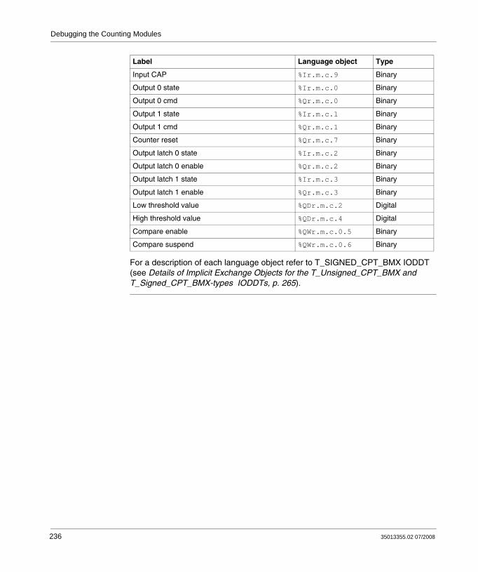
Debugging the Counting Modules
For a description of each language object refer to T_SIGNED_CPT_BMX IODDT (see Details of Implicit Exchange Objects for the T_Unsigned_CPT_BMX and T_Signed_CPT_BMX-types IODDTs, p. 265).
Input CAP %Ir.m.c.9 Binary
Output 0 state %Ir.m.c.0 Binary
Output 0 cmd %Qr.m.c.0 Binary
Output 1 state %Ir.m.c.1 Binary
Output 1 cmd %Qr.m.c.1 Binary
Counter reset %Qr.m.c.7 Binary
Output latch 0 state %Ir.m.c.2 Binary
Output latch 0 enable %Qr.m.c.2 Binary
Output latch 1 state %Ir.m.c.3 Binary
Output latch 1 enable %Qr.m.c.3 Binary
Low threshold value %QDr.m.c.2 Digital
High threshold value %QDr.m.c.4 Digital
Compare enable %QWr.m.c.0.5 Binary
Compare suspend %QWr.m.c.0.6 Binary
Label Language object Type
236 35013355.02 07/2008
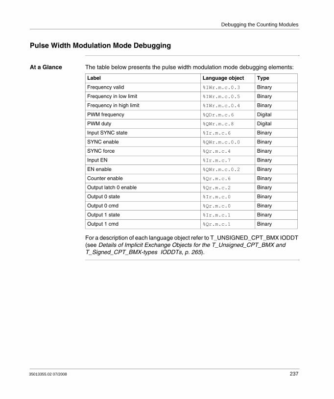
Debugging the Counting Modules
Pulse Width Modulation Mode Debugging
At a Glance The table below presents the pulse width modulation mode debugging elements:
For a description of each language object refer to T_UNSIGNED_CPT_BMX IODDT (see Details of Implicit Exchange Objects for the T_Unsigned_CPT_BMX and T_Signed_CPT_BMX-types IODDTs, p. 265).
Label Language object Type
Frequency valid %IWr.m.c.0.3 Binary
Frequency in low limit %IWr.m.c.0.5 Binary
Frequency in high limit %IWr.m.c.0.4 Binary
PWM frequency %QDr.m.c.6 Digital
PWM duty %QWr.m.c.8 Digital
Input SYNC state %Ir.m.c.6 Binary
SYNC enable %QWr.m.c.0.0 Binary
SYNC force %Qr.m.c.4 Binary
Input EN %Ir.m.c.7 Binary
EN enable %QWr.m.c.0.2 Binary
Counter enable %Qr.m.c.6 Binary
Output latch 0 enable %Qr.m.c.2 Binary
Output 0 state %Ir.m.c.0 Binary
Output 0 cmd %Qr.m.c.0 Binary
Output 1 state %Ir.m.c.1 Binary
Output 1 cmd %Qr.m.c.1 Binary
35013355.02 07/2008 237

Debugging the Counting Modules
13.3 BMX EHC 0800 Module Debugging
At a Glance
Subject of this Section
This section deals with the debugging of the BMX EHC 0800 counting module modes.
What's in this Section?
This section contains the following topics:
Topic Page
Frequency Mode Debugging 239
Event Counting Mode Debugging 240
One Shot Counter Mode Debugging 241
Modulo Loop Counter Mode Debugging 242
Up and Down Counting Mode Debugging 243
Dual Phase Counting Mode Debugging 244
238 35013355.02 07/2008

Debugging the Counting Modules
Frequency Mode Debugging
At a Glance The table below presents the frequency mode debugging elements:
For a description of each language object refer to T_UNSIGNED_CPT_BMX IODDT (see Details of Implicit Exchange Objects for the T_Unsigned_CPT_BMX and T_Signed_CPT_BMX-types IODDTs, p. 265).
Label Language object Type
Frequency value %IDr.m.c.2 Digital
Frequency valid %IWr.m.c.0.3 Binary
Frequency low %IWr.m.c.1.0 Binary
Frequency equal %IWr.m.c.1.1 Binary
Frequency high %IWr.m.c.1.2 Binary
Frequency in high limit %IWr.m.c.0.4 Binary
Input A state %Ir.m.c.4 Binary
Threshold value %QDr.m.c.2 Digital
Compare enable %QWr.m.c.0.5 Binary
Compare suspend %QWr.m.c.0.6 Binary
35013355.02 07/2008 239

Debugging the Counting Modules
Event Counting Mode Debugging
At a Glance The table below presents the event counting mode debugging elements.
For a description of each language object refer to T_UNSIGNED_CPT_BMX IODDT (see Details of Implicit Exchange Objects for the T_Unsigned_CPT_BMX and T_Signed_CPT_BMX-types IODDTs, p. 265).
Label Language object Type
Counter value %IDr.m.c.2 Digital
Counter valid %IWr.m.c.0.3 Binary
Counter low %IWr.m.c.1.0 Binary
Counter equal %IWr.m.c.1.1 Binary
Counter high %IWr.m.c.1.2 Binary
Counter in low limit %IWr.m.c.0.5 Binary
Counter in high limit %IWr.m.c.0.4 Binary
Input A state %Ir.m.c.4 Binary
Input AUX state %Ir.m.c.6 Binary
SYNC enable %QWr.m.c.0.0 Binary
SYNC force %Qr.m.c.4 Binary
SYNC state %IWr.m.c.0.2 Binary
SYNC reset %QWr.m.c.8 Binary
Threshold value %QDr.m.c.2 Digital
Compare enable %QWr.m.c.0.5 Binary
Compare suspend %QWr.m.c.0.6 Binary
240 35013355.02 07/2008

Debugging the Counting Modules
One Shot Counter Mode Debugging
At a Glance The table below presents the one shot counter mode debugging elements:
For a description of each language object refer to T_UNSIGNED_CPT_BMX IODDT (see Details of Implicit Exchange Objects for the T_Unsigned_CPT_BMX and T_Signed_CPT_BMX-types IODDTs, p. 265).
Label Language object Type
Counter value %IDr.m.c.2 Digital
Counter valid %IWr.m.c.0.3 Binary
RUN %IWr.m.c.0.0 Binary
Counter reset %Qr.m.c.7 Binary
Counter enable %Qr.m.c.6 Binary
Counter low %IWr.m.c.1.0 Binary
Counter equal %IWr.m.c.1.1 Binary
Counter high %IWr.m.c.1.2 Binary
Input A state %Ir.m.c.4 Binary
Input AUX state %Ir.m.c.6 Binary
SYNC enable %QWr.m.c.0.0 Binary
SYNC force %Qr.m.c.4 Binary
SYNC state %IWr.m.c.0.2 Binary
SYNC reset %QWr.m.c.8 Binary
Threshold value %QDr.m.c.2 Digital
Compare enable %QWr.m.c.0.5 Binary
Compare suspend %QWr.m.c.0.6 Binary
35013355.02 07/2008 241
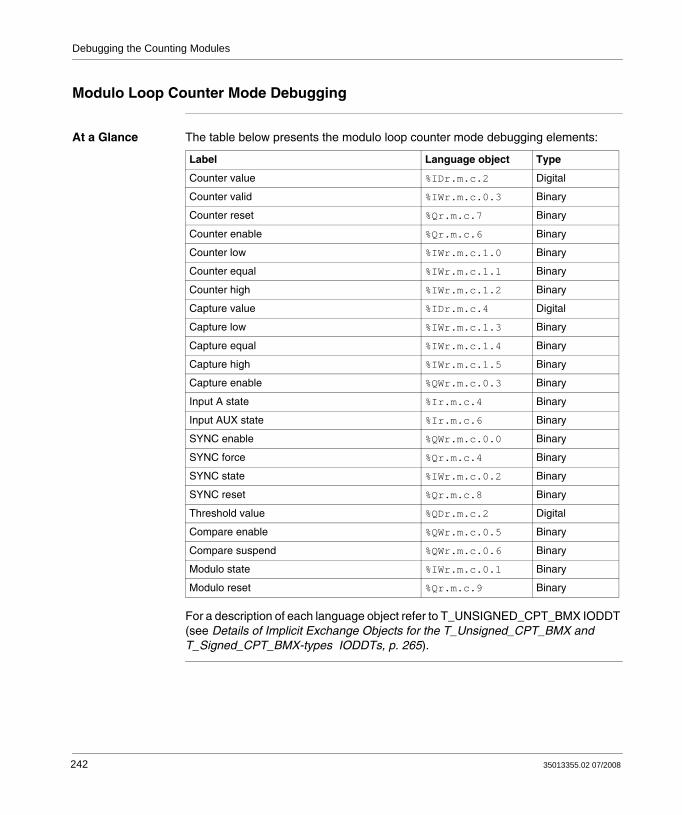
Debugging the Counting Modules
Modulo Loop Counter Mode Debugging
At a Glance The table below presents the modulo loop counter mode debugging elements:
For a description of each language object refer to T_UNSIGNED_CPT_BMX IODDT (see Details of Implicit Exchange Objects for the T_Unsigned_CPT_BMX and T_Signed_CPT_BMX-types IODDTs, p. 265).
Label Language object Type
Counter value %IDr.m.c.2 Digital
Counter valid %IWr.m.c.0.3 Binary
Counter reset %Qr.m.c.7 Binary
Counter enable %Qr.m.c.6 Binary
Counter low %IWr.m.c.1.0 Binary
Counter equal %IWr.m.c.1.1 Binary
Counter high %IWr.m.c.1.2 Binary
Capture value %IDr.m.c.4 Digital
Capture low %IWr.m.c.1.3 Binary
Capture equal %IWr.m.c.1.4 Binary
Capture high %IWr.m.c.1.5 Binary
Capture enable %QWr.m.c.0.3 Binary
Input A state %Ir.m.c.4 Binary
Input AUX state %Ir.m.c.6 Binary
SYNC enable %QWr.m.c.0.0 Binary
SYNC force %Qr.m.c.4 Binary
SYNC state %IWr.m.c.0.2 Binary
SYNC reset %Qr.m.c.8 Binary
Threshold value %QDr.m.c.2 Digital
Compare enable %QWr.m.c.0.5 Binary
Compare suspend %QWr.m.c.0.6 Binary
Modulo state %IWr.m.c.0.1 Binary
Modulo reset %Qr.m.c.9 Binary
242 35013355.02 07/2008

Debugging the Counting Modules
Up and Down Counting Mode Debugging
At a Glance The table below presents the up and down counting mode debugging elements:
For a description of each language object refer to T_SIGNED_CPT_BMX IODDT (see Details of Implicit Exchange Objects for the T_Unsigned_CPT_BMX and T_Signed_CPT_BMX-types IODDTs, p. 265).
Label Language object Type
Counter value %IDr.m.c.2 Digital
Counter valid %IWr.m.c.0.3 Binary
Counter reset %Qr.m.c.7 Binary
Counter enable %Qr.m.c.6 Binary
Counter low %IWr.m.c.1.0 Binary
Counter equal %IWr.m.c.1.1 Binary
Counter high %IWr.m.c.1.2 Binary
Counter in low limit %IWr.m.c.0.5 Binary
Counter in high limit %IWr.m.c.0.4 Binary
Input A state %Ir.m.c.4 Binary
Input AUX state %Ir.m.c.6 Binary
SYNC force %Qr.m.c.4 Binary
SYNC state %IWr.m.c.0.2 Binary
SYNC reset %Qr.m.c.8 Binary
Threshold value %QDr.m.c.2 Digital
Compare enable %QWr.m.c.0.5 Binary
Compare suspend %QWr.m.c.0.6 Binary
Modulo state %IWr.m.c.0.1 Binary
Modulo reset %Qr.m.c.9 Binary
35013355.02 07/2008 243

Debugging the Counting Modules
Dual Phase Counting Mode Debugging
At a Glance The table below presents the dual phase counting mode debugging elements:
For a description of each language object refer to T_UNSIGNED_CPT_BMX IODDT (see Details of Implicit Exchange Objects for the T_Unsigned_CPT_BMX and T_Signed_CPT_BMX-types IODDTs, p. 265).
Label Language object Type
Counter value %IDr.m.c.2 Digital
Counter valid %IWr.m.c.0.3 Binary
Counter reset %Qr.m.c.7 Binary
Counter enable %Qr.m.c.6 Binary
Counter low %IWr.m.c.1.0 Binary
Counter equal %IWr.m.c.1.1 Binary
Counter high %IWr.m.c.1.2 Binary
Counter in low limit %IWr.m.c.0.5 Binary
Counter in high limit %IWr.m.c.0.4 Binary
Capture value %IDr.m.c.4 Digital
Capture low %IWr.m.c.1.3 Binary
Capture equal %IWr.m.c.1.4 Binary
Capture high %IWr.m.c.1.5 Binary
Capture enable %QWr.m.c.0.3 Binary
Input A state %Ir.m.c.4 Binary
Input B state %Ir.m.c.5 Binary
Input AUX state %Ir.m.c.6 Binary
SYNC enable %QWr.m.c.0.0 Binary
SYNC force %Qr.m.c.4 Binary
SYNC state %IWr.m.c.0.2 Binary
SYNC reset %Qr.m.c.8 Binary
Threshold value %QDr.m.c.2 Digital
Compare enable %QWr.m.c.0.5 Binary
Compare suspend %QWr.m.c.0.6 Binary
Modulo state %IWr.m.c.0.1 Binary
Modulo reset %Qr.m.c.9 Binary
244 35013355.02 07/2008

35013355.02 07/2008
14
Display of BMX EHC xxxx Counting Module FaultsAt a Glance
Subject of this Section
This section deals with the display of possible faults for the BMX EHC•••• modules.
What's in this Chapter?
This chapter contains the following topics:
Topic Page
Fault Display Screen for BMX EHC xxxx Counting Modules 246
Faults Diagnostics Display 248
List of Faults 249
245

Display of Faults, Counting Module
Fault Display Screen for BMX EHC xxxx Counting Modules
At a Glance This section presents the fault display screen for BMX EHC •••• counting modules. A module’s fault display screen may only be accessed in online mode.
Illustration The figure below presents the fault display screen for the BMX EHC 0200 module in modulo loop counter mode.
1 2 3 4
2 channel generic counter Version : 1.00Run Err IO
Config. FaultDebugAdjust
Function:
Task:Modulo Loop-Coun
BMX EHC 0200
Counter 1 - Modulo LCounter 0 - Modulo L
MAST
module4_E 0.3: BMX E...
- External Fault on Inputs- External Fault on Outputs- Input sensor supply low voltage- Output sensor supply low voltage
External fault Other fault Internal fault
MW : 0x3 MW : 0xc
246 35013355.02 07/2008

Display of Faults, Counting Module
Description of the Screen
The following table presents the various parts of the above screen.
Number Element Function
1 Internal faults field This field displays the module’s active internal faults.
2 Tab The tab in the foreground indicates the current mode. The current mode is therefore the fault display mode in this example.
3 External faults field This field displays the module’s active external faults.
4 Other faults field This field displays the module’s active faults, other than internal and external faults.
35013355.02 07/2008 247

Display of Faults, Counting Module
Faults Diagnostics Display
At a Glance The diagnostic screens (see Accessing the Functional Screens of the BMX EHC xxxx Counting Modules, p. 171) on the module or channel are only accessible in connected mode. When an un-masked fault appears, it is reported:
in the configuration screen of the rack, with the presence of a red square in the position of the faulty counting module,in all screens at module level (Description and Fault tabs),
in the module field with the LEDin all channel level screens (Configuration, Adjustment, Debug and Fault tabs),
in the module zone with the LEDin the channel zone with the fault LED
in the fault screen that is accessed by the Fault where the fault diagnostics are described.
The fault is also signaled:
On the module, on the central display,by dedicated language objects: CH_ERROR (%Ir.m.c.ERR) and MOD_ERROR (%Ir.m.MOD.ERR), %MWr.m.MOD.2, etc. and status words.
Note: Even if the fault is masked, it is reported by the flashing of the I/O LED and in the fault screen.
248 35013355.02 07/2008
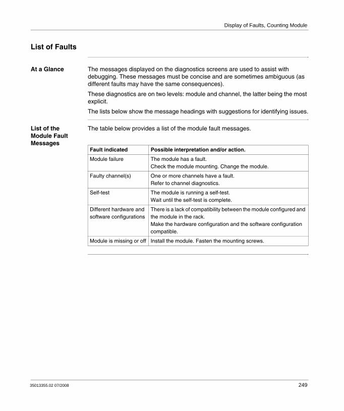
Display of Faults, Counting Module
List of Faults
At a Glance The messages displayed on the diagnostics screens are used to assist with debugging. These messages must be concise and are sometimes ambiguous (as different faults may have the same consequences).
These diagnostics are on two levels: module and channel, the latter being the most explicit.
The lists below show the message headings with suggestions for identifying issues.
List of the Module Fault Messages
The table below provides a list of the module fault messages.
Fault indicated Possible interpretation and/or action.
Module failure The module has a fault.Check the module mounting. Change the module.
Faulty channel(s) One or more channels have a fault.Refer to channel diagnostics.
Self-test The module is running a self-test.Wait until the self-test is complete.
Different hardware and software configurations
There is a lack of compatibility between the module configured and the module in the rack.Make the hardware configuration and the software configuration compatible.
Module is missing or off Install the module. Fasten the mounting screws.
35013355.02 07/2008 249

Display of Faults, Counting Module
BMX EHC 0200 Module Faults
The table below provides a list of faults that may appear on the BMX EHC 0200 module.
BMX EHC 0800 Module Faults
The table below provides a list of faults that may appear on the BMX EHC 0800 module.
Language object Description
%MWr.m.c.2.0 External fault at inputs
%MWr.m.c.2.1 External fault at outputs
%MWr.m.c.2.4 Internal error or self-testing.
%MWr.m.c.2.5 Configuration Fault
%MWr.m.c.2.6 Communication Error
%MWr.m.c.2.7 Application fault
%MWr.m.c.3.2 Sensor power supply fault
%MWr.m.c.3.3 Actuator supply fault
%MWr.m.c.3.4 Short circuit on output 0
%MWr.m.c.3.5 Short circuit on output 1
Language object Description
%MWr.m.c.2.0 External fault at inputs
%MWr.m.c.2.4 Internal error or self-testing.
%MWr.m.c.2.5 Configuration Fault
%MWr.m.c.2.6 Communication Error
%MWr.m.c.2.7 Application fault
%MWr.m.c.3.2 Sensor power supply fault
250 35013355.02 07/2008

Display of Faults, Counting Module
List of Channel Fault Messages
The table below gives the list of fault messages at channel level.
Fault indicated. Other consequences.
Possible interpretation and/or action.
External fault or counting input fault:encoder or proximity sensor supply faultline break or short circuit of at least one encoder differential signal (1A, 1B, 1Z)specific fault on absolute encoder
Outputs are set to 0 in automatic mode.Invalid measurement message.
Check the sensor connections.Check the sensor power supply.Check the sensor operation.Delete the fault and acknowledge if the fault storing is configured.Counting pulses or incremental encoder: preset or reset to acknowledge the Invalid measurement message.
Counting application fault:measurement overrunoverspeed
Outputs are set to 0 in automatic mode.Invalid measurement message.
Diagnose the fault more precisely (external causes).Check the application again, if necessary.Delete the fault and acknowledge if the fault storing is configured.Counting pulses or incremental encoder: preset or reset to 0 to acknowledge the Invalid measurement message.
Auxiliary input/output fault:power supplyshort circuit of at least one output
Outputs are set to 0 in automatic mode
Check the output connectionsCheck the input/output power supply (24V)Diagnose the fault more precisely (external causes)Delete the fault and acknowledge if the fault storing is configured
Internal error or channel self-testing:module faultymodule missing or offmodule running self-test
Module fault has gone down to channel level.Refer to module level diagnostics.
Different hardware and software configurations
Module fault has gone down to channel level.Refer to module level diagnostics.
Invalid software configuration:incorrect constantbit combination not associated with any configuration
Check and modify the configuration constants.
Communication error Check the connections between the racks.
Application fault: refusal to configure or adjust
Diagnose the fault more precisely.
35013355.02 07/2008 251

Display of Faults, Counting Module
252 35013355.02 07/2008
35013355.02 07/2008
15
The Language Objects of the Counting FunctionAt a Glance
Subject of this Chapter
This chapter describes the language objects associated to the counting tasks as well as the different ways of using them.
What's in this Chapter?
This chapter contains the following sections:
Section Topic Page
15.1 The Language Objects and IODDT of the Counting Function 254
15.2 Language Objects and IODDT Associated with the Counting Function of the BMX EHC xxxx Modules.
264
15.3 The IODDT Type T_GEN_MOD Applicable to All Modules 274
253
The Language Objects of the Counting Function
15.1 The Language Objects and IODDT of the Counting Function
At a Glance
Subject of this Section
This section describes the general features of the language objects and IODDT of the counting function.
What's in this Section?
This section contains the following topics:
Topic Page
Introducing Language Objects for Application-Specific Counting 255
Implicit Exchange Language Objects Associated with the Application-Specific Function
256
Explicit Exchange Language Objects Associated with the Application-Specific Function
257
Management of Exchanges and Reports with Explicit Objects 259
254 35013355.02 07/2008

The Language Objects of the Counting Function
Introducing Language Objects for Application-Specific Counting
General The counting modules have only two associated IODDTs. These IODDTs are predefined by the manufacturer and contains language objects for inputs/outputs belonging to the channel of an application-specific module.
The IODDT associated with the counting modules are of T_ Unsigned_CPT_BMX and T_Signed_CPT_BMX types.
Language Object Types
Each IODDT contains a set of language objects allowing its operation to be controlled and checked.
There are two types of language objects:
Implicit Exchange Objects: these objects are automatically exchanged on each cycle revolution of the task associated with the module.Explicit Exchange Objects: these objects are exchanged on the application's request, using explicit exchange instructions.
Implicit exchanges concern the inputs/outputs of the module (measurement results, information and commands). These exchanges enable the debugging of the counting modules.
Explicit exchanges enable the module to be set and diagnosed.
Note: IODDT variables can be created in two different ways:Using the I/O objects (See Unity Pro, Operating Modes, I/O Objects Tab for a Module) tab.Using the Data Editor (See Unity Pro, Operating Modes, Create an IODDT Data Instance).
35013355.02 07/2008 255

The Language Objects of the Counting Function
Implicit Exchange Language Objects Associated with the Application-Specific Function
At a Glance An integrated application-specific interface or the addition of a module automatically enhances the language objects application used to program this interface or module.
These objects correspond to the input/output images and software data of the module or integrated application-specific interface.
Reminders The module inputs (%I and %IW) are updated in the PLC memory at the start of the task, the PLC being in RUN or STOP mode.
The outputs (%Q and %QW) are updated at the end of the task, only when the PLC is in RUN mode.
Figure The following diagram shows the operating cycle of a PLC task (cyclical execution).
Note: When the task occurs in STOP mode, either of the following are possible, depending on the configuration selected:
outputs are set to fallback position (fallback mode)outputs are maintained at their last value (maintain mode)
Internal processing
Acquisition of inputs
Execution of the program
Update of outputs
RUN STOP
256 35013355.02 07/2008

The Language Objects of the Counting Function
Explicit Exchange Language Objects Associated with the Application-Specific Function
Introduction Explicit exchanges are performed at the user program's request using these instructions:
READ_STS (see Unity Pro I/O Management Block Library, READ_STS: Reading the status parameters) (read status words)WRITE_CMD (see Unity Pro I/O Management Block Library, WRITE_CMD: Updating the command parameters) (write command words)WRITE_PARAM (see Unity Pro I/O Management Block Library, WRITE_PARAM: Updating the adjustment parameters) (write adjustment parameters)READ_PARAM (see Unity Pro I/O Management Block Library, READ_PARAM: Reading the adjustment parameters) (read adjustment parameters)SAVE_PARAM (see Unity Pro I/O Management Block Library, SAVE_PARAM: Saving the adjustment parameters) (save adjustment parameters)RESTORE_PARAM (see Unity Pro I/O Management Block Library, RESTORE_PARAM: Restoring the adjustment parameters) (restore adjustment parameters)
These exchanges apply to a set of %MW objects of the same type (status, commands or parameters) that belong to a channel.
Note: These objects can:
provide information about the module (for example, type of channel fault)have command control of the module (for example, switch command) define the module’s operating modes (save and restore adjustment parameters in the process of application)
Note: In order to avoid several simultaneous explicit exchanges for the same channel, it is necessary to test the value of the word EXCH_STS (%MWr.m.c.0) of the IODDT associated to the channel before calling any EF addressing this channel.
35013355.02 07/2008 257

The Language Objects of the Counting Function
General Principle for Using Explicit Instructions
The diagram below shows the different types of explicit exchanges that can be made between the application and module.
Managing Exchanges
During an explicit exchange, it is necessary to check performance to ensure data is only taken into account when the exchange has been correctly executed.
To do this, two types of information is available:information concerning the exchange in progress (see Execution Indicators for an Explicit Exchange: EXCH_STS, p. 262)the exchange report (see Explicit Exchange Report: EXCH_RPT, p. 262)
The following diagram describes the management principle for an exchange.
Status parameters
Current adjustmentparameters
Initial adjustmentparameters
READ_STS
WRITE_CMD
WRITE_PARAM
READ_PARAM
SAVE_PARAM
RESTORE_PARAM
Command parameters
Status parameters
Current adjustmentparameters
Command parameters
%MWr.m.c objectsor
%MWr.m.MOD.r objects (1)
(1) Only with READ_STS and WRITE_CMD instructions.
application BMX P34 20x0BMX NOE 01x0l
Note: In order to avoid several simultaneous explicit exchanges for the same channel, it is necessary to test the value of the word EXCH_STS (%MWr.m.c.0) of the IODDT associated to the channel before calling any EF addressing this channel.
Execution of an explicit exchange
PLC processor I/O module or built-in specific application interface
Exchange in progress
Exchange report
258 35013355.02 07/2008

The Language Objects of the Counting Function
Management of Exchanges and Reports with Explicit Objects
At a Glance When data is exchanged between the PLC memory and the module, the module may require several task cycles to acknowledge this information. All IODDTs use two words to manage exchanges:
EXCH_STS (%MWr.m.c.0): exchange in progress,EXCH_RPT (%MWr.m.c.1): report.
Illustration The illustration below shows the different significant bits for managing exchanges:
Note: Depending on the localization of the module, the management of the explicit exchanges (%MW0.0.MOD.0.0 for example) will not be detected by the application:
for in-rack modules, explicit exchanges are done immediately on the local PLC Bus and are finished before the end of the execution task, so the READ_STS, for example, is always finished when the %MW0.0.mod.0.0 bit is checked by the application.for remote bus (Fipio for example), explicit exchanges are not synchronous with the execution task, so the detection is possible by the application.
Reconfiguration (bit 15)Adjustment (bit 2)
Command (bit 1)Status (bit 0)
Status parameters
Command parameters
Adjustment parameters
READ_STS
WRITE_CMD
WRITE_PARAMREAD_PARAMSAVE_PARAMRESTORE_PARAM
EXCH_RPT (%MWr.m.c.1)
EXCH_STS (%MWr.m.c.0)
35013355.02 07/2008 259

The Language Objects of the Counting Function
Description of Significant Bits
Each bit of the words EXCH_STS (%MWr.m.c.0) and EXCH_RPT (%MWr.m.c.1) is associated with a type of parameter:
Rank 0 bits are associated with the status parameters:the STS_IN_PROGR bit (%MWr.m.c.0.0) indicates whether a read request for the status words is in progress,the STS_ERR bit (%MWr.m.c.1.0) specifies whether a read request for the status words is accepted by the module channel.
Rank 1 bits are associated with the command parameters:the CMD_IN_PROGR bit (%MWr.m.c.0.1) indicates whether command parameters are being sent to the module channel,the CMD_ERR bit (%MWr.m.c.1.1) specifies whether the command parameters are accepted by the module channel.
Rank 2 bits are associated with the adjustment parameters:the ADJ_IN_PROGR bit (%MWr.m.c.0.2) indicates whether the adjustment parameters are being exchanged with the module channel (via WRITE_PARAM, READ_PARAM, SAVE_PARAM, RESTORE_PARAM),the ADJ_ERR bit (%MWr.m.c.1.2) specifies whether the adjustment parameters are accepted by the module. If the exchange is correctly executed, the bit is set to 0.
Rank 15 bits indicate a reconfiguration on channel c of the module from the console (modification of the configuration parameters + cold start-up of the channel).The r, m and c bits indicates the following elements:
the r bit represents the rack number,the m bit represents the position of the module in the rack,the c bit represents the channel number in the module.
Note: r represents the rack number, m the position of the module in the rack, while c represents the channel number in the module.
Note: Exchange and report words also exist at module level EXCH_STS (%MWr.m.MOD) and EXCH_RPT (%MWr.m.MOD.1) as per IODDT type T_GEN_MOD.
260 35013355.02 07/2008
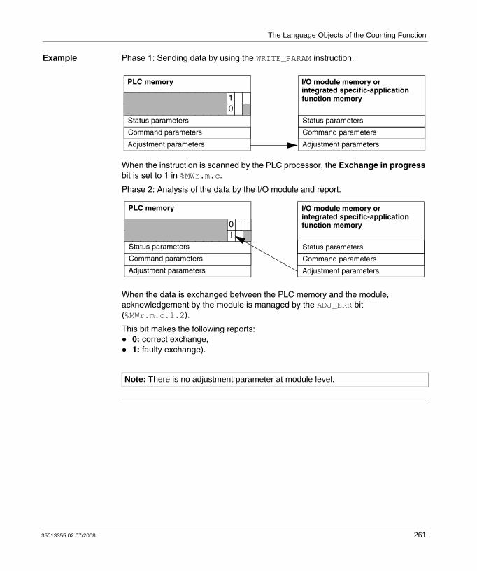
The Language Objects of the Counting Function
Example Phase 1: Sending data by using the WRITE_PARAM instruction.
When the instruction is scanned by the PLC processor, the Exchange in progress bit is set to 1 in %MWr.m.c.
Phase 2: Analysis of the data by the I/O module and report.
When the data is exchanged between the PLC memory and the module, acknowledgement by the module is managed by the ADJ_ERR bit (%MWr.m.c.1.2).
This bit makes the following reports:0: correct exchange,1: faulty exchange).
Note: There is no adjustment parameter at module level.
I/O module memory or integrated specific-application function memory
Status parameters
Command parameters
Adjustment parameters
10
PLC memory
Status parameters
Command parameters
Adjustment parameters
10
Status parameters
Command parameters
Adjustment parameters
PLC memory I/O module memory or integrated specific-application function memory
Status parameters
Command parameters
Adjustment parameters
35013355.02 07/2008 261

The Language Objects of the Counting Function
Execution Indicators for an Explicit Exchange: EXCH_STS
The table below shows the control bits of the explicit exchanges: EXCH_STS (%MWr.m.c.0).
Explicit Exchange Report: EXCH_RPT
The table below shows the report bits: EXCH_RPT (%MWr.m.c.1).
Standard symbol Type Access Meaning Address
STS_IN_PROGR BOOL R Reading of channel status words in progress
%MWr.m.c.0.0
CMD_IN_PROGR BOOL R Command parameters exchange in progress
%MWr.m.c.0.1
ADJ_IN_PROGR BOOL R Adjust parameters exchange in progress
%MWr.m.c.0.2
RECONF_IN_PROGR BOOL R Reconfiguration of the module in progress
%MWr.m.c.0.15
Note: If the module is not present or is disconnected, explicit exchange objects (READ_STS for example) are not sent to the module (STS_IN_PROG (%MWr.m.c.0.0) = 0), but the words are refreshed.
Standard symbol Type Access Meaning Address
STS_ERR BOOL R Error reading channel status words (1 = failure)
%MWr.m.c.1.0
CMD_ERR BOOL R Error during a command parameter exchange (1 = failure)
%MWr.m.c.1.1
ADJ_ERR BOOL R Error during an adjust parameter exchange (1 = failure)
%MWr.m.c.1.2
RECONF_ERR BOOL R Error during reconfiguration of the channel (1 = failure)
%MWr.m.c.1.15
262 35013355.02 07/2008

The Language Objects of the Counting Function
Premium Counting Module Use
The following table describes the steps realised between a Premium Couting Module and the system after a power-on.
If in the begining of your application you use a WRITE_PARAM command, you must wait that the bit %MWr.m.c.0.2 switches to 0.
Step Action
1 Power-on
2 The system send the configuration parameters.
3 The system send the adjust parameters by WRITE_PARAM method.Note: When the operation is finished, the bit %MWr.m.c.0.2 switches to 0.
35013355.02 07/2008 263

The Language Objects of the Counting Function
15.2 Language Objects and IODDT Associated with the Counting Function of the BMX EHC xxxx Modules.
At a Glance
Subject of this Section
This section presents the language objects and IODDTs associated with the counting function of BMX EHC •••• modules.
What's in this Section?
This section contains the following topics:
Topic Page
Details of Implicit Exchange Objects for the T_Unsigned_CPT_BMX and T_Signed_CPT_BMX-types IODDTs
265
Details of Explicit Exchange Objects for the T_Unsigned_CPT_BMX and T_Signed_CPT_BMX-types IODDTs
272
264 35013355.02 07/2008

The Language Objects of the Counting Function
Details of Implicit Exchange Objects for the T_Unsigned_CPT_BMX and T_Signed_CPT_BMX-types IODDTs
At a Glance The tables below present the T_Unsigned_CPT_BMX and T_Signed_CPT_BMX-types IODDTs implicit exchange objects which are applicable to all BMX EHC •••• counting modules.
Counter Value and Sensor Values
The table below presents the various IODDT implicit exchange objects:
Standard symbol Type Access Meaning Language object
COUNTER_CURRENT_VALUE DINT R Current counter value %IDr.m.c.2
CAPT_0_VALUE DINT R Counter value when captured in register 0 %IDr.m.c.4
CAPT_1_VALUE DINT R Counter value when captured in register 1 %IDr.m.c.6
COUNTER_VALUE DINT R Current counter value during event %IDr.m.c.12
CAPT_0_VAL DINT R Capture value 0 %IDr.m.c.14
CAPT_1_VAL DINT R Capture value 1 %IDr.m.c.16
35013355.02 07/2008 265
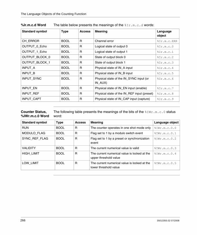
The Language Objects of the Counting Function
%Ir.m.c.d Word The table below presents the meanings of the %Ir.m.c.d words:
Counter Status, %IWr.m.c.0 Word
The following table presents the meanings of the bits of the %IWr.m.c.0 status word:
Standard symbol Type Access Meaning Language object
CH_ERROR BOOL R Channel error %Ir.m.c.ERR
OUTPUT_0_Echo BOOL R Logical state of output 0 %Ir.m.c.0
OUTPUT_1_Echo BOOL R Logical state of output 1 %Ir.m.c.1
OUTPUT_BLOCK_0 BOOL R State of output block 0 %Ir.m.c.2
OUTPUT_BLOCK_1 BOOL R State of output block 1 %Ir.m.c.3
INPUT_A BOOL R Physical state of IN_A input %Ir.m.c.4
INPUT_B BOOL R Physical state of IN_B input %Ir.m.c.5
INPUT_SYNC BOOL R Physical state of the IN_SYNC input (or IN_AUX)
%Ir.m.c.6
INPUT_EN BOOL R Physical state of IN_EN input (enable) %Ir.m.c.7
INPUT_REF BOOL R Physical state of the IN_REF input (preset) %Ir.m.c.8
INPUT_CAPT BOOL R Physical state of IN_CAP input (capture) %Ir.m.c.9
Standard symbol Type Access Meaning Language object
RUN BOOL R The counter operates in one shot mode only %IWr.m.c.0.0
MODULO_FLAG BOOL R Flag set to 1 by a modulo switch event %IWr.m.c.0.1
SYNC_REF_FLAG BOOL R Flag set to 1 by a preset or synchronization event
%IWr.m.c.0.2
VALIDITY BOOL R The current numerical value is valid %IWr.m.c.0.3
HIGH_LIMIT BOOL R The current numerical value is locked at the upper threshold value
%IWr.m.c.0.4
LOW_LIMIT BOOL R The current numerical value is locked at the lower threshold value
%IWr.m.c.0.5
266 35013355.02 07/2008

The Language Objects of the Counting Function
Comparison Status, %IWr.m.c.1 Word
The following table presents the meanings of the bits of the %IWr.m.c.1 status word:
Standard symbol Type Access Meaning Language object
COUNTER_LOW BOOL R Current counter value less than lower threshold (%QDr.m.c.2)
%IWr.m.c.1.0
COUNTER_WIN BOOL R Current counter value is between lower threshold (%QDr.m.c.2) and upper threshold (%QDr.m.c.4)
%IWr.m.c.1.1
COUNTER_HIGH BOOL R Current counter value greater than upper threshold (%QDr.m.c.4)
%IWr.m.c.1.2
CAPT_0_LOW BOOL R Value captured in register 0 is less than lower threshold (%QDr.m.c.2)
%IWr.m.c.1.3
CAPT_0_WIN BOOL R Value captured in register 0 is between lower threshold (%QDr.m.c.2) and upper threshold (%QDr.m.c.4)
%IWr.m.c.1.4
CAPT_0_HIGH BOOL R Value captured in register 0 is greater than upper threshold (%QDr.m.c.4)
%IWr.m.c.1.5
CAPT_1_LOW BOOL R Value captured in register 1 is less than lower threshold (%QDr.m.c.2)
%IWr.m.c.1.6
CAPT_1_WIN BOOL R Value captured in register 1 is between lower threshold (%QDr.m.c.2) and upper threshold (%QDr.m.c.4)
%IWr.m.c.1.7
CAPT_1_HIGH BOOL R Value captured in register 1 is greater than upper threshold (%QDr.m.c.4)
%IWr.m.c.1.8
35013355.02 07/2008 267

The Language Objects of the Counting Function
Event Sources, %IWr.m.c.10 Word
The following table presents the meanings of the bits of the %IWr.m.c.10 word:
Output Thresholds and Frequency
The table below presents the various IODDT implicit exchange objects:
Standard symbol Type Access Meaning Language object
EVT_SOURCES INT R Event sources field %IWr.m.c.10
EVT_RUN BOOL R Event due to start of counter. %IWr.m.c.10.0
EVT_MODULO BOOL R Event due to modulo switch %IWr.m.c.10.1
EVT_SYNC_PRESET BOOL R Event due to synchronization or preset %IWr.m.c.10.2
EVT_COUNTER_LOW BOOL R Event due to counter value being less than lower threshold
%IWr.m.c.10.3
EVT_COUNTER_WINDOW BOOL R Event due to counter value being between the two thresholds
%IWr.m.c.10.4
EVT_COUNTER_HIGH BOOL R Event due to counter value being greater than upper threshold
%IWr.m.c.10.5
EVT_CAPT_0 BOOL R Event due to capture function 0 %IWr.m.c.10.6
EVT_CAPT_1 BOOL R Event due to capture function 1 %IWr.m.c.10.7
EVT_OVERRUN BOOL R Warning: lost event(s) %IWr.m.c.10.8
Standard symbol Type Access Meaning Language object
LOWER_TH_VALUE DINT R/W Lower threshold value %QDr.m.c.2
UPPER_TH_VALUE DINT R/W Upper threshold value %QDr.m.c.4
PWM_FREQUENCY DINT R/W Output frequency value (unit = 0.1 Hz) %QDr.m.c.6
PWM_DUTY INT R/W Duty cycle value of the output frequency (unit = 5%)
%QDr.m.c.8
268 35013355.02 07/2008
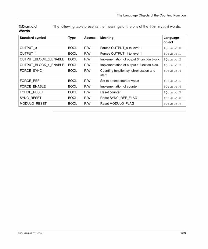
The Language Objects of the Counting Function
%Qr.m.c.d Words
The following table presents the meanings of the bits of the %Qr.m.c.d words:
Standard symbol Type Access Meaning Language object
OUTPUT_0 BOOL R/W Forces OUTPUT_0 to level 1 %Qr.m.c.0
OUTPUT_1 BOOL R/W Forces OUTPUT_1 to level 1 %Qr.m.c.1
OUTPUT_BLOCK_0_ENABLE BOOL R/W Implementation of output 0 function block %Qr.m.c.2
OUTPUT_BLOCK_1_ENABLE BOOL R/W Implementation of output 1 function block %Qr.m.c.3
FORCE_SYNC BOOL R/W Counting function synchronization and start
%Qr.m.c.4
FORCE_REF BOOL R/W Set to preset counter value %Qr.m.c.5
FORCE_ENABLE BOOL R/W Implementation of counter %Qr.m.c.6
FORCE_RESET BOOL R/W Reset counter %Qr.m.c.7
SYNC_RESET BOOL R/W Reset SYNC_REF_FLAG %Qr.m.c.8
MODULO_RESET BOOL R/W Reset MODULO_FLAG %Qr.m.c.9
35013355.02 07/2008 269

The Language Objects of the Counting Function
FUNCTIONS_ENABLING, %QWr.m.c.0 Word
The following table presents the meanings of the bits of the %QWr.m.c.0 words:
Standard symbol Type Access Meaning Language object
VALID_SYNC BOOL R/W Synchronization and start authorization for the counting function via the IN_SYNC input
%QWr.m.c.0.0
VALID_REF BOOL R/W Operation authorization for the internal preset function
%QWr.m.c.0.1
VALID_ENABLE BOOL R/W Authorization of the counter enable via the IN_EN input
%QWr.m.c.0.2
VALID_CAPT_0 BOOL R/W Capture authorization in the capture0 register
%QWr.m.c.0.3
VALID_CAPT_1 BOOL R/W Capture authorization in the capture1 register
%QWr.m.c.0.4
COMPARE_ENABLE BOOL R/W Comparators operation authorization %QWr.m.c.0.5
COMPARE_SUSPEND BOOL R/W Comparator frozen at its last value %QWr.m.c.0.6
270 35013355.02 07/2008
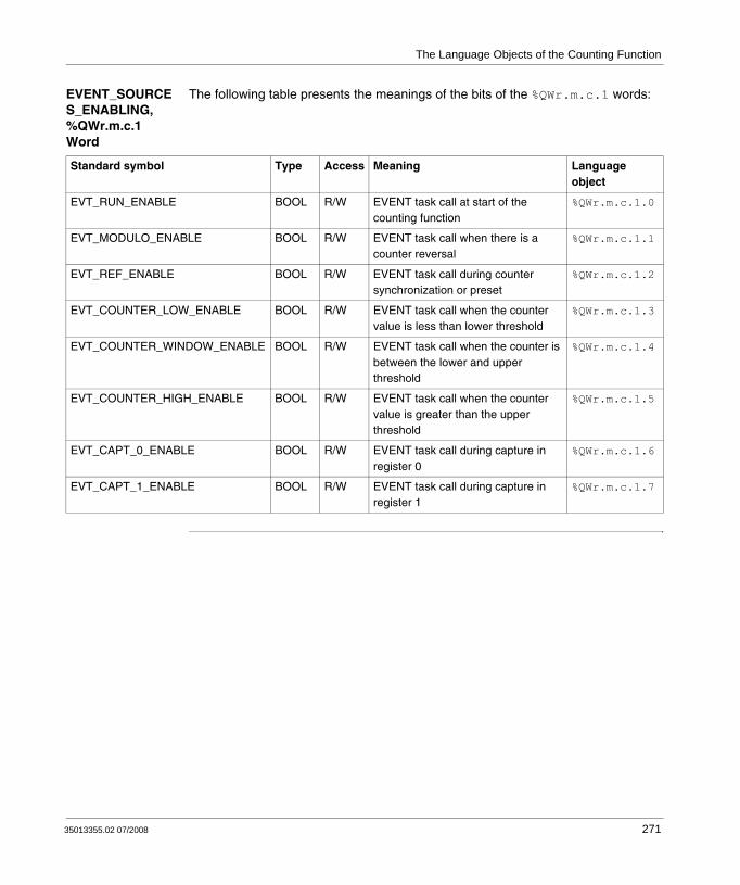
The Language Objects of the Counting Function
EVENT_SOURCES_ENABLING, %QWr.m.c.1 Word
The following table presents the meanings of the bits of the %QWr.m.c.1 words:
Standard symbol Type Access Meaning Language object
EVT_RUN_ENABLE BOOL R/W EVENT task call at start of the counting function
%QWr.m.c.1.0
EVT_MODULO_ENABLE BOOL R/W EVENT task call when there is a counter reversal
%QWr.m.c.1.1
EVT_REF_ENABLE BOOL R/W EVENT task call during counter synchronization or preset
%QWr.m.c.1.2
EVT_COUNTER_LOW_ENABLE BOOL R/W EVENT task call when the counter value is less than lower threshold
%QWr.m.c.1.3
EVT_COUNTER_WINDOW_ENABLE BOOL R/W EVENT task call when the counter is between the lower and upper threshold
%QWr.m.c.1.4
EVT_COUNTER_HIGH_ENABLE BOOL R/W EVENT task call when the counter value is greater than the upper threshold
%QWr.m.c.1.5
EVT_CAPT_0_ENABLE BOOL R/W EVENT task call during capture in register 0
%QWr.m.c.1.6
EVT_CAPT_1_ENABLE BOOL R/W EVENT task call during capture in register 1
%QWr.m.c.1.7
35013355.02 07/2008 271

The Language Objects of the Counting Function
Details of Explicit Exchange Objects for the T_Unsigned_CPT_BMX and T_Signed_CPT_BMX-types IODDTs
At a Glance This section presents the explicit exchange objects for the T_Unsigned_CPT_BMX and T_Signed_CPT_BMX- types IODDTs which are applicable to all BMX EHC •••• counting modules. They includes word type objects whose bits have a specific meaning. These objects are described in detail below.
Sample variable declaration: T_Unsigned_CPT_BMX and T_Signed_CPT_BMX-types IODDT_VAR1.
Preset Values The table below shows the meaning of the status bits.
Exchange Status: EXCH_STS
The table below shows the meaning of channel exchange status bits from the EXCH_STS channel (%MWr.m.c.0).
Note: in general, the meaning of the bits is given for bit status 1.not all bits are used.
Standard symbol Type Access Meaning Language object
MODULO_VALUE DINT R/W Modulo value %MDr.m.c.4
PRESET_VALUE DINT R/W Preset value %MDr.m.c.6
CALIBRATION_FACTOR INT R/W Calibration factor-10% to +10% (unit = 0.1%)
%MWr.m.c.8
SLACK_VAL INT R/W Offset value %MWr.m.c.9
Standard symbol Type Access Meaning Language object
STS_IN_PROG BOOL R Status parameter read in progress %MWr.m.c.0.0
ADJ_IN_PROG BOOL R Adjust parameter exchange in progress %Mwr.m.c.0.2
RECONF_IN_PROG BOOL R Reconfiguration in progress %MWr.m.c.0.15
272 35013355.02 07/2008

The Language Objects of the Counting Function
Channel Report: EXCH_RPT
The following table presents the meanings of the report bits of the EXCH_RPT channel (%MWr.m.c.1).
Channel Fault: CH_FLT
The table below presents the meaning of the fault bits on the CH_FLT channel (%MWr.m.c.2).
Channel Fault: %MWr.m.c.3
The table below presents the meaning of the fault bits on the %MWr.m.c.3 word.
Standard symbol Type Access Meaning Language object
STS_ERR BOOL R Error while reading channel status %MWr.m.c.1.0
ADJ_ERR BOOL R Error while adjusting the channel %Mwr.m.c.1.2
RECONF_ERR BOOL R Error while reconfiguring the channel %MWr.m.c.1.15
Standard symbol Type Access Meaning Language object
EXTERNAL_FLT_INPUTS BOOL R External fault at inputs %MWr.m.c.2.0
EXTERNAL_FLT_OUTPUTS BOOL R External fault at outputs %MWr.m.c.2.1
INTERNAL_FLT BOOL R Internal fault: channel inoperative %MWr.m.c.2.4
CONF_FLT BOOL R Hardware or software configuration fault %MWr.m.c.2.5
COM_FLT BOOL R Bus Communication fault %MWr.m.c.2.6
APPLI_FLT BOOL R Application fault %MWr.m.c.2.7
Standard symbol Type Access Meaning Language object
SENSOR_SUPPLY BOOL R Low input power supply for the sensors %MWr.m.c.3.2
ACTUATOR_SUPPLY_FLT BOOL R Output power supply failure %MWr.m.c.3.3
SHORT_CIRCUIT_OUT_0 BOOL R Short circuit on output 0 %MWr.m.c.3.4
SHORT_CIRCUIT_OUT_1 BOOL R Short circuit on output 1 %MWr.m.c.3.5
35013355.02 07/2008 273

The Language Objects of the Counting Function
15.3 The IODDT Type T_GEN_MOD Applicable to All Modules
Details of the Language Objects of the IODDT of Type T_GEN_MOD
Introduction All the modules of Modicon M340 PLCs have an associated IODDT of type T_GEN_MOD.
Observations In general, the meaning of the bits is given for bit status 1. In specific cases an explanation is given for each status of the bit.
Some bits are not used.
List of Objects The table below presents the objects of the IODDT.
Standard Symbol Type Access Meaning Address
MOD_ERROR BOOL R Module error bit %Ir.m.MOD.ERR
EXCH_STS INT R Module exchange control word %MWr.m.MOD.0
STS_IN_PROGR BOOL R Reading of status words of the module in progress %MWr.m.MOD.0.0
EXCH_RPT INT R Exchange report word %MWr.m.MOD.1
STS_ERR BOOL R Event when reading module status words %MWr.m.MOD.1.0
MOD_FLT INT R Internal error word of the module %MWr.m.MOD.2
MOD_FAIL BOOL R Internal error, module inoperable %MWr.m.MOD.2.0
CH_FLT BOOL R Inoperative channel(s) %MWr.m.MOD.2.1
BLK BOOL R Terminal block incorrectly wired %MWr.m.MOD.2.2
CONF_FLT BOOL R Hardware or software configuration error %MWr.m.MOD.2.5
NO_MOD BOOL R Module missing or inoperative %MWr.m.MOD.2.6
EXT_MOD_FLT BOOL R Internal error word of the module (Fipio extension only)
%MWr.m.MOD.2.7
MOD_FAIL_EXT BOOL R Internal detected fault, module unserviceable (Fipio extension only)
%MWr.m.MOD.2.8
CH_FLT_EXT BOOL R Inoperative channel(s) (Fipio extension only) %MWr.m.MOD.2.9
BLK_EXT BOOL R Terminal block incorrectly wired (Fipio extension only)
%MWr.m.MOD.2.10
CONF_FLT_EXT BOOL R Hardware or software configuration error (Fipio extension only)
%MWr.m.MOD.2.13
NO_MOD_EXT BOOL R Module missing or inoperative (Fipio extension only)
%MWr.m.MOD.2.14
274 35013355.02 07/2008

35013355.02 07/2008
V
Quick Start: Example of Counting Module ImplementationAt a Glance
Overview This part presents an example of implementation of the counting modules.
What's in this Part?
This part contains the following chapters:
Chapter Chapter Name Page
16 Description of the Application 277
17 Installing the Application Using Unity Pro 279
18 Starting the Application 303
275

Example of Counting Module Implementation
276 35013355.02 07/2008

35013355.02 07/2008
16
Description of the ApplicationOverview of the Application
At a Glance The application described in this document is used for sticking labels on boxes.
The boxes are carried on a conveyor. A label is stuck onto the box when the latter passes by the two dedicated points.
A sensor placed below the conveyor detects any new incoming box. The boxes should arrive at constant intervals.
The conveyor motor is fitted with an encoder connected to a counting input module. Any process deflection is monitored and displayed.
The application's control resources are based on an operator screen displaying all box positions, the number of labeled boxes and the deflection monitoring.
277

Description of the application
Illustration This is the application’s final operator screen:
Operating Mode The operating mode is as follows:
A Start button is used to start the labelling process.A Stop button interrupts the labelling process.When the box arrives at the right time, the Box on time indicator lights on.In case of process deflection, the box delay time is displayed. If this time has been too long, a Process deflection indicator lights on.
Start StopSensor
Nb of boxes
Number of labelled boxes
0Box delay time
Process deflection
Deflection monitoring
1st Labelling Point
2nd Labelling Point
Box on time
278 35013355.02 07/2008

35013355.02 07/2008
17
Installing the Application Using Unity ProAt a Gance
Subject of this chapter
This chapter describes the procedure for creating the application described. It shows, in general and in more detail, the steps in creating the different components of the application.
What's in this Chapter?
This chapter contains the following sections:
Section Topic Page
17.1 Presentation of the Solution Used 280
17.2 Developing the Application 283
279

Application using Unity Pro
17.1 Presentation of the Solution Used
At a Glance
Subject of this section
This section presents the solution used to develop the application. It explains the technological choices and gives the application’s creation timeline.
What's in this Section?
This section contains the following topics:
Topic Page
Technological Choices Used 281
Process Using Unity Pro 282
280 35013355.02 07/2008

Application using Unity Pro
Technological Choices Used
At a Glance There are several ways of writing a counter application using Unity Pro. The one proposed, uses the Modulo Loop Counter Mode available in the BMX EHC 0200 counting input module.
Technological Choices
The following table shows the technological choices used for the application.
Objects Choices used
Counter mode Use of the Modulo Loop Counter Mode. This mode counts the encoder input pulses. The modulo value is the defined counting limit. When the counting reaches the modulo value, the counter restarts from 0.A positive transition of the capture signal triggers the count value capture in the capture register and the counter restarts from 0.In this application, the modulo value is the constant interval between boxes and the capture signal is sent by the sensor.The module reflex outputs are triggered when the counting exceeds defined thresholds.
Supervision screen Use of elements from the library and new objects.
Main supervision program This program contains two sections.The first one, which initiates and uses the Modulo Loop Counter Mode functions, is developed using a Structured Text language (ST).
The Application section, which allows operators screen animation, is created in Ladder Diagram (LD) language.
35013355.02 07/2008 281

Application using Unity Pro
Process Using Unity Pro
At a Glance The following logic diagram shows the different steps to follow to create the application. A chronological order must be respected in order to correctly define all of the application elements.
Description Description of the different types:
Launching of Unit Proand
selection of the processor
Configuration of project in
Configuration
Declaration of variables in
Variables & FB instances
Creation of DFBs in
Derived FB Types
Creation of Section in
Programs/Tasks/MAST
Creation of an animation tablein
Animation tables
Creation of an operator screenin
Operator screens
Generation of project, connection to APIand
switch to RUN mode
Creation of Section in
Programs/Events/I/O Events
282 35013355.02 07/2008

Application using Unity Pro
17.2 Developing the Application
At a Glance
Subject of this Section
This section gives a step-by-step description of how to create the application using Unity Pro.
What's in this Section?
This section contains the following topics:
Topic Page
Creating the Project 284
Configuration of the Counting Module 285
Declaration of Variables 288
Creating the Program for Managing the Counter Module 290
Creating the Labelling Program in ST 292
Creating the I/O Event Section in ST 295
Creating a Program in LD for Application Execution 296
Creating an Animation Table 299
Creating the Operator Screen 301
35013355.02 07/2008 283

Application using Unity Pro
Creating the Project
At a Glance Developing an application using Unity Pro involves creating a project associated with a PLC.
Procedure for Creating a Project
The table below shows the procedure for creating the project using Unity Pro.
Note: For more information, see Unity Pro online help (click on ?, then Unity, then Unity Pro, then Operate modes, and Project configuration).
Step Action
1 Launch the Unity Pro software.
2 Click on File then New to select a PLC.
3 Terminate your configuration, insert a BMX EHC 0200 input module Module Selection, p. 285.
4 Confirm with OK.
PLC DescriptionM340
BMX P34 1000BMX P34 2010BMX P34 2020BMX P34 2030
New Project
OK
Cancel
Help
Micro Basic
CPU 340-20 Modbus CANopen
Premium
Version
CPU 340-20 Modbus Ethernet
CPU 340-10 Modbus
CPU 340-20 Ethernet CANopenPremium
01.0001.0001.0001.0001.00
284 35013355.02 07/2008

Application using Unity Pro
Configuration of the Counting Module
At a Glance Developing a counting application involves choosing the right module and appropriate configuration.
Module Selection The table below shows the procedure for selecting the counting input module.
Step Action
1 In the Project browser double-click on Configuration then on 0:Bus X and on 0:BMX XBP ••• (Where 0 is the rack number)
2 In the Bus X window, select a slot (for example slot 1) and double-click
3 Choose the BMX HEC 0200 counting input module
4 Confirm with OK.
Part Number DescriptionBasic Micro local drop
Communication
BMX EMC 0200
New Device
OK
Cancel
Help
2 channel generic counter8 channel generic counter
Analog
BMX EMC 0800Discrete
Topological Address 0.1
Counting
35013355.02 07/2008 285

Application using Unity Pro
Counting Module Configuration
The table below shows the procedure for selecting the counting function and configuring the module reflex outputs.
Step Action
1 In the Bus X window, double-click on the BMX EHC 0200 counting input module
2 Select a channel (for example Counter 0) and click
3 Select the module function Modulo Loop Counter Mode
4 In the Config tab, configure the OutputBlock 0 reflex output with a pulse when the counting is greater than the Lower Threshold (Pulse = greater than LT) and the OutputBlock 1 reflex output with a pulse when the counting is greater than the Upper Threshold (Pulse = greater than UT). Then click on the Event value and select Enable.
5 Click on the Adjust tab and enter the modulo value (for example 50).
2 channel generic counter
Config. Adjust
Function:
Task:Modulo Loop-Coun
BMX EHC 0200
Counter 1Counter 0 - Modulo L
module4_E 0.3: BMX E...
Input A Filter Without0Input B Filter Without1Input Sync Filter Without2Input EN Filter Without3Input Supply Fault General IO Fault4Output Supply Fault General IO Fault5Counting Interface A = Up, B = Down6Scaling Factor 17Synchro Edge Rising edge on SYNC8OutputBlock 0 Pulse = greater than LT9OutputBlock 1 Pulse = greater than UT
ms10
Pulsewidth 0 10ms
11Pulsewidth 1 1012Polarity 0 Polarity +13Polarity 1 Polarity +14Fault Recovery Latched off15Fallback 0 Without16Fallback 1 Without17Fallback Value 018Fallback Value 119
2021
Label Symbol Value Unit
MAST
EnableEvent0Event Number
286 35013355.02 07/2008

Application using Unity Pro
Declaration of I/O objects
The table below shows the procedure for declaring the I/O Derived Variable
Step Action
1 In the BMX EHC 0200 window, click on the BMX EHC 0200 and then on the I/O objects tab
2 Click on the I/O object prefix address %CH then on the Update grid button, the channel address appears in the I/O object grid
3 Click on the line %CH0.1.0 and then enter a channel name in the Prefix for name zone
4 Now click on different Implicit I/O object prefix addresses then Update grid button to see the names and addresses of the implicit I/O objects.
Overview I/O objects
%CH0.1.MOD1%CH0.1.01%Q0.1.02%Q0.1.0.13%Q0.1.0.24%Q0.1.0.35%Q0.1.0.46%Q0.1.0.57%Q0.1.0.68%Q0.1.0.79%Q0.1.0.810%Q0.1.0.911%IW0.1.012%IW0.1.0.113%IW0.1.0.1014%IW0.1.0.1115%QD0.1.0.216%QD0.1.0.417%QD0.1.0.618
Address
Prefixe for name:Type:
Comment:
CreateCreate
Channel:ConfigurationSystemStatusParameterCommandImplicits %I
%Q
%CH
%QW%IW
%MW%MW
%MW%MW
%KW
%QD%ID
%MD%MD
%KD
%QF%IF
%MF%MF
%KF Select all
Unselect all
I/O object
I/O variable creation
Update
Update grid
Filter on usage
WithoutEncoderEncoder.OUTPUTEncoder.OUTPUTEncoder.OUTPUEncoder.OUTPUEncoder.FORCE_Encoder.FORCE_Encoder.FORCEEncoder.FORCE_Encoder.SYNC_REncoder.MODULEncoder.COUNTEncoder.COMPAEncoder.EVT_SO
Encoder.LOWEREncoder.UPPER
Name
Encoder.PWM_F
35013355.02 07/2008 287

Application using Unity Pro
Declaration of Variables
At a Glance All of the variables used in the different sections of the program must be declared.
Undeclared variables cannot be used in the program.
Procedure for Declaring Variables
The table below shows the procedure for declaring application variables.
Variables Used for the Application
The following table shows the details of the variables used in the application.
Note: For more information, see Unity Pro online help (click on ?, then Unity, then Unity Pro, then Operate modes, and Data editor).
Step Action
1 In Project browser / Variables & FB instances, double-click on Elementary variables
2 In the Data editor window, select the box in the Name column and enter a name for your first variable.
3 Now select a Type for this variable.
4 When all your variables are declared, you can close the window.
Variable Type Definition
Run EBOOL Startup request for the labelling process.
Stop EBOOL Stop the labelling process.
Last_Box_late BOOL The process is in deflection.
Nb_Box DINT Number of labelled boxes.
Position_0 BOOL Box at the beginning of the conveyor.
Position_1 BOOL Box with the first label.
Position_2 BOOL Box with the two labels.
First_Labelling_Point DINT Lower Threshold value.
Second_Labelling_Point DINT Upper Threshold value.
Deflection_Parameter DINT Deflection alarm triggering value.
Waiting_First_Part BOOL The first box is waited.
Waiting_Other_Parts BOOL The first box has already passed.
288 35013355.02 07/2008
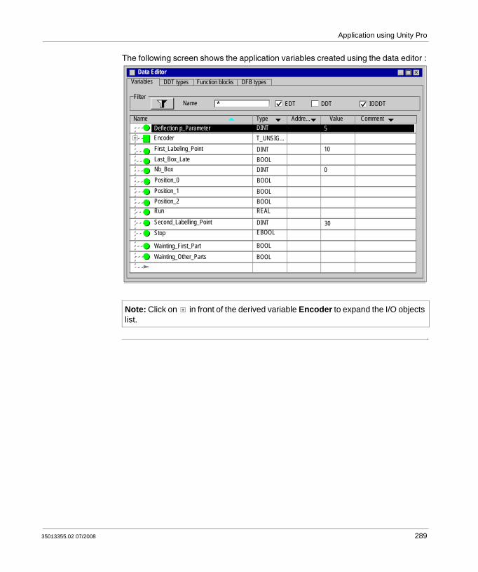
Application using Unity Pro
The following screen shows the application variables created using the data editor :
Note: Click on in front of the derived variable Encoder to expand the I/O objects list.
Variables
EDTNameFilter
DDT IODDT*
Data Editor
Name Type Addre... Comment
Nb_Box
First_Labeling_Point
DINTBOOLDINT
BOOLBOOL
DINTSecond_Labelling_PointStop EBOOL
Position_2
Value
30
T_UNSIG...DINTDeflection p_Parameter
Position_1
Run REAL
Encoder
Last_Box_Late10
0Position_0 BOOL
5
DDT types Function blocks DFB types
Wainting_First_PartWainting_Other_Parts
BOOLBOOL
35013355.02 07/2008 289

Application using Unity Pro
Creating the Program for Managing the Counter Module
At a Glance Two sections are declared in the MAST task:
The Labelling_Program section (See Creating the Labelling Program in ST, p. 292), written in ST, initiates and uses the Modulo Loop Counter Mode functions and I/O objects,The Application section (See Creating a Program in LD for Application Execution, p. 296), written in LD, executes the counting start-up and the operator screen animation.
Process Chart The following screen shows the process chart.
FunctionEnabling
Thresholddefinitions
Processdeflection
Deflection Alarm ON
False
True
Deflection Alarm OFF
290 35013355.02 07/2008

Application using Unity Pro
Description of the Labelling _Program Section
The following table describes the different steps of the process chart.
Step Description
Functions enabling Enables the Modulo Mode functions used in the application.
Threshold definitions The values of the thresholds, on which depend the reflex outputs, are defined in this step.
Process deflection Test if the capture value is greater than the deflection parameter
Deflection Alarm ON If the result of the process deflection test is true, the alarm is ON.
Deflection Alarm OFF If the result of the process deflection test is false, the alarm is OFF.
35013355.02 07/2008 291

Application using Unity Pro
Creating the Labelling Program in ST
At a Glance This section initiates and uses the Modulo Loop Counter Mode functions and objects.
Illustration of the Labelling _Program Section
This section below is part of the MAST task. It has no condiction defined for it so it is permanently executed:
(*Functions Enabling*)
(*Authorizes Input SYNC to synchronize and start the counting function*)
Encoder.VALID_SYNC:=Waiting_First_Part;
IF Waiting_First_Part
THEN nb_box := 0;
END IF;
(*Once the first part has passed below the sensor, the other functions are enabled.*)
IF Waiting_Other_Parts
THEN
(*Authorizes captures into the Capture 0 register*)
Encoder.VALID_CAPT_0:=1;
(*Authorizes comparators to produce its results*)
Encoder.COMPARE_ENABLE:=1;
(*Call Event task when Counter Roll over*)
Encoder.EVT_MODULO_ENABLE:=1;
(*Enable the output block functions*)
Encoder.OUTPUT_BLOCK_0_ENABLE:=1;
Encoder.OUTPUT_BLOCK_1_ENABLE:=1;
ELSE
(*Function disabling when the conveyor is stopped*)
292 35013355.02 07/2008

Application using Unity Pro
Encoder.VALID_CAPT_0:=0
Encoder.COMPARE_ENABLE:=0
Encoder.EVT_MODULO_ENABLE:=0
Encoder.OUTPUT_BLOCK_0_ENABLE:=0
Encoder.OUTPUT_BLOCK_1_ENABLE:=0
END IF
(*Definition of the lower and upper threshold values*)
Encoder.LOWER_TH_VALUE:=First_Labelling_Point;
Encoder.UPPER_TH_VALUE:=Second_Labelling_Point;
(*Process Deflection Watching*)
IF Encoder.CAPT_0_VALUE>deflection_parameter=true
THEN last_box_late:=1; (*Default light set ON*)
ELSE last_box_late:=0; (*Default light set OFF*)
END IF
(*If the next part arrives just in the right time, the green indicator lights on*)
IF Encoder.CAPT_0_VALUE = 0
THEN Last_Box_On_Target :=1 (*Green light set ON*)
ELSE Last_Box_On_Target :=0 (*Green light set OFF*)
END IF
35013355.02 07/2008 293
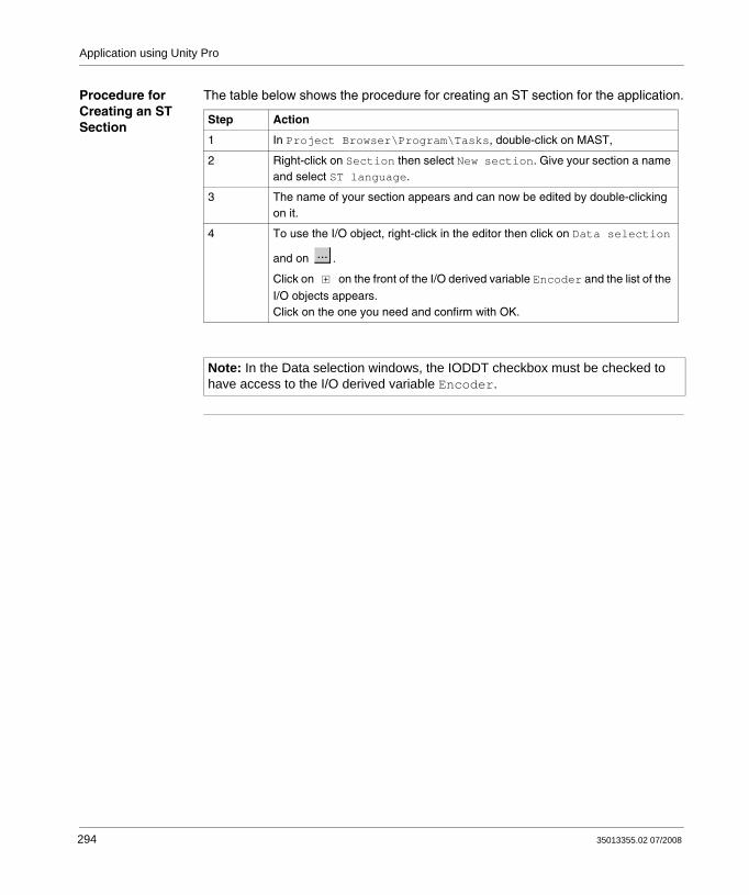
Application using Unity Pro
Procedure for Creating an ST Section
The table below shows the procedure for creating an ST section for the application.
Step Action
1 In Project Browser\Program\Tasks, double-click on MAST,
2 Right-click on Section then select New section. Give your section a name and select ST language.
3 The name of your section appears and can now be edited by double-clicking on it.
4 To use the I/O object, right-click in the editor then click on Data selection
and on .
Click on on the front of the I/O derived variable Encoder and the list of the
I/O objects appears.Click on the one you need and confirm with OK.
Note: In the Data selection windows, the IODDT checkbox must be checked to have access to the I/O derived variable Encoder.
...
294 35013355.02 07/2008

Application using Unity Pro
Creating the I/O Event Section in ST
At a Glance This section is called when the modulo value is reached.
Illustration of the Event Section
The section below is part of the Event task:
(*Number of labelled boxes is incremented at the Modulo Event *)
INC(Nb_Box);
Procedure for Creating an ST Section
The table below shows the procedure for creating an I/O Event.
Step Action
1 In Project Browser\Program\, double-click on Events
2 Right click on I/O Events then select New Event section. Give your section a number, for this example select 0, and then select ST language
3 Confirm with OK and the edition window appears.
35013355.02 07/2008 295

Application using Unity Pro
Creating a Program in LD for Application Execution
At a Glance This section executes the counting start up and the operator screen animation.
296 35013355.02 07/2008
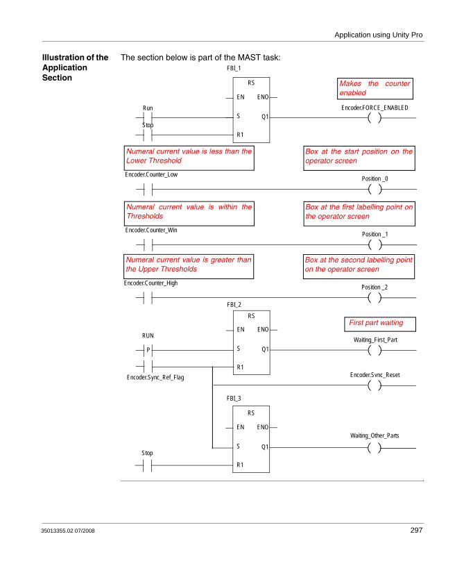
Application using Unity Pro
Illustration of the Application Section
The section below is part of the MAST task: FBI_1
R1
S
EN ENO
Q1
RS
Stop
Run Encoder.FORCE_ENABLED
Makes the counterenabled
Encoder.Counter_Low
Numeral current value is less than theLower Threshold
Position _0
FBI_2
R1
S
EN ENO
Q1
RS
RUN
PWaiting_First_Part
FBI_3
R1
S
EN ENO
Q1
RS
Stop
First part waiting
Box at the start position on theoperator screen
Encoder.Counter_Win
Numeral current value is within theThresholds
Position _1
Box at the first labelling point onthe operator screen
Encoder.Counter_High
Numeral current value is greater thanthe Upper Thresholds
Position _2
Box at the second labelling pointon the operator screen
Encoder.Sync_ResetEncoder.Sync_Ref_Flag
Waiting_Other_Parts
35013355.02 07/2008 297

Application using Unity Pro
Description of the Application Section
The first line is used to commande the counter.The other three lines are used to simulate the different box positions on the conveyor.The last part is used to control the variables which allow the function enabling (See Illustration of the Labelling _Program Section, p. 292When Run switches to ‘1’, Waiting_First_Part is set to ‘1’.A sensor signal triggers the flag Sync_ref_flag which resets Waiting_first_part to '0' and sets Waiting_other_parts to '1'.
Procedure for Creating an LD Section
The table below describes the procedure for creating part of the Application section.
Step Action
1 In Project Browser\Program\Tasks, double-click on MAST.
2 Right click on Section then select New section. Name this section Application, then select the language type LD.The Edit window opens.
3To create the contact Encoder.Sync_Ref_Flag, click on then place it in
the editor. Double-click on this contact then on . The Instance Selection window opens. Validate the Inside structure checkbox and
click on in front of the Encoder variable and select Sync_Ref_Flag in the list. Confirm with OK.
4 To use the RS block you must instantiate it. Right click in the editor then click
on Select data and on . Click on the Function and Function Block Types tab. Click on Libset and select the RS block in the list then confirm with OK and position your block. To link the Encoder.Sync_Ref_Flag contact to the S Rnput of the RS block, align the contact and the input
horizontally, click on and position the link between the contact and the input.
Note: For more information on creating an LD section, see Unity Pro online help (click on ?, then Unity, then Unity Pro, then Operate modes, then Programming and LD editor).
298 35013355.02 07/2008

Application using Unity Pro
Creating an Animation Table
At a glance An animation table is used to monitor the values of variables, and modify and/or force these values. Only those variables declared in Variables & FB instances can be added to the animation table
Procedure for Creating an Animation Table
The table below shows the procedure for creating an animation table.
Note: Note: For more information, consult the Unity Pro online help (click ?, then Unity, then Unity Pro, then Operate modes, then Debugging and adjustment then Viewing and adjusting variables and Animation tables).
Step Action
1 In the Project browser, right click on Animation tables. The edit window opens.
2Click on first cell in the Name column, then on the button, and add the variables you require.
...
35013355.02 07/2008 299

Application using Unity Pro
Animation Table Created for the Application
The following screen shows the animation table used by the application:
Note: The animation table is dynamic only in online mode (display of variable values)
Table
Name Value Type Comment
DINT
Encoder.COMPARE_ENABLE BOOLEncoder.EVT_MODULO_ENABLE BOOL
DINTEncoder.COUNTER_CURRENT_VALUE
DINT
DINTEncoder.UPPER_TH_VALUE
ForceModify
Encoder.LOWER_TH_VALUE
Encoder.CAPT_0_VALUE DINT
First_Labelling_PointSecond_Labelling_Point
Position_1Position_0
Position_2
DINTBOOLBOOLBOOL
Nb_Box DINT
300 35013355.02 07/2008

Application using Unity Pro
Creating the Operator Screen
At a Glance The operator screen is used to animate graphic objects that symbolize the application. These objects can belong to the Unity Pro library, or can be created using the graphic editor.
Illustration on an Operator Screen
The following illustration shows the application operator screen:
Note: For more information, see Unity Pro online help (click on ?, then Unity, then Unity Pro, then Operate modes, and Operator screens).
Note: To animate objects in online mode, you must click on . By clicking on this button, you can validate what is written.
0Start Stop
Sensor
15
Number of labelled boxes
5Box delay time
Process deflection
Deflection monitoring
1st Labelling Point
2nd Labelling Point
Box on time
35013355.02 07/2008 301

Application using Unity Pro
Procedure for Creating an Operator Screen
The table below shows the procedure for creating the Start button.
The table below shows the procedure for inserting and animating the conveyor.
The table below shows the procedure for inserting and animating a display.
Step Action
1 In the Project browser, right click on Operator screens and click on New screen.The operator screen editor appears.
2 Click on the and position the new button on the operator screen. Double click on the button and in the Control tab, select the Run variable by clicking the
button and confirm with OK. Then, enter the button name in the text zone.
Step Action
1 In the Tools menu, select Operator screens Library. Double click on Machine then Conveyor. Select the dynamic conveyor from the runtime screen and Copy (Ctrl+C) then Paste (Ctrl+V) it into the drawing in the operator screen editor.
2 The conveyor is now in your operator screen. You now need a variable to
animate the wheels. Select your conveyor then click on . A line on the wheel is selected. Press enter and the object properties window opens. Select the Animation tab
and enter the concerned variable, by clicking on (in the place of %MW0). In our application, this will be Encoder.INPUT_A, the physical input A state. Confirm with Apply and OK.
3Click on to select the other lines one by one and apply the same procedure.
Note: In the Instance Selection, tick the IODDT checkbox and click on to access the I/O objects list.
Step Action
1 Click on and position it on the operator screen. Double click on the text and select the Animation tab.
2 Tick the Animated Object checkbox, select the concernd variable by cliking on
and confirm with OK.
...
...
Aa
...
302 35013355.02 07/2008
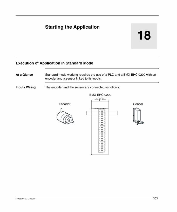
35013355.02 07/2008
18
Starting the ApplicationExecution of Application in Standard Mode
At a Glance Standard mode working requires the use of a PLC and a BMX EHC 0200 with an encoder and a sensor linked to its inputs.
Inputs Wiring The encoder and the sensor are connected as follows:
BMX EHC 0200
Encoder Sensor
303

Starting the Application
The assignment of the 16 pins connector is as follows:
Description:
Pin number Symbol Description
1, 2, 7, 8 24V_SEN 24 VDC output for sensor supply
5, 6, 13, 14 GND_SEN 0 VDC output for sensor supply
15, 16 FE Functionnal ground
3 IN_A Input A
4 IN_SYNC Synchronization input
9 IN_B Input B
10 IN_EN Enable input selected
11 IN_REF Homing input
12 IN_CAP Capture input
1
3
5
7
9
11
13
15
2
4
6
8
10
12
14
16
Encoder Sensor
304 35013355.02 07/2008
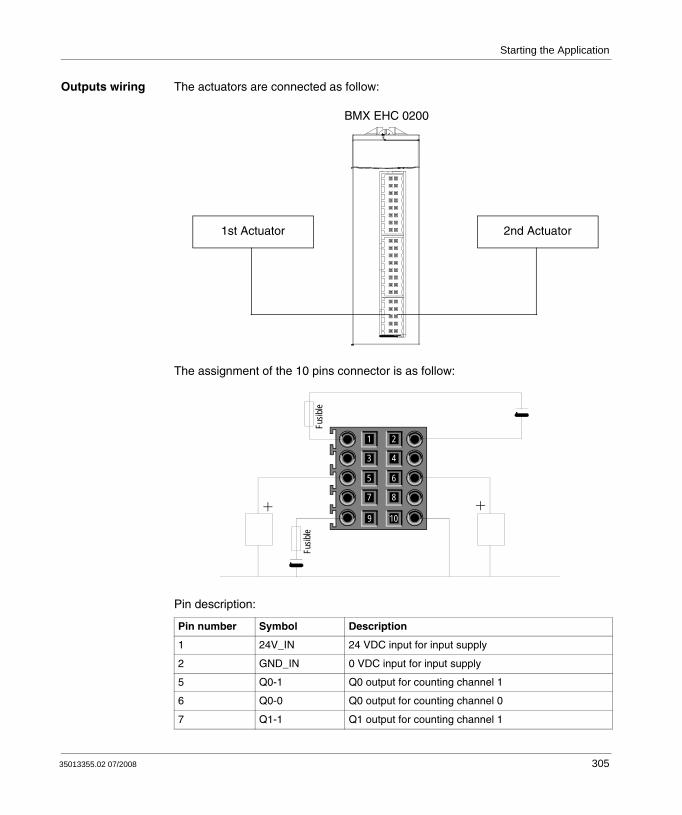
Starting the Application
Outputs wiring The actuators are connected as follow:
The assignment of the 10 pins connector is as follow:
Pin description:
Pin number Symbol Description
1 24V_IN 24 VDC input for input supply
2 GND_IN 0 VDC input for input supply
5 Q0-1 Q0 output for counting channel 1
6 Q0-0 Q0 output for counting channel 0
7 Q1-1 Q1 output for counting channel 1
BMX EHC 0200
1st Actuator 2nd Actuator
1
3
5
7
9
2
4
6
8
10
Fusib
leFu
sible
35013355.02 07/2008 305

Starting the Application
Application Execution
The table below shows the procedure for launching the application in standard mode:
8 Q1-0 Q1 output for counting channel 0
9 24V_OUT 24 VDC input for output supply
10 GND_OUT 0 VDC input for output supply
Pin number Symbol Description
Step Action
1 In the PLC menu, click on Standard Mode,
2 In the Build menu, click on Rebuild All Project. Your project is generated and is ready to be transferred to the PLC. When you generate the project, you will see a results window. If there is an error in the program, Unity Pro indicates its location if you click on the highlighted sequence.
3 In the PLC menu, click on Connection. You are now connected to the PLC.
4 In the PLC menu, click on Transfer project to PLC. The Transfer project to PLC window opens. Click on Transfer. The application is transferred to the PLC.
5 In the PLC, click on Execute. The Execute window opens. Click on OK. The application is now being executed (in RUN mode) on the PLC.
306 35013355.02 07/2008

CBAIndex
BBMXEHC0200, 23BMXEHC0800, 27
Cchannel data structure for all modules
T_GEN_MOD, 274channel data structure for counting modules
T_SIGNED_CPT_BMX, 265, 272T_UNSIGNED_CPT_BMX, 265, 272
configuring, 177
Ddebugging, 223diagnosing, 88, 137dual phase counting, 161
Eevent counting, 104, 150
Ffiltering, 78, 134free large counter, 119frequency mode, 103, 149functions, 76, 132
35013355.02 07/2008
Iinput interface blocks, 77, 133installing, 33, 167
Mmodulo loop counter, 115, 154
Oone shot counter, 111, 152
Pparameter settings, 253period measuring, 106pulse width modulation, 128
Qquick start, 275
Rratio, 109
Ssettings, 215
307

Index
TT_GEN_MOD, 274T_SIGNED_BMX, 265T_SIGNED_CPT_BMX, 272T_UNSIGNED_CPT_BMX, 265, 272terminal blocks
coding, 40connecting, 33installing, 33
Uupcounting and downcounting, 157
Wwiring accessories, 33
308
35013355.02 07/2008