Modes of Loading - mmrl.ucsd.edummrl.ucsd.edu/Courses/SE104/SE104_4_StiffnessLimitedDesign.pdf · 9...
20
1 Materials: engineering, science, processing and design, 2nd edition Copyright (c)2010 Michael Ashby, Hugh Shercliff, David Cebon Materials: engineering, science, processing and design, 2nd edition Copyright (c)2010 Michael Ashby, Hugh Shercliff, David Cebon Modes of Loading (1) – tension (a) (2) – compression (b) (3) – bending (c) (4) – torsion (d) and combinations of them (e) Figure 4.2
Transcript of Modes of Loading - mmrl.ucsd.edummrl.ucsd.edu/Courses/SE104/SE104_4_StiffnessLimitedDesign.pdf · 9...
1
Materials: engineering, science, processing and design, 2nd edition Copyright (c)2010 Michael Ashby, Hugh Shercliff, David Cebon
Materials: engineering, science, processing and design, 2nd edition Copyright (c)2010 Michael Ashby, Hugh Shercliff, David Cebon
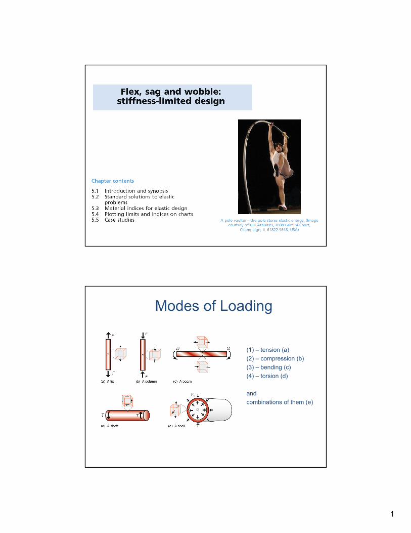
Modes of Loading
(1) – tension (a)
(2) – compression (b)
(3) – bending (c)
(4) – torsion (d)
and
combinations of them (e)
Figure 4.2
2
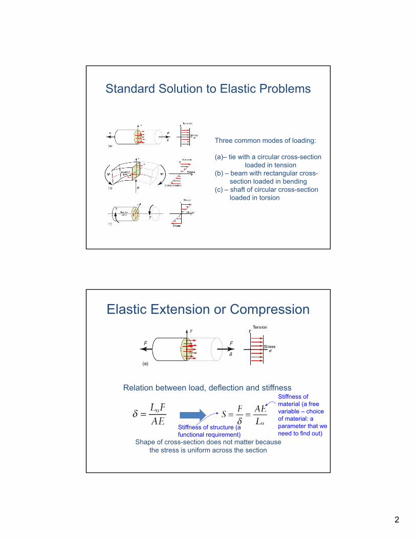
Standard Solution to Elastic Problems
Materials: engineering, science, processing and design, 2nd edition Copyright (c)2010 Michael Ashby, Hugh Shercliff, David Cebon
Figure 5.1
Three common modes of loading:
(a)– tie with a circular cross-sectionloaded in tension
(b) – beam with rectangular cross-section loaded in bending
(c) – shaft of circular cross-sectionloaded in torsion
Elastic Extension or Compression
Materials: engineering, science, processing and design, 2nd edition Copyright (c)2010 Michael Ashby, Hugh Shercliff, David Cebon
Relation between load, deflection and stiffness
Shape of cross-section does not matter becausethe stress is uniform across the section
Stiffness of material (a free variable – choice of material: a parameter that we need to find out)
Stiffness of structure (a functional requirement)
3
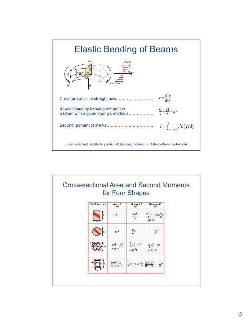
Elastic Bending of Beams
Materials: engineering, science, processing and design, 2nd edition Copyright (c)2010 Michael Ashby, Hugh Shercliff, David Cebon
Curvature of initial straight axis………………………
Stress cause by bending moment in a beam with a given Young’s modulus………………
Second moment of inertia…………………………….
u: displacement parallel to y-axis M: bending moment y: distance from neutral axis
Cross-sectional Area and Second Moments for Four Shapes
Materials: engineering, science, processing and design, 2nd edition Copyright (c)2010 Michael Ashby, Hugh Shercliff, David Cebon
Figure 5.2
4
Materials: engineering, science, processing and design, 2nd edition Copyright (c)2010 Michael Ashby, Hugh Shercliff, David Cebon
Figure 5.3
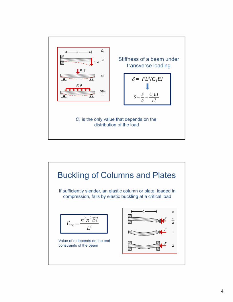
Stiffness of a beam undertransverse loading
C1 is the only value that depends on the distribution of the load
= FL3/C1EI
Buckling of Columns and Plates
Materials: engineering, science, processing and design, 2nd edition Copyright (c)2010 Michael Ashby, Hugh Shercliff, David Cebon
If sufficiently slender, an elastic column or plate, loaded in compression, fails by elastic buckling at a critical load
Figure 5.5
Value of n depends on the endconstraints of the beam
5
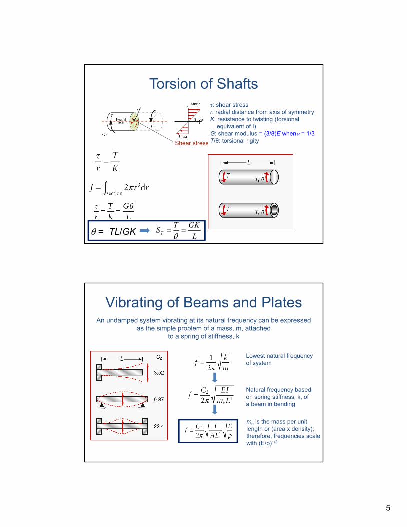
Torsion of Shafts
Materials: engineering, science, processing and design, 2nd edition Copyright (c)2010 Michael Ashby, Hugh Shercliff, David Cebon
Figure 5.4
τ: shear stressr: radial distance from axis of symmetryK: resistance to twisting (torsional
equivalent of I)G: shear modulus = (3/8)E when = 1/3T/θ: torsional rigity
L
GKTST
Shear stress
= TL/GK
Vibrating of Beams and Plates
Materials: engineering, science, processing and design, 2nd edition Copyright (c)2010 Michael Ashby, Hugh Shercliff, David Cebon
Figure 5.6
An undamped system vibrating at its natural frequency can be expressedas the simple problem of a mass, m, attached
to a spring of stiffness, k
Lowest natural frequencyof system
Natural frequency based on spring stiffness, k, of a beam in bending
mo is the mass per unit length or (area x density);therefore, frequencies scalewith (E/ρ)1/2
6
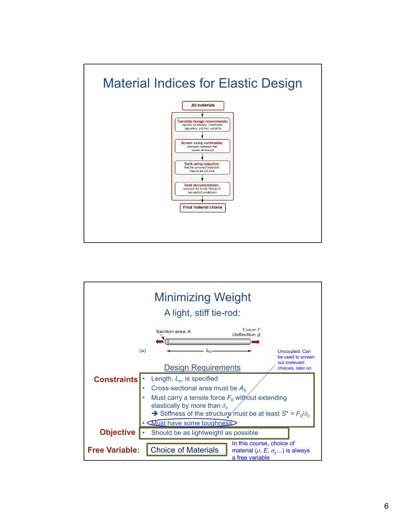
Material Indices for Elastic Design
Materials: engineering, science, processing and design, 2nd edition Copyright (c)2010 Michael Ashby, Hugh Shercliff, David Cebon
Figure 3.6
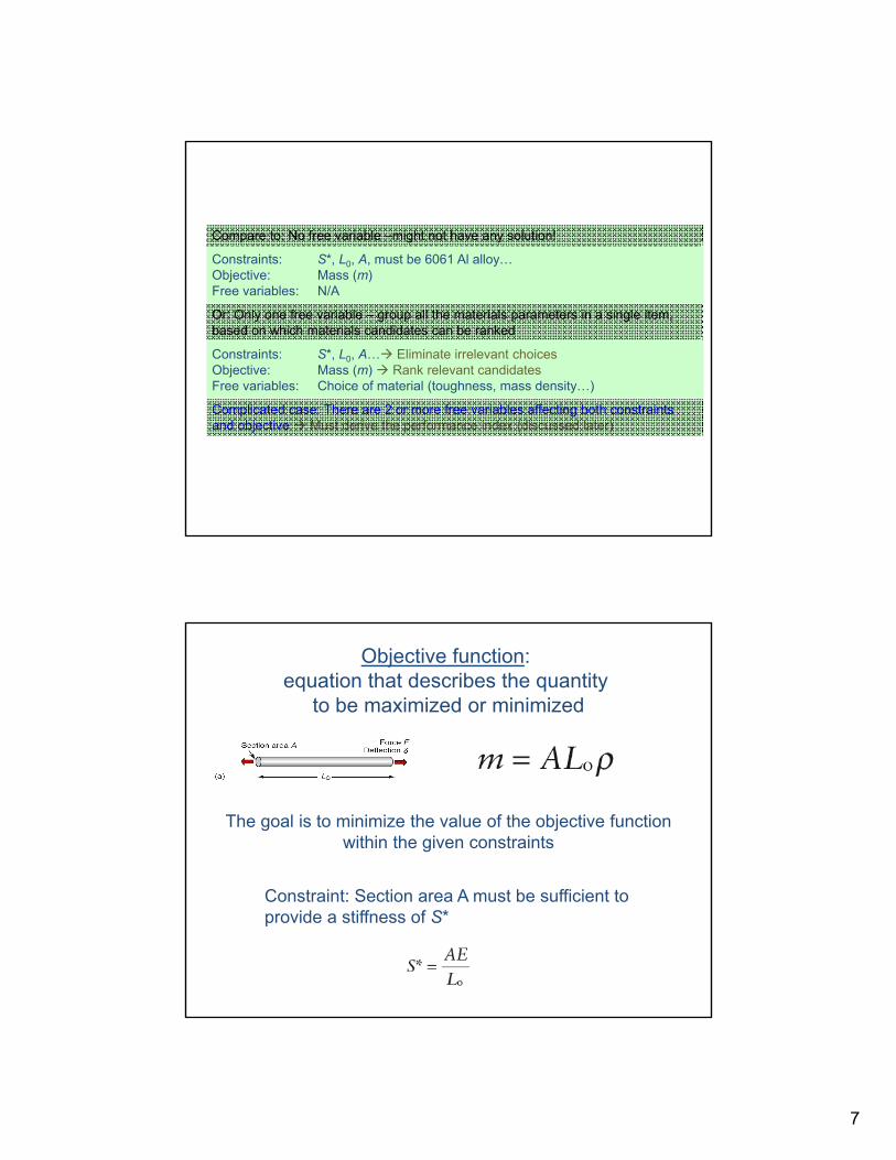
Minimizing Weight
• Length, Lo, is specified
• Cross-sectional area must be A0
• Must carry a tensile force F0 without extending elastically by more than δ0 Stiffness of the structure must be at least S* = F0/δ0
• Must have some toughness
• Should be as lightweight as possible
Materials: engineering, science, processing and design, 2nd edition Copyright (c)2010 Michael Ashby, Hugh Shercliff, David Cebon
A light, stiff tie-rod:
Figure 5.7aDesign Requirements
Constraints
Objective
Free Variable: Choice of Materials In this course, choice of material (, E, y…) is always a free variable
Uncoupled: Can be used to screen out irrelevant choices, later on
7
Materials: engineering, science, processing and design, 2nd edition Copyright (c)2010 Michael Ashby, Hugh Shercliff, David Cebon
Compare to: No free variable –might not have any solution!
Constraints: S*, L0, A, must be 6061 Al alloy…Objective: Mass (m)Free variables: N/A
Or: Only one free variable – group all the materials parameters in a single item, based on which materials candidates can be ranked
Constraints: S*, L0, A… Eliminate irrelevant choicesObjective: Mass (m) Rank relevant candidatesFree variables: Choice of material (toughness, mass density…)
Complicated case: There are 2 or more free variables affecting both constraints and objective Must derive the performance index (discussed later),
Materials: engineering, science, processing and design, 2nd edition Copyright (c)2010 Michael Ashby, Hugh Shercliff, David Cebon
Objective function: equation that describes the quantity
to be maximized or minimized
The goal is to minimize the value of the objective functionwithin the given constraints
Constraint: Section area A must be sufficient to provide a stiffness of S*
8
Materials: engineering, science, processing and design, 2nd edition Copyright (c)2010 Michael Ashby, Hugh Shercliff, David Cebon
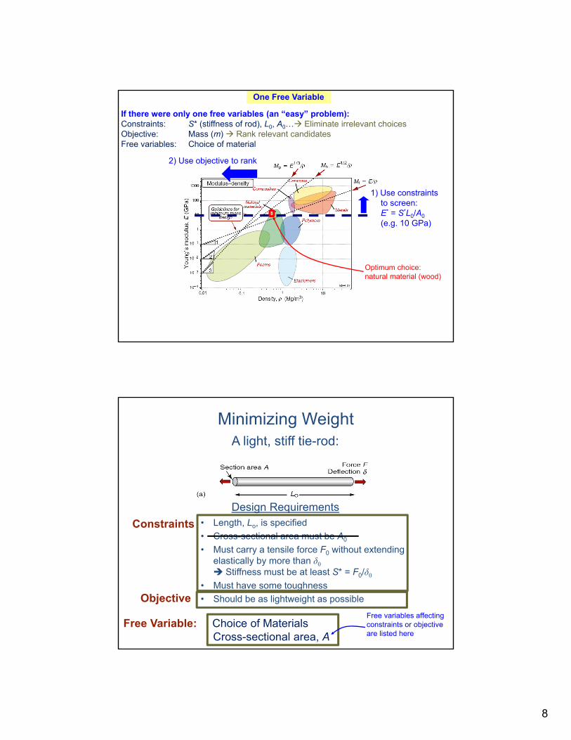
If there were only one free variables (an “easy” problem):Constraints: S* (stiffness of rod), L0, A0… Eliminate irrelevant choicesObjective: Mass (m) Rank relevant candidatesFree variables: Choice of material
Figure 5.10
1) Use constraints to screen: E* = S*L0/A0
(e.g. 10 GPa)
2) Use objective to rank
One Free Variable
Optimum choice: natural material (wood)
Minimizing Weight
• Length, Lo, is specified
• Cross-sectional area must be A0
• Must carry a tensile force F0 without extending elastically by more than δ0 Stiffness must be at least S* = F0/δ0
• Must have some toughness
• Should be as lightweight as possible
Materials: engineering, science, processing and design, 2nd edition Copyright (c)2010 Michael Ashby, Hugh Shercliff, David Cebon
A light, stiff tie-rod:
Figure 5.7aDesign Requirements
Constraints
Objective
Free Variable: Choice of MaterialsCross-sectional area, A
Free variables affecting constraints or objective are listed here
9
Materials: engineering, science, processing and design, 2nd edition Copyright (c)2010 Michael Ashby, Hugh Shercliff, David Cebon
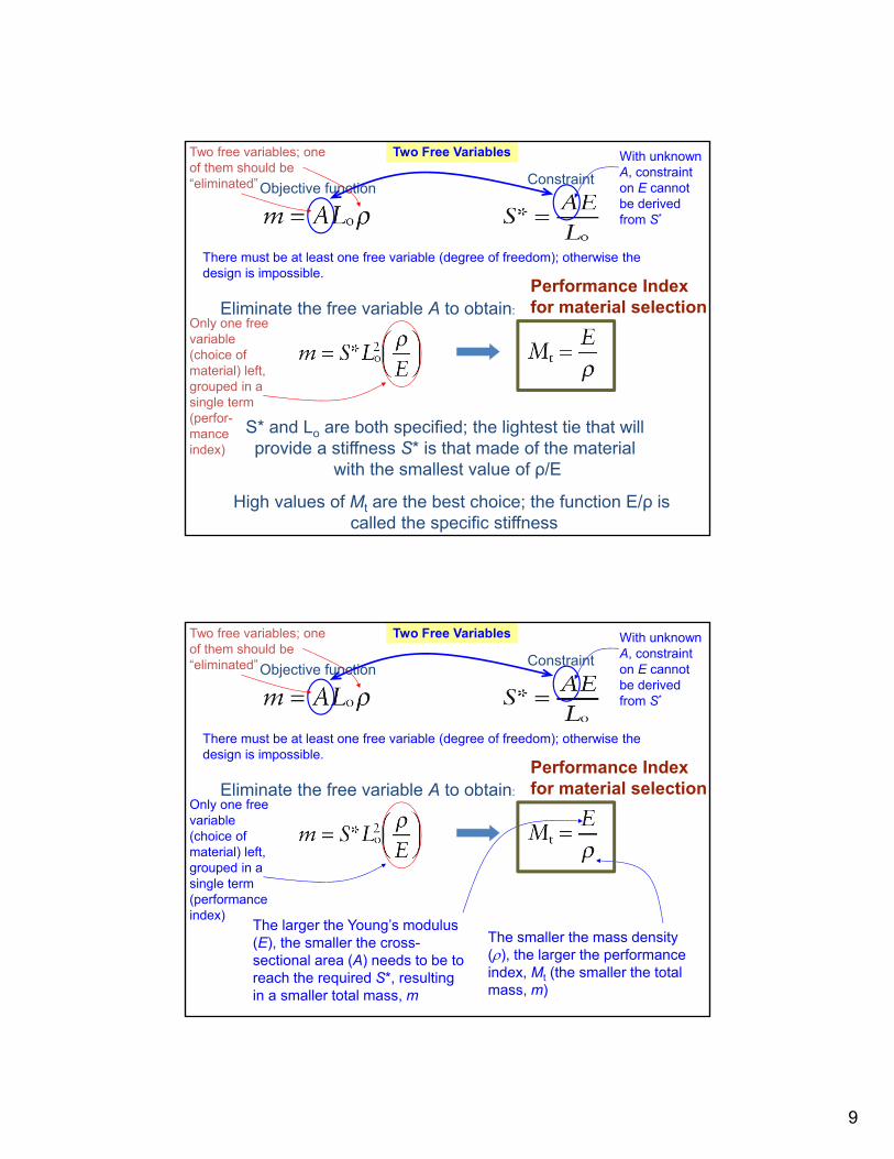
Eliminate the free variable A to obtain:
Objective functionConstraint
S* and Lo are both specified; the lightest tie that will provide a stiffness S* is that made of the material
with the smallest value of ρ/E
There must be at least one free variable (degree of freedom); otherwise the design is impossible.
Two free variables; one of them should be “eliminated”
Only one free variable (choice of material) left, grouped in a single term (perfor-mance index)
Two Free Variables With unknown A, constraint on E cannot be derived from S*
High values of Mt are the best choice; the function E/ρ is called the specific stiffness
Performance Index for material selection
Materials: engineering, science, processing and design, 2nd edition Copyright (c)2010 Michael Ashby, Hugh Shercliff, David Cebon
Eliminate the free variable A to obtain:
Objective functionConstraint
There must be at least one free variable (degree of freedom); otherwise the design is impossible.
Two free variables; one of them should be “eliminated”
Only one free variable (choice of material) left, grouped in a single term (performance index)
Two Free Variables With unknown A, constraint on E cannot be derived from S*
The smaller the mass density (), the larger the performance index, Mt (the smaller the total mass, m)
The larger the Young’s modulus (E), the smaller the cross-sectional area (A) needs to be to reach the required S*, resulting in a smaller total mass, m
Performance Index for material selection
10
Figure 5.10
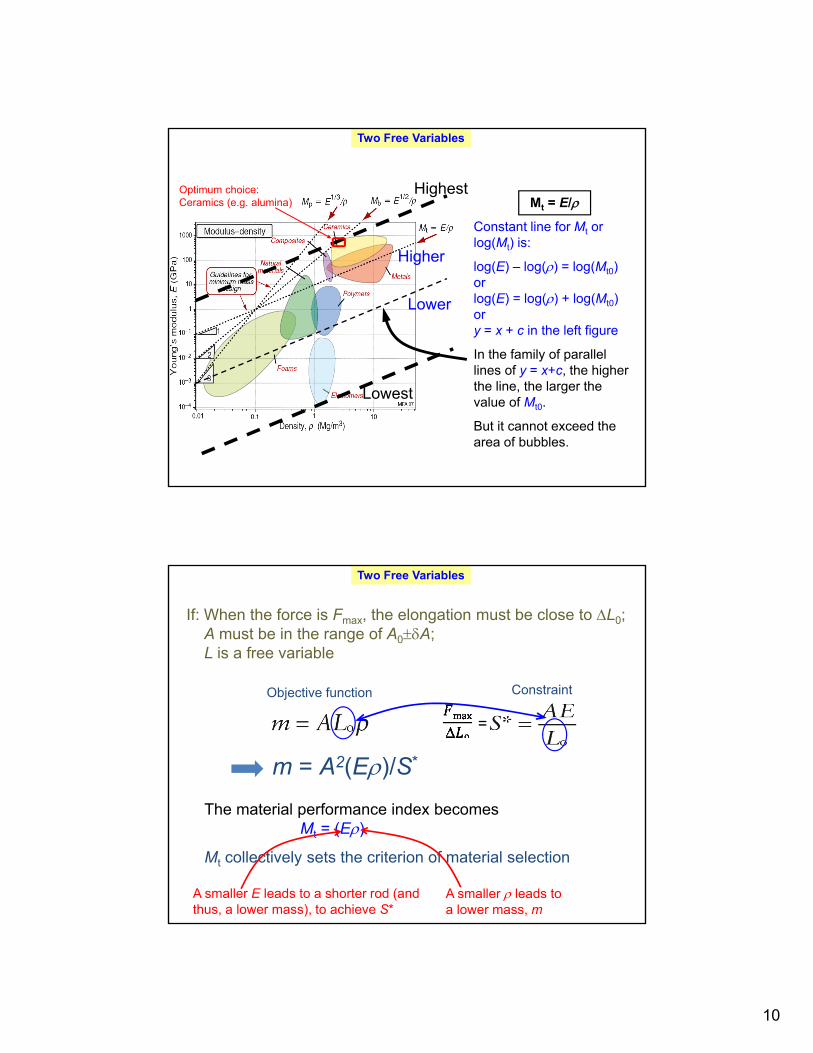
Mt = E/
Constant line for Mt or log(Mt) is:
log(E) – log() = log(Mt0)orlog(E) = log() + log(Mt0)ory = x + c in the left figure
In the family of parallel lines of y = x+c, the higher the line, the larger the value of Mt0.
But it cannot exceed the area of bubbles.
Higher
Lower
Highest
Lowest
Two Free Variables
Optimum choice: Ceramics (e.g. alumina)
Materials: engineering, science, processing and design, 2nd edition Copyright (c)2010 Michael Ashby, Hugh Shercliff, David Cebon
If: When the force is Fmax, the elongation must be close to L0;A must be in the range of A0A; L is a free variable
Objective function Constraint
The material performance index becomesMt = (E)
Mt collectively sets the criterion of material selection
Two Free Variables
A smaller E leads to a shorter rod (and thus, a lower mass), to achieve S*
A smaller leads to a lower mass, m
=
m = A2(E)/S*
11
Materials: engineering, science, processing and design, 2nd edition Copyright (c)2010 Michael Ashby, Hugh Shercliff, David Cebon
Two Free Variables
Figure 5.10
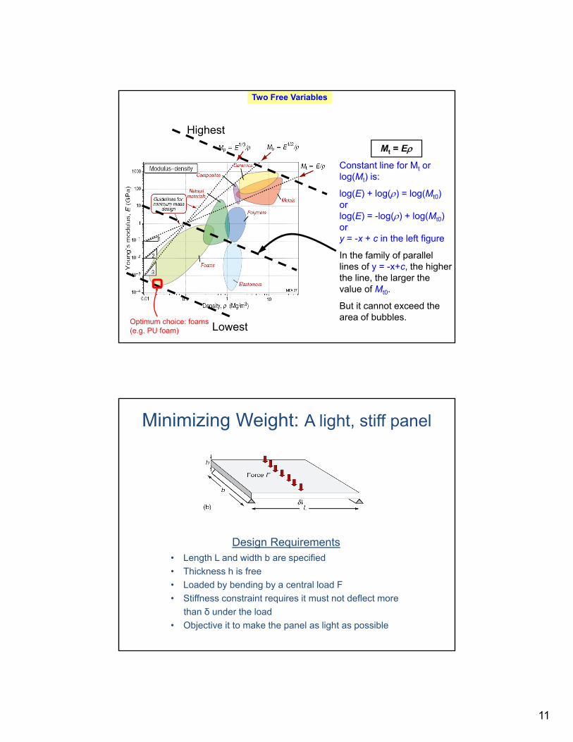
Mt = E
Constant line for Mt or log(Mt) is:
log(E) + log() = log(Mt0)orlog(E) = -log() + log(Mt0)ory = -x + c in the left figure
In the family of parallel lines of y = -x+c, the higher the line, the larger the value of Mt0.
But it cannot exceed the area of bubbles.
Lowest
Highest
Optimum choice: foams (e.g. PU foam)
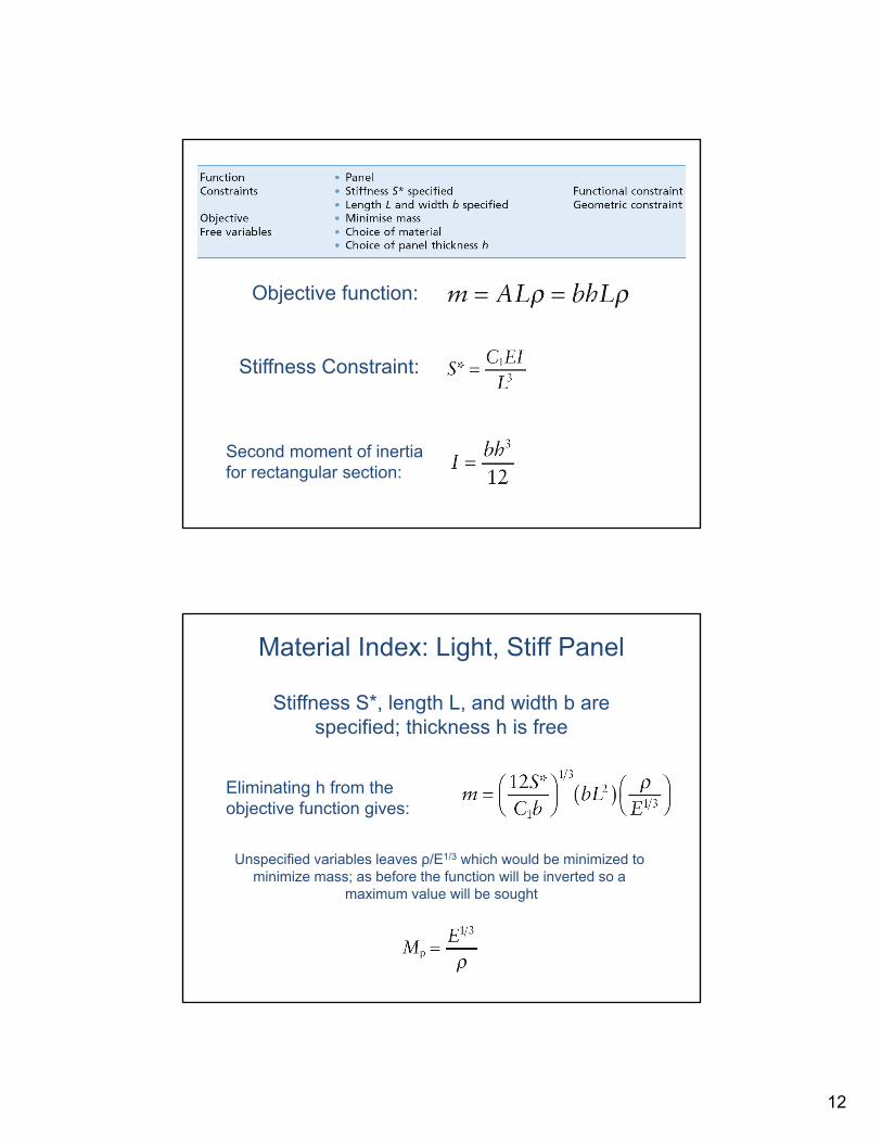
Minimizing Weight: A light, stiff panel
• Length L and width b are specified
• Thickness h is free
• Loaded by bending by a central load F
• Stiffness constraint requires it must not deflect more
than δ under the load
• Objective it to make the panel as light as possible
Materials: engineering, science, processing and design, 2nd edition Copyright (c)2010 Michael Ashby, Hugh Shercliff, David Cebon
Figure 5.7b
Design Requirements
12
Materials: engineering, science, processing and design, 2nd edition Copyright (c)2010 Michael Ashby, Hugh Shercliff, David Cebon
Table 5.2
Objective function:
Stiffness Constraint:
Second moment of inertiafor rectangular section:
Material Index: Light, Stiff Panel
Materials: engineering, science, processing and design, 2nd edition Copyright (c)2010 Michael Ashby, Hugh Shercliff, David Cebon
Stiffness S*, length L, and width b arespecified; thickness h is free
Eliminating h from the objective function gives:
Unspecified variables leaves ρ/E1/3 which would be minimized to minimize mass; as before the function will be inverted so a
maximum value will be sought
13
Materials: engineering, science, processing and design, 2nd edition Copyright (c)2010 Michael Ashby, Hugh Shercliff, David Cebon
Figure 5.10
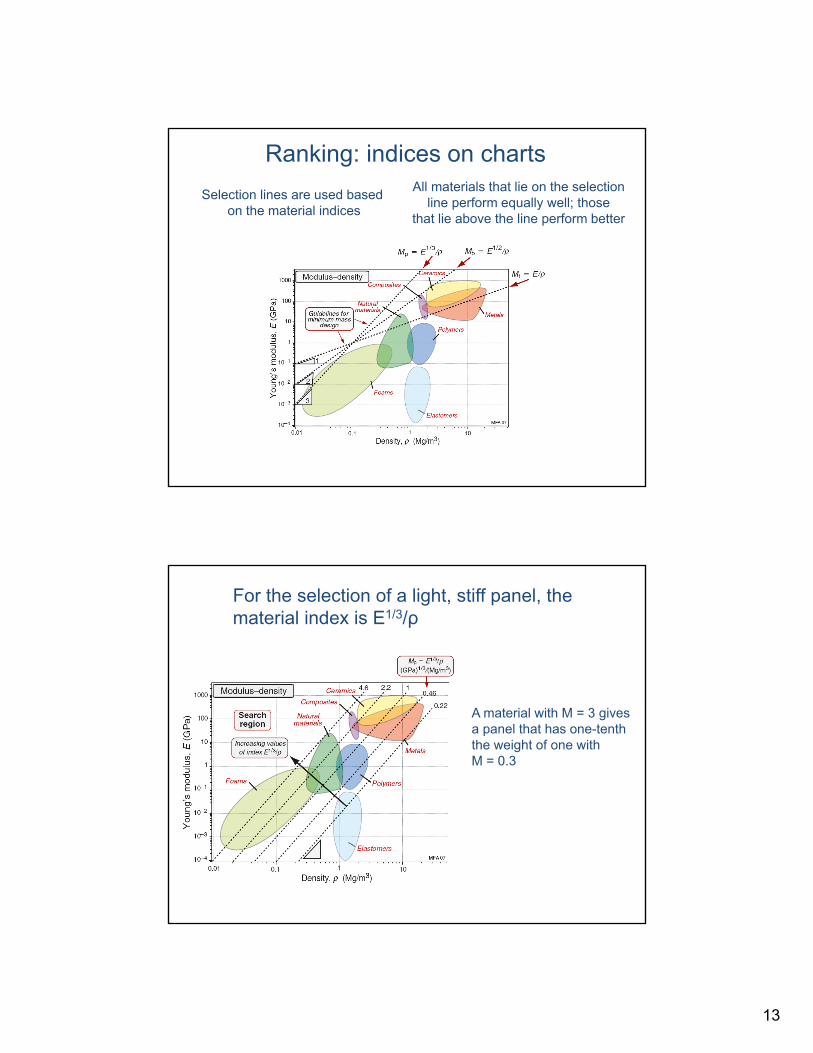
Ranking: indices on charts
Selection lines are used based on the material indices
All materials that lie on the selectionline perform equally well; those
that lie above the line perform better
Materials: engineering, science, processing and design, 2nd edition Copyright (c)2010 Michael Ashby, Hugh Shercliff, David Cebon
Figure 5.11
For the selection of a light, stiff panel, the material index is E1/3/ρ
A material with M = 3 givesa panel that has one-tenththe weight of one with M = 0.3
14
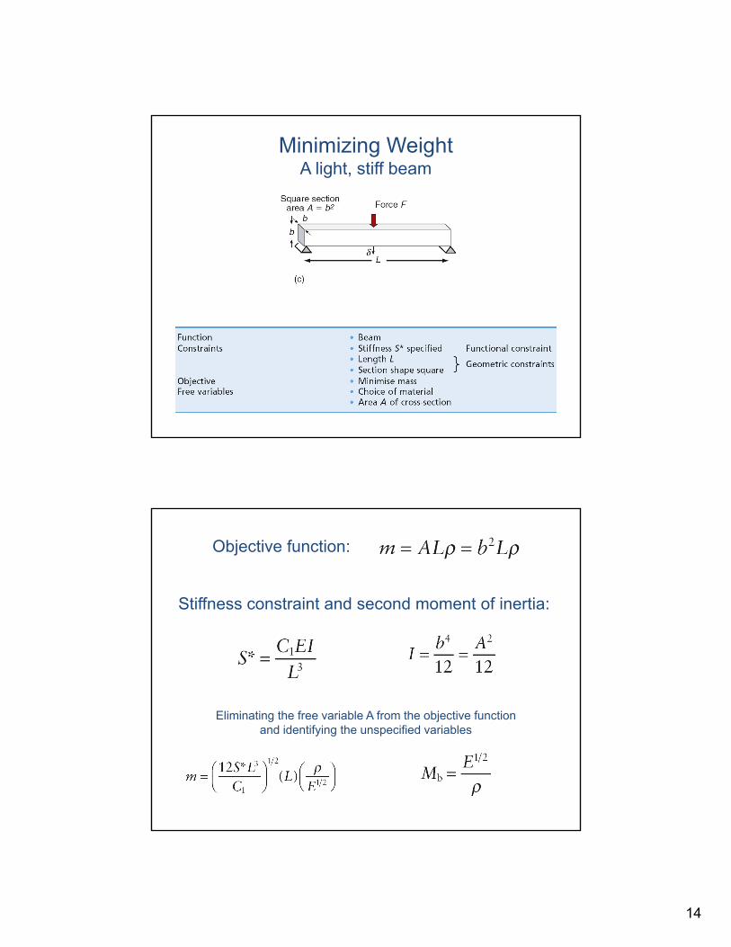
Minimizing WeightA light, stiff beam
Materials: engineering, science, processing and design, 2nd edition Copyright (c)2010 Michael Ashby, Hugh Shercliff, David Cebon
Figure 5.7c
Table 5.3
Materials: engineering, science, processing and design, 2nd edition Copyright (c)2010 Michael Ashby, Hugh Shercliff, David Cebon
Objective function:
Stiffness constraint and second moment of inertia:
Eliminating the free variable A from the objective functionand identifying the unspecified variables
15
Materials: engineering, science, processing and design, 2nd edition Copyright (c)2010 Michael Ashby, Hugh Shercliff, David Cebon
Figure 5.10
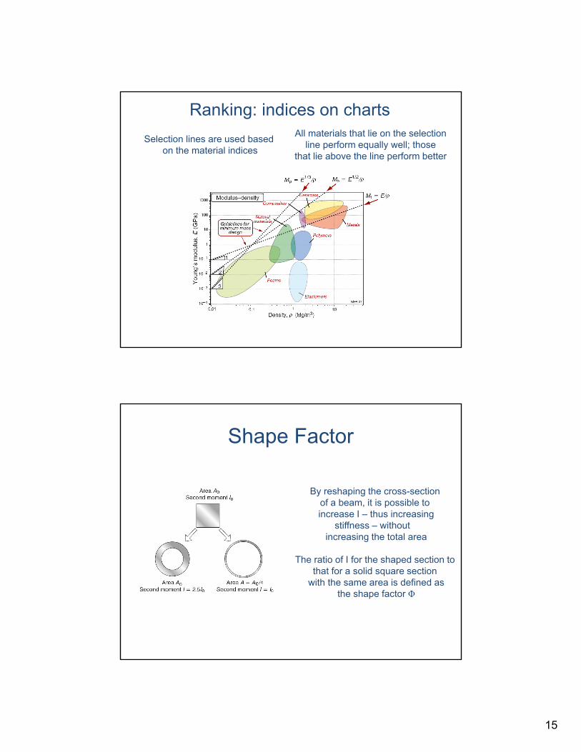
Ranking: indices on charts
Selection lines are used based on the material indices
All materials that lie on the selectionline perform equally well; those
that lie above the line perform better
Shape Factor
Materials: engineering, science, processing and design, 2nd edition Copyright (c)2010 Michael Ashby, Hugh Shercliff, David Cebon
Figure 5.8
By reshaping the cross-section of a beam, it is possible to increase I – thus increasing
stiffness – without increasing the total area
The ratio of I for the shaped section to that for a solid square section
with the same area is defined asthe shape factor Φ
16
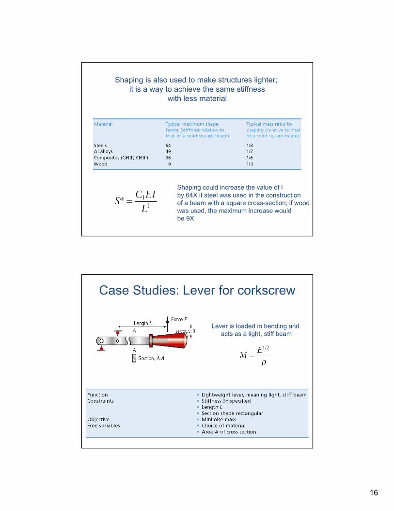
Materials: engineering, science, processing and design, 2nd edition Copyright (c)2010 Michael Ashby, Hugh Shercliff, David Cebon
Shaping is also used to make structures lighter; it is a way to achieve the same stiffness
with less material
Table 5.4
Shaping could increase the value of Iby 64X if steel was used in the constructionof a beam with a square cross-section; if woodwas used, the maximum increase would be 9X
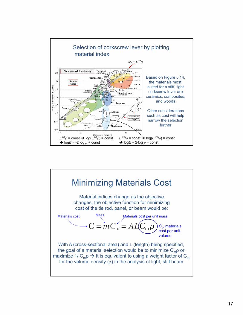
Case Studies: Lever for corkscrew
Materials: engineering, science, processing and design, 2nd edition Copyright (c)2010 Michael Ashby, Hugh Shercliff, David Cebon
Figure 5.12
Table 5.5
Lever is loaded in bending and acts as a light, stiff beam
17
Materials: engineering, science, processing and design, 2nd edition Copyright (c)2010 Michael Ashby, Hugh Shercliff, David Cebon
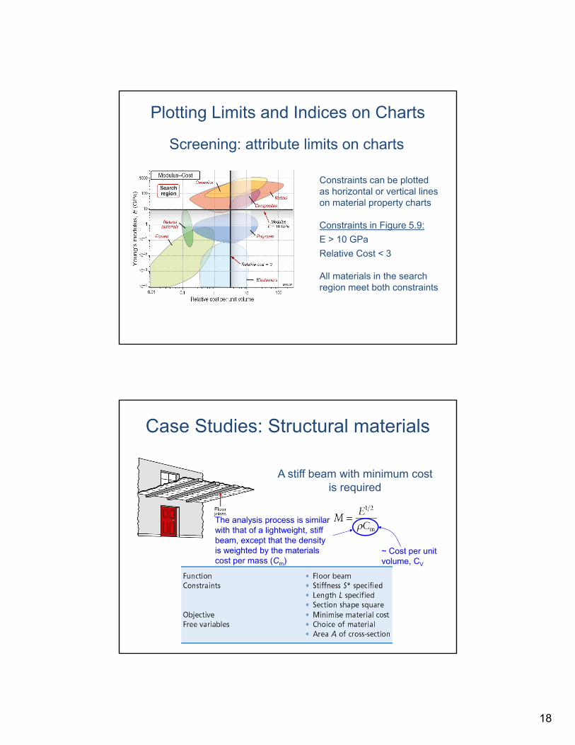
Figure 5.14
Based on Figure 5.14,the materials most
suited for a stiff, lightcorkscrew lever are
ceramics, composites,and woods
Other considerationssuch as cost will helpnarrow the selection
further
Selection of corkscrew lever by plottingmaterial index
E1/2/ = const log(E1/2/) = const logE = 2log + const
E1/2 = const log(E1/2) = const logE = -2log + const
Minimizing Materials Cost
Materials: engineering, science, processing and design, 2nd edition Copyright (c)2010 Michael Ashby, Hugh Shercliff, David Cebon
Material indices change as the objective changes; the objective function for minimizing cost of the tie rod, panel, or beam would be:
With A (cross-sectional area) and L (length) being specified, the goal of a material selection would be to minimize Cmρ or
maximize 1/ Cmρ It is equivalent to using a weight factor of Cm
for the volume density () in the analysis of light, stiff beam.
Materials cost per unit massMaterials cost Mass
CV, materials cost per unit volume
18
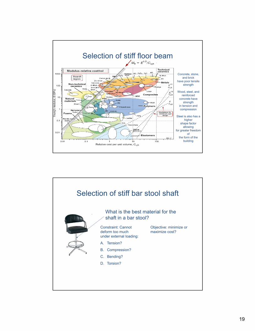
Plotting Limits and Indices on Charts
Materials: engineering, science, processing and design, 2nd edition Copyright (c)2010 Michael Ashby, Hugh Shercliff, David Cebon
Figure 5.9
Screening: attribute limits on charts
Constraints can be plotted as horizontal or vertical lines on material property charts
Constraints in Figure 5.9:
E > 10 GPa
Relative Cost < 3
All materials in the searchregion meet both constraints
Case Studies: Structural materials
Materials: engineering, science, processing and design, 2nd edition Copyright (c)2010 Michael Ashby, Hugh Shercliff, David Cebon
Figure 5.15
A stiff beam with minimum cost is required
Table 5.6
The analysis process is similar with that of a lightweight, stiff beam, except that the density is weighted by the materials cost per mass (Cm)
~ Cost per unit volume, CV
19
Materials: engineering, science, processing and design, 2nd edition Copyright (c)2010 Michael Ashby, Hugh Shercliff, David CebonFigure 5.16
Selection of stiff floor beam
Concrete, stone, and brick
have poor tensile strength
Wood, steel, and reinforced
concrete have strength
in tension and compression
Steel is also has a higher
shape factor allowing
for greater freedom of
the form of the building
Selection of stiff bar stool shaft
What is the best material for the shaft in a bar stool?
Constraint: Cannot deform too much under external loading:
A. Tension?
B. Compression?
C. Bending?
D. Torsion?
Objective: minimize or maximize cost?
20
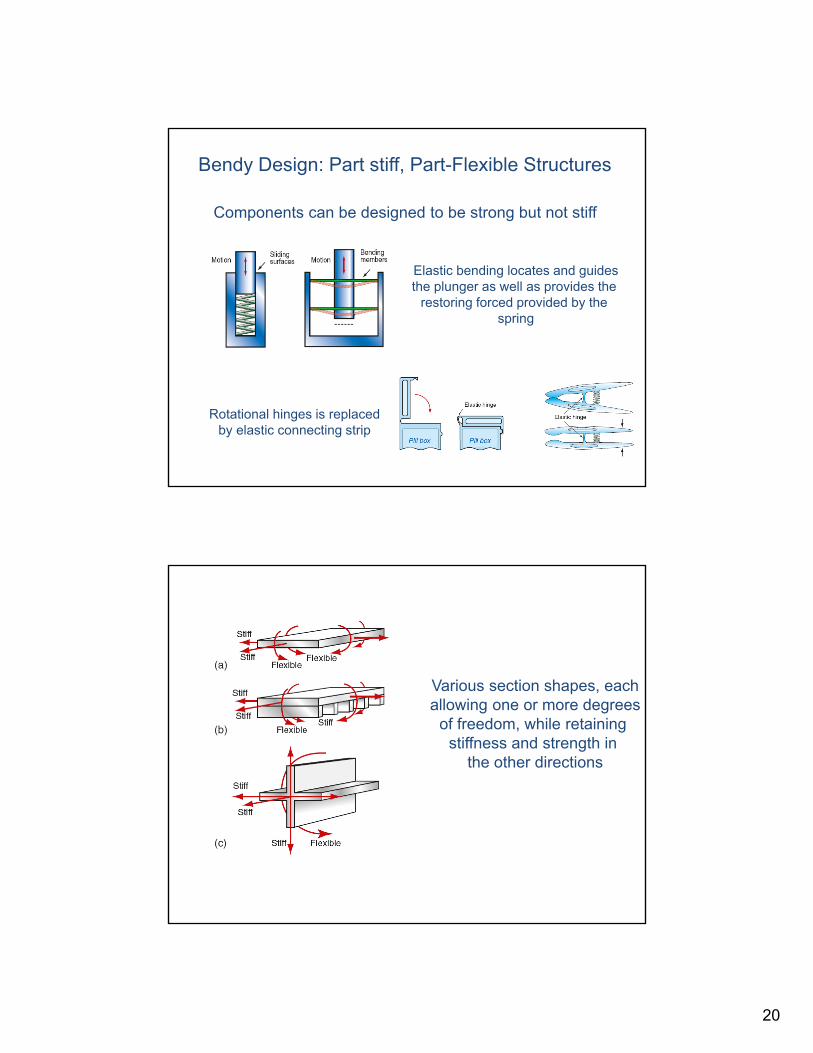
Bendy Design: Part stiff, Part-Flexible Structures
Materials: engineering, science, processing and design, 2nd edition Copyright (c)2010 Michael Ashby, Hugh Shercliff, David Cebon
Figure 5.17
Figure 5.18
Components can be designed to be strong but not stiff
Elastic bending locates and guidesthe plunger as well as provides the
restoring forced provided by the spring
Rotational hinges is replacedby elastic connecting strip
Materials: engineering, science, processing and design, 2nd edition Copyright (c)2010 Michael Ashby, Hugh Shercliff, David Cebon
Figure 5.19
Various section shapes, eachallowing one or more degrees
of freedom, while retaining stiffness and strength in
the other directions