Modernization of the Turning Mechanism of the T -72 Turret · American International Journal of...
15
American International Journal of Contemporary Research Vol. 3 No. 3; March 2013 162 Modernization of the Turning Mechanism of the T -72 Turret Jan Tvarozek Department of Special Technology Alexander Dubček University of Trenčín Pri parku 19, 911 06 Trenčín Slovakia Stanislav Prochazka Department of Weapons and Ammunition University of Defense Kounicova 65, 662 10 Brno Czech Republic Abstract In the process of T-72 tank modernization, reconstruction of the spherical pathway of the turret turning mechanism was carried out. Following the the turret load analysis at the moment of firing and identification of the allowance in the bearing, the turret turning mechanism was rebuilt completely. Analyses show that the cannon muzzle oscillation is caused by several factors. Having analyzed them, specific measures were adopted, such as for instance the elimination of allowance in the spherical pathway seating of the tank turret. Key words: firing power, tank turret turning mechanism, traversing bearing, operating dependability, cyclic loading. Introduction Tanks have been credited as the most universal ground weapon systems. Since a wide array of anti-tank weapons have been invented, the tanks had to be enhanced in the following areas: - firepower, - mobility, - armor. T–72 medium tank is a representative of main battle tanks (MBT). T-72 tanks have been deployed across the world for their good technical specifications and sound properties. T-72 tanks with quality armor have excellent mobility on the road and cross-country at reasonable operating costs. Goals of Modernization The process of modernization was intended to make T-72 tanks fully battleworthy. The main goal was to reduce the shot dispersion, thus to enhance shooting accuracy and service life. The original T-72 weapon system reached merely 50 – 60 per cent of the first-hit probability at the distance of 2,000m in live firing with subcalibre ammunition. The Slovak Armed Forces set out new tactical and technical specifications (TTS) for a modernized T–72 tank. The main task was to improve the first-hit probability at the distance of 2,000m to at least 70 per cent. Having analyzed shootings of the original T–72 tank, we decided to rebuild completely the turret mechanism. In order to meet the tactical and technical specifications prescribed, moments and forces initiating muzzle oscillations had to be decreased to an acceptable level. In addition, allowances in all functional mechanisms and cannon bearings in a cradle had to be eliminated.
Transcript of Modernization of the Turning Mechanism of the T -72 Turret · American International Journal of...

American International Journal of Contemporary Research Vol. 3 No. 3; March 2013
162
Modernization of the Turning Mechanism of the T -72 Turret
Jan Tvarozek
Department of Special Technology
Alexander Dubček University of Trenčín
Pri parku 19, 911 06 Trenčín
Slovakia
Stanislav Prochazka
Department of Weapons and Ammunition
University of Defense
Kounicova 65, 662 10 Brno
Czech Republic
Abstract
In the process of T-72 tank modernization, reconstruction of the spherical pathway of the turret turning
mechanism was carried out. Following the the turret load analysis at the moment of firing and identification of the allowance in the bearing, the turret turning mechanism was rebuilt completely. Analyses show that the cannon
muzzle oscillation is caused by several factors. Having analyzed them, specific measures were adopted, such as
for instance the elimination of allowance in the spherical pathway seating of the tank turret.
Key words: firing power, tank turret turning mechanism, traversing bearing, operating dependability, cyclic loading.
Introduction
Tanks have been credited as the most universal ground weapon systems. Since a wide array of anti-tank weapons have been invented, the tanks had to be enhanced in the following areas:
- firepower,
- mobility,
- armor.
T–72 medium tank is a representative of main battle tanks (MBT). T-72 tanks have been deployed across the
world for their good technical specifications and sound properties. T-72 tanks with quality armor have excellent
mobility on the road and cross-country at reasonable operating costs.
Goals of Modernization
The process of modernization was intended to make T-72 tanks fully battleworthy. The main goal was to reduce the shot dispersion, thus to enhance shooting accuracy and service life. The original T-72 weapon system reached
merely 50 – 60 per cent of the first-hit probability at the distance of 2,000m in live firing with subcalibre
ammunition.
The Slovak Armed Forces set out new tactical and technical specifications (TTS) for a modernized T–72 tank.
The main task was to improve the first-hit probability at the distance of 2,000m to at least 70 per cent.
Having analyzed shootings of the original T–72 tank, we decided to rebuild completely the turret mechanism. In order to meet the tactical and technical specifications prescribed, moments and forces initiating muzzle
oscillations had to be decreased to an acceptable level. In addition, allowances in all functional mechanisms and
cannon bearings in a cradle had to be eliminated.

© Centre for Promoting Ideas, USA www.aijcrnet.com
163
In the process of enhancing the shooting efficiency, construction of mechanical components of the weapon had to
be modified. In addition, the entire stabilizing and fire control systems (including components, such as sight and
aiming systems and sensors) had to be rebuilt.
Due to the complexity of the issue, we address merely the turning mechanism of the turret in the paper. The
elimination of allowance in the turning mechanism was achieved by a complete seating reconstruction of the
traversing bearing. It is to demonstrate that the original bearing of the turret turning mechanism had to be modified in order to meet the tactical and technical specifications set out.
Assessment of the types of bearings in terms of operational dependability
A number of criteria affect operational capacity of ball bearings in the turret turning mechanism. Operational
capacity is determined by constructional and technological parameters of the bearing of the turret turning
mechanism.
The single row ball bearing built in the original T-72 turret (Fig. 1) is a special oblique-angled contact bearing.
The contact angle β plays an important role and is not specified in the available technical documentation. The
angle has an impact on radials, axials, and the so called load capacity bearing torque. Thus, a designer has to select the angle with respect to the overall size of the force in the axial and radial directions as well as the overall
size of the torque acting on the bearing while moving cross-contry and shooting. The specific contact angle β will
change due to tilting of the ring attached to the turret. Tilting is caused by forces acting while driving and shooting and will probably be constantly changing due to wear of the bearing balls and pathways [3], [5].
The graphs a), b) and c) (Fig. 1) show the moment of resistance to rotation, depending on the angle of tilt and the
prestress on the turret ball turning mechanism. The graph a) illustrates the torque development against the turret rotation depending on the inclination, while the bearing is attached with no prestress. The figure shows that
an angle of incline larger than 10° makes the bearing stop rotating and we can conclude that the bearing is
working only with some constraints [7], [8].
Graphs b) and c) show the operational dependability of the bearing when attached with a prestress. Prestress was
measured evenly on the perimeter of the track ball swivel in three points by 120°. The prestress value was 0.5 mm in Figure b) and 1 mm in Figure c). It follows that this type of bearing with prestress does not work properly and
is not dependable.
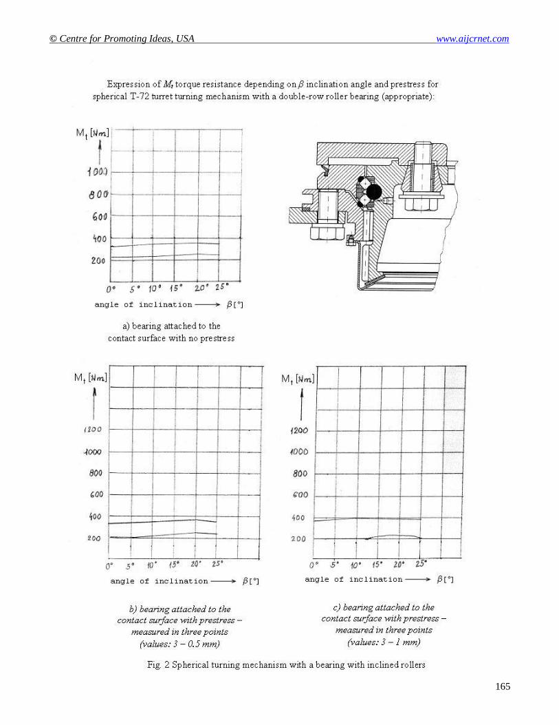
Fig. 2 shows the turning mechanism with a wired double-row bearing with inclined rollers.
As indicated in a), b) and c), the bearing used has sound values in endurance testing and differences are similar under different verification modes. The turning mechanism containing the current bearing were tested equally
with previous turning mechanisms. We maintain that a double-row wire bearing with inclined rollers fits for
proper functioning [11].

American International Journal of Contemporary Research Vol. 3 No. 3; March 2013
164
© Centre for Promoting Ideas, USA www.aijcrnet.com
165

American International Journal of Contemporary Research Vol. 3 No. 3; March 2013
166
Reconstruction of the T–72 Turret Turning Mechanism
Having investigated the turret turning mechanism, it became evident that the current ball bearing cannot meet the new tactical and technical specifications. A ball bearing is a simple compact mechanism needing some allowance.
Formulation of the problem
In line with the technical drawings, the value of the entire original horizontal allowance for the bearing without
any load, ranges from 0.08 to 1.5 mm which can be reached by selecting a suitable pair consisting of an upper and
lower ring.
The following relationship holds true for the total Δ ring allowance:
oba ddd 2 [mm] (1)
The following formula is applied to calculate the horizontal δ distance between the ball so center and sa center or
sb center of the lateral arc of the respective pathway:
4
4
4
aok
ok
ddrrr
[mm] (2)
Contact β angle can be determined from:
180
41arccos
180arccos
okok rrrr [ ° ] (3)
We obtained values for the β contact angle ranging from 21.040° to 74.534° by using allowances for inner and
outer ring pathways. The value of the β contact angle for the given values of the ball cross-section up to 31.75 mm
and the pathway traverse arc radius rk = 17 mm depends on the value of total Δ bearing allowance on a pitch circle
with no load (Fig. 3). With the value of Δ = 4.(rk – ro) = 4.5 mm, the β angle would reach the value of 90° [9], [10].
Fig. 3 illustrates in gray color the specified horizontal allowance range corresponding to allowances identified in
technical drawings for the outer and the inner ring of the bearing and the range of the respective contact angles.
Fig. 3 β contact angle dependence on horizontal allowance of the T–72 tank bearing
a) loţisko je na dosadacej
ploche uchytené bez predpätia
Horizontal allowance of the bearing
[mm]

© Centre for Promoting Ideas, USA www.aijcrnet.com
167
It follows from Figure 1 that a too wide range of bearing allowance cannot meet the new specifications. Bearing
allowances and other irregularities in its seating reach quite high values, and this type of bearing cannot be
mounted with prestress (cf. graphs b) and c) (Fig. 1)). It follows that the bearing cannot function properly since
allowances in the bearing act in a disruptive manner. Therefore, the currently used bearing is not suitable for a modernized T-72 [1], [3].
Proposing a new bearing for the T–72 turret azimuth
Having analyzed various types of bearing swivels, the most suitable for the turret reconstruction in terms of their design and operation are the following:
a) Bearing swivel with a wired bearing designed as a single row four-point contact bearing. When testing a prototype, functional dependability and a new sealing system of the bearing in flowing and still
water were tested.
The turret bearing was subject to the following loads:
Turret weight: 12 t
Recoil: 600,00 kN
Shock (horizontal, vertical): 5 g
The following maximum machining allowances for the linking surfaces of the bearing have been determined:
Bath flatness deviation: 1.2 mm
Turret flatness deviation: 0.3 mm
Following the data, the optimum bearing allowances identified in the prototype ranged from 0.4 to 0.6 mm.
A four-point ball bearing is a simple system requiring bearing allowance in order to work in a dependable manner. Even though the bearing meets all the required standards, it has some constraints due to the precise
electronic systems as well as allowances.
In the process of T-72 modernization, we decided to replace the current bearing with a double-row bearing with
inclined wire rollers (Fig. 2). Thus, requirements for a highly stabilized weapon equipment could be met.
Essential characteristics of the new systems are as follows:
- prestressed pathway with no allowance,
- high inherent toughness and high frequency of resonance,
- steady low resistance against rotation, including irregularities and connecting structure deflections.
The double-row bearing with inclined rollers was subject to the following loads in the course of testing:
Turret weight: 17 t
Recoil: 600,00 kN
Moreover, the turret bearing is equipped with a sealing system.
Analysis of the traversing bearing load at the moment of firing
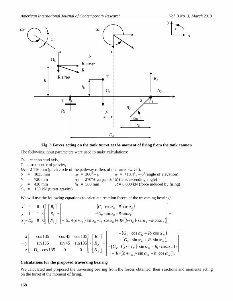
Fig. 3 shows an analysis of forces acting on the ball pathway of the T-72 turret swivel. Following the equations
and calculations based on Fig. 3, we developed a mathematical model expressing the state of the turret load at the
moment of firing. I employed a mathematical model to develop a computing program in "MATLAB" software.
The program can be used to determine the value of all forces and moments acting on the ball trajectory at any point depending on the angle of elevation of the cannon in the range – 6
o to +13.4
o and the tank ascending angle
in the range 15 o.
When comparing the calculations illustrating the development of all R1, R2, N2 and B2 reactions depending on the φ cannon angle of elevation and tank position, it is obvious that the size of reactions is identical for all cases [2],
[4], [6].
American International Journal of Contemporary Research Vol. 3 No. 3; March 2013
168
R2
Fig. 3 Forces acting on the tank turret at the moment of firing from the tank cannon
The following input parameters were used to make calculations:
OK – cannon stud axis,
T – turret center of gravity,
DK = 2 116 mm (pitch circle of the pathway rollers of the turret swivel), b = 1035 mm αR = 360
o – φ φ = +13.4
o , – 6
o (angle of elevation)
h = 720 mm αG = 270o ± φG φG = 15
o (tank ascending angle)
ρ = 430 mm h1 = 500 mm R = 6 000 kN (force induced by firing)
Gv = 150 kN (turret gravity).
We will use the following equations to calculate reaction forces of the traversing bearing:
RRKGGKV
RGV
RGV
K hrbRhrG
RG
RG
N
R
R
Dz
y
x
cossincossin
sinsin
coscos
00
011
100
12
2
1
],cossin
cossin[
,sinsin
,coscos
00135cos
135sin45sin135sin
135cos45cos135cos
1
2
2
1
RRK
GGKV
RGV
RGV
KhrbR
hrG
RG
RG
N
R
R
Dz
y
x
Calculations for the proposed traversing bearing
We calculated and proposed the traversing bearing from the forces obtained, their reactions and moments acting
on the turret at the moment of firing.
x
+ G
Gv h1
T
rk
Ok
R1 B2
R.cos
R
R.sin
b
h
1
2
N2
R
Dk
y
B

© Centre for Promoting Ideas, USA www.aijcrnet.com
169
Computations were elaborated in MS EXCEL in line with relations given in 4 to 11. Input data for the calculation
are listed in Table 2 and the values calculated are listed in Table 3.
The computation was performed for the entire T-72 M2 cannon elevation in the range - 6° to +13.4°.
The values given in Table 2 and the graph in Fig. 4 show the highest load of the bearing in the negative –6° angle of elevation (depression).
SF coefficient ranges from 1.25 at the angle of elevation –6° to 1,48° at the elevation angle +13.4° which indicates that the bearing is of satisfactory static loading capacity under ultimate load conditions.
We have used the following relations to design the traversing bearing:
Maximum load of a single bearing roller is the following:
sin
4
sincos
2max
zd
M
z
F
z
FQ
m
kar [kN] (4)
The sum of the curvature of all rollers and pathway referred to as “the sum of the curvature“:
md
d
d
2cos2
2
[mm] (5)
The axial force component acting on the roller due to the R firing force:
5,110sin va GRF [kN] (6)
The radial component of the force acting on the roller due to the R firing force:
cos RFr [kN] (7)
Tilting moment acting on the bearing due to the R firing force:
sincos bRhRM k [N.m] (8)
The half contact width of the contact area of a rectangle:
el
Qb max335,0 [m] (9)
Hertzian constant stress for the point of contact:
elb
QS
2
4 max
max
[MPa] (10)
Static factor of safety:
2
max
8000
SSF [MPa
-2] (11)
Notation applied:
d – roller diameter as a guide block,
dm – mean diameter of the bearing,
α – angle of contact of the roller, ερ – sum of roller curvatures,
Fa – axial force acting on the roller,
Fr – radial force acting on the roller,

American International Journal of Contemporary Research Vol. 3 No. 3; March 2013
170
R – force coming from the tank cannon firing,
φ – angle of elevation of the cannon,
Gv – centre of gravity of the turret,
Mk – tilting moment acting on the bearing due to the R firing force, h – stud distance in y axis,
b – stud distance in x axis to the center of the bearing pathway,
Qmax – maximum load per roller, z – number of rolling elements,
b – half contact width of the contact area of a rectangle,
le – effective roller length, Smax – Hertzian contact stress,
SF – static factor of safety.
Table 1 Input data to compute and design the traversing bearing
α = 45o contact angle of rollers
z = 458 number of elements in a row
dm = 2116 mm bearing pitch diameter
d = 12 mm roller diameter
le = 8 mm effective roller length
ερ = 0,167338 sum of roller curvatures
Table 2 Calculated values determining the traversing bearing load
i β Fa Fr Mk Qmax B Smax SF
[ ° ] [N] [N] [N.mm] [N] [mm] [MPa] [ – ]
0 -6.00 6.05E+05 5.97E+06 4.95E+09 67 585 0.753 7 145 1.25
1 -5.03 3.01E+05 5.98E+06 4.85E+09 66 138 0.745 7 068 1.28
2 -4.06 2.00E+05 5.98E+06 4.75E+09 65 297 0.740 7 023 1.30
3 -3.09 9.84E+04 5.99E+06 4.65E+09 64 437 0.735 6 977 1.31
4 -2.12 3.04E+03 6.00E+06 4.55E+09 63 577 0.730 6 930 1.33
5 -1.15 1.05E+05 6.00E+06 4.44E+09 63 308 0.729 6 915 1.34
6 -0.18 2.06E+05 6.00E+06 4.34E+09 63 020 0.727 6 900 1.34
7 0.79 3.08E+05 6.00E+06 4.23E+09 62 714 0.725 6 883 1.35
8 1.76 4.09E+05 6.00E+06 4.13E+09 62 391 0.723 6 865 1.36
9 2.73 5.11E+05 5.99E+06 4.02E+09 62 050 0.721 6 846 1.37
10 3.70 6.12E+05 5.99E+06 3.91E+09 61 691 0.719 6 827 1.37
11 4.67 7.13E+05 5.98E+06 3.80E+09 61 315 0.717 6 806 1.38
12 5.64 8.15E+05 5.97E+06 3.69E+09 60 921 0.715 6 784 1.39
13 6.61 9.16E+05 5.96E+06 3.58E+09 60 511 0.712 6 761 1.40
14 7.58 1.02E+06 5.95E+06 3.46E+09 60 083 0.710 6 737 1.41
15 8.55 1.12E+06 5.93E+06 3.35E+09 59 638 0.707 6 712 1.42
16 9.52 1.22E+06 5.92E+06 3.23E+09 59 176 0.704 6 686 1.43
17 10.49 1.32E+06 5.90E+06 3.12E+09 58 697 0.701 6 659 1.44
18 11.46 1.42E+06 5.88E+06 3.00E+09 58 202 0.699 6 631 1.46
19 12.43 1.52E+06 5.86E+06 2.88E+09 57 690 0.695 6 601 1.47
20 13.40 1.62E+06 5.84E+06 2.76E+09 57 162 0.692 6 571 1.48

© Centre for Promoting Ideas, USA www.aijcrnet.com
171
Fig. 4 Dependence of the contact pressure on the angle of elevation of the cannon
Testing the selected bearing for the T–72 turret turning mechanism
As a part of the turret swivel reconstruction, we measured turning resistance in five turret bearings by using the
defined prestresses of the inner and outer rings. We screwed the bearings to a simulated interconnecting structure
of stiffness similar to that prevalently used in practice.
The bearing was screwed to the structure as shown in Figure 5. The tightening torque of the M16 clamping screw
holes was 250 N.m. The outer ring was screwed to the testing device by means of a connecting plate. The first plate being loaded was screwed to the inner ring. While testing the resistance against rotation, the outer ring and
the plate were rotating. The inner ring was held by a lever arm. A force sensor was mounted between the arm and
support of the testing device. Rotation resistance was measured by means of the force sensor, frequency amplifier
and recorder. Simulation device and testing of bearings are shown in Fig. 5.
In the course of testing, load was induced by the corresponding loading plate. The values were following:
Fa = 130 kN,
Mk = 26 kNm.
The moment was created by two eccentric loading plates.
Testing revolutions: number of revolutions 1, turning speed 1 min-1
in both directions.
Fastening options to test bearings:
The following two standard fastening tests were carried out with all five bearings:
– First option:
Turret: 2 x 0.8 mm
Tub: 1 x 0.6 mm
– Second option:
Turret: 2 x 0.3 mm
Tub: 1 x 1.2 mm
An additional fastening test was performed with the bearing No. 4. Three additional fastening tests were carried
out with the bearing No. 5:
– Additional fastening test:
Turret: 2 x 0.3 mm
Tub: 1 x 1.2 mm

American International Journal of Contemporary Research Vol. 3 No. 3; March 2013
172
– Bearings No. 4 and 5:
Turret: 2 x 0.3 mm
Tub: 1 x 0.3 mm
– Bearing No. 5:
Leveled turret
Tub: 3 x 3.0 mm
Irregularities at the lower and upper fastening surface were simulated in bearing No. 5 by inserting suitable plates.
Developments of all fastenings are illustrated and the test results of all bearings are listed in Table 3. The table
lists the torque resistance depending on the state of prestress.
Fig. 5 Testing device for the T–72 M2 bearing
Table 3 Results of testing the bearings No. 1 to No. 5, torque resistance depending on the bearing assembly
prestress
1 2 3 4 5
Turret
Tub
2 x 0.8 mm
1 x 0.6 mm
2 x 0.8 mm
1 x 1.2 mm
2 x 0.3 mm
1 x 1.2 mm
2 x 0.3 mm
1 x 1.2 mm
–
3 x 3,. mm
Serial No. Torque Mk [N.m]
1 405 ± 155 520 ± 195 – – –
2 480 ± 100 515 ± 165 – – –
3 420 ± 150 560 ± 140 – – –
4 405 ± 135 480 ± 185 470 ± 180 – –
5 390 ± 90 410 ± 130 380 ± 80 385 ± 80 650 ± 190

© Centre for Promoting Ideas, USA www.aijcrnet.com
173
Table 4 Determination of Mt turret resistance moments with respect to its axis of rotation
Product No. P3 L = 6,15 m
Turret
position Azimuth
Measurement number
Turret on the right with unloaded
ammunition
Turret on the left with unloaded
ammunition Requirements TP [N.m] R1
clockwise [N]
Mt
[N.m] Assessment
R2
counterclockwise [N]
Mt [N.m] Assessment
30-00
1 180 1,099.8
0 satisfactory
190
1,160.90 satisfac
tory 1471 2 180 190
3 182 190
22-50
1 180 1,099.8
0 satisfactory
180
1,099.80 satisfac
tory 1471 2 180 180
3 180 180
15-00
1 180 1,099.8
0 satisfactory
185
1,130.35 satisfac
tory 1471 2 180 185
3 180 185
7-50
1 170 1,038.70
satisfactory
170
1,038.70 satisfactory
1471 2 170 170
3 172 170
00-00
1 175 1,069.25
satisfactory
150
916.50 satisfactory
1471 2 175 150
3 175 150
52-50
1 200 1,222.0
0 satisfactory
140
855.40 satisfac
tory 1471 2 200 140
3 200 140
45-00
1 190 1,160.9
0 satisfactory
150
916.50 satisfac
tory 1471 2 190 150
3 190 150
37-50
1 160
977.60 satisfactory
170
1,038.70 satisfac
tory 1471 2 160 170
3 160 170
30,00
1 150
916.50 satisfactory
170
1,038.70 satisfactory
1471 2 150 170
3 150 170

American International Journal of Contemporary Research Vol. 3 No. 3; March 2013
174
Table 5 Testing the new reconstructed spherical pathway of the T-72 M2 turret swivel
Test Procedure Requirements Results
Water tightness test
Water level in a testing stand min. 90 mm, duration 5 – 10 min.
Water leak not allowed. Satisfactory
Resistance
moment of the
turret turning
Turret positioned on the horizontal
surface with an accuracy of 30´ to its
axis of rotation, traverse drive hydro
motor switched on/ switched off.
Resistance moment of the turret with
the traverse drive hydro motor switched
on must be max. 1,226 N.m (125 kpm),
with the traverse drive hydro motor
switched off max. 687 N.m
Satisfactory
Force to
spherical
pathway rotation
Testing must be carried out with
a load of 12t (turret) with the center
of gravity at the distance 300 ± 40
mm from the center of rotation of the
spherical pathway. When testing
torque, spherical pathway rewind
max. by 2 compete revolutions.
Torque max. 550 N.m. Satisfactory
Force on the
handle of the
azimuth hand
wheel
In the horizontal position, turn the turret by a full revolution to the right
and left. Rotation must be smooth,
with no noticeable force changes on
the hand wheel handle. Converting is
allowed mechanically in four
opposite points with the force
condition on the hand wheel.
Value of size on the handle max. 58.8
N.
Satisfactory
Testing tightness
of the fighting
compartment
excess pressure
Create excess pressure of 0.5 MPa in
the fighting compartment.
In the area of spherical pathway, no
leakage of pressure shall be recorded. Satisfactory
Measuring
allowance on the
spherical
pathway
Turret inclination 15°. Allowance
should be measured in longitudinal and transverse direction of the turret
(at least 4 measurements) along the
circle of the spherical pathway when
turning both sides. Check maximum
allowance at turning the turret by
180°, in transverse direction
measurement with the deviation from
the transverse axis by ± 30° is
allowed. Do not check allowance in
other points on the circle.
Satisfactory
Conclusion
Theoretical knowledge was verified in an experiment in the extent required. The experiment included predefined testing the specified product in order to determine the real load of the original T-72 turret traversing bearing.
Having thoroughly evaluated all types of bearings, we analyzed traversing at the moment of firing.
In order to determine the load of the traversing bearing in the course of firing, we proposed and used a
mathematical model to elaborate the computing program in the "MATLAB" software. The program can be used to determine the size of all forces and moments acting on the spherical pathway in any point depending on the
angle of the cannon elevation.
The calculations as well as graphs show that the turret traversing bearing is uniformly loaded and the change of the angle of the cannon elevation does not affect the load. It follows that the cannon mounting in the turret is
designed in an optimal and most desirable way.
Next, we made the necessary calculation for the bearing proposed.

© Centre for Promoting Ideas, USA www.aijcrnet.com
175
Reconstruction of the turret mounting was successfully tested as the entire weapon system. The new reconstructed tank was designated T-72 M2 and in 2000 and 2002 it was awarded a gold medal in the IDEB international
military exhibition.
It was shown that the elimination of the allowance in traversing bearing enhanced the 2A46 cannon firing
accuracy.
The original ball bearing is a simple compact system requiring some allowance, which cannot be used without
restrictions for an accurately stabilized turret. The devices to control and regulate the turret stabilization are
primarily the roller conditions in the bearing rotary system and the resulting resistance moment to rotation, and
thus some allowance of bearing is required.
In order to meet the requirements for the control and regulation devices, the swivel must meet the following
criteria:
- allowance-free, pre-stress track system,
- high inherent toughness and high inherent frequency of resonance, - regular low resistance against rotation, incl. irregularities and deflections of the connecting structure.
Following testing, only a double-row wire bearing with inclined rollers (Fig. 2) met the new criteria set.
Therefore, we used the bearing to reconstruct the T-72 tank turret.
Trial operation confirmed high dependability of the double row bearing with inclined rollers, including functional
dependability and safety of deflections and irregularities in the connecting construction.
In the process of reconstructing the T-72 turret, we came from the fact that the dynamics acting on the traversing
bearing varies. Therefore, the issue must be addressed discreetly in regarding the type of load, particularly extreme or shock loads.
It was found that toughness is one of the key factors in designing structural nodes. In fact, toughness specifies operational dependability of machines and devices. It was confirmed that toughness is of equal or higher
significance than strength.
With respect to the functionality of the bearing, we concentrated on increased total deformations. Regarding the
traversing bearing, we intended to identify the value of prestress at which the bearing is still functional as well as
moments needed to make it turn.
Experience has shown that toughness and elasticity (springs, elastic components) are of primary importance in
designing tanks and/or their components.
In some cases, plastic deformations have to be taken into consideration. Even systems operating within elasticity
limits have frequent local plastic deformations. They often occur in weaker parts of the structure, in stress
accumulating areas as well as in components incorrectly seated in terms of acting forces.
It was found that components exposed to continuous variable load get disrupted at substantially lower stress
values than is the material strength limit under static load. This fact is of vital importance for machines and
equipment whose components work under cyclic loading. Cyclic loading is very strong in machines and mechanisms with direct reciprocating motion of components as well as in sprocket gears.
In the process of tank reconstruction, the impact of elasticity on load distribution was found and repeatedly
confirmed.
The load distribution and its value or stress value in the component body are significantly affected by elastic
deformation of components. Thus, the direction of elastic deformations must be carefully identified. In addition, they must be correctly used in order to balance the load and reduce stress in the structure.
This finding can be generalized and used in designing and building any machines and equipment.

American International Journal of Contemporary Research Vol. 3 No. 3; March 2013
176
References
MÁLIK, I. , MEDVECKÝ, Š. a kol.: Časti a mechanizmy strojov. Vydavateľstvo EDIS, ŢU v Ţiline, Ţilina, 2003
TVAROŢEK, J., GALETA, A.: Základy konštrukcie špeciálnej techniky – Lafetácia zbraní. TnUAD v Trenčíne,
Trenčín, 2006
JANKOVÝCH, R.: Vibrační diagnostika odměrových mechanizmů. Habilitačná práca, UO v Brně, Brno, 2004
NEUBER, H.: Kerbspannungslehre: Theorie der Spannungskonzentration: genaue Berechnung der Festigkait: 4 Aufl Berlin: Springer, 2001
BÖGE, A.: Das Techniker Handbuch. Vieweg. Verbag Branschweig / Wiesbaden, 1995
ČECH, V.: Dynamika lafetace hlavňových zbraní. VA v Brně, Brno, 1992
BOLEKI, A. a kol.: Časti strojů - svazek 1. SNTL, Praha, 1989
BOLEKI, A. a kol.: Časti strojů - svazek 2. SNTL, Praha, 1990
NEUBER, H.: Kerbspannungslehre: Theorie der Spannungskonzentration: genaue Berechnung der Festigkait: 4 Aufl Berlin: Springer, 2001
BERRY, J. E.: Proven method for specifying spectral band alarm levels and frequencies using today´s predictive
maintenance software systems. USA, Charlotte, TACh, 1997
ISO 76.1987 (E) Valivá loţiska – statická únosnosť, ISO Ţeneva, Švajčiarsko
JONES, B.: CMVA-60 ULS Microlog – Drill platform anchor winches. San Diego, SKF, 1999 (CM3052-US)
JONES, B.: Monitoring of slow speed bearings using the Microlog CMVA-60 ULS. San Diego, SKF, 1999 (CM3052-US)
Kol. autorov: Guidelines for implementing a portable condition monitoring program. San Diego, SKF, 1999 (MP
No. 31641400)
Kol. autorov: Early warning fault detection in rolling element bearing using Microlog enveloping. San Diego, SKF, 1999 (CM3021-US)
Kol. autorov: SKF interactive engineering catalogue version 2.0. San Diego, SKF, 2001