Modern Sundials
12
10 Modem Sundials F. Schmeidler 10.1 Introduction Modem sundials have become a favorite ornament in houses and gardens. Their design and construction are not difficult with some knowledge of spherical astronomy, and suggestions for improved constructions appear occasionally in the literature [l 0.1]. The basic parts of a sundial are the shadow-casting style or gnomon, and the dial plate. In principle, the dial can be designed for any surface. Some important and simple cases of plane dials are considered in the following. The gnomon always lies in the plane of the meridian, and is tilted so as to point toward the celestial pole. It is inclined to the horizontal plane by the same angle as the geographic latitude cp. Some special sundial forms with the gnomon not parallel to the Earth's axis are detailed by H. LipoId [l0.7]. Any sundial shows directly the true solar time, which is obtained simply from the shadow cast by the actual Sun. True solar time is a local time and differs from the internationally used system of standard time (ST). The latter is the mean local time of the standard meridian, for instance, the 75th parallel west of Greenwich for Eastern Standard Time (EST) in the u.S. In principle, two different corrections must be applied to observed sundial readings: 1. The equation of time which reduces the true solar time to a mean, uniform time (mean solar time, or MST). 2. The correction for longitude to the standard meridian, which converts the thus obtained mean solar time to standard time. In contrast to the equation of time, the longitude correction at a given location of the dial is a constant to be applied to every reading. This suggests that the longitude correction should already be included in the marking of the dial; see Sect. 10.6 below. It is not practical, as is sometimes suggested, to find the accurate orientation from an architect's blueprints, since such directions are often not precise enough. Nor should it be obtained from compass readings, which are influenced not only by the magnetic declination but also by unknown local magnetic disturbances which may affect the reading beyond the required precision. An astronomer can and should find the directions only by astronomical observations. A warmly recommended reference for the actual construction of a sundial is a book by H. Schumacher [10.2]; it details problems occurring in the construction and contains numerous design graphs and other figures. G. D. Roth (ed.), Compendium of Practical Astronomy © Springer-Verlag Berlin Heidelberg 1994
-
Upload
hoeelin8256 -
Category
Documents
-
view
33 -
download
8
description
Modern Sundials
Transcript of Modern Sundials

10 Modem Sundials
F. Schmeidler
10.1 Introduction
Modem sundials have become a favorite ornament in houses and gardens. Their design and construction are not difficult with some knowledge of spherical astronomy, and suggestions for improved constructions appear occasionally in the literature [l 0.1].
The basic parts of a sundial are the shadow-casting style or gnomon, and the dial plate. In principle, the dial can be designed for any surface. Some important and simple cases of plane dials are considered in the following. The gnomon always lies in the plane of the meridian, and is tilted so as to point toward the celestial pole. It is inclined to the horizontal plane by the same angle as the geographic latitude cp. Some special sundial forms with the gnomon not parallel to the Earth's axis are detailed by H. LipoId [l0.7].
Any sundial shows directly the true solar time, which is obtained simply from the shadow cast by the actual Sun. True solar time is a local time and differs from the internationally used system of standard time (ST). The latter is the mean local time of the standard meridian, for instance, the 75th parallel west of Greenwich for Eastern Standard Time (EST) in the u.S. In principle, two different corrections must be applied to observed sundial readings:
1. The equation of time which reduces the true solar time to a mean, uniform time (mean solar time, or MST).
2. The correction for longitude to the standard meridian, which converts the thus obtained mean solar time to standard time. In contrast to the equation of time, the longitude correction at a given location of the dial is a constant to be applied to every reading. This suggests that the longitude correction should already be included in the marking of the dial; see Sect. 10.6 below.
It is not practical, as is sometimes suggested, to find the accurate orientation from an architect's blueprints, since such directions are often not precise enough. Nor should it be obtained from compass readings, which are influenced not only by the magnetic declination but also by unknown local magnetic disturbances which may affect the reading beyond the required precision. An astronomer can and should find the directions only by astronomical observations.
A warmly recommended reference for the actual construction of a sundial is a book by H. Schumacher [10.2]; it details problems occurring in the construction and contains numerous design graphs and other figures.
G. D. Roth (ed.), Compendium of Practical Astronomy© Springer-Verlag Berlin Heidelberg 1994

414 F. Schmeidler
10.2 The Equinoxial Dial
The simplest type of dial is the equinoxial or polar dial, designed as a kind of armillary sphere. The shadow of the style pointing to the celestial pole is read on a circle in the equatorial plane, which is divided uniformly from oil to 24h, with the 12h mark at the shadowed position at true noon (i.e., when the true Sun is at the meridian). For the geographic longitude correction of the armillary sphere, the scale is correspondingly shifted. Such equinoxial dials are best placed atop a pillar in the garden.
10.3 Horizontal Dials and Vertical East-West Dials
Also rather simple are the sundials with faces lying in a horizontal plane or on an east-west oriented wall.
10.3.1 Computations
Figure 10.1 graphs three planes: the horizontal plane, the east-west plane oriented at right angles to it, and the plane parallel to the celestial equator and passing through the intersection AB of the other two. The formulae for dividing the faces in the horizontal plane and in the vertical east-west plane are then readily derived. The style NS is perpendicular to the equatorial plane, intersecting it in the point O. At a given hour angle h the shadow on an equinoxial dial meets the east-west line AB or its extension at the point P, then SP is the shadow on the horizontal plane referring to this hour angle, and N P that on the vertical east-west plane. The style is inclined by the geographic latitude, and for an hour angle h = oil, the shadow makes the lines SC and NC on the two primary planes. The three triangles !:J.OCP, !:J.SCP, and !:J.NCP have the line CP and the right angle at C in common.
vertical West- East plane N
A~------------~~--~----*
Horizontal plane
Fig. 10.1. Relations between the shadows of an equinoxial, a horizontal, and an east-west dial.

Modem Sundials 415
Therefore, the important time-dependent angles are
< COP = h = hour angle on the equinoxial dial,
< C SP = h 1 = corresponding angle in the horizontal plane,
< CNP = h2= corresponding angle in the vertical east-west plane.
We then obtain
in l:J.OCP
in l:J.SCP
in l:J.NCP
CP = OC· tanh,
CP = SC· tanh1,
CP = NC· tanh2.
And, by division of the equations,
OC tanh1 = = . tanh,
SC
OC tanh2 = = . tanh.
NC Also, in the right triangles l:J.COS and l:J.CON,
OC . = = Slncp, SC
OC = = coscp, NC
and hence
tanh 1 = sin cptan h,
tan h2 = cos cp tan h,
(10.1 )
(10.2)
(10.3)
(10.4)
These are the two basic formulae which give for any hour angle h the corresponding angles h1 and h2, respectively, on horizontal and east-west dials.
10.3.2 Graphical Construction
The graphical solution, if preferred, is also readily obtained (Figs. 10.2 and 10.3). Draw a circle with radius M C = 1 and extend the radius to a point 0 so that
OC = sin cpo Graph a semicircle around 0 and the joint tangent through C. Mark the angles 15°, 30°, 45°, etc. on the smaller circle, beginning at OC, corresponding to whole hours. The desired subdivisions may be added at this point or later. The radii from 0 are extended to intersect the tangent; the points of intersection connected with M show the dial markings of the horizontal on the larger circle. Label C with l2h and the other points with increasing hour numbers in the clockwise direction. The style is anchored in M and forms the angle cp with the direction l2h.
The dial plate is adjusted horizontally by a level and with l2h pointing exactly toward north. The easiest way to do this is to calculate the transit of the Sun for any day and rotate the dial accordingly. The longitude correction is not yet allowed for. Figure 10.2 shows the construction of such a dial for the latitude cp = 50°.

416 F. Schmeidler
o Fig. 10.2. Construction of a horizontal sundial for the geographic latitude cp = 50°.
o Fig. 10.3. Construction of a vertical sundial in the east-west direction for the geographic latitude cp = 50°.

Modem Sundials 417
The vertical east-west dial is constructed in the same way, except that OC = cos 'P (Fig. 10.3) and the marking is counterclockwise. The 6h-18h line is parallel to the tangent.
The adjustment of the vertical dial in the east-west plane requires an observation. The true solar time corresponding to the position of the Sun at any instant, for example, can be calculated. Adjusting the dial for grazing incidence (at the moment when the Sun crosses the prime vertical) gives the best accuracy, but this can be done only in spring and summer.
10.4 The Vertical Deviating Dial
Usually, the vertical sundial is to be installed at a given wall which in general does not lie exactly in the east-west plane. A vertical dial that is not in this plane is called a vertical deviating dial. The first task is to then determine the azimuth of the wall.
10.4.1 Determination of the Azimuth of the Wall
It is probably safe to assume in the construction that the wall is perfectly vertical, although, as was said previously, the azimuthal direction cannot be relied upon. This direction is best found by observing the Sun when its light is just grazing (i.e. parallel with) the wall surface. More specifically, gaze along the plane of the wall toward the east (morning) or west (afternoon). Using a suitable glass filter, observe with one eye the instant when half of the solar disk is covered by the wall. Record this time precisely with a dependable watch which has been synchronized with a time signal. With some experience, the instant mentioned can be found without instruments to about ± lOs; the observation becomes more precise with repeated trials on several days. The recorded times will differ, because the instant of passage through the plane of the wall is affected by the continuous changes of the solar declination and of the equation of time. Each observation gives the azimuth of the wall from the well-known relation,
where
sinh tanA0 = ,
sin 'P cos h - cos 'P tan {)
'P = geographical latitude,
h = hour angle of the Sun at the instant of observation,
{) = declination of the Sun at the instant of observation,
A0 = azimuth of the Sun and of the wall to be found.
(10.5)
Weather permitting, the readings can be made in the morning or in the afternoon, but, for obvious reasons, only during the spring and summer seasons. With a little practice, the resulting azimuths may differ by about 20', so that just a few observations will give a sufficiently precise average.

418 F. Schmeidler
Fig. 10.4. Calculation of the face of an vertically deviating dial
10.4.2 Calculation of the Dial at the Wall
The fonnulae required for this analysis are more complicated than in the previous cases, but can be deduced from Fig. 1004.
Let NS again be the style parallel to the Earth's polar axis, meeting the horizontal plane at the point S and the vertical east-west plane, as well as the plane of the wall, at the point N. Besides horizontal and wall planes, the east-west plane, which intersects the wall in a vertical through N, is graphed. The north-south plane through S meets the two other planes at the point M. The direction of the wall is given by the intersection with the horizontal. The angle < SMTE = A0 also gives the azimuth of the wall as defined and detennined above.
The points TE on the morning side (hour angle east) and Tw on the afternoon side (hour angle west) are, for the moment, arbitrary on the line of intersection between wall and horizontal. Then,
< SMTE = A0 and < SMTw = 1800 - A0 ·
In the horizontal plane, let
< MSTE = Xl and < MSTw = X2.
The angle < NSM again equals cp, and Xl and X2 are the shadow directions of the style in the horizontal plane at hour angles hI and h2, respectively. The angles at N in the plane of the wall,
<MNTE=YI and < MNTw =Y2,

Modem Sundials 419
correspond to XI and X2 at the rotation by the angle A0 . NTE and NTw are the corresponding shadow directions at the wall for the hour angles hI and h2. To find them, it is necessary only to calculate the segments NT wand NT E or the angles YI, Y2·
The triangle !J.M ST E gives
-- MSsinxI NScos'P MTE= = .
sin(A0 + xd cos A0 + sinA0 cotxl
Because of the relation
coth1 cOtxI = -.-,
sm'P
as in the horizontal dial, Eq. (10.6) becomes
MN NSsin'P ( sinA0 ) cotYI = = = COSA0 + -. - cothl .
MTE NScos'P sm'P
The length NS of the style cancels, with the result
sinA0 cot YI = cos A0 tan'P + -- cot hI,
cos 'P or, in a more convenient form,
tanYI = . . h cos A0 sm 'P + sm A0 cot 1
cos 'P
This equation holds for any true solar time in the morning hours.
(10.6)
(10.7)
(10.8)
(10.9)
(10.10)
For western hour angles, which occur in the afternoon, A0 is replaced by 1800 - A0 and XI by X2, which gives
tanY2 = A' . A h - cos 0 sm'P + sm 0 cot 2 cos 'P
(10.11)
Since the position of the points T E and T w on the intersection was not specified (except that one is to the left of M and the other to the right), the point at any instant of time can be determined on the line TETW'
Since the horizontal line T ET w cannot be arbitrarily long, one turns to the perpendicular to it at a suitable point, for instance, in TE. Let this be ATE = NM. The angle < ANTE equals 900 - Y I. To find the corresponding points of the time scale on ATE, simply change to the co-functions.
10.4.3 Construction of the Calculated Dial Face at the Wall
The next step, which is to transfer the calculated dial markings to the wall, may be executed in the following way.
First mark the foot of the center of the style at point N. Define the vertical with a plumb bob through N, and then graph it. It will generally suffice to make the vertical exactly 1.000 m long to point M (see Fig. 10.4). At M, the horizontal is determined precisely by a level and graphed toward both sides, also precisely 1.000 m long. At

420 F. Schmeidler
the end points, the vertical upward direction is determined with the plumb bob. Thus, on both sides of the central line NM, two squares each of 1.0 m side are bisected whose side pairs are oriented exactly horizontal and vertical, respectively.
Graph the points characterized as tan Yl and tan Y2 from the equations above, horizontally from M to the left and to the right, and do the same with the values of cotYl and cotY2 on the respective verticals (tanYl = tanY2 = 0 lies at the point M, while cotYl = 0 and cotY2 = 0 are diagonally opposite to M).
In this way, all computed points for the dial are at the wall, and subdivisions, perhaps half-hours or even 10 to 10 minutes, can be made according to preference and the size of the dial.
The labeled band can have any arbitrary shape. To obtain the time points on it, merely connect the corresponding points on the rectangular frame of Fig. 1004 with the foot of M, where the style will be inserted. Then record the numbers where these lines pass through the labeled band.
Later on, after construction is completed and the wall is painted, the rectangular frame with the original time scale can be removed.
10.4.4 Inserting the Style
The insertion of the style must be performed as precisely as the construction of the dial scale. The accurate fit of the style determines how precise the time readings at the dial are. Two matters in particular should be attended to:
1. When cementing the style, its center should meet the wall as accurately as possible at the point N, since that was the point to which the dial scale referred (cf. again Fig. lOA.).
2. The style should lie exactly in the plane of the meridian and should form the angle cp with the horizontal.
The second requirement above can best be met as follows: Imagine a plane which passes through the style and can rotate around it as an axis, and consider the angle which the intersection of this plane with the wall forms with the style. This angle will vary with the rotating plane, but reaches a minimum when the rotating plane is vertical to the wall. The intersection of the rotating plane is called a substyle, and is the segment N L in Fig. 1004.
The produced directions of NM, style NS, and substyle NL point to three different points on the sphere, and form a spherical triangle 6.NSL with a right angle at L (Fig. 10.5). The arc MS = 90° - cp, the angle < LMS = A0 , and the arc SL marked with the symbol 'Y is the angle between style and substyle. Formulae for the right spherical triangle MSL give
sin'Y = cos cp sin A0 (10.12)
and
tan'" = cot cp cos A0 , (10.13)
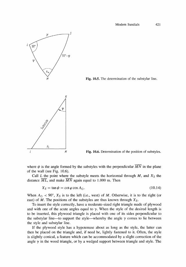
Modem Sundials 421
~_----.S
M Fig. 10.5. The detennination of the substylar line.
N
M Fig. 10.6. Detennination of the position of substyles.
where", is the angle formed by the substyles with the perpendicular MN in the plane of the wall (see Fig. 10.6).
Call L the point where the substyle meets the horizontal through M, and Xs the distance M L, and make M N again equal to 1.000 m. Then
Xs = tan'" = cOUpcoSA0' (10.14)
When A0 < 900 , Xs is to the left (i.e., west) of M. Otherwise, it is to the right (or east) of M. The positions of the substyles are thus known through Xs.
To insert the style correctly, have a moderate-sized right triangle made of plywood and with one of the acute angles equal to 'Y. When the style of the desired length is to be inserted, this plywood triangle is placed with one of its sides perpendicular to the substylar line-to support the style-whereby the angle 'Y comes to lie between the style and substylar line.
If the plywood style has a hypotenuse about as long as the style, the latter can then be placed on the triangle and, if need be, lightly fastened to it. Often, the style is slightly conical, a feature which can be accommodated by a slight correction of the angle 'Y in the wood triangle, or by a wedged support between triangle and style. The

422 F. Schmeidler
triangle is held in place by the weight of the style or else by a small nail, but the perpendicularity of the wooden triangle with the wall should be exactly maintained. The style can now be cemented, and will be in the proper position when the wood triangle is removed two days later.
10.5 Designs for Higher Accuracy
The methods mentioned so far permit the construction of sundials whose readings may depart from standard time by up to a quarter or half hour. Higher accuracy may be reached by making additional corrections as described in the subsections below.
10.5.1 Correction for Geographic Longitude
This correction, if desired, can be incorporated into the labeling of the scale. For instance, if the sundial is located at a longitude 5° or 20 minutes west of the meridian to which the standard time refers, then the addition of 20 minutes on all marks of the dial will correct for longitude, because standard time is by this average amount ahead of local solar time. The label 12h, located on the vertical dial directly below the style foot, is now displaced to the left, and below the foot will now be the mark 12h20m. A sundial corrected for longitude can be immediately recognized by its having 12h reading sidewise displaced from directly below the style.
10.5.2 Correction for the Equation of Time
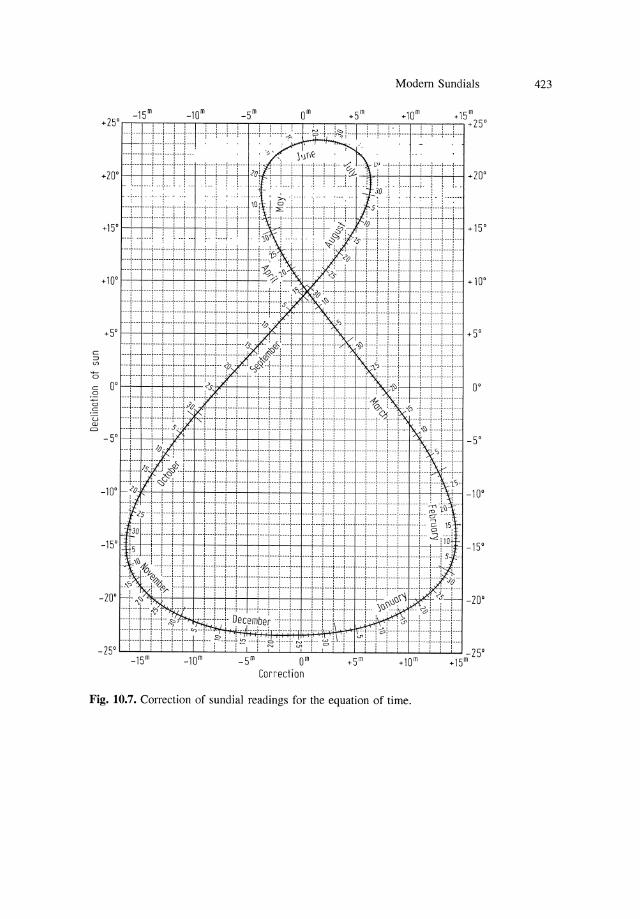
The changes of the equation of time from day to day, and from one year to the next, are below the reading precision of a sundial, which is at best 1 minute. To neglect the leap days creates a maximum error of one day, and the fastest change of the equation of time occurring in late December is only 112 minute per day. It is thus adequate to neglect February 29 and to use one permanent graph which reduces apparent to mean solar time for every day (Fig. 10.7). The date is read on the figure-of-eight, and the corresponding correction of the sundial reading on the top or bottom scale to obtain standard time.
Attempts have recently been made to incorporate this correction in sundials by suitable construction measures. Some successful attempts in this direction have been reported in Sky and Telescope [10.3]. In each case, the principle is to curve the gnomon or the dial or both in such a fashion that the readings include the correction for the equation of time.
Also worth reading is an article in the Journal of the British Astronomical Association (J.B.A.A) [1004], which discusses under what conditions the dial is equiangular in the sense that equal time intervals are represented by equal labeling intervals. Evidently, a sundial complying with this condition is more precise and convenient to read than would otherwise be the case. On the other hand, the construction of such a dial is necessarily more complex than that of an ordinary sundial. For a simplified theory of such dials, consult H. Lippold [10.7].
Modem Sundials 423
Fig. 10.7. Correction of sundial readings for the equation of time.

424 F. Schmeidler: Modem Sundials
References
10.1 Brunner, W.: Neuartige Sonnenuhr-Konstruktionen. Orion 33, 44 (1975). 10.2 Schumacher, H.: Sonnenuhren, Cal!wey, Mtinchen 1973. 10.3 Sky and Telescope 32, 256 (1966). 1 0.4 Journal of the British Astronomical Association 86, 7 (1976). 10.5 Peitz, A.: Sonnenuhren, Tabellen und Diagramme zur Berechnung, Cal!wey, Mtinchen
1978. 10.6 Hanke, W.: Ermittlung der Wandrichtung flir eine deklinierended Vertikal- (Stid-) Son
nenuhr durch Sonnenzeitazimutbeobachtung. Astronomie und Raumfahrt 3 (1975). 10.7 Lippold, H.: Zur Theorie der homogenen Sonnenuhr. Die Sterne 61, 228 (1985).