Modem Design, Implementation, and Testing Using NI’s LabVIEW Prof. Brian L. Evans Embedded Signal...
27
Modem Design, Implementation, and Testing Using NI’s LabVIEW Prof. Brian L. Evans Embedded Signal Processing Laboratory The University of Texas at Austin [email protected] Contributions by Vishal Monga, Zukang Shen, Ahmet Toker, and Ian Wong, UT Austin http://www.wncg.org http:// www.ece.utexas.edu
-
Upload
annalise-bodman -
Category
Documents
-
view
227 -
download
3
Transcript of Modem Design, Implementation, and Testing Using NI’s LabVIEW Prof. Brian L. Evans Embedded Signal...
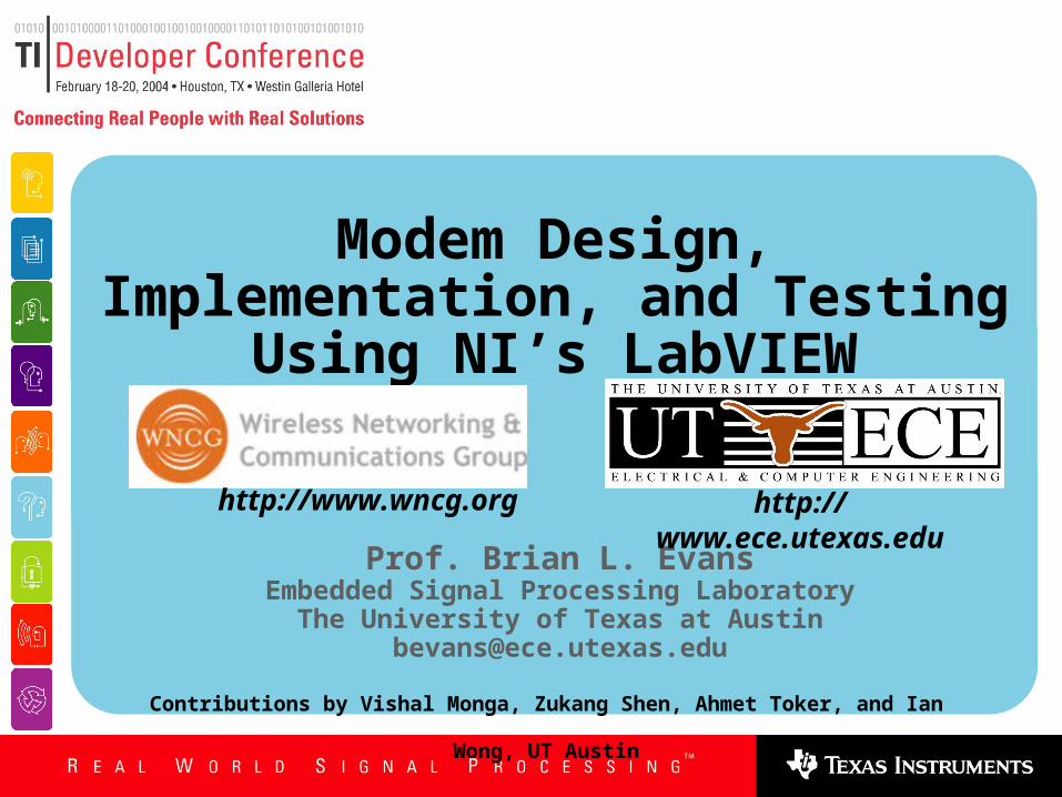
Modem Design, Implementation, and Testing Using NI’s LabVIEW
Prof. Brian L. EvansEmbedded Signal Processing Laboratory
The University of Texas at [email protected]
Contributions by Vishal Monga, Zukang Shen, Ahmet Toker, and Ian Wong, UT Austin
http://www.wncg.org http://www.ece.utexas.edu
2
Outline
Real-Time DSP Course
Single Carrier Transceiver
Sinusoidal Generation
Digital Filters
Data Scramblers
Pulse Amplitude Modulation
Quadrature Amplitude Modulation
Multicarrier Transceiver
Conclusion
3
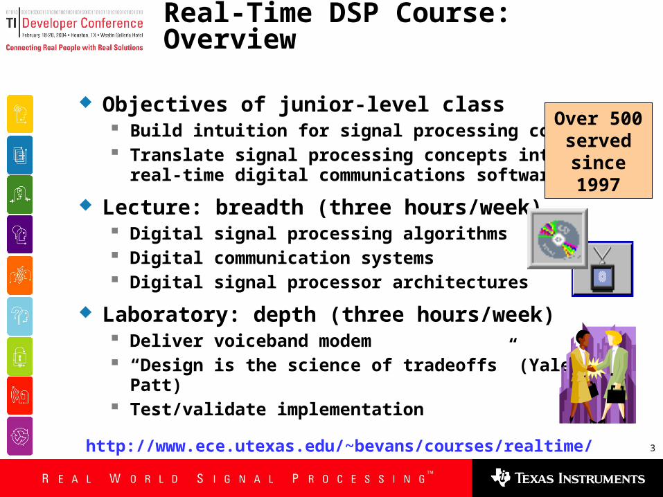
Real-Time DSP Course: Overview
Objectives of junior-level class Build intuition for signal processing concepts Translate signal processing concepts into
real-time digital communications software
Lecture: breadth (three hours/week) Digital signal processing algorithms Digital communication systems Digital signal processor architectures
Laboratory: depth (three hours/week) Deliver voiceband modem “Design is the science of tradeoffs” (Yale Patt) Test/validate implementation
Over 500 served
since 1997
http://www.ece.utexas.edu/~bevans/courses/realtime/
4
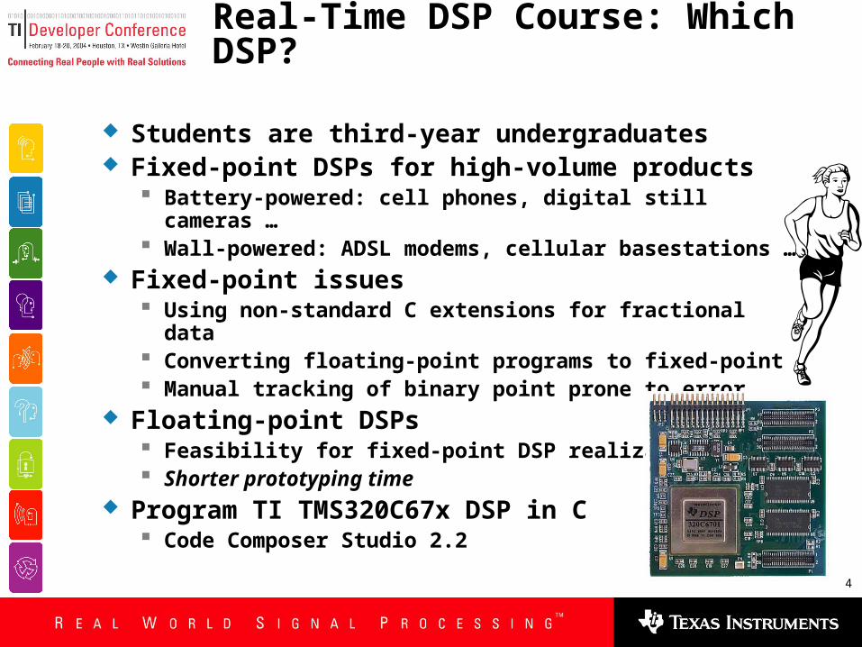
Real-Time DSP Course: Which DSP?
Students are third-year undergraduates Fixed-point DSPs for high-volume products
Battery-powered: cell phones, digital still cameras … Wall-powered: ADSL modems, cellular basestations …
Fixed-point issues Using non-standard C extensions for fractional data Converting floating-point programs to fixed-point Manual tracking of binary point prone to error
Floating-point DSPs Feasibility for fixed-point DSP realization Shorter prototyping time
Program TI TMS320C67x DSP in C Code Composer Studio 2.2
5
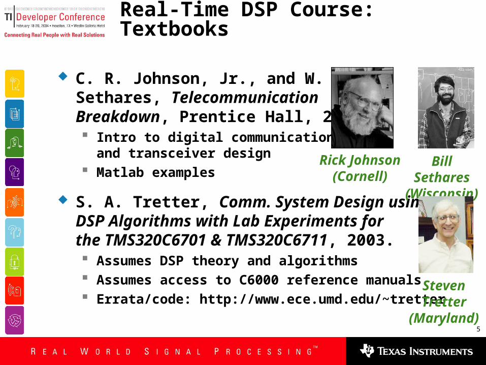
Real-Time DSP Course: Textbooks
C. R. Johnson, Jr., and W. A.Sethares, TelecommunicationBreakdown, Prentice Hall, 2004. Intro to digital communications
and transceiver design Matlab examples
S. A. Tretter, Comm. System Design usingDSP Algorithms with Lab Experiments forthe TMS320C6701 & TMS320C6711, 2003. Assumes DSP theory and algorithms Assumes access to C6000 reference manuals Errata/code: http://www.ece.umd.edu/~tretter
Bill Sethares (Wisconsin)
Rick Johnson (Cornell)
Steven Tretter (Maryland)
6
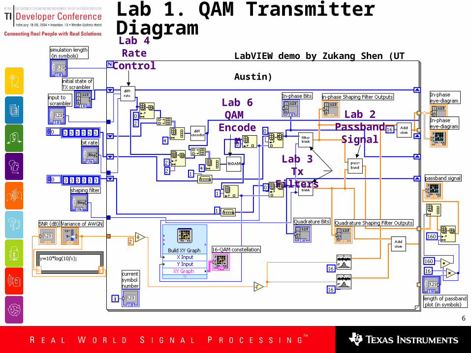
Lab 1. QAM Transmitter DiagramLab 4Rate
Control
Lab 6 QAM
Encoder
Lab 3Tx Filters
Lab 2 Passband
Signal
LabVIEW demo by Zukang Shen (UT Austin)

7
Lab 1. QAM Transmitter Diagram
LabVIEW Control
PanelQAM
PassbandSignal
Eye Diagram
LabVIEW demo by Zukang Shen (UT Austin)

8
square root raise cosine, roll-off = 0.75, SNR =
raise cosine, roll-off = 1, SNR = 30 dB
passband signal for 1200 bps mode
passband signal for 2400 bps mode
Lab 1. QAM Transmitter Diagram
9
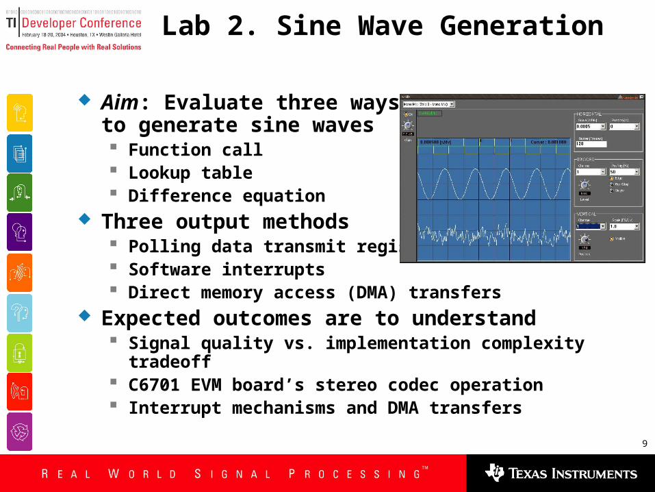
Lab 2. Sine Wave Generation
Aim: Evaluate three waysto generate sine waves Function call Lookup table Difference equation
Three output methods Polling data transmit register Software interrupts Direct memory access (DMA) transfers
Expected outcomes are to understand Signal quality vs. implementation complexity tradeoff C6701 EVM board’s stereo codec operation Interrupt mechanisms and DMA transfers
10
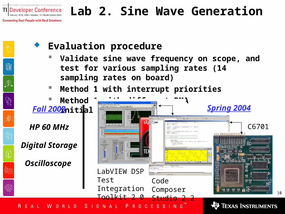
Lab 2. Sine Wave Generation
Evaluation procedure Validate sine wave frequency on scope, and test for
various sampling rates (14 sampling rates on board) Method 1 with interrupt priorities Method 1 with different DMA initialization(s)
LabVIEW DSP Test Integration Toolkit 2.0
Code Composer Studio 2.2
C6701
Fall 2003
HP 60 MHz
Digital Storage
Oscilloscope
Spring 2004
11
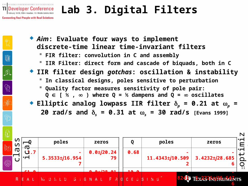
Lab 3. Digital Filters
Aim: Evaluate four ways to implementdiscrete-time linear time-invariant filters FIR filter: convolution in C and assembly IIR Filter: direct form and cascade of biquads, both in C
IIR filter design gotchas: oscillation & instability In classical designs, poles sensitive to perturbation Quality factor measures sensitivity of pole pair:
Q [ ½ , ) where Q = ½ dampens and Q = oscillates
Elliptic analog lowpass IIR filter p = 0.21 at p = 20 rad/s and s = 0.31 at s = 30 rad/s [Evans 1999]
Q poles zeros
1.7 -5.3533±j16.9547 0.0±j20.2479
61.0 -0.1636±j19.9899 0.0±j28.0184clas
sica
l
Q poles zeros
0.68 -11.4343±j10.5092 -3.4232±j28.6856
10.00 -1.0926±j21.8241 -1.2725±j35.5476 opti
miz
ed
12
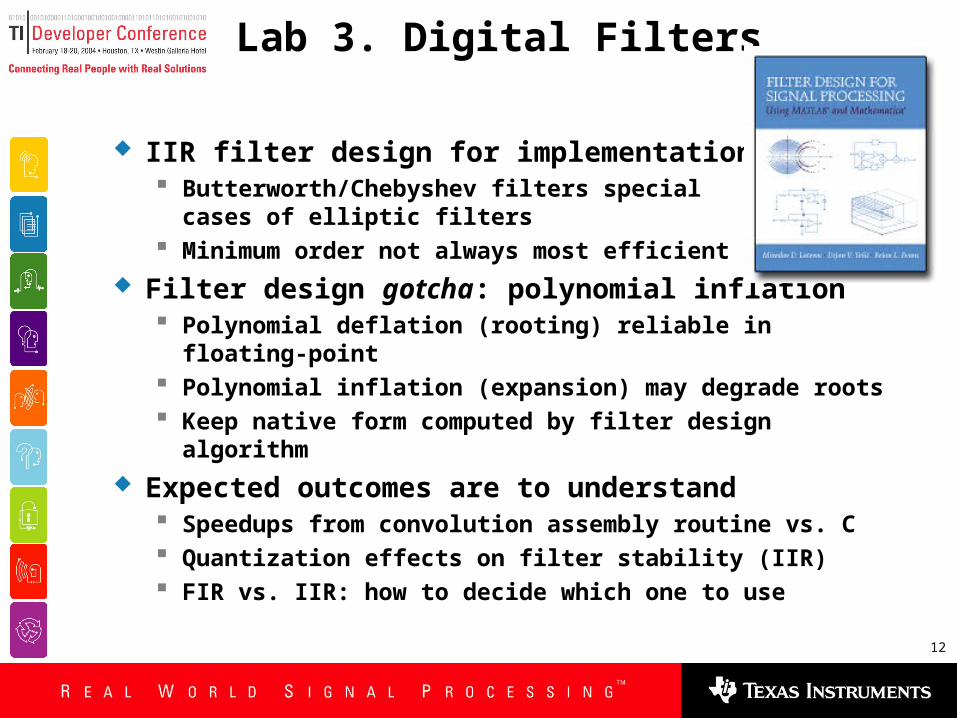
Lab 3. Digital Filters
IIR filter design for implementation Butterworth/Chebyshev filters special
cases of elliptic filters Minimum order not always most efficient
Filter design gotcha: polynomial inflation Polynomial deflation (rooting) reliable in floating-point Polynomial inflation (expansion) may degrade roots Keep native form computed by filter design algorithm
Expected outcomes are to understand Speedups from convolution assembly routine vs. C Quantization effects on filter stability (IIR) FIR vs. IIR: how to decide which one to use
13
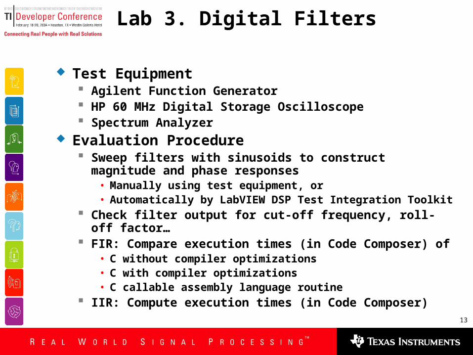
Lab 3. Digital Filters
Test Equipment Agilent Function Generator HP 60 MHz Digital Storage Oscilloscope Spectrum Analyzer
Evaluation Procedure Sweep filters with sinusoids to construct magnitude and
phase responses• Manually using test equipment, or• Automatically by LabVIEW DSP Test Integration Toolkit
Check filter output for cut-off frequency, roll-off factor… FIR: Compare execution times (in Code Composer) of
• C without compiler optimizations• C with compiler optimizations• C callable assembly language routine
IIR: Compute execution times (in Code Composer)

14
Lab 4. Data Scramblers
Aim: Generate pseudo-random bit sequences Build data scrambler for given connection polynomial Descramble data via descrambler Obtain statistics of scrambled binary sequence
Expected outcomes are to understand Principles of pseudo-noise (PN) sequence generation Identify applications in communication systems

15
Lab 4. Data Scramblers
Evaluation procedure Check scrambler output for various deterministic
sequences as input(s) Descrambler must recover input sequence from
scrambled one Test for sequence period, autocorrelation and other
significant statistical properties
Using DSP Test & Measurement Toolkit instead Compute autocorrelation of PN sequence Compare this autocorrelation with that of white noise
generated by LabVIEW to measue PN sequence quality
16
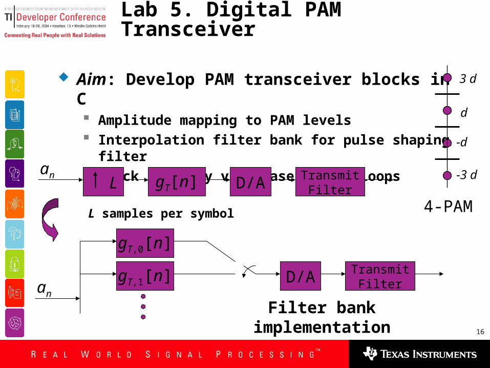
Lab 5. Digital PAM Transceiver
Aim: Develop PAM transceiver blocks in C Amplitude mapping to PAM levels Interpolation filter bank for pulse shaping filter Clock recovery via phase locked loops
gT,0[n]
gT,1[n]an
D/A TransmitFilter
Filter bank implementation
4-PAM
d
-d
-3 d
3 d
D/A TransmitFilter
an gT[n] L
L samples per symbol

17
Lab 5. Digital PAM Transceiver
Expected Outcomes are to understand Basics of PAM modulation Zero inter-symbol interference condition Clock synchronization issues
Test Equipment: Same as Lab 3 Evaluation Procedure
Generate eye diagram to visualize PAM signal quality Observe spectrum of modulated signal Prepare DSP modules to test symbol clock frequency
recovery subsystem
18
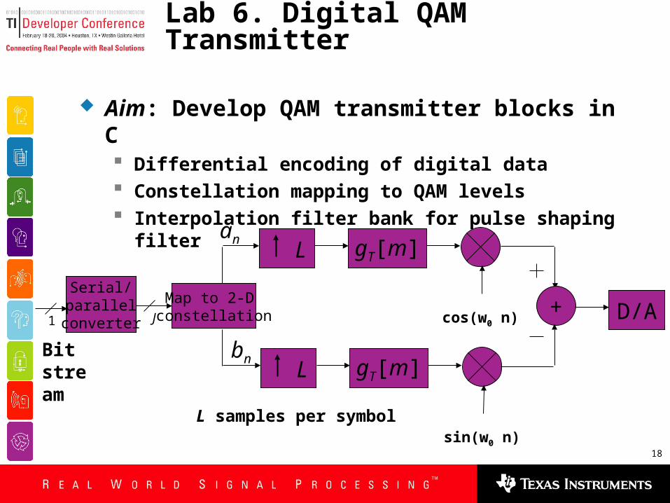
Lab 6. Digital QAM Transmitter
Aim: Develop QAM transmitter blocks in C Differential encoding of digital data Constellation mapping to QAM levels Interpolation filter bank for pulse shaping filter
D/A
an gT[m] L
+cos(w0 n)
bn gT[m] L
sin(w0 n)
Serial/parallel
converter1
Bit stream
Map to 2-D constellationJ
L samples per symbol
19
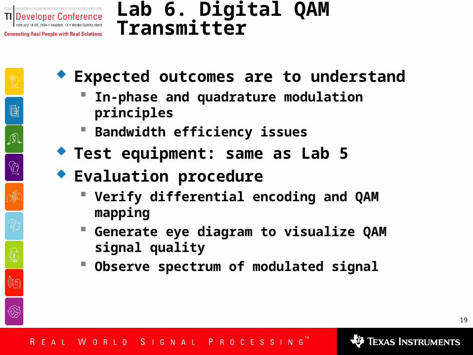
Lab 6. Digital QAM Transmitter
Expected outcomes are to understand In-phase and quadrature modulation principles Bandwidth efficiency issues
Test equipment: same as Lab 5 Evaluation procedure
Verify differential encoding and QAM mapping Generate eye diagram to visualize QAM signal quality Observe spectrum of modulated signal

20
Lab 7. Digital QAM Receiver – Part 1
Aim: Develop QAM receiver blocks in C Carrier recovery Coherent demodulation Decoding of QAM levels to digital data
Expected outcomes are to understand Carrier detection and phase adjustment Design of receive filter Probability of error analysis to evaluate decoder
Test equipment: Same as Lab 6 Evaluation procedure
Recover and display carrier on scope Regenerate eye diagram and QAM constellation Observe signal spectra at each decoding stage
21
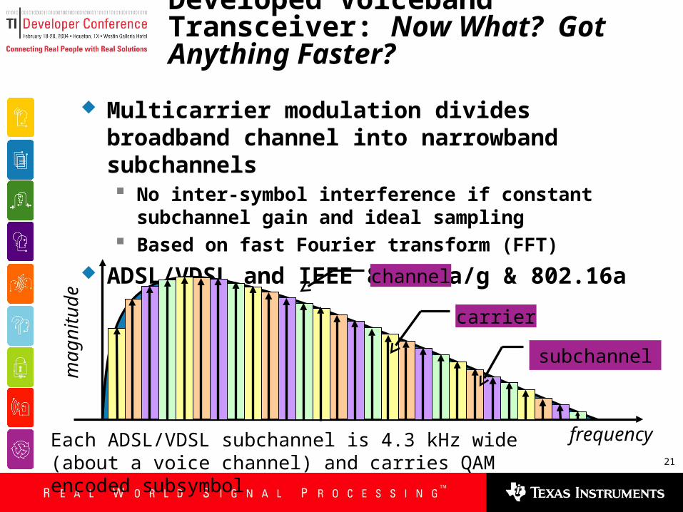
Multicarrier modulation divides broadband channel into narrowband subchannels No inter-symbol interference if constant subchannel
gain and ideal sampling Based on fast Fourier transform (FFT)
ADSL/VDSL and IEEE 802.11a/g & 802.16a
subchannel
frequency
magnitude
carrier
channel
Each ADSL/VDSL subchannel is 4.3 kHz wide (about a voice channel) and carries QAM encoded subsymbol
Developed Voiceband Transceiver: Now What? Got Anything Faster?
22
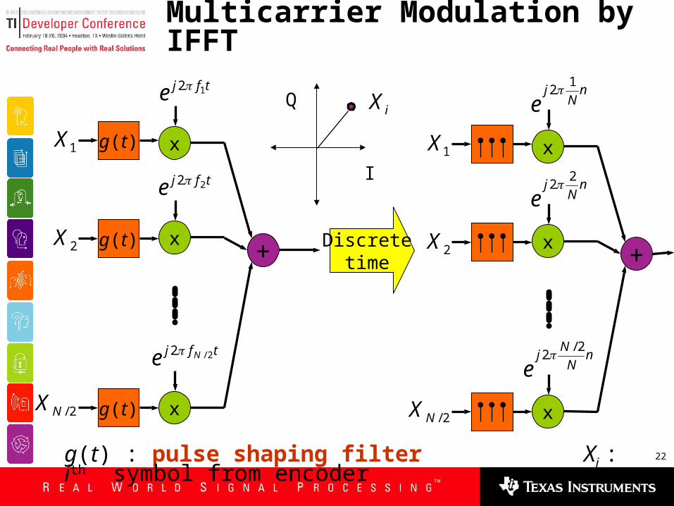
Multicarrier Modulation by IFFT
2/NX
x
tfje 12
1X
x
tfje 22
x
tfj Ne 2/2
+
g(t)
2X g(t)
g(t)
x
nN
je
12
1X
x
nN
je
22
x
nN
Nj
e2/
2
+2X
2/NX
Discretetime
g(t) : pulse shaping filter Xi : ith symbol from encoder
I
QiX
23
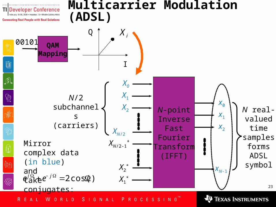
Multicarrier Modulation (ADSL)
N-pointInverse
FastFourier
Transform(IFFT)
X1
X2
X1*
x0
x1
x2
xN-1X2
*
XN/2
XN/2-1*
X0
N real-valuedtime
samplesformsADSL
symbol
N/2 subchannels
(carriers)
QAM Mapping
00101
I
QiX
Mirror complex data (in blue) andtake conjugates:
)cos( 2 jj ee
24
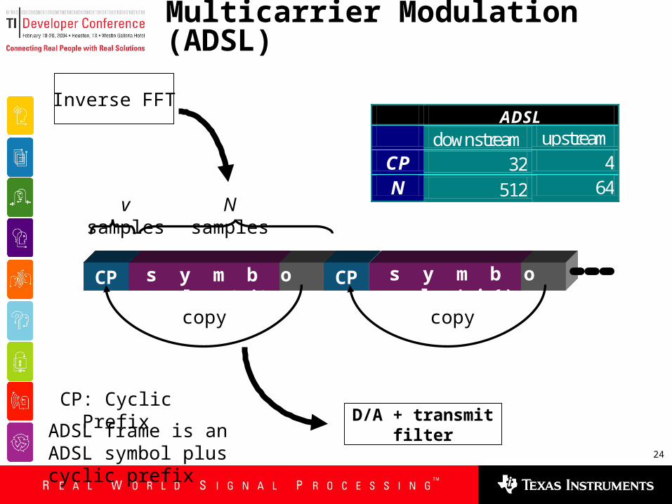
Multicarrier Modulation (ADSL)
CP: Cyclic Prefix
N samplesv samples
CP CPs y m b o l ( i ) s y m b o l ( i+1)
copy copy
D/A + transmit filter
ADSL downstream upstream
CP 32 4 N 512 64
Inverse FFT
ADSL frame is an ADSL symbol plus cyclic prefix
25
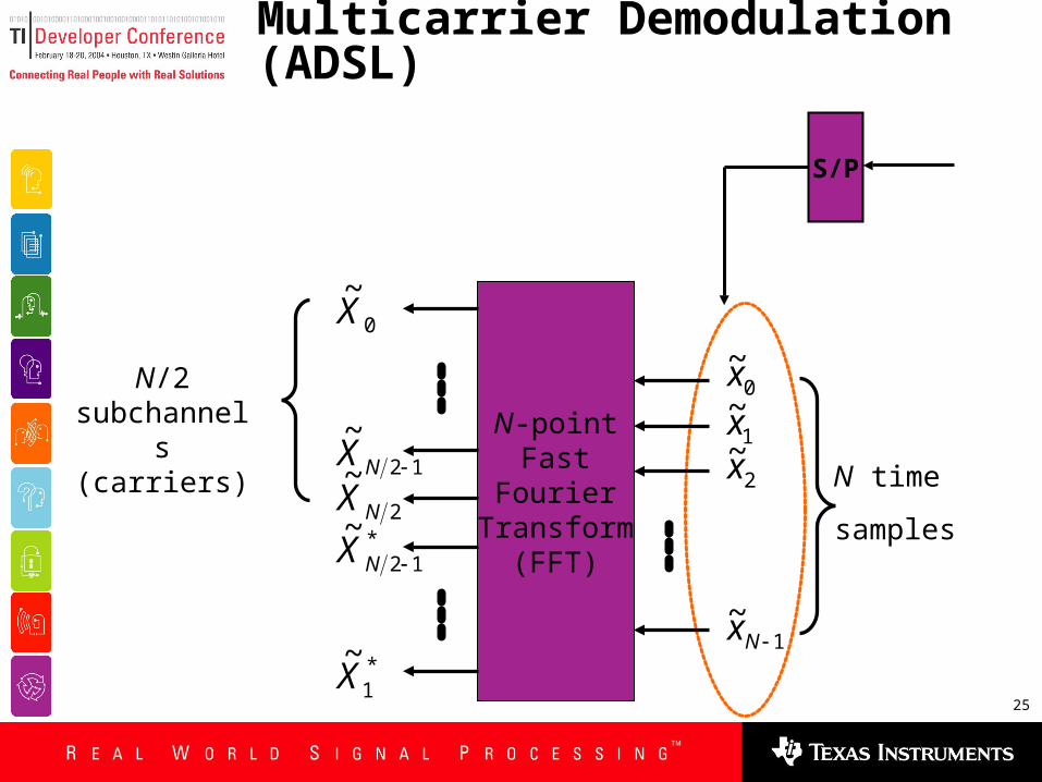
Multicarrier Demodulation (ADSL)
N-pointFast
FourierTransform
(FFT)
N time
samples
N/2 subchannels
(carriers)
S/P
*1
~X
*12
~NX
2
~NX
12
~NX
0
~X
0~x
1~x
2~x
1~
Nx

26
P/S QAM decoder
invert channel
=frequency
domainequalizer
S/P
quadrature amplitude
modulation (QAM) encoder
mirrordataand
N-IFFT
add cyclic prefix
P/SD/A +
transmit filter
N-FFTand
removemirrored
data
S/Premove
cyclic prefix
TRANSMITTER
RECEIVER
N/2 subchannels N real samples
N real samplesN/2 subchannels
time domain
equalizer (FIR filter)
receive filter
+A/D
channel
Bits
00110
each block programmed in lab and covered in one full lectureeach block covered in one full lecture
P/S parallel-to-serial S/P serial-to-parallel FFT fast Fourier transform
ADSL Transceiver: Data Xmission
2.208 MHz
27
Modem Design, Implementation, and Testing Using NI’s LabVIEW
Dr. Brian L. EvansAssociate Professor
The University of Texas at [email protected]
Telecom and University Tracks