
Models TSE-450, TSE-600, TSE-800-1, and TSE-1000 · FORM NO. L-20077-X-1018 6 NOTE Nexen...
14
FORM NO. L-20077-X-1018 Models TSE-450, TSE-600, TSE-800-1, and TSE-1000
Transcript of Models TSE-450, TSE-600, TSE-800-1, and TSE-1000 · FORM NO. L-20077-X-1018 6 NOTE Nexen...
1 FORM NO. L-20077-X-1018
Models TSE-450, TSE-600, TSE-800-1, and TSE-1000
2FORM NO. L-20077-X-1018
Copyright 2018 Nexen Group, Inc.
Nexen Group, Inc.560 Oak Grove Parkway
Vadnais Heights, Minnesota 55127
ISO 9001 Certified
This document is the original, non-translated, version.
Conformity Declaration: In accordance with Appendix II B of CE Machinery Directive (2006/42/EC):
A Declaration of Incorporation of Partly Completed Machinery evaluation for the applicable EU directives was carried out for this product in accordance with the Machinery Directive. The declaration of incorporation is set out in writing in a separate document and can be requested if required.
This machinery is incomplete and must not be put into service until the machinery into which it is to be incorporated has been declared in conformity with the applicable provisions of the Directive.
Read this manual carefully before installation and operation. Follow Nexen’s instructions and integrate this unit into your system with care. This unit should be installed, operated and maintained by qualified personnel ONLY. Improper installation can damage your system, cause injury or death. Comply with all applicable codes.
DANGER
In accordance with Nexen’s established policy of constant product improvement, the specifications contained in this manual are subject to change without notice. Technical data listed in this manual are based on the latest information available at the time of printing and are also subject to change without notice.
Technical Support: 800-843-7445 (651) 484-5900
www.nexengroup.com
3 FORM NO. L-20077-X-1018
Table of Contents
General Specifications ----------------------------------------------------------------------------------------------------------------------- 4
General Safety Precautions ----------------------------------------------------------------------------------------------------------------- 4
Installation ----------------------------------------------------------------------------------------------------------------------------------------- 5
Brake Guard Installation ---------------------------------------------------------------------------------------------------------------------- 6
Lubrication ----------------------------------------------------------------------------------------------------------------------------------------- 6
Air Connections --------------------------------------------------------------------------------------------------------------------------------- 7
Operation ------------------------------------------------------------------------------------------------------------------------------------------ 8
Maintenance ---------------------------------------------------------------------------------------------------------------------------------------8
Troubleshooting ----------------------------------------------------------------------------------------------------------------------------------9
Parts Replacement:
Friction Facings -------------------------------------------------------------------------------------------------------------------------- 10
Bearing, Compression Springs, and O-Ring Seals ------------------------------------------------------------------------- 10
Replacement Parts List --------------------------------------------------------------------------------------------------------------------- 12
Accessories ------------------------------------------------------------------------------------------------------------------------------------- 13
Facing and Repair Kits ---------------------------------------------------------------------------------------------------------------------- 13
Warranty ------------------------------------------------------------------------------------------------------------------------------------------ 14
4FORM NO. L-20077-X-1018
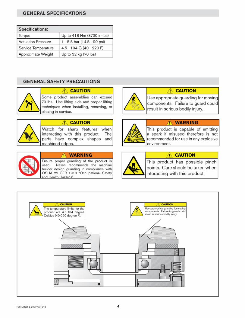
GENERAL SPECIFICATIONS
GENERAL SAFETY PRECAUTIONS
CAUTION
Use appropriate guarding for moving components. Failure to guard could result in serious bodily injury.
CAUTION
The temperature limits for the product are 4.5-104 degree Celsius (40-220 degree F).
Specifications:Torque Up to 418 Nm (3700 in-lbs)
Actuation Pressure 1 - 5.5 bar (14.5 - 90 psi)
Service Temperature 4.5 - 104 C (40 - 220 F)
Approximate Weight Up to 32 kg (70 lbs)
CAUTIONSome product assemblies can exceed 70 lbs. Use lifting aids and proper lifting techniques when installing, removing, or placing in service.
CAUTIONWatch for sharp features when interacting with this product. The parts have complex shapes and machined edges.
CAUTION
Use appropriate guarding for moving components. Failure to guard could result in serious bodily injury.
WARNINGThis product is capable of emitting a spark if misused therefore is not recommended for use in any explosive environment.
WARNINGEnsure proper guarding of the product is used. Nexen recommends the machine builder design guarding in compliance with OSHA 29 CFR 1910 “Occupational Safety and Health Hazards”.
CAUTION
This product has possible pinch points. Care should be taken when interacting with this product.
5 FORM NO. L-20077-X-1018
INSTALLATION
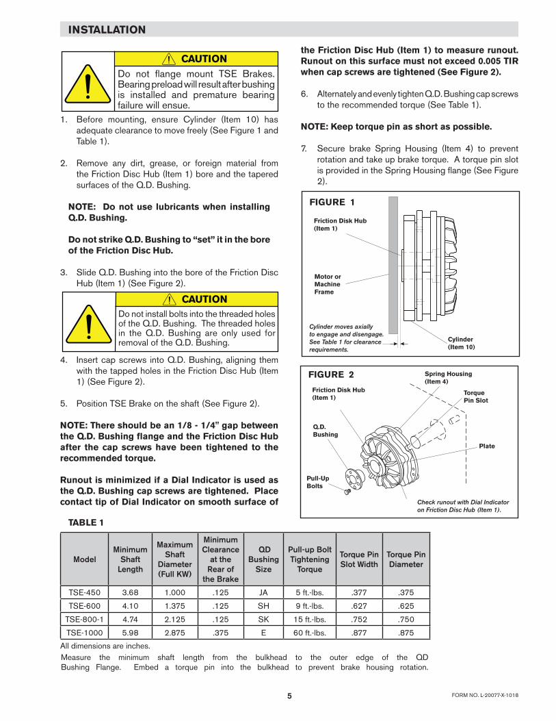
1. Before mounting, ensure Cylinder (Item 10) has adequate clearance to move freely (See Figure 1 and Table 1).
2. Remove any dirt, grease, or foreign material from the Friction Disc Hub (Item 1) bore and the tapered surfaces of the Q.D. Bushing.
NOTE: Do not use lubricants when installing Q.D. Bushing.
Do not strike Q.D. Bushing to “set” it in the bore of the Friction Disc Hub.
3. Slide Q.D. Bushing into the bore of the Friction Disc Hub (Item 1) (See Figure 2).
4. Insert cap screws into Q.D. Bushing, aligning them with the tapped holes in the Friction Disc Hub (Item 1) (See Figure 2).
5. Position TSE Brake on the shaft (See Figure 2).
NOTE: There should be an 1/8 - 1/4" gap between the Q.D. Bushing flange and the Friction Disc Hub after the cap screws have been tightened to the recommended torque.
Runout is minimized if a Dial Indicator is used as the Q.D. Bushing cap screws are tightened. Place contact tip of Dial Indicator on smooth surface of
Cylinder moves axiallyto engage and disengage.See Table 1 for clearancerequirements.
FIGURE 1
Friction Disk Hub(Item 1)
Motor orMachineFrame
Cylinder(Item 10)
FIGURE 2
Friction Disk Hub(Item 1)
Q.D.Bushing
Pull-UpBolts
Spring Housing(Item 4)
TorquePin Slot
Plate
Check runout with Dial Indicatoron Friction Disc Hub (Item 1).
CAUTIONDo not flange mount TSE Brakes. Bearing preload will result after bushing is installed and premature bearing failure will ensue.
CAUTIONDo not install bolts into the threaded holes of the Q.D. Bushing. The threaded holes in the Q.D. Bushing are only used for removal of the Q.D. Bushing.
TABLE 1
ModelMinimum
Shaft Length
Maximum Shaft
Diameter(Full KW)
Minimum Clearance
at the Rear of
the Brake
QD Bushing
Size
Pull-up Bolt Tightening
Torque
Torque Pin Slot Width
Torque Pin Diameter
TSE-450 3.68 1.000 .125 JA 5 ft.-lbs. .377 .375
TSE-600 4.10 1.375 .125 SH 9 ft.-lbs. .627 .625
TSE-800-1 4.74 2.125 .125 SK 15 ft.-lbs. .752 .750
TSE-1000 5.98 2.875 .375 E 60 ft.-lbs. .877 .875
All dimensions are inches. Measure the minimum shaft length from the bulkhead to the outer edge of the QD Bushing Flange. Embed a torque pin into the bulkhead to prevent brake housing rotation.
the Friction Disc Hub (Item 1) to measure runout. Runout on this surface must not exceed 0.005 TIR when cap screws are tightened (See Figure 2).
6. Alternately and evenly tighten Q.D. Bushing cap screws to the recommended torque (See Table 1).
NOTE: Keep torque pin as short as possible.
7. Secure brake Spring Housing (Item 4) to prevent rotation and take up brake torque. A torque pin slot is provided in the Spring Housing flange (See Figure 2).
6FORM NO. L-20077-X-1018
NOTENexen pneumatically actuated devices require clean, pressure regulated air for maximum performance and life. All seals in Nexen pneumatically operated devices are lubricated for life, and do not require additional lubrication.
However, some customers prefer to use an air line lubricator, which injects oil into the pressurized air, forcing an oil mist into the air chamber. This is acceptable, but care must be taken to ensure once an air mist lubrication system is used, it is continually used over the life of the product as the oil mist may wash free the factory installed lubrication.
Locate the lubricator above and within ten feet of the product, and use low viscosity oil such as SAE-10.
Synthetic lubricants are not recommended.
Nexen product's bearings are shielded and pre-lubricated, and require no further lubrication.
LUBRICATOR DRIP RATE SETTINGS
1. Close and disconnect the air line from the unit.
2. Turn the Lubricator Adjustment Knob counterclockwise three complete turns.
3. Open the air line.
LUBRICATION
CAUTION
These settings are for Nexen supplied lubricators. If you are not using a Nexen lubricator, calibration must follow the manufacturer's suggested procedure.
4. Close the air line to the unit when a drop of oil forms in the Lubricator Sight Gage.
5. Connect the air line to the unit.
6. Turn the Lubricator Adjustment Knob clockwise until closed.
7. Turn the Lubricator Adjustment Knob counterclockwise one-third turn.
8. Open the air line to the unit.
BRAKE GUARD INSTALLATION
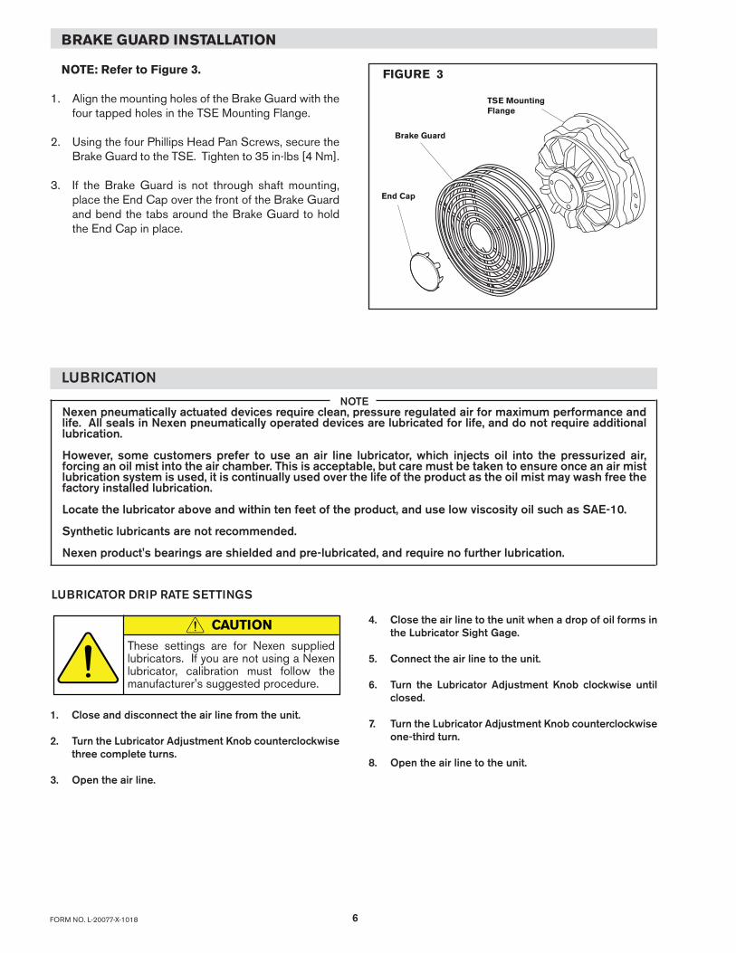
NOTE: Refer to Figure 3.
1. Align the mounting holes of the Brake Guard with the four tapped holes in the TSE Mounting Flange.
2. Using the four Phillips Head Pan Screws, secure the Brake Guard to the TSE. Tighten to 35 in-lbs [4 Nm].
3. If the Brake Guard is not through shaft mounting, place the End Cap over the front of the Brake Guard and bend the tabs around the Brake Guard to hold the End Cap in place.
FIGURE 3
Brake Guard
End Cap
TSE Mounting Flange
7 FORM NO. L-20077-X-1018
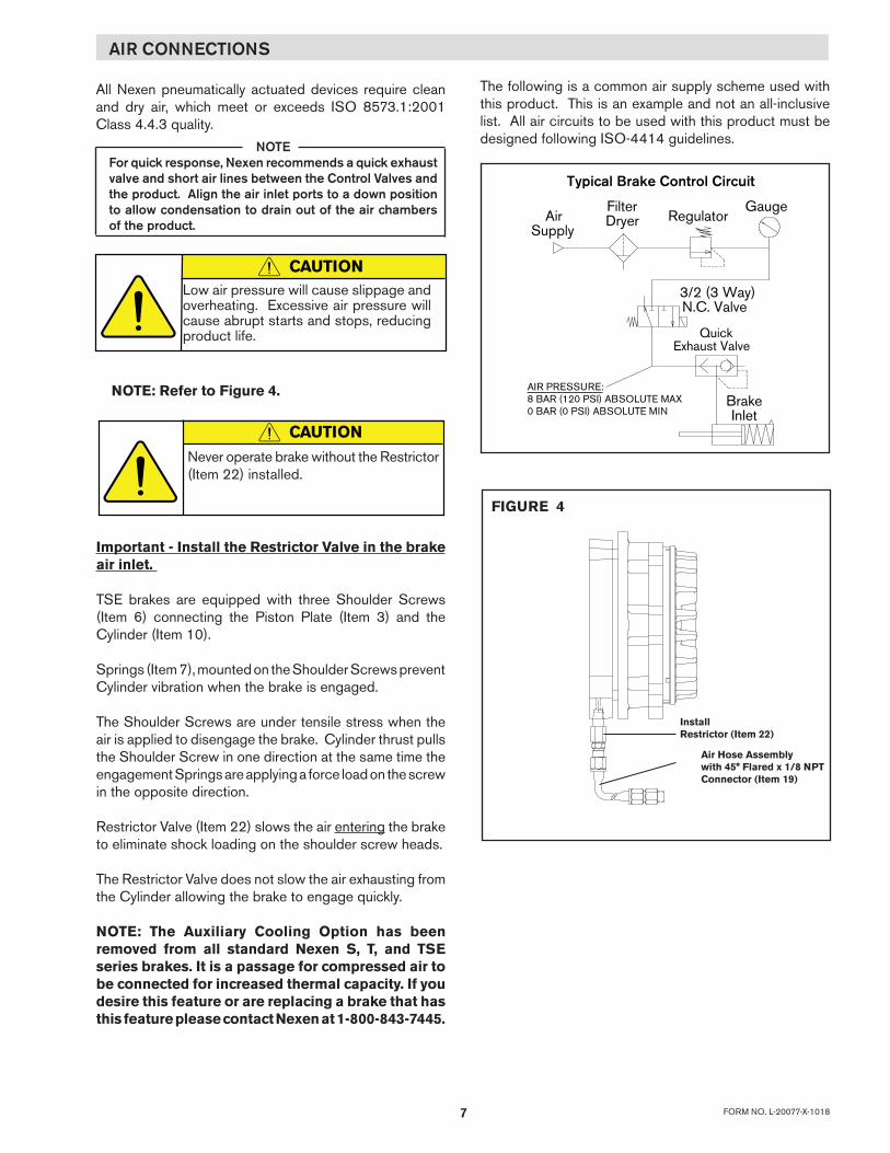
AirSupply
Brake Inlet
GaugeRegulator
FilterDryer
Typical Brake Control Circuit
3/2 (3 Way)N.C. Valve
Quick Exhaust Valve
AIR PRESSURE: 8 BAR (120 PSI) ABSOLUTE MAX 0 BAR (0 PSI) ABSOLUTE MIN
AIR CONNECTIONS
NOTEFor quick response, Nexen recommends a quick exhaust valve and short air lines between the Control Valves and the product. Align the air inlet ports to a down position to allow condensation to drain out of the air chambers of the product.
CAUTIONLow air pressure will cause slippage and overheating. Excessive air pressure will cause abrupt starts and stops, reducing product life.
All Nexen pneumatically actuated devices require clean and dry air, which meet or exceeds ISO 8573.1:2001 Class 4.4.3 quality.
The following is a common air supply scheme used with this product. This is an example and not an all-inclusive list. All air circuits to be used with this product must be designed following ISO-4414 guidelines.
NOTE: Refer to Figure 4.
FIGURE 4
Important - Install the Restrictor Valve in the brake air inlet.
TSE brakes are equipped with three Shoulder Screws (Item 6) connecting the Piston Plate (Item 3) and the Cylinder (Item 10).
Springs (Item 7), mounted on the Shoulder Screws prevent Cylinder vibration when the brake is engaged.
The Shoulder Screws are under tensile stress when the air is applied to disengage the brake. Cylinder thrust pulls the Shoulder Screw in one direction at the same time the engagement Springs are applying a force load on the screw in the opposite direction.
Restrictor Valve (Item 22) slows the air entering the brake to eliminate shock loading on the shoulder screw heads.
The Restrictor Valve does not slow the air exhausting from the Cylinder allowing the brake to engage quickly.
NOTE: The Auxiliary Cooling Option has been removed from all standard Nexen S, T, and TSE series brakes. It is a passage for compressed air to be connected for increased thermal capacity. If you desire this feature or are replacing a brake that has this feature please contact Nexen at 1-800-843-7445.
InstallRestrictor (Item 22)
Air Hose Assemblywith 45° Flared x 1/8 NPT Connector (Item 19)
CAUTION
Never operate brake without the Restrictor (Item 22) installed.
8FORM NO. L-20077-X-1018
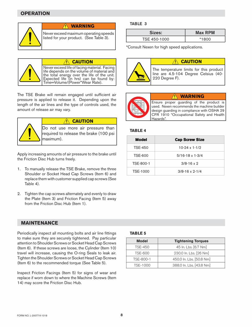
The TSE Brake will remain engaged until sufficient air pressure is applied to release it. Depending upon the length of the air lines and the type of controls used, the amount of release air may vary.
Apply increasing amounts of air pressure to the brake until the Friction Disc Hub turns freely.
1. To manually release the TSE Brake, remove the three Shoulder or Socket Head Cap Screws (Item 6) and replace them with customer supplied cap screws (See Table 4).
2. Tighten the cap screws alternately and evenly to draw the Plate (Item 3) and Friction Facing (Item 5) away from the Friction Disc Hub (Item 1).
MAINTENANCE
Periodically inspect all mounting bolts and air line fittings to make sure they are securely tightened. Pay particular attention to Shoulder Screws or Socket Head Cap Screws (Item 6). If these screws are loose, the Cylinder (Item 10) travel will increase, causing the O-ring Seals to leak air. Tighten the Shoulder Screws or Socket Head Cap Screws (Item 6) to the recommended torque (See Table 5).
Inspect Friction Facings (Item 5) for signs of wear and replace if worn down to where the Machine Screws (Item 14) may score the Friction Disc Hub.
TABLE 4
ledoM ledoM ledoM ledoM ledoM eziSwercSpaC eziSwercSpaC eziSwercSpaC eziSwercSpaC eziSwercSpaC
054-EST 2/1-1x42-01
006-EST 4/3-1x81-61/5
1-008-EST 2x61-8/3
0001-EST 4/1-2x61-8/3
TABLE 5
Model Tightening Torques
TSE-450 45 In. Lbs. [6.7 Nm]
TSE-600 230.0 In. Lbs. [26 Nm]
TSE-800-1 450.0 In. Lbs. [50.8 Nm]
TSE-1000 388.0 In. Lbs. [43.8 Nm]
OPERATION
CAUTIONDo not use more air pressure than required to release the brake (100 psi maximum).
WARNING
Never exceed maximum operating speeds listed for your product. (See Table 3).
CAUTIONCAUTION
TABLE 3
The temperature limits for this product line are 4.5-104 Degree Celsius (40-220 Degree F).
Never exceed life of facing material. Facing life depends on the volume of material and the total energy over the life of the unit. Expected life (in hrs) can be found by: Time=Volume/(Power*Wear Rate).
Sizes: Max RPMTSE 450-1000 *1800
*Consult Nexen for high speed applications.
WARNINGEnsure proper guarding of the product is used. Nexen recommends the machine builder design guarding in compliance with OSHA 29 CFR 1910 “Occupational Safety and Health Hazards”.
9 FORM NO. L-20077-X-1018
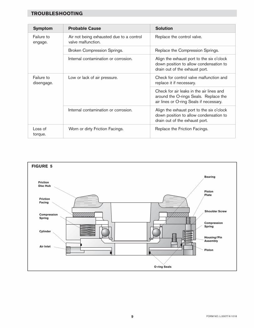
TROUBLESHOOTING
FIGURE 5
FrictionFacing
PistonPlate
CompressionSpring
O-ring Seals
Air InletPiston
Bearing
FrictionDisc Hub
Cylinder
Shoulder Screw
CompressionSpring
Housing/PinAssembly
motpmyS esuaCelbaborP noituloS
oteruliaF.egagne
lortnocaoteuddetsuahxegniebtonriA.noitcnuflamevlav
.evlavlortnocehtecalpeR
.sgnirpSnoisserpmoCnekorB .sgnirpSnoisserpmoCehtecalpeR
.noisorrocronoitanimatnoclanretnI kcolc'oxisehtottroptsuahxeehtngilAotnoitasnednocwollaotnoitisopnwod
.troptsuahxeehtfotuoniard
oteruliaF.egagnesid
.erusserpriafokcalrowoL dnanoitcnuflamevlavlortnocrofkcehC.yrassecenfitiecalper
dnasenilriaehtniskaelriarofkcehCehtecalpeR.slaeSsgnir-Oehtdnuora
.yrassecenfislaeSgnir-Orosenilria
.noisorrocronoitanimatnoclanretnI kcolc'oxisehtottroptsuahxeehtngilAotnoitasnednocwollaotnoitisopnwod
.troptsuahxeehtfotuoniard
fossoL.euqrot
.sgnicaFnoitcirFytridronroW .sgnicaFnoitcirFehtecalpeR
10FORM NO. L-20077-X-1018
PARTS REPLACEMENT
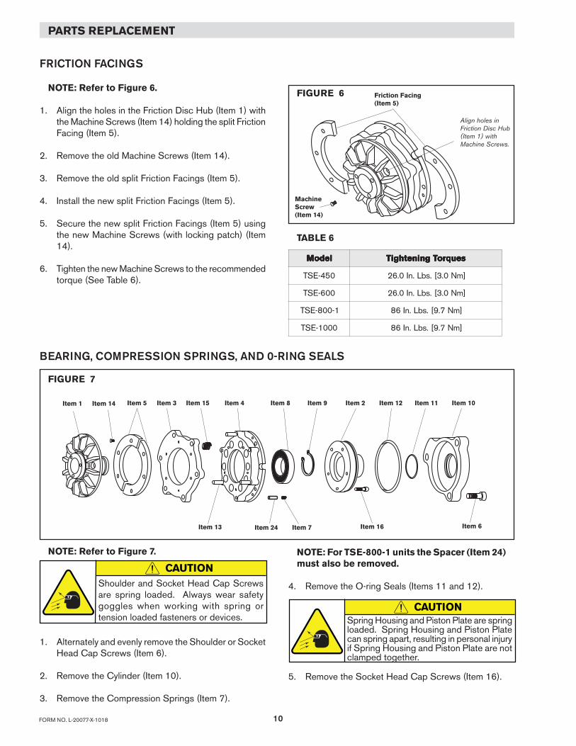
FRICTION FACINGS
NOTE: Refer to Figure 6.
1. Align the holes in the Friction Disc Hub (Item 1) with the Machine Screws (Item 14) holding the split Friction Facing (Item 5).
2. Remove the old Machine Screws (Item 14).
3. Remove the old split Friction Facings (Item 5).
4. Install the new split Friction Facings (Item 5).
5. Secure the new split Friction Facings (Item 5) using the new Machine Screws (with locking patch) (Item 14).
6. Tighten the new Machine Screws to the recommended torque (See Table 6).
FIGURE 6
Align holes in Friction Disc Hub (Item 1) withMachine Screws.
Friction Facing(Item 5)
MachineScrew(Item 14)
TABLE 6
Item 14Item 1 Item 5 Item 3 Item 4 Item 8 Item 9 Item 2 Item 12 Item 11 Item 10
Item 16Item 7
BEARING, COMPRESSION SPRINGS, AND 0-RING SEALS
FIGURE 7
Item 13
Item 15
Item 24 Item 6
NOTE: Refer to Figure 7.
1. Alternately and evenly remove the Shoulder or Socket Head Cap Screws (Item 6).
2. Remove the Cylinder (Item 10).
3. Remove the Compression Springs (Item 7).
NOTE: For TSE-800-1 units the Spacer (Item 24) must also be removed.
4. Remove the O-ring Seals (Items 11 and 12).
5. Remove the Socket Head Cap Screws (Item 16).
ledoM ledoM ledoM ledoM ledoM seuqroTgninethgiT seuqroTgninethgiT seuqroTgninethgiT seuqroTgninethgiT seuqroTgninethgiT
054-EST ]mN0.3[.sbL.nI0.62
006-EST ]mN0.3[.sbL.nI0.62
1-008-EST ]mN7.9[.sbL.nI68
0001-EST ]mN7.9[.sbL.nI68
CAUTIONShoulder and Socket Head Cap Screws are spring loaded. Always wear safety goggles when working with spring or tension loaded fasteners or devices.
CAUTIONSpring Housing and Piston Plate are spring loaded. Spring Housing and Piston Plate can spring apart, resulting in personal injury if Spring Housing and Piston Plate are not clamped together.
11 FORM NO. L-20077-X-1018
6. Remove the Piston (Item 2).
7. Using C-Clamps, compress the Spring Housing (Item 4) against Piston Plate (Item 3).
8. Remove the Retaining Ring (Item 9).
9. Press the Friction Disc Hub (Item 1) out of the Bearing (Item 8).
10. Slowly unclamp the Spring Housing (Item 4) and Piston Plate (Item 3).
11. Using a bearing puller, remove the Bearing (Item 8) from the Spring Housing (Item 4).
12. Clean the bearing bore of the Spring Housing (Item 4) with fresh safety solvent to remove all old Loctite® residue.
13. Apply an adequate amount of Loctite® 680 to evenly coat O.D. of new Bearing (Item 8) and press new Bearing into Spring Housing (Item 4).
14. Equally space the Compression Springs (Item 15) in the spring pockets of the Spring Housing (Item 4).
15. Slide the Piston Plate (Item 3) onto the Dowel Pins (Item 13) of the Spring Housing (Item 4).
16. Using C-clamps, compress the Piston Plate (Item 3) against the Compression Springs (Item 15) and Spring Housing (Item 4).
17. Press the Friction Disc Hub (Item 1) into the new Bearing (Item 8).
18. Reinstall the Retaining Ring (Item 9).
19. Remove the C-clamps securing the Spring Housing against the Piston Plate.
20. Press the Piston (Item 2) into the Spring Housing (Item 4).
21. Apply Loctite® 242 to entire length and under the heads of the Socket Head Cap Screw (Item 16). Alternately and evenly tighten the Socket Head Cap Screws to the recommended torque (See Table 7).
NOTE: Loctite® must seal all air gaps between the Socket Head Cap Screws (Item 16) and the clearance holes.
22. Reinstall the Compression Springs (Item 7).
NOTE: For TSE-800-1 units, also install Spacer (Item 24).
23. Clean the O-ring grooves of the Piston (Item 2) and Cylinder (Item 10); then, lubricate the new O-rings and O-ring contact surfaces with a thin film of fresh O-ring lubricant.
NOTE: Avoid pinching of O-ring Seals when assembling Piston and Cylinder.
24. Install the new O-ring Seals (Items 11 and 12).
25. Slide the Cylinder (Item 10) onto the Piston (Item 2).
26. TSE-450 and TSE-600: Apply Loctite® 242 to the threads of the Socket Head Cap Screws or Shoulder Screws (Item 6); then, alternately and evenly tighten them to the recommended torque (See Table 7).
TSE-800-1: Alternately and evenly tighten the Socket Head Cap Screws (Item 6) to the recommended torque (See Table 7). Do not use lubricants or thread locking compounds on the Socket Head Cap Screws (Item 6).
TSE-1000: Lubricate the tapped holes in the Piston Plate (Item 3) with a light machine oil before installing the Shoulder Screws (Item 6); then, alternately and evenly tighten them to the recommended torque (See Table 7).
TABLE 7
ledoM ledoM ledoM ledoM ledoM 6metI 6metI 6metI 6metI 6metI 61metI 61metI 61metI 61metI 61metI
054-EST.sbL.nI0.54
]mN0.5[.sbL.nI0.06
]mN7.6[
006-EST.sbL.nI0.032
]mN0.62[.sbL.nI0.06
]mN7.6[
1-008-EST.sbL.nI0.003
]mN70.43[.sbL.nI0.59
]mN7.01[
0001-EST.sbL.nI0.883
]mN8.34[.sbL.nI0.59
]mN7.01[
CAUTIONWorking with spring loaded or tension loaded fasteners and devices can cause injury. Wear safety glasses and take the appropriate safety precautions.
CAUTIONThe TSE-1000 uses Nexen Shoulder Screws only. The Shoulder Screws are specifically designed for high stress and prevailing torque capabilities.
12FORM NO. L-20077-X-1018
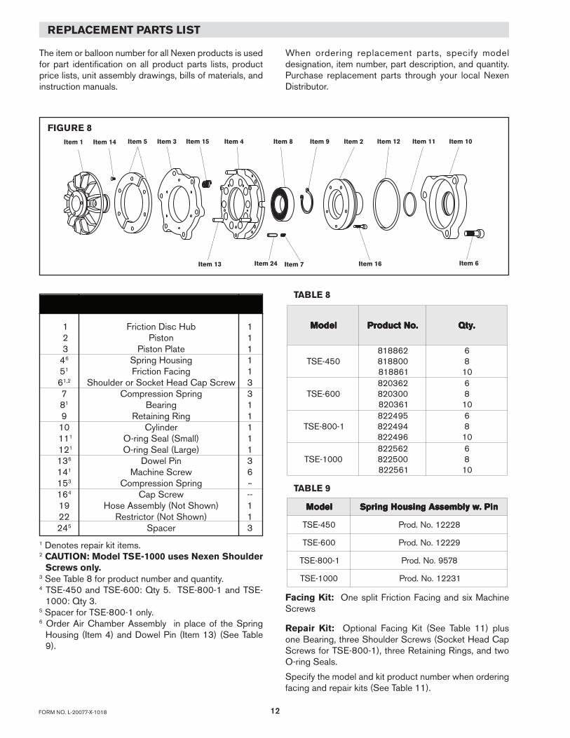
REPLACEMENT PARTS LIST
The item or balloon number for all Nexen products is used for part identification on all product parts lists, product price lists, unit assembly drawings, bills of materials, and instruction manuals.
FIGURE 8
When ordering replacement parts, specify model designation, item number, part description, and quantity. Purchase replacement parts through your local Nexen Distributor.
ITEM DESCRIPTION QTY
1 Friction Disc Hub 1 2 Piston 1 3 Piston Plate 1 46 Spring Housing 1 51 Friction Facing 1 61,2 Shoulder or Socket Head Cap Screw 3 7 Compression Spring 3 81 Bearing 1 9 Retaining Ring 1 10 Cylinder 1 111 O-ring Seal (Small) 1 121 O-ring Seal (Large) 1 136 Dowel Pin 3 141 Machine Screw 6 153 Compression Spring -- 164 Cap Screw -- 19 Hose Assembly (Not Shown) 1 22 Restrictor (Not Shown) 1 245 Spacer 3
Facing Kit: One split Friction Facing and six Machine Screws Repair Kit: Optional Facing Kit (See Table 11) plus one Bearing, three Shoulder Screws (Socket Head Cap Screws for TSE-800-1), three Retaining Rings, and two O-ring Seals.
Specify the model and kit product number when ordering facing and repair kits (See Table 11).
1 Denotes repair kit items.2 CAUTION: Model TSE-1000 uses Nexen Shoulder
Screws only.3 See Table 8 for product number and quantity.4 TSE-450 and TSE-600: Qty 5. TSE-800-1 and TSE-
1000: Qty 3.5 Spacer for TSE-800-1 only.6 Order Air Chamber Assembly in place of the Spring
Housing (Item 4) and Dowel Pin (Item 13) (See Table 9).
TABLE 8
TABLE 9
ledoM ledoM ledoM ledoM ledoM niP.wylbmessAgnisuoHgnirpS niP.wylbmessAgnisuoHgnirpS niP.wylbmessAgnisuoHgnirpS niP.wylbmessAgnisuoHgnirpS niP.wylbmessAgnisuoHgnirpS
054-EST 82221.oN.dorP
006-EST 92221.oN.dorP
1-008-EST 8759.oN.dorP
0001-EST 13221.oN.dorP
ledoM ledoM ledoM ledoM ledoM .oNtcudorP .oNtcudorP .oNtcudorP .oNtcudorP .oNtcudorP .ytQ .ytQ .ytQ .ytQ .ytQ
054-EST268818008818168818
6801
006-EST263028003028163028
6801
1-008-EST594228494228694228
6801
0001-EST265228005228165228
6801
Item 14Item 1 Item 5 Item 3 Item 4 Item 8 Item 9 Item 2 Item 12 Item 11 Item 10
Item 16Item 7Item 13
Item 15
Item 24 Item 6
13 FORM NO. L-20077-X-1018
FACING AND REPAIR KITS
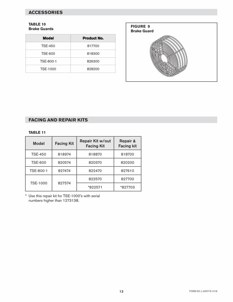
TABLE 10 Brake Guards
TABLE 11
ACCESSORIES
FIGURE 9 Brake Guard
ledoM ledoM ledoM ledoM ledoM .oNtcudorP .oNtcudorP .oNtcudorP .oNtcudorP .oNtcudorP
054-EST 007718
006-EST 003818
1-008-EST 003628
0001-EST 002828
* Use this repair kit for TSE-1000's with serial numbers higher than 1273138.
Model Facing Kit Repair Kit w/out Facing Kit
Repair & Facing kit
TSE-450 818974 818870 818700
TSE-600 820574 820370 820200
TSE-800-1 827474 822470 827610
TSE-1000 827574822570 827700
*822571 *827703
14FORM NO. L-20077-X-1018
Nexen Group, Inc.560 Oak Grove ParkwayVadnais Heights, MN 55127
800.843.7445Fax: 651.286.1099www.nexengroup.com
ISO 9001 Certified
WARRANTY
WarrantiesNexen warrants that the Products will (a) be free from any defects in material or workmanship for a period of 12 months from the date of shipment, and (b) will meet and perform in accordance with the specifications in any engineering drawing specifically for the Product that is in Nexen’s current product catalogue, or that is accessible at the Nexen website, or that is attached to this Quotation and that specifically refers to this Quotation by its number, subject in all cases to any limitations and exclusions set out in the drawing. NEXEN MAKES NO OTHER WARRANTY, EXPRESS OR IMPLIED, AND ALL IMPLIED WARRANTIES, INCLUDING WITHOUT LIMITATION, IMPLIED WARRANTIES OF MERCHANTABILITY AND FITNESS FOR A PARTICULAR PURPOSE ARE HEREBY DISCLAIMED. This warranty applies only if: (a) the Product has been installed, used and maintained in accordance with any applicable Nexen installation or maintenance manual for the Product; (b) the alleged defect is not attributable to normal wear and tear; (c) the Product has not been altered, misused or used for purposes other than those for which it was intended; and (d) Buyer has given written notice of the alleged defect to Nexen, and delivered the allegedly defective Product to Nexen, within one year of the date of shipment.
Exclusive RemedyThe exclusive remedy for the Buyer for any breach of any warranties provided in connection with this agreement will be, at the election of Nexen: (a) repair or replacement with new, serviceably used, or reconditioned parts or products; or (b) issuance of credit in the amount of the purchase price paid to Nexen by the Buyer for the Products.
Agent's AuthorityBuyer agrees that no agent, employee or representative of Nexen has authority to bind Nexen to any affirmation, representation, or warranty concerning the Products other than those warranties expressly set forth herein.
Limitation on Nexen’s LiabilityTO THE EXTENT PERMITTED BY LAW NEXEN SHALL HAVE NO LIABILITY TO BUYER OR ANY OTHER PERSON FOR INCIDENTAL DAMAGES, SPECIAL DAMAGES, CONSEQUENTIAL DAMAGES OR OTHER DAMAGES OF ANY KIND OR NATURE WHATSOEVER, WHETHER ARISING OUT OF BREACH OF WARRANTY OR OTHER BREACH OF CONTRACT, NEGLIGENCE OR OTHER TORT, OR OTHERWISE, EVEN IF NEXEN SHALL HAVE BEEN ADVISED OF THE POSSIBILITY OR LIKELIHOOD OF SUCH POTENTIAL LOSS OR DAMAGE. For all of the purposes hereof, the term "consequential damages" shall include lost profits, penalties, delay damages, liquidated damages or other damages and liabilities which Buyer shall be obligated to pay or which Buyer may incur based upon, related to or arising out of its contracts with its customers or other third parties. In no event shall Nexen be liable for any amount of damages in excess of amounts paid by Buyer for Products or services as to which a breach of contract has been determined to exist. The parties expressly agree that the price for the Products and the services was determined in consideration of the limitation on damages set forth herein and such limitation has been specifically bargained for and constitutes an agreed allocation of risk which shall survive the determination of any court of competent jurisdiction that any remedy herein fails of its essential purpose.
InspectionBuyer shall inspect all shipments of Products upon arrival and shall notify Nexen in writing, of any shortages or other failures to conform to these terms and conditions which are reasonably discoverable upon arrival without opening any carton or box in which the Products are contained. Such notice shall be sent within 14 days following arrival. All notifications shall be accompanied by packing slips, inspection reports and other documents necessary to support Buyer's claims. In addition to the foregoing obligations, in the event that Buyer receives Products that Buyer did not order, Buyer shall return the erroneously shipped Products to Nexen within thirty (30) days of the date of the invoice for such Products; Nexen will pay reasonable freight charges for the timely return of the erroneously shipped Products, and issue a credit to Buyer for the returned Products at the price Buyer paid for them, including any shipping expenses that Nexen charged Buyer. All shortages, overages and nonconformities not reported to Nexen as required by this section will be deemed waived.
Limitation on ActionsNo action, regardless of form, arising out of any transaction to which these terms and conditions are applicable may be brought by the Buyer more than one year after the cause of action has accrued.