MODELS BTN 120 THRU 400/A Series 108 - A. O. … MODELS BTN 120 THRU 400/A Series 108 COMMERCIAL...
32
MODELS BTN 120 THRU 400/A Series 108 COMMERCIAL GAS, GLASS-LINED, TANK-TYPE WATER HEATER • INSTALLATION • OPERATION • MAINTENANCE • LIMITED WARRANTY PLACE THESE INSTRUCTIONS ADJACENT TO HEATER AND NOTIFY OWNER TO KEEP FOR FUTURE REFERENCE. Printed in U.S.A. 0603 PART NO. 195714-000 A DIVISION OF A. O. SMITH CORPORATION McBEE, SOUTH CAROLINA, USA www.hotwater.com CAUTION TEXT PRINTED OR OUTLINED IN RED CONTAINS INFORMATION RELATIVE TO YOUR SAFETY. PLEASE READ THOROUGHL Y BEFORE INST ALLING AND USING THIS APPLIANCE. Thank you for buying this energy efficient water heater from A.O. Smith Water Products Company. We appreciate your confidence in our products.
Transcript of MODELS BTN 120 THRU 400/A Series 108 - A. O. … MODELS BTN 120 THRU 400/A Series 108 COMMERCIAL...

1
MODELS BTN 120 THRU 400/A Series 108COMMERCIAL GAS, GLASS-LINED, TANK-TYPE WATER HEATER
• INSTALLATION • OPERATION • MAINTENANCE • LIMITED WARRANTY
PLACE THESE INSTRUCTIONS ADJACENT TO HEATERAND NOTIFY OWNER TO KEEP FOR FUTURE REFERENCE.
Printed in U.S.A. 0603 PART NO. 195714-000
A DIVISION OF A. O. SMITH CORPORATIONMcBEE, SOUTH CAROLINA, USA
www.hotwater.com
CAUTIONTEXT PRINTED OR OUTLINED IN RED CONTAINSINFORMATION RELATIVE TO YOUR SAFETY. PLEASE READTHOROUGHLY BEFORE INSTALLING AND USING THISAPPLIANCE.
Thank you for buying this energy efficient water heater fromA.O. Smith Water Products Company. We appreciate yourconfidence in our products.

2
ROUGH-IN-DIMENSIONS
FRONT VIEW TOP VIEW BACK VIEW
TANK APPROX U.S Gallons/Hr. and Litres/Hr at TEMPERATURE RISE INDICATED CAPACITY EFF. F° 36F° 40F° 50F° 54F° 60F° 70F° 72F° 80F° 90F° 100F° 108F° 110F° 120F° 126F° 130F° 140F°
Model Btuh KW U.S.Gal. Litres % C° 20C° 22C° 28C° 30C° 33C° 39C° 40C° 44C° 50C° 56C° 60C° 61C° 67C° 70C° 72C° 78C°BTN-120 120,000 71 80 GPH 320 288 239 213 192 164 160 144 128 115 107 105 96 91 89 82
35 269 LPH 1210 1089 871 807 726 622 605 545 484 436 403 396 363 346 335 311BTN-154 154,000 81 80 GPH 410 369 295 274 246 211 205 185 184 148 137 134 123 117 114 106
45 307 LPH 1553 1398 1118 1036 932 79 777 699 621 559 518 508 466 444 430 399BTN-180 180,000 100 80 GPH 480 432 345 320 288 247 240 218 192 173 160 157 144 137 133 123
53 307 LPH 1815 1634 1307 1210 1089 934 908 817 726 654 805 594 545 519 503 487BTN-199 199,000 100 80 GPH 530 477 382 353 318 273 265 239 212 191 177 174 159 151 147 136
58 307 LPH 2007 1806 1445 1338 1204 1032 1004 903 803 723 669 657 602 573 556 516BTN-200 199,000 100 80 GPH 530 477 382 353 318 273 265 239 212 191 177 174 159 151 147 136
58 379 LPH 2007 1806 1445 1338 1204 1032 1004 903 803 723 669 657 602 573 556 516BTN-250 250,000 100 80 GPH 866 600 480 444 400 343 333 300 266 240 222 218 200 190 184 171
73 379 LPH 2522 2269 1815 1881 1513 1297 1261 1135 1009 908 841 825 756 720 698 648BTN-275 275,000 100 80 GPH 733 659 528 488 440 377 366 330 293 264 244 240 220 209 203 188
81 379 LPH 2774 2496 1997 1849 1664 1426 1387 1248 1109 999 925 908 832 792 768 713BTN-310 310,000 85 80 GPH 826 743 595 551 496 425 413 372 330 297 275 270 248 236 229 212
91 322 LPH 3127 2814 2251 2084 1876 1808 1563 1407 1251 1126 1042 1023 938 893 866 804BTN-366 366,000 85 80 GPH 975 878 702 650 585 502 488 439 390 351 325 319 293 279 270 251
107 322 LPH 3692 3322 2658 2461 2215 1898 1846 1661 1477 1329 1231 1208 1107 1055 1022 949BTN-400 390,000 85 80 GPH 1039 935 748 693 624 534 520 468 416 374 346 340 312 297 288 267
114 322 LPH 3934 3540 2832 2622 2360 2023 1967 1770 1573 1416 1311 1287 1180 1124 1089 1011
TABLE 2. RECOVERY CAPACITIES, based on 80% efficiency
Manifold PressureModel Type of Gas Inches vs. W.C. kPa Volts/Hz Amperes
BTN 120-400 Natrual 3.5 0.87 120/60 < 5
FTOP
OUTLET1 1/2” NPT
TOPINLET
1 1/2” NPT
TABLE 3. GAS AND ELECTRICAL CHARACTERISTICS
TABLE 1. ROUGH-IN-DIMENSIONSModel BTN-120 BTN-154 BTN-180 BTN-199 BTN-200 BTN-250 BTN-275 BTN-310 BTN-366 BTN-400Dim. Inches mm Inches mm Inches mm Inches mm Inches mm Inches mm Inches mm Inches mm Inches mm Inches mm
A 63 1800 68 1727 72 1829 72 1829 72 1829 72 1829 72 1829 73 1854 73 1854 73 1854B 4 1/4 108 4 1/2 114 4 1/2 114 4 1/2 114 4 1/2 114 4 1/2 114 4 1/2 114 4 1/2 114 4 1/2 114 4 1/2 114C 59 1/2 1511 62 1575 70 1778 70 1778 70 1778 70 1778 70 1778 72 1829 72 1829 72 1829D 50 7/8 1292 53 5/8 1362 61 5/8 1565 61 5/8 1565 61 5/8 1565 61 5/8 1565 61 5/8 1565 62 1/2 1588 62 1/2 1588 62 1/2 1588E 19 11/16 500 20 1/2 521 20 1/2 521 20 1/2 521 20 1/2 521 20 1/2 521 20 1/2 521 20 1/2 521 22 1/2 572 22 1/2 572F 19 483 21 533 21 533 21 533 21 533 21 533 21 533 21 533 21 533 21 533G 1/2NPT 1/2NPT 1/2NPT 1/2NPT 1/2NPT 1/2NPT 1/2NPT 1/2NPT 1/2NPT 1/2NPT
(gas inlet)H 51 7/8 1318 54 5/8 1387 61 1549 61 1549 61 1549 61 1549 61 1549 63 1600 63 1600 63 1600I 5 127 6 152 6 152 6 152 6 152 6 152 6 152 6 152 6 152 6 152
(vent dia)J 27 3/4 705 27 3/4 705 27 3/4 705 27 3/4 705 27 3/4 705 27 3/4 705 27 3/4 705 27 3/4 705 27 3/4 705 27 3/4 705K 1 1/2NPT 1 1/2NPT 2NPT 2NPT 2NPT 2NPT 2NPT 1 1/2NPT 1 1/2NPT 1 1/2NPTL 1 1/2NPT 1 1/2NPT 2NPT 2NPT 2NPT 2 NPT 2NPT 2 NPT 1 1/2NPT 1 1/2NPT
Appox.Shipping 400 181 470 213 603 274 603 274 603 274 603 274 603 274 725 329 725 329 725 329Weight lbs. K.g lbs. K.g lbs. K.g lbs. K.g lbs. K.g lbs. K.g lbs. K.g lbs. K.g lbs. K.g lbs. K.gSTD.
Approx.Shipping - - - - - - - - 686 311 686 311 686 211 833 378 833 378 833 378Weight lbs. Kg. lbs. Kg. lbs. Kg. lbs. Kg. lbs. Kg. lbs. Kg.ASME

3
TABLE OF CONTENTSROUGH-IN-DIMENSIONS -------------------------------- 2FOREWORD ------------------------------------------------- 3GENERAL SAFETY INFORMATION -------------------- 4Precautions --------------------------------------------------- 4Grounding Instructions ------------------------------------ 4Chemical Vapor Corrosion ------------------------------- 4Improper Combustion ------------------------------------- 4Extended non-use Periods ------------------------------- 4Insulation Blankets ----------------------------------------- 4High Altitude Installation ---------------------------------- 5FEATURES ---------------------------------------------------- 5High Limit Switch ------------------------------------------- 5Electronic Ignition Control -------------------------------- 5Exhaust Inducer (Blower Assy.) ------------------------- 5-6Circulating Pump ------------------------------------------- 6Dishwashing Machine Requirement ------------------ 6INSTALLATION INSTRUCTIONS ------------------------ 6Required Ability ---------------------------------------------- 6Uncrating ------------------------------------------------------ 6Locating The Heater --------------------------------------- 6-7Levelling ------------------------------------------------------- 7Clearances --------------------------------------------------- 7Hard Water ---------------------------------------------------- 7Air Requirements ------------------------------------------- 7-8Venting --------------------------------------------------------- 8Multiple Heater Manifold ---------------------------------- 8Technical Data Venting ------------------------------------ 9-10Water Line Connections ---------------------------------- 11Water (Potable) Heating and Space Heating ------- 11Thermometers (Not Supplied) -------------------------- 11Relief Valve --------------------------------------------------- 11INSTALLATION DIAGRAMS-TOPINLET/OUTLET USAGE ----------------------------------- 12General -------------------------------------------------------- 12Code Restrictions ------------------------------------------ 12INSTALLATION DIAGRAMS ------------------------------- 13-18MANIFOLD KITS --------------------------------------------- 19Heater Wiring ------------------------------------------------ 20
Gas Piping ---------------------------------------------------- 21Purging -------------------------------------------------------- 21Gas Pressure Regulator ---------------------------------- 21-22OPERATION -------------------------------------------------- 22General -------------------------------------------------------- 22Filling ----------------------------------------------------------- 22SEQUENCE OF OPERATION ---------------------------- 23Lighting and Operation ------------------------------------ 24Water Temperature Control ------------------------------ 25Checking Venting ------------------------------------------- 25PREVENTIVE MAINTENANCE --------------------------- 25Check The Ignitor Assembly ----------------------------- 25Ignitor Assembly -------------------------------------------- 25-26Main Burner --------------------------------------------------- 26Gas Valves ---------------------------------------------------- 26Checking The Input ----------------------------------------- 26Venting System ---------------------------------------------- 27Remote Storage Tank Temperature Control -------- 27Relief Valve --------------------------------------------------- 27Hot Water Odor ---------------------------------------------- 27Anode Rod Inspection ------------------------------------- 27Flushing ------------------------------------------------------- 27Draining ------------------------------------------------------- 27Recommended Procedure For PeriodicRemoval of Lime Deposits From Tank TypeCommercial Water Heaters ------------------------------ 28Deliming Solvents ------------------------------------------ 28Tank Cleanout Procedures ------------------------------- 28-29Ignition Module System ----------------------------------- 29System Diagnostics ---------------------------------------- 29SERVICE ------------------------------------------------------ 29Electrical Servicing ----------------------------------------- 29Replacement Parts, Service Handbooksand Training Aids ------------------------------------------- 30Sequence of Operation Flow Chart -------------------- 30Operational Checklist -------------------------------------- 31Limited Warranty -------------------------------------------- 32
Page Page
FOREWORDThese designs comply with ANSI Z21.10.3 as an automaticcirculating or automatic storage tank type water heater.
Heaters having an input of 310,000, 366,000, 390,000 Btuh witha recovery rating of 277.3 gph or more also comply with ANSIZ21.10.3 as an automatic instantaneous type heater.
Detailed installation diagrams are found in this manual. Thesediagrams will serve to provide the installer with a reference forthe materials and methods of piping necessary. It is highlyessential that all water, gas piping and wiring be installed asshown on the diagrams.
Particular attention should be given to the installation ofthermometers at the locations indicated on the diagrams asthese are necessary for checking the proper functioning of theheater.
The heater is designed to operate on natural gas only. If youhave obtained this heater for use on propane-STOP. Do not
install this water heater. Immediately call your supplier to correctthe situation.
These heaters may be installed on combustible floors.
In addition to these instructions, the equipment shall be installedin accordance with those installation regulations in force in thelocal area where the installation is to be made. These shall becarefully followed in all cases. Authorities having jurisdictionshould be consulted before installations are made.
The installation must conform to these instructions and the localcode authority having jurisdiction. In the absence of local codes,the installation must comply with the latest editions of theNational Fuel Gas Code, ANSI Z223.1/NFPA 54 and the NationalElectrical Code, NFPA 70, documents are available from theNational Fire Protection Association, 1 Batterymarch Park, Quincy,MA 02269.
4
GENERAL SAFETYINFORMATION
PRECAUTIONS
DO NOT USE THIS APPLIANCE IF ANY PART HAS BEEN UNDERWATER. Immediately call a qualified service technician to inspectthe appliance and to replace any part of the control system andany gas control which has been under water.
IF THE UNIT IS EXPOSED TO THE FOLLOWING, DO NOTOPERATE HEATER UNTIL ALL CORRECTIVE STEPS HAVEBEEN MADE BY A QUALIFIED SERVICEMAN.
1. EXTERNAL FIRE.
2. DAMAGE.
3. FIRING WITHOUT WATER.
4. SOOTING
GROUNDING INSTRUCTIONS
This water heater must be grounded in accordance with theNational Electric Code and/or local codes. These must befollowed in all cases.
This water heater must be connected to a grounded metal,permanent wiring system; or an equipment grounding conductormust be run with the circuit conductors and connected to theequipment grounding terminal or lead on the water heater, seeFigure 9.
CHEMICAL VAPOR CORROSION
WARNINGCORROSION OF THE FLUEWAYS AND VENT SYSTEM MAYOCCUR IF AIR FOR COMBUSTION CONTAINS CERTAINCHEMICAL VAPORS. SUCH CORROSION MAY RESULT INFAILURE AND RISK OF ASPHYXIATION.
Spray can propellants, cleaning solvents, refrigerator and airconditioning refrigerants, swimming pool chemicals, calciumand sodium chloride (water softener salt), waxes, and processchemicals and typical compounds which are potentiallycorrosive. Do not store products of this sort near the heater.Also, air which is brought in contact with a the heater should notcontain any of these chemicals. If necessary, uncontaminatedair should be obtained from remote or outside sources. Thelimited warranty is voided when failure of water heater is due toa corrosive atmosphere. (Refer to the limited warranty forcomplete terms and conditions.
IMPROPER COMBUSTION
WARNINGATTIC AND/OR EXHAUST FANS OPERATING ON THEPREMISES WITH A WATER HEATER CAN RESULT IN CARBONMONOXIDE POISONING AND DEATH.
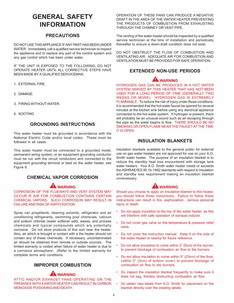
OPERATION OF THESE FANS CAN PRODUCE A NEGATIVEDRAFT IN THE AREA OF THE WATER HEATER PREVENTINGTHE PRODUCTS OF COMBUSTION FROM EXHAUSTINGTHROUGH THE CHIMNEY OR VENT PIPE.
The venting of the water heater should be inspected by a qualifiedservice technician at the time of installation and periodicallythereafter to ensure a down-draft condition does not exist.
DO NOT OBSTRUCT THE FLOW OF COMBUSTION ANDVENTILATING AIR. ADEQUATE AIR FOR COMBUSTION ANDVENTILATION MUST BE PROVIDED FOR SAFE OPERATION.
EXTENDED NON-USE PERIODS
WARNINGHYDROGEN GAS CAN BE PRODUCED IN A HOT WATERSYSTEM SERVED BY THIS HEATER THAT HAS NOT BEENUSED FOR A LONG PERIOD OF TIME (GENERALLY TWOWEEKS OR MORE). HYDROGEN GAS IS EXTREMELYFLAMMABLE. To reduce the risk of injury under these conditions,it is recommended that the hot water faucet be opened for severalminutes at the kitchen sink before using any electrical applianceconnected to the hot water system. If hydrogen is present, therewill probably be an unusual sound such as air escaping throughthe pipe as the water begins to flow. THERE SHOULD BE NOSMOKING OR OPEN FLAME NEAR THE FAUCET AT THE TIMEIT IS OPEN.
INSULATION BLANKETS
Insulation blankets available to the general public for externaluse on gas water heaters are not approved for use on your A.O.Smith water heater. The purpose of an insulation blanket is toreduce the standby heat loss encountered with storage tankwater heaters. Your A.O. Smith water heater meets or exceedsthe ASHRAE/IES 90.1b-1992 standards with respect to insulationand standby loss requirement making an insulation blanketunnecessary.
WARNINGShould you choose to apply an insulation blanket to this heater,you should follow these instructions. Failure to follow theseinstructions can result in fire, asphyxiation , serious personalinjury or death.
• Do not apply insulation to the top of the water heater, as thiswill interfere with safe operation of exhaust inducer.
• Do not cover gas valve on the temperature & pressure reliefvalve.
• Do not cover the instruction manual. Keep it on the side ofthe water heater or nearby for future reference.
• Do not allow insulation to come within 2” (5cm) of the burner,to prevent blockage of combustion air flow to the burners.
• Do not allow insulation to come within 9” (23cm) of the floor,(within 2” (5cm) of bottom cover) to prevent blockage ofcombustion air flow to the burners.
• Do inspect the insulation blanket frequently to make sure itdoes not sag, thereby obstructing combustion air flow.
• Do obtain new labels from A.O. Smith for placement on theblanket directly over the existing labels.

5
HIGH ALTITUDE INSTALLATIONS
WARNINGINSTALLATIONS ABOVE 2000 FEET (610 METERS) REQUIREREPLACEMENT OF THE BURNER ORIFICE IN ACCORDANCEWITH SECTION 8.1.2 OF THE NATIONAL FUEL GAS CODE (ANSIZ223.1). FAILURE TO REPLACE THE ORIFICE WILL RESULTIN IMPROPER AND INEFFICIENT OPERATION OF THEAPPLIANCE RESULTING IN THE PRODUCTION OFINCREASED LEVELS OF CARBON MONOXIDE GAS IN EXCESSOF SAFE LIMITS WHICH COULD RESULT IN SERIOUSPERSONAL INJURY OR DEATH.
You should contact your gas supplier for any specific changeswhich may be required in your area.
As elevation above sea level is increased, there is less oxygenper cubic foot of air. Therefore, the heater input rate should bereduced at high altitudes for satisfactory operation with thereduced oxygen supply. Failure to make this reduction wouldresult in an overfiring of the heater causing sooting, poorcombustion and/or unsatisfactory heater performance.
REQUIREMENTSRatings specified by manufacturers for most appliances applyfor elevations up to 2000 feet. For elevations above 2000 feet,ratings must be reduced at the rate of 4% for each 1000 feetabove sea level. For example, if a heater is rated at 120,000Btuh at sea level, to rate the heater at 4000 feet, you subtract 4(once for each thousand feet) x.04 (4% input reduction) x 120,000Btuh (original rating) from the original rating. Therefore, tocalculate the input rating at 4,000 feet: 4 x .04 x 120,000 =19,200Btuh, 120,000 - 19,200 = 100,800 Btuh. At 6000 feet the correctinput rating should be 91,200 Btuh.
The input reduction is primarily achieved by reducing the size ofthe main burner orifices. To do this, the main burner orificesrequire replacement with orifices sized for the particularinstallation elevation. Correct orifice sizing and parts may beobtained from A.O. Smith Water Products Company. Whenordering, be sure to state the model number and the altitude ofthe location where the water heater is being installed.
Upon completion of derating of the heater, adjustment to the gaspressure regulator may be required. See CHECKING THEINPUT section in this manual for inlet and manifold pressurerequirements.
Also due to the input rating reduction required at high altitudes,the output rating of the appliance is also reduced and should becompensated for in the sizing of the equipment for application.
FEATURES
HIGH LIMIT SWITCH
The digital thermostat (Fig. 2) contains the high limit (energycutoff) sensor. The high limit switch interrupts main burner gasflow should the water temperature reach 203°F (95°C).
In the event of high limit switch operation, the appliance cannotbe restarted unless the water temperature is reduced toapproximately 120°F (49°C). The high limit reset button on thefront of the control then needs to be depressed.
Continued manual resetting of high limit control, preceded byhigher than usual water temperature is evidence of high limitswitch operation. The following is a possible reason for highlimit switch operation:
• A malfunction in the thermostatic controls would allow thegas valve to remain open causing water temperature to exceedthe thermostat setting. The water temperature would continueto rise until high limit switch operation.
Contact your dealer or service agent if continued high limit switchoperation occurs.
DIGITAL THERMOSTATFIGURE 2
ELECTRONIC IGNITION CONTROLEach heater is equipped with a ignition module. The solid sateignition control (Fig. 3), ignites the main burner by utilizing asilicone nitride ignitor. The silicone nitride ignitor shuts off duringthe heating cycle and the main burner flame is sensed througha remote flame sensor integral to the silicone nitride ignitorassembly. The ignition control will try to ignite the main burnerthree times before lockout. Then it waits one hour before tryingagain to ignite the main burners. This is a continuous cycle.
IGNITION CONTROL BOARDFIGURE 3
EXHAUST INDUCER (BLOWER ASSY.)All BTN 120-400 models are equipped with an exhaust inducer.The inducer assists in drawing in fresh air to the unit forcombustion and then assists in dispensing the combustion by-products into the venting leading outside.

6
The exhaust inducer is equipped with a gravity controlled damperto reduce the amount of heat loss through the flue, improvingefficiency.
EXHAUST INDUCERFIGURE 4
CIRCULATING PUMP
A circulating pump is used when a system requires a circulatingloop or there is a storage tank used in conjunction with theheater. Refer to the piping diagrams in this manual for electricalhookup information and install in accordance with the latestversion of the National Electric Code ANSI/NFPA No. 70.
Only all bronze circulators are used with commercial waterheaters.
Although circulators are oiled and operated by the manufacturersome circulators must be oiled again before operating. Pleaserefer to manufacturer’s instructions.
DISHWASHING MACHINE REQUIREMENT
These appliances meet the National Sanitation FoundationStandard for sanitary installations when used with the followingleg kit, Part No. 6570-7.
All dishwashing machines meeting the National SanitationFoundation requirements are designed to operate with waterflow pressures between 15 and 25 psi. Flow pressures above25 psi, or below 15 psi, will result in improperly sanitized dishes.Where pressures are high, a water pressure reducing or flowregulating control valve should be used in 1800F line to thedishwashing machine, and should be adjusted to deliver waterbetween these limits.
The National Sanitation Foundation also recommendscirculation of 1800F water. Where this is done, the circulationshould be very gentle so that it does not cause any unnecessaryturbulence inside the water heater. The circulation should bejust enough to provide 1800F water at the point of take-off to thedishwashing machine. Adjust flow by means of the plug cock inthe circulating line.
INSTALLATION INSTRUCTIONSREQUIRED ABILITY
INSTALLATION OR SERVICE OF THIS WATER HEATERREQUIRES ABILITY EQUIVALENT TO THAT OF A LICENSEDTRADESMAN IN THE FIELD INVOLVED. PLUMBING, AIR
SUPPLY, VENTING, GAS SUPPLY AND ELECTRICAL WORK AREREQUIRED.
WARNINGFAILURE TO FOLLOW THESE INSTRUCTIONS CAN RESULTIN SERIOUS PERSONAL INJURY OR DEATH.
UNCRATING
The heater is shipped with the inducer already installed. Thewiring conduit runs from the thermostat to the inducer. Beforeturning unit on, check to make sure the wiring conduit is securelyplugged into the inducer.
LOCATING THE HEATER
When installing the heater, consideration must be given to properlocation. Location selected should be as close to the stack orchimney as practicable, with adequate air supply and ascentralized with the piping system as possible.
WARNINGTHERE IS A RISK IN USING FUEL BURNING APPLIANCESSUCH AS GAS WATER HEATERS IN ROOMS, GARAGES OROTHER AREAS WHERE GASOLINE, OTHER FLAMMABLELIQUIDS OR ENGINE DRIVEN EQUIPMENT OR VEHICLES ARESTORED, OPERATED OR REPAIRED. FLAMMABLE VAPORSARE HEAVY AND TRAVEL ALONG THE FLOOR AND MAY BEIGNITED BY THE HEATER’S PILOT OR MAIN BURNER FLAMESCAUSING FIRE OR EXPLOSION. SOME LOCAL CODES PERMITOPERATION OF GAS APPLIANCES IN SUCH AREAS IF THEYARE INSTALLED 18” OR MORE ABOVE THE FLOOR. THIS MAYREDUCE THE RISK IF LOCATION IN SUCH AN AREA CANNOTBE AVOIDED.
DO NOT INSTALL THIS WATER HEATER DIRECTLY ON ACARPETED FLOOR. A FIRE HAZARD MAY RESULT. Instead thewater heater must be placed on a metal or wood panel extendingbeyond the full width and depth by at least 3 inches in any direction.If the heater is installed in a carpeted alcove, the entire floorshall be covered by the panel. Also, see the DRAININGrequirements in MAINTENANCE Section.
THE HEATER SHALL BE LOCATED OR PROTECTED SO IT ISNOT SUBJECT TO PHYSICAL DAMAGE BY A MOVING VEHICLE.
WARNINGFLAMMABLE ITEMS, PRESSURIZED CONTAINERS OR ANYOTHER POTENTIAL FIRE HAZARDOUS ARTICLES MUSTNEVER BE PLACED ON OR ADJACENT TO THE HEATER. OPENCONTAINERS OR FLAMMABLE MATERIAL SHOULD NOT BESTORED OR USED IN THE SAME ROOM WITH THE HEATER.
THE HEATER MUST NOT BE LOCATED IN AN AREA WHERE ITWILL BE SUBJECT TO FREEZING.
LOCATE IT NEAR A FLOOR DRAIN. THE HEATER SHOULD BELOCATED IN AN AREA WHERE LEAKAGE FROM THE HEATEROR CONNECTIONS WILL NOT RESULT IN DAMAGE TO THEADJACENT AREA OR TO LOWER FLOORS OF THESTRUCTURE.
WHEN SUCH LOCATIONS CANNOT BE AVOIDED, A SUITABLEDRAIN PAN SHOULD BE INSTALLED UNDER THE HEATER.Such pans should be fabricated with sides at least 2" deep, with

7
length and width at least 2" greater than the diameter of theheater and must be piped to an adequate drain. The pan mustnot restrict combustion air flow.
LEVELING
If the unit is not level, insert the bolts which were used in cratinginto the legs to correct this condition.
CLEARANCES
These heaters are approved for installation on combustibleflooring (with Leg Kit #6570-7) in an alcove when the minimumclearance from any combustion construction are followed asindicated in figure 5 and Table 4.
In all installations the minimum combustible clearances fromvent piping shall be 6" (152mm). Vent piping passing through acombustible wall or ceiling must be a continuous run (no joints)and retain the 6" (152mm) clearance unless an approvedreducing thimble is used.
A service clearance of 24" (610mm) should be maintained fromserviceable parts, such as relief valves, flue baffles, thermostats,cleanout openings or drain valves.
The units are approved for installation with side, rear and ceilingclearances as indicated below:
MINIMUM CLEARANCES TO COMBUSTIBLES IN INCHES (mm)MODEL ”A” ”B” ”C” ”D”
RIGHT LEFT BACK CEILINGSIDE SIDE
BTN-120 2” (51mm) 2” (51mm) 2” (51mm) 12” (305mm)BTN-154 2” (51mm) 2” (51mm) 2” (51mm) 12” (305)BTN-180 2” (51mm) 2” (51mm) 2” (51mm) 12” (305)BTN-199 2” (51mm) 2” (51mm) 2” (51mm) 12” (305)
BTN-200/A 2” (51mm) 2” (51mm) 2” (51mm) 12” (305)BTN-250/A 2” (51mm) 2” (51mm) 2” (51mm) 12” (305)BTN-275/A 2” (51mm) 2” (51mm) 2” (51mm) 12” (305)BTN-310/A 3” (76mm) 3” (76mm) 3” (76mm) 12” (305)BTN-366/A 6” (152mm) 6” (152mm) 6” (152mm) 12” (305)BTN-400/A 3” (76mm) 3” (76mm) 3” (76mm) 12” (305)
TABLE 4
CLEARANCES TO NONCOMBUSTION CONSTRUCTIONMODEL ”A” ”B” ”C” ”D”
RIGHT LEFT BACK CEILINGSIDE SIDE
BTN-120 0 0 0 12” (305mm)BTN-154 0 0 0 12” (305mm)BTN-180 0 0 0 12” (305mm)BTN-199 0 0 0 12” (305mm)
BTN-200/A 0 0 0 12” (305mm)BTN-250/A 0 0 0 12” (305mm)BTN-275/A 0 0 0 12” (305mm)BTN-310/A 6” (152mm) 6” (152mm) 6” (152mm) 12” (305mm)BTN-366/A 0 0 0 12” (305mm)BTN-400/A 0 0 0 12” (305mm)
TABLE 5HARD WATER
Where hard water conditions exist, water softening or thethreshold type of water treatment is recommended. This willprotect the dishwashers, coffee urns, water heaters, water pipingand other equipment.
See MAINTENANCE section for details of tank cleanoutprocedure.
AIR REQUIREMENTS
REFER TO THE LATEST EDITION OF THE "NATIONAL FUELGAS CODE" ANSI Z223.1/NFPA 54.
KEEP APPLIANCE AREA CLEAR AND FREE OF COMBUSTIBLEMATERIALS, GASOLINE AND OTHER FLAMMABLES, VAPORSAND LIQUIDS.
DO NOT OBSTRUCT THE FLOW OF COMBUSTION ORVENTILATING AIR.
WARNINGFOR SAFE OPERATION PROVIDE ADEQUATE AIR FORCOMBUSTION AND VENTILATION. AN INSUFFICIENT SUPPLYOF AIR WILL CAUSE RECIRCULATION OF COMBUSTIONPRODUCTS RESULTING IN AIR CONTAMINATION THAT MAYBE HAZARDOUS TO LIFE. SUCH A CONDITION OFTEN WILLRESULT IN A YELLOW, LUMINOUS BURNER FLAME, CAUSINGCARBONING OR SOOTING OF THE COMBUSTION CHAMBER,
ILLUSTRATION OF MINIMUM COMBUSTIBLE CLEARANCES IN AN ALCOVE - FIGURE 5
8
BURNERS AND FLUE TUBES AND CREATES A RISK OFASPHYXIATION.
Where an exhaust fan is supplied in the same room with aheater, sufficient openings for air must be provided in the walls.UNDERSIZED OPENINGS WILL CAUSE AIR TO BE DRAWNINTO THE ROOM THROUGH THE CHIMNEY, CAUSING POORCOMBUSTION. SOOTING MAY RESULT IN SERIOUS DAMAGETO THE HEATER AND RISK OF FIRE OR EXPLOSION.
UNCONFINED SPACE
In buildings of conventional frame, brick, or stone construction,unconfined spaces may provide adequate air for combustion,ventilation and draft hood dilution.
If the unconfined space is within a building of tight construction(buildings using the following construction: weather stripping,heavy insulation, caulking, vapor barrier, etc.), air for combustion,ventilation and draft hood dilution must be obtained fromoutdoors. The installation instructions for confined spaces intightly constructed buildings must be followed to ensureadequate air supply.
CONFINED SPACE
When drawing combustion and dilution air from inside aconventionally constructed building to a confined space, such aspace shall be provided with two permanent openings, ONE INOR WITHIN 12 INCHES (30.5cm) OF THE ENCLOSURE TOPAND ONE IN OR WITHIN 12 INCHES (30.5cm) OF THEENCLOSURE BOTTOM. Each opening shall have a free area ofat least one square inch per 1000 Btuh (2,225mm2/Kw) of thetotal input of all appliances in the enclosure, but not less than100 square inches (645 square cm).
If the confined space is within a building of tight construction, airfor combustion, ventilation, and drafthood dilution must beobtained from outdoors. When directly communicating with theoutdoors or communicating with the outdoors through verticalducts, two permanent openings, located in the above manner,shall be provided. Each opening shall have a free area of notless than one square inch per 4000 Btuh (8,900mm2/Kw)of thetotal input of all appliances in the enclosure. If horizontal ductsare used, each opening shall have a free area of not less thanone square inch per 2000 Btuh (4,450mm2/Kw)of the total inputof all appliances in the enclosure.
VENTING
WARNINGTHE INSTRUCTIONS IN THIS SECTION ON VENTING MUSTBE FOLLOWED TO AVOID CHOKED COMBUSTION ORRECIRCULATION OF FLUE GASES. SUCH CONDITIONSCAUSE SOOTING OR RISKS OF FIRE AND ASPHYXIATION.
Heater must be protected from freezing downdrafts.
Remove all soot or other obstructions from the chimney that willretard a free draft.
Type B venting is recommended with these heaters. For typicalventing application see TECHNICAL DATA VENTING on pages9 and 10.
This water heater must be vented in compliance with all localcodes, the current revision of the National Fuel Gas Code (ANSI-Z223.1) and with the Category I Venting Tables.
If any part of the vent system are exposed to ambienttemperatures below 40°F it must be insulated to preventcondensation.
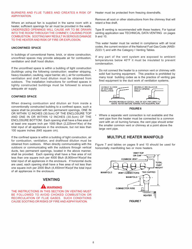
• Do not connect the heater to a common vent or chimney withsolid fuel burning equipment. This practice is prohibited bymany local building codes as is the practice of venting gasfired equipment to the duct work of ventilation systems.
FIGURE 6
• Where a separate vent connection is not available and thevent pipe from the heater must be connected to a commonvent with an oil burning furnace, the vent pipe should enterthe smaller common vent or chimney at a point above thelarge vent pipe.
MULTIPLE HEATER MANIFOLD
Figure 7 and tables on pages 9 and 10 should be used forhorizontally manifolding two or more heaters.
FIGURE 7

9
TYPE B GAS VENTMultiple Gas Fired Tank-Type Heaters
When venting multiple tank type heaters using Type Bvent pipe, follow the installation diagram (figure 4) andtables below which give sizing and data based uponNFPA 54/ANSI Z223. 1992.
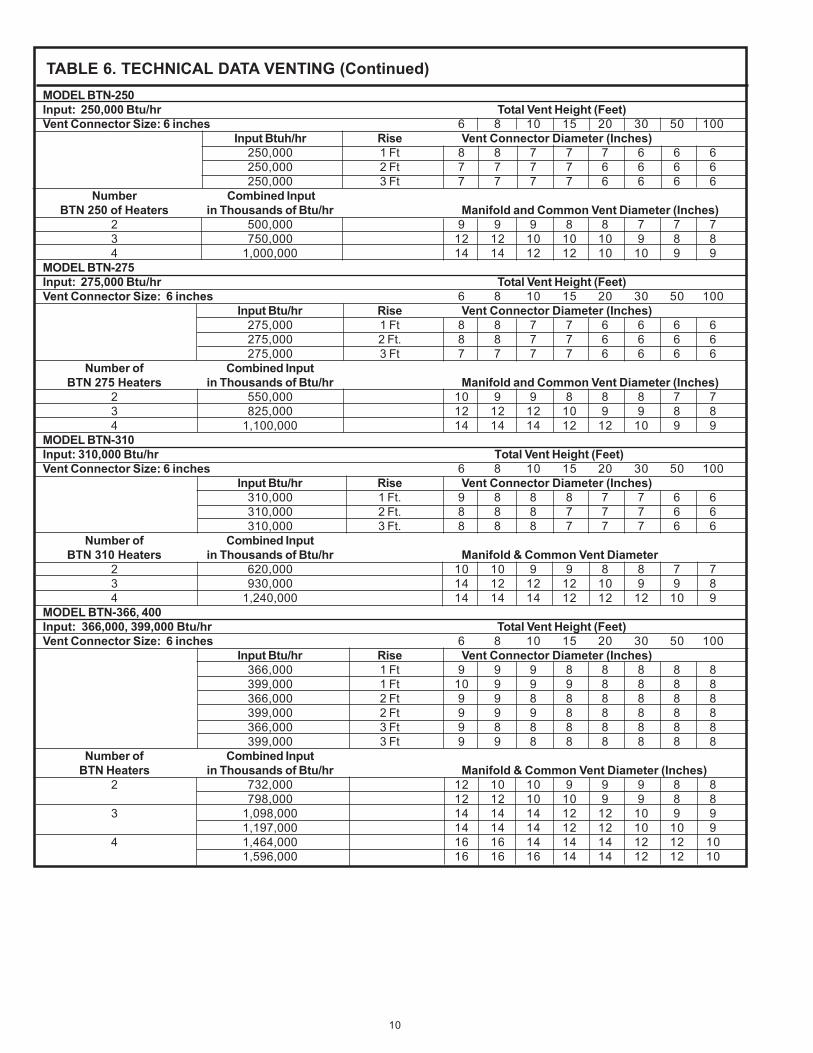
TABLE 6. TECHNICAL DATA VENTING
MODEL BTN-120Input: 120,000 Btu/hr Total Vent Height (Feet)Vent Connector Size: 5 inches 6 8 10 15 20 30 50 100
Input Btu/hr Rise Vent Connector Diameter (Inches)120,000 1 Ft. 6 6 5 5 5 5 5 5120,000 2 Ft. 5 5 5 5 5 5 5 5120,000 3 Ft. 5 5 5 5 5 5 5 5
Number of Combined InputBTN 120 Heaters in Thousands of Btu/hr Manifold and Common Vent Diameter (Inches)
2 240,000 7 7 6 6 6 6 6 63 360,000 8 8 7 7 7 6 6 64 480,000 9 9 9 8 8 7 7 6
MODEL BTN-154Input: 154,000 Btu/hr Total Vent Height (Feet)Vent Connector Size: 6 inches 6 8 10 15 20 30 50 100
Input Btu/hr Rise Vent Connector Diameter (Inches)154,000 1 Ft. 6 6 6 6 6 6 6 6154,000 2 Ft. 6 6 6 6 6 6 6 6154,000 3 Ft. 6 6 6 6 6 6 6 6
Number of Combined InputBTN 154 Heaters in Thousands of Btu/hr Manifold and Common Vent Diameter (Inches)
2 308,000 7 7 6 6 6 6 6 63 462,000 8 8 7 7 7 6 6 64 616,000 9 9 9 8 8 7 7 6
MODEL BTN-180,199, 200Input: 180,000, 190,000 and 199,000 Btu/hr Total Vent Height (Feet)Vent Connector Size: 6 inches 6 8 10 15 20 30 50 100
Input Btuh/hr Rise Vent Connector Diameter (Inches)180,000 1 Ft. 7 7 6 6 6 6 6 6190,000 1 Ft. 7 7 7 6 6 6 6 6199,000 1 Ft. 7 7 7 6 6 6 6 6180,000 2 Ft. 6 6 6 6 6 6 6 6190,000 2 Ft. 7 6 6 6 6 6 6 6199,000 2 Ft. 7 7 6 6 6 6 6 6180,000 3 Ft. 6 6 6 6 6 6 6 6190,000 3 Ft. 6 6 6 6 6 6 6 6199,000 3 Ft. 6 6 6 6 6 6 6 6
Number of Combined InputBTN Heaters in Thousands of Btu/hr Manifold & Common Vent Diameter (Inches)
360,000 7 7 6 6 6 6 6 62 380,000 7 7 7 6 6 6 6 6
398,000 6 7 7 6 6 6 6 6540,000 7 6 6 6 6 6 6 6
3 570,000 7 6 6 6 6 6 6 6597,000 6 7 6 6 6 6 6 6720,000 6 6 6 6 6 6 6 6
4 760,000 6 6 6 6 6 6 6 6796,000 6 6 6 6 6 6 6 6
10
MODEL BTN-250Input: 250,000 Btu/hr Total Vent Height (Feet)Vent Connector Size: 6 inches 6 8 10 15 20 30 50 100
Input Btuh/hr Rise Vent Connector Diameter (Inches)250,000 1 Ft 8 8 7 7 7 6 6 6250,000 2 Ft 7 7 7 7 6 6 6 6250,000 3 Ft 7 7 7 7 6 6 6 6
Number Combined InputBTN 250 of Heaters in Thousands of Btu/hr Manifold and Common Vent Diameter (Inches)
2 500,000 9 9 9 8 8 7 7 73 750,000 12 12 10 10 10 9 8 84 1,000,000 14 14 12 12 10 10 9 9
MODEL BTN-275Input: 275,000 Btu/hr Total Vent Height (Feet)Vent Connector Size: 6 inches 6 8 10 15 20 30 50 100
Input Btu/hr Rise Vent Connector Diameter (Inches)275,000 1 Ft 8 8 7 7 6 6 6 6275,000 2 Ft. 8 8 7 7 6 6 6 6275,000 3 Ft 7 7 7 7 6 6 6 6
Number of Combined InputBTN 275 Heaters in Thousands of Btu/hr Manifold and Common Vent Diameter (Inches)
2 550,000 10 9 9 8 8 8 7 73 825,000 12 12 12 10 9 9 8 84 1,100,000 14 14 14 12 12 10 9 9
MODEL BTN-310Input: 310,000 Btu/hr Total Vent Height (Feet)Vent Connector Size: 6 inches 6 8 10 15 20 30 50 100
Input Btu/hr Rise Vent Connector Diameter (Inches)310,000 1 Ft. 9 8 8 8 7 7 6 6310,000 2 Ft. 8 8 8 7 7 7 6 6310,000 3 Ft. 8 8 8 7 7 7 6 6
Number of Combined InputBTN 310 Heaters in Thousands of Btu/hr Manifold & Common Vent Diameter
2 620,000 10 10 9 9 8 8 7 73 930,000 14 12 12 12 10 9 9 84 1,240,000 14 14 14 12 12 12 10 9
MODEL BTN-366, 400Input: 366,000, 399,000 Btu/hr Total Vent Height (Feet)Vent Connector Size: 6 inches 6 8 10 15 20 30 50 100
Input Btu/hr Rise Vent Connector Diameter (Inches)366,000 1 Ft 9 9 9 8 8 8 8 8399,000 1 Ft 10 9 9 9 8 8 8 8366,000 2 Ft 9 9 8 8 8 8 8 8399,000 2 Ft 9 9 9 8 8 8 8 8366,000 3 Ft 9 8 8 8 8 8 8 8399,000 3 Ft 9 9 8 8 8 8 8 8
Number of Combined InputBTN Heaters in Thousands of Btu/hr Manifold & Common Vent Diameter (Inches)
2 732,000 12 10 10 9 9 9 8 8798,000 12 12 10 10 9 9 8 8
3 1,098,000 14 14 14 12 12 10 9 91,197,000 14 14 14 12 12 10 10 9
4 1,464,000 16 16 14 14 14 12 12 101,596,000 16 16 16 14 14 12 12 10
TABLE 6. TECHNICAL DATA VENTING (Continued)

11
WATER LINE CONNECTIONS
This manual provides detailed installation diagrams (see pages13-19 of this manual) for typical methods of application for thewater heater(s).
The water heater may be installed by itself, or with a separatestorage tank, on both single and two-temperature systems.When used with a separate storage tank, the circulation may beeither by gravity or by means of a circulating pump. When acirculating pump is used it is important to note that the flow rateshould be slow so that there will be a minimum of turbulenceinside the heater.
If a water heater is installed in a closed water system, provisionsfor the thermal expansion in the Hot Water System must beprovided. Contact the water supplier or local plumbing inspectoron how to control this situation.
WATER (POTABLE) HEATING AND SPACEHEATING (See pages 13-19)
1. All piping components connected to this unit for space heatingapplications shall be suitable for use with potable water.
2. Toxic chemicals, such as those used for boiler treatment,shall NEVER be introduced into this system.
3. This unit may NEVER be connected to any existing heatingsystem or component(s) previously used with a non-potablewater heating appliance.
4. When the system requires water for space heating attemperatures higher than required for domestic waterpurposes, a tempering valve must be installed. Please referto installation diagrams on pages 16 and 18 of this manualfor suggested piping arrangements.
CAUTIONA closed system will exist if a check valve (without bypass),pressure reducing valve (without bypass), or a water meter(without bypass) is installed in the cold water line between thewater heater and street main (or well).
Excessive pressure may develop in such closed systems,causing premature tank failure or intermittent relief valveoperation. This is not a warranty failure. An expansion tank or asimilar device may be required in the inlet supply line betweenthe appliance and the meter or valve to compensate for thethermal expansion of the water.
SYSTEM CONNECTIONS
The system installation must conform to these instructions andto the local code authority having jurisdiction. Good practicerequires that all heavy piping be supported.
THERMOMETERS (Not Supplied)Thermometers should be obtained and field installed as shownin the installation diagrams.
Thermometers are installed in the system as a means ofdetecting the temperature of the outlet water supply.
RELIEF VALVEThis water heater is equipped with a combination temperature-pressure relief valve that complies with the standard for reliefvalves and automatic gas shutoff devices for hot water supplysystem, ANSI Z21.22. FOR SAFE OPERATION OF THE WATERHEATER, THE RELIEF VALVE(S) MUST NOT BE REMOVED ORPLUGGED.
ASME ratings cover pressure relief capacities. A.G.A. ratingscover release rate with temperature actuation.
In addition to the appliance relief valve, each remote storagetank which may be used in conjunction with this appliance shallalso be installed with a properly sized, rated and approvedcombination temperature (ANSI) and pressure (ASME) reliefvalve(s).
WARNINGTHE PURPOSE OF RELIEF VALVE IS TO AVOID EXCESSIVEPRESSURE OR TEMPERATURE INTO THE STEAM RANGE,WHICH MAY CAUSE SCALDING AT FIXTURES, TANKEXPLOSION, SYSTEM OR HEATER DAMAGE. NO VALVE IS TOBE PLACED BETWEEN THE RELIEF VALVE AND TANK.
Your local code authority may have other specific relief valverequirements.
A DRAIN LINE MUST BE CONNECTED TO THE RELIEF VALVETO DIRECT DISCHARGE TO A SAFE LOCATION TO AVOIDSCALDING OR WATER DAMAGE. THIS LINE MUST NOT BEREDUCED FROM THE SIZE OF THE VALVE OUTLET AND MUSTNOT CONTAIN VALVES, RESTRICTIONS NOR SHOULD IT BELOCATED IN FREEZING AREAS. DO NOT THREAD OR CAPTHE END OF THIS LINE. RESTRICTED OR BLOCKEDDISCHARGE WILL DEFEAT THE PURPOSE OF THE VALVE ANDIS UNSAFE. DISCHARGE LINE SHALL BE INSTALLED TOALLOW COMPLETE DRAINAGE OF BOTH THE VALVE AND LINE.
See SERVICE INFORMATION section for procedure andprecautions.
12
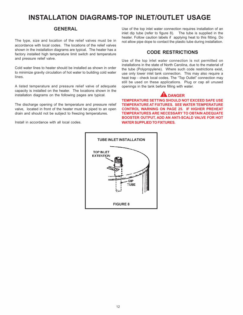
INSTALLATION DIAGRAMS-TOP INLET/OUTLET USAGEUse of the top inlet water connection requires installation of aninlet dip tube (refer to figure 8). The tube is supplied in theheater. Follow caution labels if applying heat to this fitting. Donot allow pipe dope to contact the plastic tube during installation.
CODE RESTRICTIONSUse of the top inlet water connection is not permitted oninstallations in the state of North Carolina, due to the material ofthe tube (Polypropylene). Where such code restrictions exist,use only lower inlet tank connection. This may also require aheat trap - check local codes. The “Top Outlet” connection maystill be used on these applications. Plug or cap all unusedopenings in the tank before filling with water.
DANGERTEMPERATURE SETTING SHOULD NOT EXCEED SAFE USETEMPERATURE AT FIXTURES. SEE WATER TEMPERATURECONTROL WARNING ON PAGE 25. IF HIGHER PREHEATTEMPERATURES ARE NECESSARY TO OBTAIN ADEQUATEBOOSTER OUTPUT, ADD AN ANTI-SCALD VALVE FOR HOTWATER SUPPLIED TO FIXTURES.
GENERAL
The type, size and location of the relief valves must be inaccordance with local codes. The locations of the relief valvesshown in the installation diagrams are typical. The heater has afactory installed high temperature limit switch and temperatureand pressure relief valve.
Cold water lines to heater should be installed as shown in orderto minimize gravity circulation of hot water to building cold waterlines.
A listed temperature and pressure relief valve of adequatecapacity is installed on the heater. The locations shown in theinstallation diagrams on the following pages are typical.
The discharge opening of the temperature and pressure reliefvalve, located in front of the heater must be piped to an opendrain and should not be subject to freezing temperatures.
Install in accordance with all local codes.
TUBE INLET INSTALLATION
FIGURE 8
13
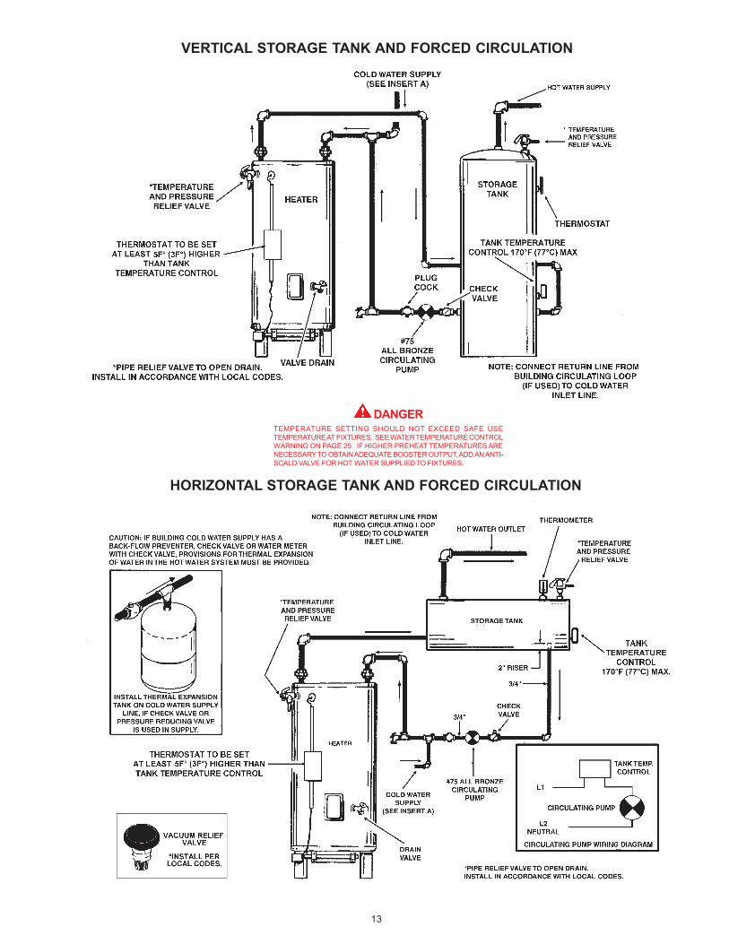
VERTICAL STORAGE TANK AND FORCED CIRCULATION
DANGERTEMPERATURE SETTING SHOULD NOT EXCEED SAFE USETEMPERATURE AT FIXTURES. SEE WATER TEMPERATURE CONTROLWARNING ON PAGE 25. IF HIGHER PREHEAT TEMPERATURES ARENECESSARY TO OBTAIN ADEQUATE BOOSTER OUTPUT, ADD AN ANTI-SCALD VALVE FOR HOT WATER SUPPLIED TO FIXTURES.
HORIZONTAL STORAGE TANK AND FORCED CIRCULATION

14
DANGERTEMPERATURE SETTING SHOULD NOT EXCEED SAFE USETEMPERATURE AT FIXTURES. SEE WATER TEMPERATURE CONTROLWARNING ON PAGE 25. IF HIGHER PREHEAT TEMPERATURES ARENECESSARY TO OBTAIN ADEQUATE BOOSTER OUTPUT, ADD AN ANTI-SCALD VALVE FOR HOT WATER SUPPLIED TO FIXTURES.
TWO TEMPERATURE - ONE HEATER HIGH TEMPERATURE STORAGEWITH RECIRCULATION OF SANITIZING LOOP
NOTE 1: TOGGLE SWITCH CONTROLS 180°F (82°C) WATERCIRCULATION. INSTALL ON OR CLOSE TO DISHWASHINGMACHINE. TOGGLE SWITCH MUST BE CLOSED (ON) DURINGTHE RINSE OPERATION AND OPEN (OFF) WHEN DISHWASHERIS NOT OPERATING OR WHEN ON LONG STANDBY.
NOTE 2: INSTALL LINE TEMPERATURE CONTROL IN AN UNINSULATEDTEE BEYOND THE DISHWASHING MACHINE TAKEOFF IN THESANITIZING LOOP. CONTROL SHOULD BE SET AT 185°F(85°C).
NOTE 3: ADJUST PLUG COCK SO THE SANITIZING LOOP FLOW RATEDOES NOT CAUSE UNNECESSARY TURBULENCE IN THE TANK.
* TEMPERED WATER LOOP, IF USED, CONNECT TO POINT “A”.**PIPE RELIEF VALVE TO OPEN DRAIN. INSTALL IN ACCORDANCE WITH LOCAL CODES.
CAUTION: IF BUILDING COLD WATER SUPPLY HAS A BACKFLOWPREVENTER, CHECK VALVE OR WATER METER WITH CHECKVALVE. PROVISIONS FOR THERMAL EXPANSION OF WATERIN THE HOT WATER SYSTEM MUST BE PROVIDED.
15
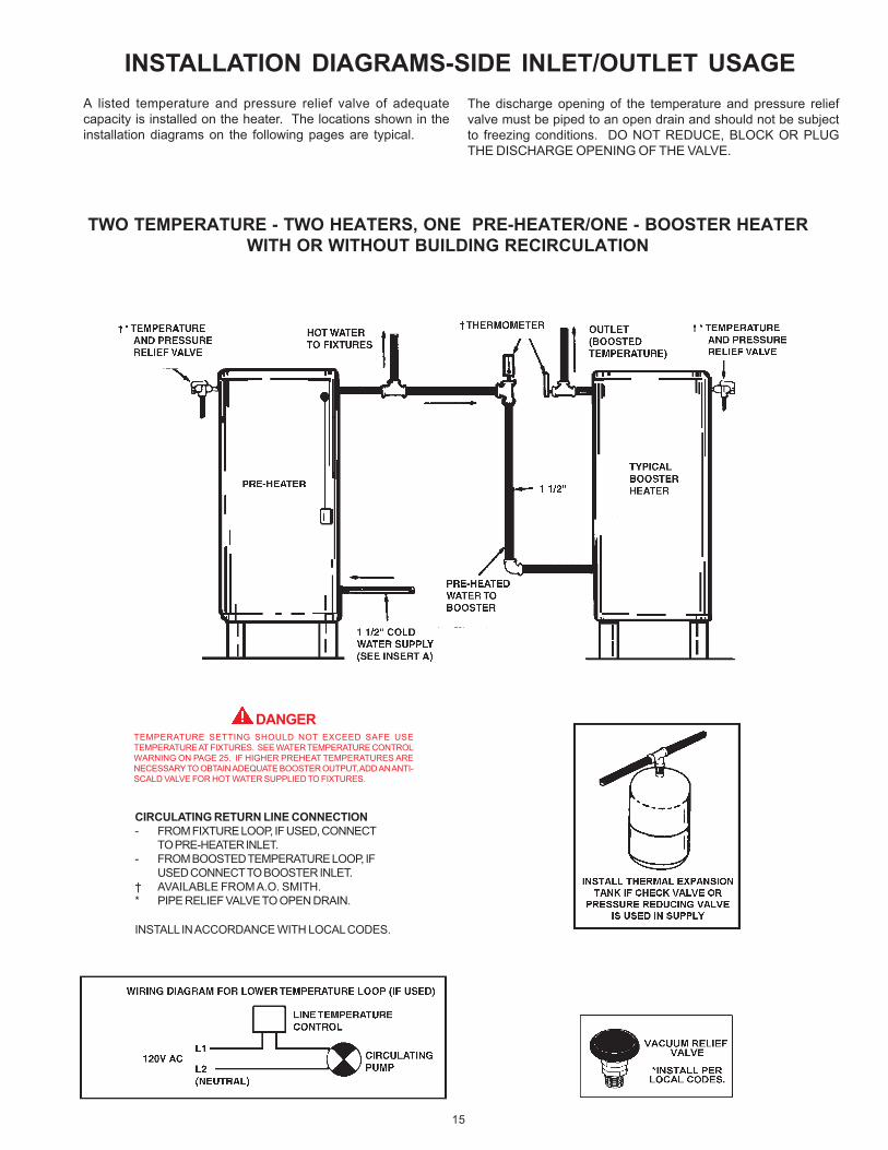
INSTALLATION DIAGRAMS-SIDE INLET/OUTLET USAGE
DANGERTEMPERATURE SETTING SHOULD NOT EXCEED SAFE USETEMPERATURE AT FIXTURES. SEE WATER TEMPERATURE CONTROLWARNING ON PAGE 25. IF HIGHER PREHEAT TEMPERATURES ARENECESSARY TO OBTAIN ADEQUATE BOOSTER OUTPUT, ADD AN ANTI-SCALD VALVE FOR HOT WATER SUPPLIED TO FIXTURES.
A listed temperature and pressure relief valve of adequatecapacity is installed on the heater. The locations shown in theinstallation diagrams on the following pages are typical.
TWO TEMPERATURE - TWO HEATERS, ONE PRE-HEATER/ONE - BOOSTER HEATERWITH OR WITHOUT BUILDING RECIRCULATION
The discharge opening of the temperature and pressure reliefvalve must be piped to an open drain and should not be subjectto freezing conditions. DO NOT REDUCE, BLOCK OR PLUGTHE DISCHARGE OPENING OF THE VALVE.
CIRCULATING RETURN LINE CONNECTION- FROM FIXTURE LOOP, IF USED, CONNECT
TO PRE-HEATER INLET.- FROM BOOSTED TEMPERATURE LOOP, IF
USED CONNECT TO BOOSTER INLET.† AVAILABLE FROM A.O. SMITH.* PIPE RELIEF VALVE TO OPEN DRAIN.
INSTALL IN ACCORDANCE WITH LOCAL CODES.

16
ONE OR TWO TEMPERATURE - ONE HEATERS,HIGH TEMPERATURESTORAGE WITH OR WITHOUT RECIRCULATION
HEATER WITH OR WITHOUT MIXING VALVE
HEATER WITH MIXING VALVE AND RECIRCULATED SANITIZING LOOPNOTE 1: TOGGLE SWITCH CONTROLS 180°F (82°C)
WATER CIRCULATION. INSTALL ON OR CLOSETO DISHWASHING MACHINE. TOGGLE SWITCHMUST BE CLOSED (ON) DURING THE RINSEOPERATION AND OPEN (OFF) WHENDISHWASHER IS NOT OPERATING OR WHENON LONG STANDBY.
NOTE 2: INSTALL LINE TEMPERATURE CONTROLIN AN UNINSULATED TEE BEYOND THEDISHWASHING MACHINE TAKEOFF INTHE SANITIZING LOOP. CONTROLSHOULD BE SET AT 185°F (85°C).
NOTE 3: ADJUST PLUG COCK SO THE SANITIZINGLOOP FLOW RATE DOES NOT CAUSE
UNNECESSARY TURBULENCE IN THE TANK.
* PIPE RELIEF VALVE TO OPEN DRAIN.
INSTALL IN ACCORDANCE WITH LOCALCODES.
CIRCULATING RETURN LINE CONNECTIONS.
- TEMPERED WATER LOOP, IF USED, CONNECT TO POINT “R”.
- STORED TEMPERATURE WATER LOOP, IF USED, CONNECT TO COLD WATER INLET.
DANGERTEMPERATURE SETTING SHOULD NOTEXCEED SAFE USE TEMPERATURE ATFIXTURES. SEE WATER TEMPERATURECONTROL WARNING ON PAGE 25. IF HIGHERPREHEAT TEMPERATURES ARE NECESSARYTO OBTAIN ADEQUATE BOOSTER OUTPUT,ADD AN ANTI-SCALD VALVE FOR HOT WATERSUPPLIED TO FIXTURES.
CAUTION: IF BUILDING COLD WATER SUPPLY HAS A BACKFLOWPREVENTER, CHECK VALVE OR WATER METER WITH CHECK VALVE.PROVISIONS FOR THERMAL EXPANSION OF WATER IN THE HOT WATERSYSTEM MUST BE PROVIDED.

17
TWO TEMPERATURE - TWO PRE-HEATERS WITH MIXING VALVE OR BOOSTERHEATER WITH OR WITHOUT BUILING RECIRCULATION
TWO PRE-HEATERS WITH MIXING VALVE
TWO PRE-HEATERS WITH BOOSTER HEATER
DANGERTEMPERATURE SETTING SHOULD NOTEXCEED SAFE USE TEMPERATURE ATFIXTURES. SEE WATER TEMPERATURECONTROL WARNING ON PAGE 25. IF HIGHERPREHEAT TEMPERATURES ARE NECESSARYTO OBTAIN ADEQUATE BOOSTER OUTPUT,ADD AN ANTI-SCALD VALVE FOR HOT WATERSUPPLIED TO FIXTURES.

18
MEDIUM TEMPERATURE - ONE HEATER WITH AUXILIARY STORAGE TANK FORCEDCIRCULATION WITH OR WITHOUT BUILDING RECIRCULATION
VERTICAL STORAGE TANK
HORIZONTAL STORAGE TANK
DANGERTEMPERATURE SETTING SHOULD NOT EXCEED SAFEUSE TEMPERATURE AT FIXTURES. SEE WATERTEMPERATURE CONTROL WARNING ON PAGE 25. IFHIGHER PREHEAT TEMPERATURES ARE NECESSARY TOOBTAIN ADEQUATE BOOSTER OUTPUT, ADD AN ANTI-SCALD VALVE FOR HOT WATER SUPPLIED TO FIXTURES.
* PIPE RELIEF VALVE TO OPEN DRAIN.
**WHEN USING AN A.O. SMITH T-140, -200, -350 OR -400 STORAGE TANK, USE LOWER 3/4” OPENING FOR TANK TEMPERATURE CONTROL.
IF BUILDING CIRCULATING LOOP IS USED,CONNECT TO AN OPENING NEAR THEBOTTOM OF THE TANK.
CAUTION: IF BUILDING COLD WATER SUPPLY HAS ABACKFLOW PREVENTER, CHECK VALVE OR WATERMETER WITH CHECK VALVE. PROVISIONS FORTHERMAL EXPANSION OF WATER IN THE HOT WATERSYSTEM MUST BE PROVIDED.
*PIPE RELIEF VALVE TO OPEN DRAIN INSTALL IN ACCORDANCE WITH LOCAL CODES.

19
MODEL DIMENSION “A”BTN-120 63”BTN-154 68”BTN-180 72”BTN-199 72”BTN-200/A 72”BTN-250/A 72”BTN-275/A 72”BTN-310/A 73”BTN-366/A 73”BTN-400/A 73”
MANIFOLD KITSTWO UNIT MANIFOLD KIT
(PART NO. 78692)
THREE UNIT MANIFOLD KIT(PART NO. 78593)
FOUR UNIT MANIFOLD KIT(PART NO. 78694)
20
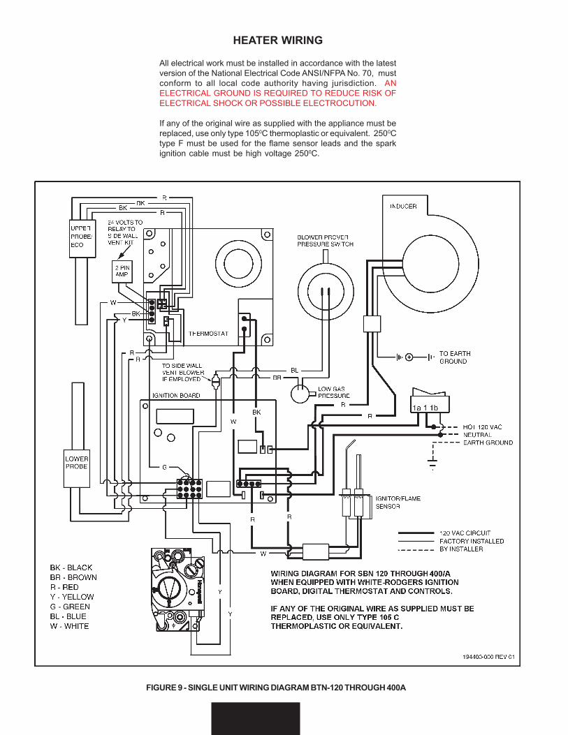
HEATER WIRING
All electrical work must be installed in accordance with the latestversion of the National Electrical Code ANSI/NFPA No. 70, mustconform to all local code authority having jurisdiction. ANELECTRICAL GROUND IS REQUIRED TO REDUCE RISK OFELECTRICAL SHOCK OR POSSIBLE ELECTROCUTION.
If any of the original wire as supplied with the appliance must bereplaced, use only type 1050C thermoplastic or equivalent. 2500Ctype F must be used for the flame sensor leads and the sparkignition cable must be high voltage 2500C.
FIGURE 9 - SINGLE UNIT WIRING DIAGRAM BTN-120 THROUGH 400A

21
GAS PIPINGContact your local gas service company to ensure that adequategas service is available and to review applicable installationcodes for your area.
Size the main gas line in accordance with Table 3. The figuresshown are for straight lengths of pipe at 0.5 in. W.C. pressuredrop, which is considered normal for low pressure systems.Note: Fittings such as elbows, tees and line regulators will addto the pipe pressure drop. Also refer to the latest version of theNational Fuel Gas Code.
WARNINGTHE HEATER IS NOT INTENDED FOR OPERATION AT HIGHERTHAN 14.0" W.C.- NATURAL GAS, (1/2 POUND PER SQUAREINCH GAGE) SUPPLY GAS PRESSURE. EXPOSURE TO HIGHERSUPPLY PRESSURE MAY CAUSE DAMAGE TO THE GAS VALVEWHICH COULD RESULT IN FIRE OR EXPLOSION. IFOVERPRESSURE HAS OCCURRED SUCH AS THROUGHIMPROPER TESTING OF GAS LINES OR EMERGENCYMALFUNCTION OF THE SUPPLY SYSTEM, THE GAS VALVEMUST BE CHECKED FOR SAFE OPERATION. MAKE SURETHAT THE OUTSIDE VENTS ON THE SUPPLY REGULATORSAND THE SAFETY VENT VALVES ARE PROTECTED AGAINSTBLOCKAGE. THESE ARE PARTS OF THE GAS SUPPLY SYSTEM,NOT THE HEATER. VENT BLOCKAGE MAY OCCUR DURINGICE STORMS.
TABLE 7 - GAS SUPPLY LINE SIZES (IN INCHES)*MAXIMUM CAPACITY OF PIPE IN
CUBIC FEET PER HOUR
LENGTH NOMINAL IRON PIPE SIZES (INCHES)IN
FEET 1/2" 3/4" 1" 1 1/4" 1 1/2" 2" 2 1/2" 3" 4"10 175 360 680 1400 2100 3960 6300 11000 2300020 120 250 465 950 1460 2750 4360 7700 1580030 97 200 375 770 1180 2200 3520 6250 1280040 82 170 320 660 990 1900 3000 5300 1090050 73 151 285 580 900 1680 2650 4750 970060 66 138 260 530 810 1520 2400 4300 880070 61 125 240 490 750 1400 2250 3900 810080 57 118 220 460 690 1300 2050 3700 750090 53 110 205 430 650 1220 1950 3450 7200100 50 103 195 400 620 1150 1850 3250 6700125 44 93 175 360 550 1020 1650 2950 6000150 40 84 160 325 500 950 1500 2650 5500175 37 77 145 300 460 850 1370 2450 5000200 35 72 135 280 430 800 1280 2280 4600
IT IS IMPORTANT TO GUARD AGAINST GAS VALVE FOULINGFROM CONTAMINANTS IN THE GAS WAYS. SUCH FOULINGMAY CAUSE IMPROPER OPERATION, FIRE OR EXPLOSION.
IF COPPER SUPPLY LINES ARE USED THEY MUST BEINTERNALLY TINNED AND CERTIFIED FOR GAS SERVICE.BEFORE ATTACHING THE GAS LINE, BE SURE THAT ALL GASPIPE IS CLEAN ON THE INSIDE.
TO TRAP ANY DIRT OR FOREIGN MATERIAL IN THE GASSUPPLY LINE, A DIRT LEG (SOMETIMES CALLED SEDIMENTTRAP OR DRIP LEG) MUST BE INCORPORATED IN THE PIPING(SEE FIG. 10). THE DIRT LEG MUST BE READILY ACCESSIBLEAND NOT SUBJECT TO FREEZING CONDITIONS. INSTALL INACCORDANCE WITH RECOMMENDATIONS OF SERVING GASSUPPLIERS. REFER TO THE LATEST VERSION OF THENATIONAL FUEL GAS CODE.
To prevent damage, care must be taken not to apply too muchtorque when attaching gas supply pipe to gas valve inlet.
Apply joint compounds (pipe dope) sparingly and only to themale threads of pipe joints. Do not apply compounds to the firsttwo threads. Use compounds resistant to the action of liquefiedpetroleum gases.
BEFORE PLACING THE HEATER IN OPERATION, CHECK FORGAS LEAKAGE. Use soap and water solution or other materialacceptable for the purpose in locating the leaks. DO NOT USEMATCHES, CANDLES, FLAME OR OTHER SOURCES OFIGNITION FOR THIS PURPOSE.
DISCONNECT THE HEATER AND ITS MANUAL GAS SHUTOFFVALVE FROM THE GAS SUPPLY PIPING SYSTEM DURING ANYSUPPLY PRESSURE TESTING EXCEEDING 1/2 PSIG. GASSUPPLY LINE MUST BE CAPPED WHEN DISCONNECTEDFROM THE HEATER FOR TEST PRESSURES OF 1/2 PSIG ORLESS. THE APPLIANCE NEED NOT BE DISCONNECTED, BUTMUST BE ISOLATED FROM THE SUPPLY PRESSURE TEST BYCLOSING THE MANUAL GAS SHUTOFF VALVE.
GAS PIPING AND DIRT LEG INSTALLATION
FIGURE 10
PURGING
Gas line purging is required with new piping or systems in whichair has entered.
CAUTIONPURGING SHOULD BE PERFORMED BY PERSONSEXPERIENCED IN THIS TYPE GAS SERVICE. TO AVOID RISKOF FIRE OR EXPLOSION, PURGE DISCHARGE MUST NOTENTER CONFINED AREAS OR SPACES WHERE IGNITION CANOCCUR. THE AREA MUST BE WELL VENTILATED AND ALLSOURCES OF IGNITION MUST BE INACTIVATED OR REMOVED.
GAS METER SIZE — NATURAL GASES ONLY
Be sure the gas meter has sufficient capacity to supply the fullrated gas input of the water heater as well as the requirementsof all other gas fired equipment supplied by the meter. If gasmeter is too small, ask the gas company to install a larger meterhaving adequate capacity.
GAS PRESSURE REGULATOR
The gas pressure regulator is built into the gas valve and isequipped to operate on the gas specified on model and ratingplate. The regulator is factory adjusted to deliver gas to burner at

22
correct water column pressure allowing for a nominal pressuredrop through the controls.
The minimum gas supply pressure for input adjustment mustnot be less than 4.5" w.c. (1.12 kPa) for natural gas.
Do not subject the combination gas valve to inlet gaspressures of more than 14.0" W.C. (3.48 kPa) - natural gas.A service regulator is necessary if higher gas pressures areencountered.
Gas pressure specified in Table 4, refer to flow pressure takenat pressure tap of automatic gas valve while heater is operating.
TABLE 8MANIFOLD GAS PRESSURE IN INCHESOF WATER COLUMN (ALL MODELS*)
TYPE OF GASNatural
3.5 (0.87 kPa)
TABLE 9APPROXIMATE TIME REQUIRED TO CONSUME
1 CU. FT. OF GAS AT FULL CAPACITY
TIME REQ’DINPUT TYPE BTUH TO CONSUMERATE OF PER 1 CU. FT.
(BTUH) GAS CU. FT. OF GAS120,000 NATURAL 1050 31.5 SEC.154,000 NATURAL 1050 24.5 SEC.180,000 NATURAL 1050 21.1 SEC.199,000 NATURAL 1050 19.0 SEC.190,000 NATURAL 1050 20.1 SEC.250,000 NATURAL 1050 15.1 SEC.275,000 NATURAL 1050 13.75 SEC.310,000 NATURAL 1050 12.4 SEC.366,000 NATURAL 1050 10.4 SEC.390,000 NATURAL 1050 9.5 SEC.
Figures shown are valid for 0-2000 ft. installations. See “HIGHALTITUDE INSTALLATIONS” for deration requirements over 2000ft.
OPERATIONIMPORTANT
A qualified person must perform the initial firing of the heater. Atthis time the user should not hesitate to ask the individual anyquestions which they may have in regard to the operation andmaintenance of the unit.
An Operational Checklist is included at the rear of this manual.By using this checklist the user may be able to make minoroperational adjustments and avoid unnecessary service calls.However, the user should not attempt repairs which are not listedunder the USER column.
GENERAL
NEVER OPERATE THE HEATER WITHOUT FIRST BEINGCERTAIN IT IS FILLED WITH WATER AND A TEMPERATURE
AND PRESSURE RELIEF VALVE IS INSTALLED IN THE RELIEFVALVE OPENING OF THE HEATER.
SHOULD OVERHEATING OCCUR OR THE GAS SUPPLY FAILTO SHUT OFF, TURN OFF THE MANUAL GAS CONTROL VALVETO THE APPLIANCE.
CAUTIONBefore proceeding with the operation of the unit make sure thewater heater and system are filled with water and all air isexpelled.
FILLING
1. Close the heater drain valve by turning handle clockwise.
2. Open a nearby hot water faucet to permit the air in the systemto escape.
3. Fully open the cold water inlet pipe valve allowing the heaterand piping to be filled.
4. Close the hot water faucet as water starts to flow.
5. The heater is ready to be operated.
WARNINGTHE GAS VALVE MUST HAVE BEEN IN THE OFF POSITION FORAT LEAST 5 MINUTES. This waiting period is an important safetystep. Its purpose is to permit gas that may have accumulated inthe combustion chamber to clear. IF YOU DETECT GAS ODORAT THE END OF THIS PERIOD DO NOT PROCEED WITHLIGHTING. RECOGNIZE THAT GAS EVEN IF IT SEEMS WEAK,MAY INDICATE PRESENCE OF ACCUMULATED GASSOMEPLACE IN THE AREA WITH RISK OF FIRE OREXPLOSION. SEE THE FRONT PAGE FOR STEPS TO BE TAKEN.
All gas and water lines leak tested and open.
Read SEQUENCE OF OPERATION section of this manual priorto lighting and operating this appliance.
With above conditions satisfied, start the unit in accordance withthe instructions on the operating label attached to the heater.For your convenience a copy of the instructions are shown ofpage 24. Each heater is equipped with an ignition control board.The controller will try three times to light the main burner beforegoing into lockout. After the controller tries three times, it willwait one hour before trying to light the unit again. This cycle willcontinue until the main burners are ignited or the unit is shutdown.
ADJUSTMENTS
ON INITIAL STARTUP SOME ADJUSTMENTS ARE NECESSARY.
1. CHECK MANIFOLD AND INLET GAS PRESSURES.
2. CYCLE CHECK - CHECK AT LEAST ONE BURNEROPERATION - WHEN THERMOSTAT IS SATISFIED, BURNERWILL SHUT OFF AND INDUCER WILL STOP RUNNING. ONCALL FOR HEAT - THE INDUCER WILL COME ON ANDCLOSE THE PRESSURE SWITCH AND THE IGNITIONSEQUENCE DESCRIBED ABOVE WILL BEGIN, SEE“SEQUENCE OF OPERATION”.

23
SEQUENCE OF OPERATIONThe following information will describe the Sequence ofOperation for this appliance.
1. Switch power on to unit.
2. Thermostat calls for heat.
3. Ignition Control Board performs diagnostic check on systemcomponents.
4. On completion of diagnostics check, the Ignition ControlBoard sends signal to Exhaust Inducer.
5. Exhaust Inducer begins drawing air through appliance closingthe Prover Switch.
6. On completion of Prover Switch engagement, the IgnitionControl Board begins the ignition cycle.
7. The Ignition Control Board provides power to the Silicon NitrideIgnitor.
8. The Silicon Nitride Ignitor heats up for approximately 17 to 20seconds.
9. At the end of Silicon Nitride Ignitor’s warm-up, the IgnitionControl Board opens the Gas Valve.
10.From the time the Gas Valve opens, the Ignition Control Boardwaits 3 seconds and then shuts off power to the Silicon NitrideIgnitor.
11.From the time the Silicon Nitride Ignitor’s power is shut off,the Ignition Control Board waits 3 more seconds to monitorthe Flame Sensor.
12.If the Flame Sensor does not detect a strong enough flame,the Ignition Control Board shuts off the Gas Valve and allowsthe Exhaust Inducer to purge the unit for 20 seconds. At thattime, the Ignition Control Board restarts with step 7. It will tryand ignite the main burners 2 more times. If the unit does notlight, the Ignition Control Board will wait one hour and thenrestart at step 3. This cycle will continue until the unit lights orthe power is shutoff to the unit.
13.If the Flame Sensor detects a strong flame, the Ignition ControlBoard will allow the unit to operate until the thermostat issatisfied.
14.Once the unit is satisfied, the Ignition Control Board will shutoff the Gas Valve and the unit will be in standby mode untilanother call for heat is initiated by the thermostat.
See the flow chart on page 31 for more information.
24
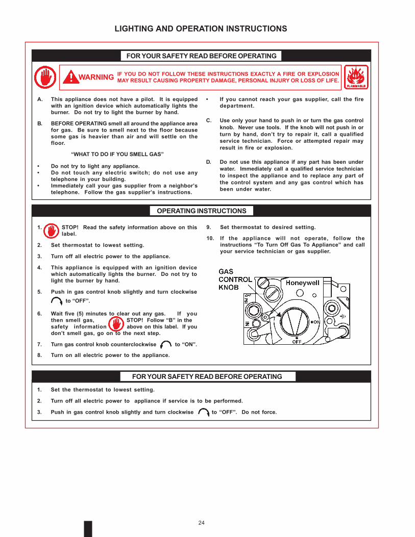
A. This appliance does not have a pilot. It is equippedwith an ignition device which automatically lights theburner. Do not try to light the burner by hand.
B. BEFORE OPERATING smell all around the appliance areafor gas. Be sure to smell next to the floor becausesome gas is heavier than air and will settle on thefloor.
“WHAT TO DO IF YOU SMELL GAS”
• Do not try to light any appliance.• Do not touch any electric switch; do not use any
telephone in your building.• Immediately call your gas supplier from a neighbor’s
telephone. Follow the gas supplier’s instructions.
IF YOU DO NOT FOLLOW THESE INSTRUCTIONS EXACTLY A FIRE OR EXPLOSIONMAY RESULT CAUSING PROPERTY DAMAGE, PERSONAL INJURY OR LOSS OF LIFE.
1. STOP! Read the safety information above on thislabel.
2. Set thermostat to lowest setting.
3. Turn off all electric power to the appliance.
4. This appliance is equipped with an ignition devicewhich automatically lights the burner. Do not try tolight the burner by hand.
5. Push in gas control knob slightly and turn clockwise to “OFF”.
6. Wait five (5) minutes to clear out any gas. If youthen smell gas, STOP! Follow “B” in thesafety information above on this label. If youdon’t smell gas, go on to the next step.
7. Turn gas control knob counterclockwise to “ON”.
8. Turn on all electric power to the appliance.
FOR YOUR SAFETY READ BEFORE OPERATING
OPERATING INSTRUCTIONS
WARNING
• If you cannot reach your gas supplier, call the firedepartment.
C. Use only your hand to push in or turn the gas controlknob. Never use tools. If the knob will not push in orturn by hand, don’t try to repair it, call a qualifiedservice technician. Force or attempted repair mayresult in fire or explosion.
D. Do not use this appliance if any part has been underwater. Immediately call a qualified service technicianto inspect the appliance and to replace any part ofthe control system and any gas control which hasbeen under water.
1. Set the thermostat to lowest setting.
2. Turn off all electric power to appliance if service is to be performed.
3. Push in gas control knob slightly and turn clockwise to “OFF”. Do not force.
FOR YOUR SAFETY READ BEFORE OPERATING
9. Set thermostat to desired setting.
10. If the appliance will not operate, follow theinstructions “To Turn Off Gas To Appliance” and callyour service technician or gas supplier.
LIGHTING AND OPERATION INSTRUCTIONS

25
WATER TEMPERATURE CONTROL
DANGERTHIS WATER HEATER IS EQUIPPED WITH AN ADJUSTABLETHERMOSTAT TO CONTROL WATER TEMPERATURE. HOTWATER TEMPERATURES REQUIRED FOR AUTOMATICDISHWASHER AND LAUNDRY USE CAN CAUSE SCALDBURNS RESULTING IN SERIOUS PERSONAL INJURY AND/OR DEATH. THE TEMPERATURE AT WHICH INJURY OCCURSVARIES WITH THE PERSON'S AGE AND TIME OF EXPOSURE.THE SLOWER RESPONSE TIME OF CHILDREN, AGED ORDISABLED PERSONS INCREASES THE HAZARDS TO THEM.NEVER ALLOW SMALL CHILDREN TO USE A HOT WATER TAP,OR TO DRAW THEIR OWN BATH WATER. NEVER LEAVE ACHILD OR DISABLED PERSON UNATTENDED IN A BATHTUBOR SHOWER.
THE WATER HEATER SHOULD BE LOCATED IN AN AREAWHERE THE GENERAL PUBLIC DOES NOT HAVE ACCESS TOSET TEMPERATURES.
SETTING THE WATER HEATER TEMPERATURE AT 120°F (49°C)WILL REDUCE THE RISK OF SCALDS. Some states or provincesrequire settings at specific lower temperatures.
Below you will find listed the approximate time-to-burnrelationship for normal adult skin. Short repeated heating cyclescaused by small hot water uses can cause temperatures at thepoint of use to exceed the thermostat setting by up to 20F°. If youexperience this type of use, you should consider using lowertemperature settings to reduce scald hazards.
Temperature Time to Produce 2nd & 3rdSetting Degree Burns on Adult Skin180°F (82°C) Nearly instantaneous170°F (77°C) Nearly instantaneous160°F (71°C) About 1/2 second150°F (66°C) About 1-1/2 seconds140°F (60°C) Less than 5 seconds130°F (54°C) About 30 seconds120°F (49°C) More than 5 minutes
Valves for reducing point-of-use temperature by mixing cold andhot water are available. Also available are inexpensive devicesthat attach to faucets to limit hot water temperatures. Contact alicensed plumber or the local plumbing authority.
The water temperature is controlled by a thermostat, fig. 2, whichhas two sensing elements. One sensor is located near the topof the tank and the other is near the center. The thermostat is setin the lowest position before the heater leaves the factory.
The thermostat temperature dial, fig. 2, is accessible by removingthe control cover. The dial is adjustable and may be set for1200 (49°C) to 1800F (82°C) water temperature, but 1200F (49°C)is the recommended starting point. It is suggested the dial be
placed on the lowest setting which produces an acceptable hotwater supply. This will always give the most energy efficientoperation. The temperature control has a 4F° fixed differential.
CHECKING VENTINGThe following steps shall be followed with each applianceconnected to the venting system placed in operation, while anyother appliances connected to the venting system are not inoperation.
1. Seal any unused openings in the venting system.
2. Inspect the venting system for proper size and horizontalpitch, as required in the National Fuel Gas Code, ANSIZ223.1or the CAN/CGA B149 Installation Codes and theseinstructions. Determine that there is no blockage or restriction,leakage, corrosion and other deficiencies which could causean unsafe condition.
3. So far as is practical, close all building doors and windowsand all doors between the space in which the water heater(s)connected to the venting system are located and other spacesof the building. Turn on all appliances not connected to theventing system. Turn on all exhaust fans, such as rangehoods and bathroom exhausts, so they shall operate atmaximum speed. Close fireplace dampers.
4. Follow the lighting instruction. Place the water heater beinginspected in operation. Adjust thermostat so appliance shalloperate continuously.
5. Test for spillage at the burner level after 5 minutes of mainburner operation.
6. After it has been determined that each BTN connected to theventing system properly vents when tested as outlined above,return doors, windows, exhaust fans, fireplace dampers andany other gas burning appliance to their previous conditionsof use.
7. If improper venting is observed during any of the above tests,the venting system must be corrected.
WARNINGFAILURE TO CORRECT BACK DRAFTS MAY CAUSE AIRCONTAMINATION AND UNSAFE CONDITIONS.
• If the back draft cannot be corrected by the normal method orif a suitable draft cannot be obtained, a blower type flue gasexhauster must be employed to assure proper venting andcorrect combustion.
PREVENTIVE MAINTENANCECHECK THE IGNITOR ASSEMBLY
At least once a year, check the ignitor assembly, Fig. 11, and themain burner, Fig. 12, for proper operation. Refer to the followingignitor assembly and main burner sections.
IGNITOR ASSEMBLY
For access to ignitor assembly, unfasten two screws to burnercover and remove. Locate the burner with the ignitor assemblyand remove screw holding burner to manifold. Slide burner outto access ignitor assembly.
26
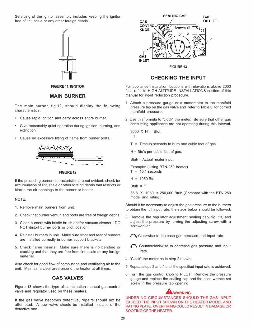
Servicing of the ignitor assembly includes keeping the ignitorfree of lint, scale or any other foreign debris.
FIGURE 11, IGNITOR
MAIN BURNER
The main burner, fig.12, should display the followingcharacteristics:
• Cause rapid ignition and carry across entire burner.
• Give reasonably quiet operation during ignition, burning, andextinction.
• Cause no excessive lifting of flame from burner ports.
FIGURE 12
If the preceding burner characteristics are not evident, check foraccumulation of lint, scale or other foreign debris that restricts orblocks the air openings to the burner or heater.
NOTE:
1. Remove main burners from unit.
2. Check that burner venturi and ports are free of foreign debris.
3. Clean burners with bristle brush and/or vacuum cleaner - DONOT distort burner ports or pilot location.
4. Reinstall burners in unit. Make sure front and rear of burnersare installed correctly in burner support brackets.
5. Check flame inserts. Make sure there is no bending orcracking and that they are free from lint, scale or any foreignmaterial.
Also check for good flow of combustion and ventilating air to theunit. Maintain a clear area around the heater at all times.
GAS VALVESFigure 13 shows the type of combination manual gas controlvalve and regulator used on these heaters.
If the gas valve becomes defective, repairs should not beattempted. A new valve should be installed in place of thedefective one.
FIGURE 13
CHECKING THE INPUTFor appliance installation locations with elevations above 2000feet, refer to HIGH ALTITUDE INSTALLATIONS section of thismanual for input reduction procedure.
1. Attach a pressure gauge or a manometer to the manifoldpressure tap on the gas valve and refer to Table 3, for correctmanifold pressure.
2. Use this formula to “clock” the meter. Be sure that other gasconsuming appliances are not operating during this interval.
3600 X H = Btuh T
T = Time in seconds to burn one cubic foot of gas.
H = Btu’s per cubic foot of gas.
Btuh = Actual heater input.
Example: (Using BTN-250 heater)T = 15.1 seconds
H = 1050 Btu
Btuh = ?
36.8 X 1050 = 250,000 Btuh (Compare with the BTN 250model and rating.)
Should it be necessary to adjust the gas pressure to the burnersto obtain the full input rate, the steps below should be followed:
3. Remove the regulator adjustment sealing cap, fig. 13, andadjust the pressure by turning the adjusting screw with ascrewdriver.
Clockwise to increase gas pressure and input rate.
Counterclockwise to decrease gas pressure and inputrate.
4. “Clock” the meter as in step 2 above.
5. Repeat steps 3 and 4 until the specified input rate is achieved.
6. Turn the gas control knob to PILOT. Remove the pressuregauge and replace the sealing cap and the allen wrench setscrew in the pressure tap opening.
WARNINGUNDER NO CIRCUMSTANCES SHOULD THE GAS INPUTEXCEED THE INPUT SHOWN ON THE HEATER MODEL ANDRATING PLATE. OVERFIRING COULD RESULT IN DAMAGE ORSOOTING OF THE HEATER.
27
When the heater is operating at full capacity, or full gas input, itshould consume 1 cu. ft. of gas in time indicated on Table 9.
VENTING SYSTEMExamine the venting system every six months for obstructionsand/or deterioration of the vent piping.
Remove all soot or other obstructions from chimney which willretard free draft.
REMOTE STORAGE TANKTEMPERATURE CONTROL
The water temperature in the remote storage tank (if used) iscontrolled by the storage tank temperature control. The sensingelement is mounted in the hot water storage tank, see page 13.
A change in water temperature in the storage tank lower than thetank temperature control setting will cause the sensor to activatethe circulating pump. The pump then circulates the water throughthe heater where the thermostat senses the drop in watertemperature and activates main burner operation of the appliance.If the storage tank temperature control is out of calibration, replacewith new control.
WARNINGSHOULD OVERHEATING OCCUR OR THE GAS SUPPLY FAILTO SHUT OFF, TURN OFF THE MANUAL GAS CONTROL VALVETO THE APPLIANCE.
RELIEF VALVEAt least once a year, the temperature and pressure relief valveshould be checked to ensure that it is in operating condition. Liftthe lever at the top of the valve several times until the valve seatsproperly and operates freely.
If the appliance installation includes other relief valves, such asin “remote” storage tanks etc., check their relief valve operationwith the same frequency.
WARNINGTHE WATER PASSING OUT OF THE VALVE DURING THISCHECKING OPERATION MAY BE EXTREMELY HOT. AVOIDCONTACT AND DISCHARGE SAFELY TO PREVENT WATERDAMAGE.
If the temperature and pressure relief valve on the heaterdischarges periodically or continuously, a problem exists. Thismay be due to unusually high water temperatures or pressuresin the system, or to a faulty relief valve. Contact your dealer or aqualified service technician to find the cause of the problem andto correct it. This may also be due to thermal expansion in aclosed water supply system. Contact the water supplier or localplumbing inspector on how to correct this situation. DO NOTPLUG THE TEMPERATURE AND PRESSURE RELIEF VALVE.
WARNINGSHOULD OVERHEATING OCCUR OR THE GAS SUPPLY FAILTO SHUT OFF, TURN OFF THE MANUAL GAS CONTROL VALVETO THE APPLIANCE.
HOT WATER ODOROn occasion, hot water may develop a strong odor. If this occursdrain the heater completely, flush thoroughly, and refill. If the
problem persists, chlorination of the heater and replacement ofthe factory installed magnesium anodes with aluminum anodesmay correct the condition.
Occasionally water softener companies recommend removal ofheater anodes for odor reasons.
CAUTIONUnauthorized removal of the anode(s) will void the warranty. Forfurther information contact your dealer.
ANODE ROD INSPECTIONThe heater tank is equipped with anode rods to provide corrosioncontrol. At least once a year the anode rods should be checkedto determine if replacement is necessary. Initially the anoderods are approximately 7/8" in diameter with a 1/8" diametersteel core wire running down the center of the anode material.THE ANODES SHOULD BE REPLACED when the 1/8" diametercore wire is visible as this means that the anode material hasbeen expended in the control of corrosion.
For models with top inlet and outlet, it is recommended that,before removing the inner cover for cleaning, inspection orremoval of inner parts, you obtain two new nipple collars, partno. 74060. The nipple collars on the heater will usually bedamaged when removed. New pipe collars will insure that theseal is such as to prevent leakage of flue products when properlyinstalled.
NOTE: Anode rod inspection may need to be made morefrequently in areas subject to acid rain that obtains their watersupply from surface water as the low pH will accelerate anodeactivity.
CAUTION: Close cold water inlet valve serving heater and opennearby hot water faucet to relieve the pressure in the heaterbefore attempting to remove anode(s) for inspection.
FLUSHING1. Turn off the heater electrical disconnect switch.
2. Open the drain valve and allow water to flow until it runs clean.
3. Close the drain valve when finished flushing.
4. Turn on the heater electrical disconnect switch.
DRAINING
The heater must be drained if it is to be shut down and exposedto freezing temperatures. Maintenance and service proceduresmay also require draining the heater.
1. Turn off the heater electrical disconnect switch.
2. Close the cold water inlet valve to heater.
3. Open a nearby hot water faucet to vent the system.
4. Open the heater drain valve.
5. If the heater is being drained for an extended shutdown, it issuggested the drain valve be left open during this period.
• Follow FILLING instructions when restoring hot water service.
28
Hydrochloric base acids are not recommended for use on glasslined tanks.
CAUTIONObserve handling instructions on label of product being used.
TANK CLEANOUT PROCEDURE
The following practices will ensure longer life and enable theunit to operate at its designed efficiency:
1. Once a month the heater should be flushed. Open the drainvalve and allow two gallons of water to drain from the heater.Inlet water valve should remain open to maintain pressure intank.
2. A cleanout opening is provided for periodic cleaning of thetank. Gas must be shut off and heater drained before openingcleanout.
To clean heater through cleanout opening, proceed as follows:
1. Drain heater.
2. Remove outer cover plate from lower side of heater jacket.
3. Remove six (6) hex head screws securing tank cleanout plateand remove plate.
4. Remove lime, scale, or sediment using care not to damagethe glass lining.
5. Inspect cleanout plate gasket, if new gasket is required,replace with A. O. Smith part no. 99038.
6. Install cleanout plate. Be sure to draw plate up tight bytightening screws securely.
7. Replace outer jacket cover plate.
In some water areas the sediment might not be removed by thismethod and may result in the water heater making rumbling orboiling noises. To dissolve and remove these more stubbornmineral deposits, A. O. Smith UN•LIME Professional Delimershould be used.
DELIMING USING FLO-JUG METHOD
UN•LIME in the 5 gallon size is recommended for deliming ofthe BT-80 100 models. UN•LIME with the necessary hoses andfittings to delime your heater is also available as a kit: Up-N-Down Transfer Kit. Contact your local A.O. Smith dealer,distributor or, A.O. Smith Water Products Company:
Telephone: (800) 433-2545Fax: (800) 433-2515Website: www.hotwater.com/parts
Prepare the Water HeaterTo delime the water heater using the Flo-Jug method, firstprepare the heater for deliming as described in the "Why? When?and How?" booklet, Form No. 4800. Then install the long plasticmale adapter fitting into the drain valve opening of the waterheater. Use teflon tape and hand tighten only. Do not overtighten.
Prepare the Up-N-Down Transfer KitThe next step is the preparation on the Up-N-Down Transfer Kit,if you have not already done so:
1. With the 5 gallon Up-N-Down container in the vertical position,unscrew the plastic vent cap in the handle and pierce theplastic membrane over the vent boss under the cap to allowthe container to vent.
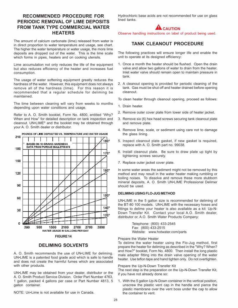
RECOMMENDED PROCEDURE FORPERIODIC REMOVAL OF LIME DEPOSITSFROM TANK TYPE COMMERCIAL WATER
HEATERSThe amount of calcium carbonate (lime) released from water isin direct proportion to water temperature and usage, see chart.The higher the water temperature or water usage, the more limedeposits are dropped out of the water. This is the lime scalewhich forms in pipes, heaters and on cooking utensils.
Lime accumulation not only reduces the life of the equipmentbut also reduces efficiency of the heater and increases fuelconsumption.
The usage of water softening equipment greatly reduces thehardness of the water. However, this equipment does not alwaysremove all of the hardness (lime). For this reason it isrecommended that a regular schedule for deliming bemaintained.
The time between cleaning will vary from weeks to monthsdepending upon water conditions and usage.
Refer to A. O. Smith booklet, Form No. 4800, entitled “Why?When and How” for detailed description on tank inspection andcleanout. UN•LIME® and the booklet may be obtained throughyour A. O. Smith dealer or distributor.
FIGURE 14
DELIMING SOLVENTSA. O. Smith recommends the use of UN•LIME for deliming.UN•LIME is a patented food grade acid which is safe to handleand does not create the harmful fumes which are associatedwith other products.
UN•LIME may be obtained from your dealer, distributor or theA. O. Smith Product Service Division. Order Part Number 4763,1 gallon, packed 4 gallons per case or Part Number 4813, 5gallon container.
NOTE: Un•Lime is not available for use in Canada.
29
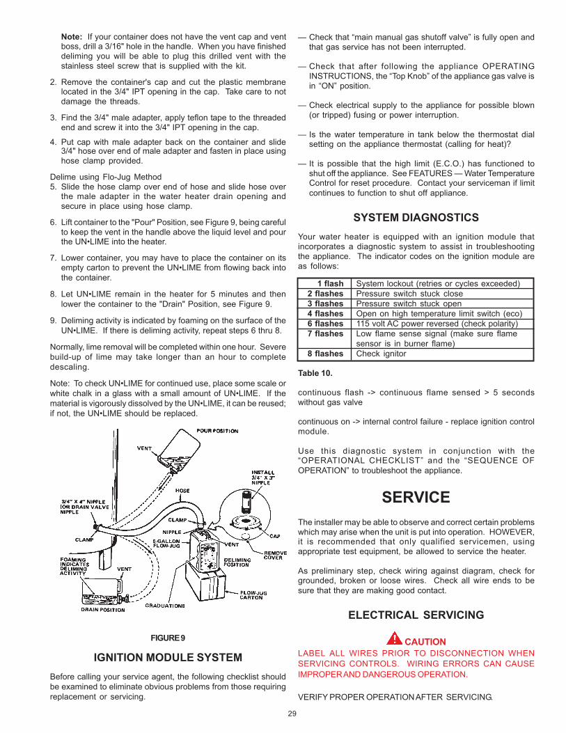
Note: If your container does not have the vent cap and ventboss, drill a 3/16" hole in the handle. When you have finisheddeliming you will be able to plug this drilled vent with thestainless steel screw that is supplied with the kit.
2. Remove the container's cap and cut the plastic membranelocated in the 3/4" IPT opening in the cap. Take care to notdamage the threads.
3. Find the 3/4" male adapter, apply teflon tape to the threadedend and screw it into the 3/4" IPT opening in the cap.
4. Put cap with male adapter back on the container and slide3/4" hose over end of male adapter and fasten in place usinghose clamp provided.
Delime using Flo-Jug Method5. Slide the hose clamp over end of hose and slide hose over
the male adapter in the water heater drain opening andsecure in place using hose clamp.
6. Lift container to the "Pour" Position, see Figure 9, being carefulto keep the vent in the handle above the liquid level and pourthe UN•LIME into the heater.
7. Lower container, you may have to place the container on itsempty carton to prevent the UN•LIME from flowing back intothe container.
8. Let UN•LIME remain in the heater for 5 minutes and thenlower the container to the "Drain" Position, see Figure 9.
9. Deliming activity is indicated by foaming on the surface of theUN•LIME. If there is deliming activity, repeat steps 6 thru 8.
Normally, lime removal will be completed within one hour. Severebuild-up of lime may take longer than an hour to completedescaling.
Note: To check UN•LIME for continued use, place some scale orwhite chalk in a glass with a small amount of UN•LIME. If thematerial is vigorously dissolved by the UN•LIME, it can be reused;if not, the UN•LIME should be replaced.
FIGURE 9
IGNITION MODULE SYSTEMBefore calling your service agent, the following checklist shouldbe examined to eliminate obvious problems from those requiringreplacement or servicing.
— Check that “main manual gas shutoff valve” is fully open andthat gas service has not been interrupted.
— Check that after following the appliance OPERATINGINSTRUCTIONS, the “Top Knob” of the appliance gas valve isin “ON” position.
— Check electrical supply to the appliance for possible blown(or tripped) fusing or power interruption.
— Is the water temperature in tank below the thermostat dialsetting on the appliance thermostat (calling for heat)?
— It is possible that the high limit (E.C.O.) has functioned toshut off the appliance. See FEATURES — Water TemperatureControl for reset procedure. Contact your serviceman if limitcontinues to function to shut off appliance.
SYSTEM DIAGNOSTICSYour water heater is equipped with an ignition module thatincorporates a diagnostic system to assist in troubleshootingthe appliance. The indicator codes on the ignition module areas follows:
1 flash System lockout (retries or cycles exceeded)2 flashes Pressure switch stuck close3 flashes Pressure switch stuck open4 flashes Open on high temperature limit switch (eco)6 flashes 115 volt AC power reversed (check polarity)7 flashes Low flame sense signal (make sure flame
sensor is in burner flame)8 flashes Check ignitor
Table 10.
continuous flash -> continuous flame sensed > 5 secondswithout gas valve
continuous on -> internal control failure - replace ignition controlmodule.
Use this diagnostic system in conjunction with the“OPERATIONAL CHECKLIST” and the “SEQUENCE OFOPERATION” to troubleshoot the appliance.
SERVICEThe installer may be able to observe and correct certain problemswhich may arise when the unit is put into operation. HOWEVER,it is recommended that only qualified servicemen, usingappropriate test equipment, be allowed to service the heater.
As preliminary step, check wiring against diagram, check forgrounded, broken or loose wires. Check all wire ends to besure that they are making good contact.
ELECTRICAL SERVICING
CAUTIONLABEL ALL WIRES PRIOR TO DISCONNECTION WHENSERVICING CONTROLS. WIRING ERRORS CAN CAUSEIMPROPER AND DANGEROUS OPERATION.
VERIFY PROPER OPERATION AFTER SERVICING.

30
REPLACEMENT PARTS, SERVICE HANDBOOKS AND TRAINING AIDS
Replacement parts may be ordered through A.O. Smith dealers, authorized servicers or distributors. Refer to the Yellow Pages forwhere to call or contact the A.O. Smith Water Products Company, Product Service Division, 5621 West 115th Street, Alsip, IL 60803,1-800- 433-2545. When ordering parts be sure to state the quantity, part number and description of the item(s) including thecomplete model and serial number as it appears on the product. Refer to the parts list for more information.
REPLACEMENT PARTS
SEQUENCE OF OPERATION FLOW CHARTDescription of this flow chart can be found in the “SEQUENCE OF OPERATION” section found on page 23.
Switch power onto unit.
Thermostat callsfor heat.
Ignition ControlBoard performs
diagnostic check oncomponents
Ignition ControlBoard sends powerto Exhaust Inducer
Exhaust Inducerengages Prover
Switch
Ignition ControlBoard providespower to SilconNitride Ignitor
Silicon NitrideIgnitor
warms up for20 seconds
IgnitionControl Board
opens GasValve.
Ignition ControlBoard shuts offSilicon Nitride
Ignitor after3 seconds
Ignition ControlBoard waits 3 more
seconds tomonitor Flame
Sensor.
Did MainBurner Light?
YES
Ignition ControlBoard monitorsunits until T’Stat
is satisfied.
Ignition ControlBoard shuts off GasValve and allows theExhaust Inducer topurge appliance for
20 seconds.
NO

31
OPERATIONAL CHECKLISTThis checklist in conjunction with “TROUBLESHOOTING” and the “SEQUENCE OF OPERATION” should be used as an on-the-jobtroubleshooting guide to identify the cause of incorrect system operation and suggest a remedy for its correction. Becauseimproper piping and wiring can result in unsatisfactory system performance, it is suggested that the installation by examinedbefore using the checklist. Be sure to refer to the correct piping and wiring diagram for the type of system that is installed.
The system should be filled with water, purged of air, valves properly set and utilities connected and ready to operate.
REMEDY
COMPLAINT CAUSE USER SERVICEMAN
*Water not hot enough. Thermostat set too low. Set thermostat dial to a highertemperature.
Thermostat out of calibration. Call serviceman Recalibrate thermostat. If thermostat cannotbe recalibrated, replace.
*Insufficient hot water Thermostat set too low. Set thermostat dial to a higher*See WATER TEMPERATURE temperature.CONTROL WARNING (onPage 5). Thermostat out of calibration. Call serviceman. Recalibrate thermostat. If thermostat cannot
be recalibrated, replace.
Main manual gas shutoff Open main manual gas shutoffvalve partially closed. valve to fullest extent.
Heater too small for demand. Space usage to give heater timeto restore water temperature.
Thermostat differential is Call serviceman. Replace dual bulb controller if differential istoo wide. greater than 4°F.
Heater recovery is slower. Call serviceman. Check gas input. If incorrect, adjust gaspressure or replace main burner orifice.
Drafthood not installed or Call serviceman. Install drafthood or baffles as furnishedone or more flue baffles. with unit.
Water temperature too hot. Thermostat set too high. Set thermostat to a lower setting.
Heater makes sounds: sizzling. Condensation on outsideof tank, normal.
Rumbling. Sediment accumulation on Drain a quantity of water through Delime heater.bottom of tank. drain valve. If rumbling persists,
call a serviceman.
Ticking or metallic sounds. Expansion and contraction-normal.
Pounding. Air chambers in piping have Drain piping system and refill.become waterlogged. Heater must be off while this is
being done.
Combustion noises. Too much primary air. Adjust shutters.
Overfired heater; Incorrect Call serviceman. Check and correct as necessary.burners or orifice for typeof gas used.
Water leaks. Drain valve not closed If drain valve cannot be closedtightly. tightly, replace.
If leakage source cannot Shut off gas supply to heater Repair or in case of suspected tank leakage,be corrected or identified, and close cold water inlet valve be certain to confirm before replacing heater.call serviceman. to heater.
Gas odors. Heater is overfired. Shut off gas supply to heater Check for sooted flue passage.and call a serviceman.
Check for obstructed vent line.
Check backdraft or lack of draft.
Possible gas leaks. Shut off gas supply to heaterand call gas company at once.

32
Model BTN Limited WarrantyA. O. Smith Corporation, the warrantor, extends the following LIMITED WARRANTY to the owner of this water heater.
1. THE TANKIf the glass-lined tank in this water heater shall prove upon examination by the warrantor to have leaked due to natural corrosion from potablewater therein, during the first THREE years after initial installation, the warrantor will supply a complete new A. O. Smith water heater ofequivalent size and current model. Some government agencies are requiring energy efficient standards for water heaters. In the eventregulations prohibit sale of a model of equivalent size and construction, A. O. Smith will provide a model which complies with the regulations ofyour area, in which case the consumer will be charged the difference in price between the like replacement and the energy efficient modelrequired. The warranty on the replacement water heater will be limited to the unexpired term of the original warranty.
2. ALL OTHER PARTSIf within ONE year after initial installation of this water heater, any part or portion shall prove upon examination by the warrantor to be defectivein material or workmanship, the warrantor will repair or replace such part or portion at its option.
3. CONDITIONS AND EXCEPTIONSThis warranty shall apply only when the water heater is installed in accordance with local plumbing and building codes, ordinances andregulations, the printed instructions provided with it and good industry practices. In addition, a temperature and pressure relief valve, certifiedby A.G.A./CGA and approved by the American Society of Mechanical Engineers, must have been installed.a. This warranty shall apply only when the heater is:
(1) used at temperatures not exceeding the maximum calibrated setting of its thermostat;(2) used at water pressure not exceeding the working pressure shown on the heater;(3) filled with potable water, free to circulate at all times and with the tank free of damaging water sediment or scale deposits;(4) used in a non-corrosive and non-contaminated atmosphere;(5) used with factory approved anode(s) installed;(6) in its original installation location;(7) in the United States, its territories or possessions, and Canada;(8) sized in accordance with proper sizing techniques for commercial and/or residential water heaters;(9) bearing a rating plate which has not been altered, defaced or removed, except as required by the warrantor;(10) operated with properly installed dirt leg;(11) fired with the fuel for which it was factory built;(12) fired at the factory rated input;(13) operated with the inner and outer combustion chamber doors in place.
b. Any accident to the water heater, any misuse, abuse (including freezing) or alteration of it, any operation of it in a modified form, any use ofinsulation blankets, or any attempt to repair tank leaks will void this warranty.
c. This warranty is void if a device acting as a backflow prevention device (check valves etc.) is installed in the cold water supply the heateris connected to, unless an effective method of controlling thermal expansion is also installed at the heater(s) and operational at all times. Therelief valve installed on the heater is not an acceptable method.
4. SERVICE AND REPAIR EXPENSESUnder the limited warranty the warrantor will provide only a replacement water heater or part thereof. The owner is responsible for all othercosts. Such costs may include but are not limited to:a. Labor charges for service removal, repair or reinstallation of the water heater or any component part;b. Shipping, delivery, handling, and administrative charges for forwarding the new heater or replacement part from the nearest distributor and
returning the claimed defective heater or part to such distributor.c. All cost necessary or incidental for any material and/or permits required for installation of the replacement heater or part.
5. LIMITATIONS ON IMPLIED WARRANTIESImplied warranties, including the warranty of merchantability imposed on the sale of this heater under state law are limited to one (1) yearduration for the heater or any of its parts. Some states do not allow limitation on how long an implied warranty lasts, so the above limitation maynot apply to you.
6. CLAIM PROCEDUREAny claim under the warranty should be initiated with the dealer who sold the heater, or with any other dealer handling the warrantor’s products.If this is not practicable, the owner should contact:
A. O. Smith Water Products Company5621 West 115th StreetAlsip, IL 60803Telephone: 1-800-323-2636
a. The warrantor will only honor replacement with identical or similar water heater or parts thereof which are manufactured or distributed bythe warrantor.
b. Dealer replacements are made subject to in-warranty validation by warrantor.
7. DISCLAIMERSNO OTHER EXPRESS WARRANTY HAS BEEN OR WILL BE MADE IN BEHALF OF THE WARRANTOR WITH RESPECT TO THE MERCHANTABILITYOF THE HEATER OR THE INSTALLATION, OPERATION, REPAIR OR REPLACEMENT OF THE HEATER. THE WARRANTOR SHALL NOT BERESPONSIBLE FOR WATER DAMAGE, LOSS OF USE OF THE UNIT, INCONVENIENCE, LOSS OR DAMAGE TO PERSONAL PROPERTY OR OTHERCONSEQUENTIAL DAMAGE. THE WARRANTOR SHALL NOT BE LIABLE BY VIRTUE OF THIS WARRANTY OR OTHERWISE FOR DAMAGE TOANY PERSONS OR PROPERTY, WHETHER DIRECT OR INDIRECT, AND WHETHER ARISING IN CONTRACT OR IN TORT.a. Some states do not allow the exclusion or limitation of the incidental or consequential damage, so the above limitations or exclusions may not
apply to you.b. This warranty gives you specific legal rights, and you may also have other rights which vary from state to state.
Fill in the following for your own reference. Keep it. Registration is not a condition of warranty. The model and serial number are found on theheater’s rating plate.
Model No.___________________________ Serial No._______________________________________ Date Installed______________________
Dealer’s Name________________________________________________________________________________________________________
Dealer’s Address _______________________________________________________________ Phone No.___________________________
City and State___________________________________________________________Zip Code______________________________________
KEEP THIS WARRANTY POSTED ADJACENT TO THE HEATER FOR FUTURE REFERENCE