Detectors 1. Accelerators 2. Particle detectors overview 3. Tracking detectors.
Models 454 & 454-12 Ultrasonic Detectors (A)library.ademconet.com/MWT/fs2/1/4693.pdf ·...
12
GENERAL INFOfWATlON *The Nos. 454 and 454-12 Ultrasonic Motion Detectors emit invi.sibIe and inaudible sound waves which detect the presence of a moving object .(such as an intruder). Each unit contains two receiver transducers and two transmitter transducers which may be independently aimed straight ahead or up to 90° to the side of straight ahead. The units mount flat against a wall (or cei.Iing) without any need for brackets. Each.of the two pairs of transmitter and receiver transducers in the No. 454 can provide indoor protection for an area up to approximately 30 feet long and 14 feet wide. Additional No. 454’s can be used in larger areas without inter- fering with each other. The pattern of sound waves emitted by these units is set up by reflecting off of wal Is, ceiling, floor, furniture and other stationary objects in the area. Any movement of objects or persons in the area causes some waves to be reflected at a changed frequency (known as the Doppler effect). When the frequency of the rece ived waves changes, the shift is detected by the electronic circuitry in the unit and an alarm signal is initiated via a relay wired into the protective cir- cui t of the alarm system. An optional remote monitor is available (such as the No. 453) for connection up to two No. 454’s which annunciates alarms from detector(s) and indicates disturbance levels in the protected area(s). Comptete instructions accompany the remote monitor. to PRELIMINARY PRECAUTIONS: Inspect the area to be protected carefully before installing any units. Even though the No. 454 contains circuitry to minimize such effects, there are con- ditions, as described below, which may appear as motion to the detector and result in unwanted alarms. When determining a location for the unit, take care to avoid the following: AIR CURRENTS such as created by space heaters, air conditioning vents, r i s i ng heat from rad i ators or baseboard heaters and strong drafts. V’IBRATIONS such as those resulting from loose fitting doors, and show win- dows or walls that shake when traffic passes. Locate the unit on a sturdy inside wal I wherever possible. HIGH-PITCHED SOUNDS from telephone bells or radiator valves located directly in the area to be protected. MOVING OBJECTS such as house pets or other animals on the premises as well as hanging objects that tend to sway or open doors that can be moved by air currents. The best location for the unit is 4 to 7 feet from the floor, safely away from drafts. *The No. 454 is powered from a plug-in transformer (included) and contains a 4B rechargeab le standby power supp ly.. The No. 454-12 requires power from a l2Y. DC source and does not need nor contain, built-in standby power. Except as noted herein, these instructions apply equally to the No. 454 and No. 454-12, even though “No. 454-12” is not specifically mentioned each time “No. 454!’ is referred to. 57
Transcript of Models 454 & 454-12 Ultrasonic Detectors (A)library.ademconet.com/MWT/fs2/1/4693.pdf ·...
GENERAL INFOfWATlON
*The Nos. 454 and 454-12 Ultrasonic Motion Detectors emit invi.sibIe and inaudible sound waves which detect the presence of a moving object .(such as an intruder). Each unit contains two receiver transducers and two transmitter transducers which may be independently aimed straight ahead or up to 90° to the side of straight ahead. The units mount flat against a wall (or cei.Iing) without any need for brackets.
Each.of the two pairs of transmitter and receiver transducers in the No. 454 can provide indoor protection for an area up to approximately 30 feet long and 14 feet wide. Additional No. 454’s can be used in larger areas without inter- fering with each other.
The pattern of sound waves emitted by these units is set up by reflecting off of wal Is, ceiling, floor, furniture and other stationary objects in the area. Any movement of objects or persons in the area causes some waves to be reflected at a changed frequency (known as the Doppler effect). When the frequency of the rece ived waves changes, the shift is detected by the electronic circuitry in the unit and an alarm signal is initiated via a relay wired into the protective cir- cui t of the alarm system.
An optional remote monitor is available (such as the No. 453) for connection up to two No. 454’s which annunciates alarms from detector(s) and indicates disturbance levels in the protected area(s). Comptete instructions accompany the remote monitor.
to
PRELIMINARY PRECAUTIONS: Inspect the area to be protected carefully before installing any units. Even though the No. 454 contains circuitry to minimize such effects, there are con- ditions, as described below, which may appear as motion to the detector and result in unwanted alarms. When determining a location for the unit, take care to avoid the following:
AIR CURRENTS such as created by space heaters, air conditioning vents, r i s i ng heat from rad i ators or baseboard heaters and strong drafts.
V’IBRATIONS such as those resulting from loose fitting doors, and show win- dows or walls that shake when traffic passes. Locate the unit on a sturdy inside wal I wherever possible.
HIGH-PITCHED SOUNDS from telephone bells or radiator valves located directly in the area to be protected.
MOVING OBJECTS such as house pets or other animals on the premises as well as hanging objects that tend to sway or open doors that can be moved by air currents.
The best location for the unit is 4 to 7 feet from the floor, safely away from drafts.
*The No. 454 is powered from a plug-in transformer (included) and contains a
4B
rechargeab le standby power supp ly.. The No. 454-12 requires power from a l2Y. DC source and does not need nor contain, built-in standby power. Except as noted herein, these instructions apply equally to the No. 454 and No. 454-12, even though “No. 454-12” is not specifically mentioned each time “No. 454!’ is referred to.
57
7 UP. TO
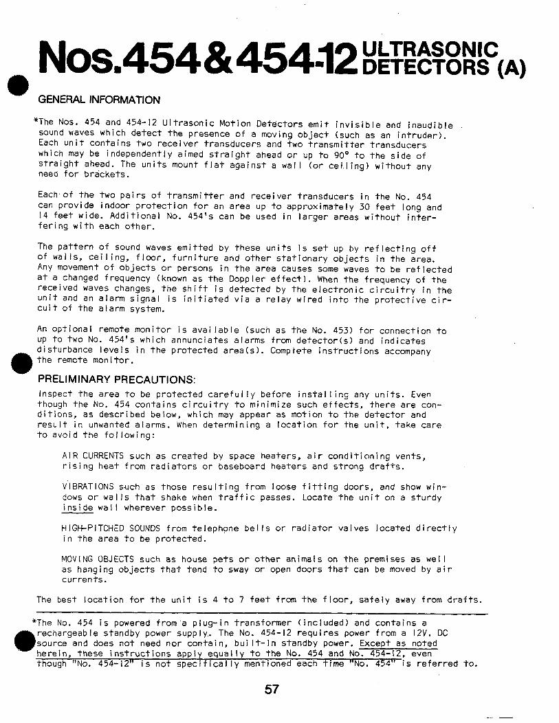
Diagram 1: TYPICAL COVERAGE PATTERNS
:(--T :
COVERAGE CONSIDERATIONS The pattern of the ultrasonic waves emitted by each pair of transducers in the No. 454 is oblong and at maximum sensitivity has a nominal range of up to 30 feet and a width of approximately 14 feet. Actual coverage, however, is affected by these factors :
ORIENTATION AND AIMING: With the No. 454 mounted with its long dimension vertical, each of its transmitter and receiver transducers can be aimed straight ahead or up to 90° to the side.
SURFACE REFLECTION: In areas that have highly reflective surfaces, coverage is greater because the surfaces are hard and easily reflect ultrasonic waves. Glass, tile floors, mirrors, walls and most solid surface areas are considered ref I ect’i ve surfaces.
Surfaces containing soft, sound-absorbing material tend to reduce the range of the unit. Examples of this kind of surface are carpeted floors, drape-. ies, heavy plush furniture, etc.
HUM I DI TY AND .TEMPERATURE: Ultrasonic waves are affected by atmospheric humid- ity and temperature. Between the best and worst combinations of conditions, range can change by over 50%.
TYPICAL LAYOUTS By keeping in mind the aforementioned considerations and other factors (mentioned below) the. installation may be laid out.
Any number of No. 454’s may .be placed in the same area without interfering with each other as long as the following basic positioning rules are observed:
I. Do not direct units at each other unless the distance between them exceeds 60 feet. Diagram 2a illustrates this.
58
t
NOTE: Pattern direction is determined by 8 -\ /’
\\ ‘\ \ , ‘1 ? I
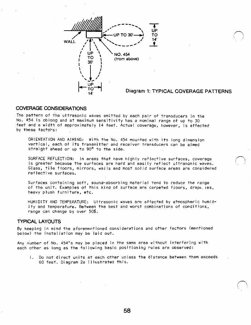
aiming of transducers, not necessarily by direction unit faces.
I *-\ \ -I ; \ \ \ I I,/’
f / I,
I/ ,5’
b. \ H _------ I ’ r zi --Z- \ \ -1 \ \ a.
./--- CEILING 0
I’ \ 1
\ . / +--
C~
-\
Diagram 2: TYPICAL LAYOUTS
2. Units may be placed on opposite wails or the same wall provided their centers are offset at least I5 feet from each,other if aimed straight ahead. Diagram 2b i I lustrates this.
3. Ceiling mounting is useful in some applications. See Diagram 2c.
4. Back to back installation may be considered. See Diagram 2d.
5. Don’t place units too close together as some range shortening can occur.
INSTALLATION AND WIRING Mounting:
The No. 454 is designed for mounting flat aga are not necessary.
i nst any wal I. Mount i ng brackets
The unit should normally be mounted with its I ong dimens its transducer heads to be aimed to the side or straight desired, however, any mounting position may be used, inc
WIRING CONNECTIONS See Diagrams 3a, 3b and 4. Connections should be made in this order:
on vertical to permit ahead as requi red. If uding ‘cei I ing mounting.
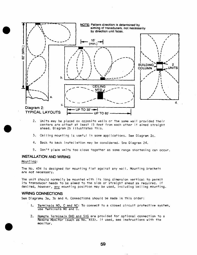
I. Terminals NO, C and NC: To connect to a closed circuit protective system, use termina I s NO and C.
d.
2. Remote Terminals GND and SIG are provided for ,optional connection to a Remote Monitor (such as No. 453). If used, see instructions with the monitor.
12v REMOTE AC NO C NC - GND SIG
TERMINALS IN
N0.454~~79 @?? T?-
NORMALLY CLOSED
PROTECTIVE CIRCUIT
G6JD SiG
RE$TE MONITOR
(OPTIONAL)
SEE INSTRUCTIONS
WITH MONITOR
Diagram 3a: TERMINAL CONNECTIONS, No. 454 Only
12 V.DC REMOTE
NO C NC + - - GND SIG TERMINALS IN
). 4!54-12-
NC t t
NORMALLY CLOSED
PROTECTIVE ,CIRCUIT
GtiD SiG
RE&:TE MONITOR
(OPTIONAL) + - SEE
TO INSTRUCTIONS 12 VDC WITH
SOURCE MONITOR
OBSERVE POLARITY!
Diagram 3b: TERMINAL CONNECTIONS, No. 454-12 Only
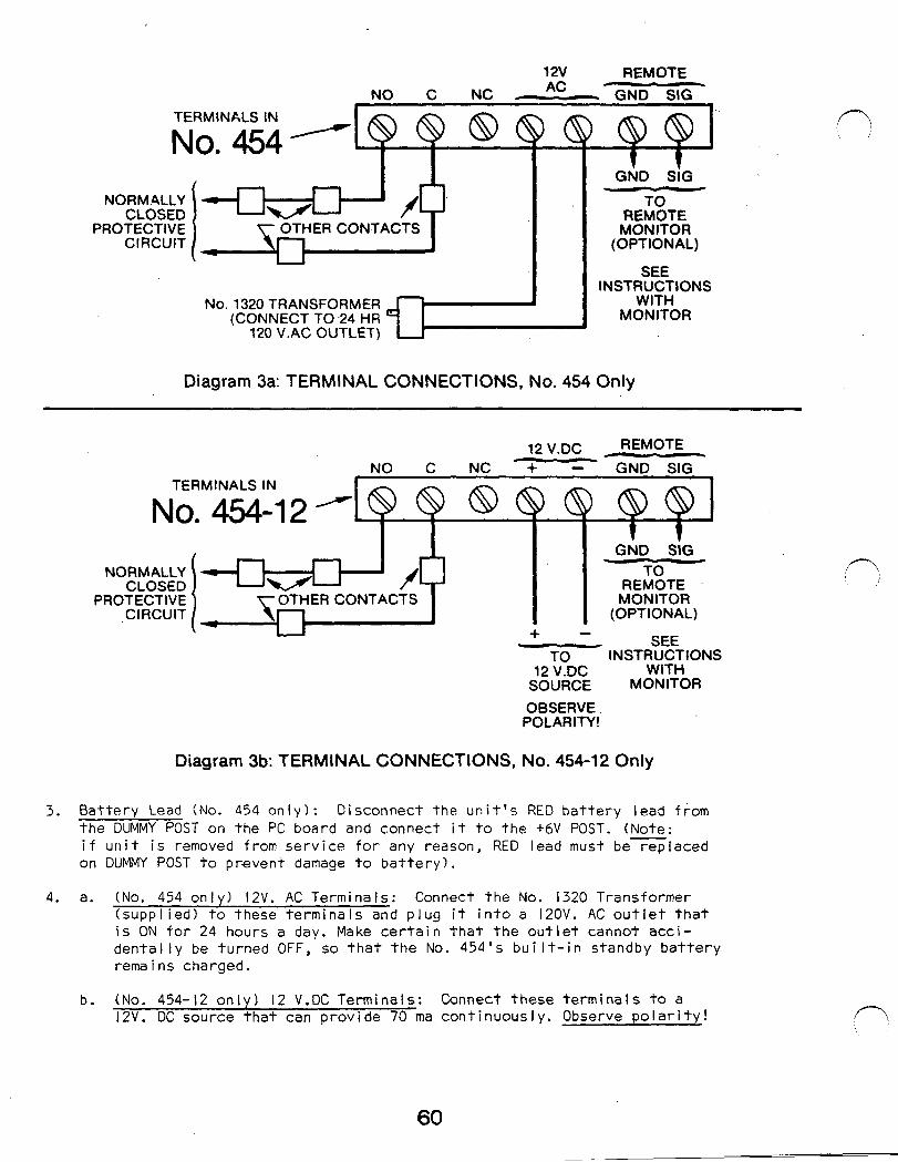
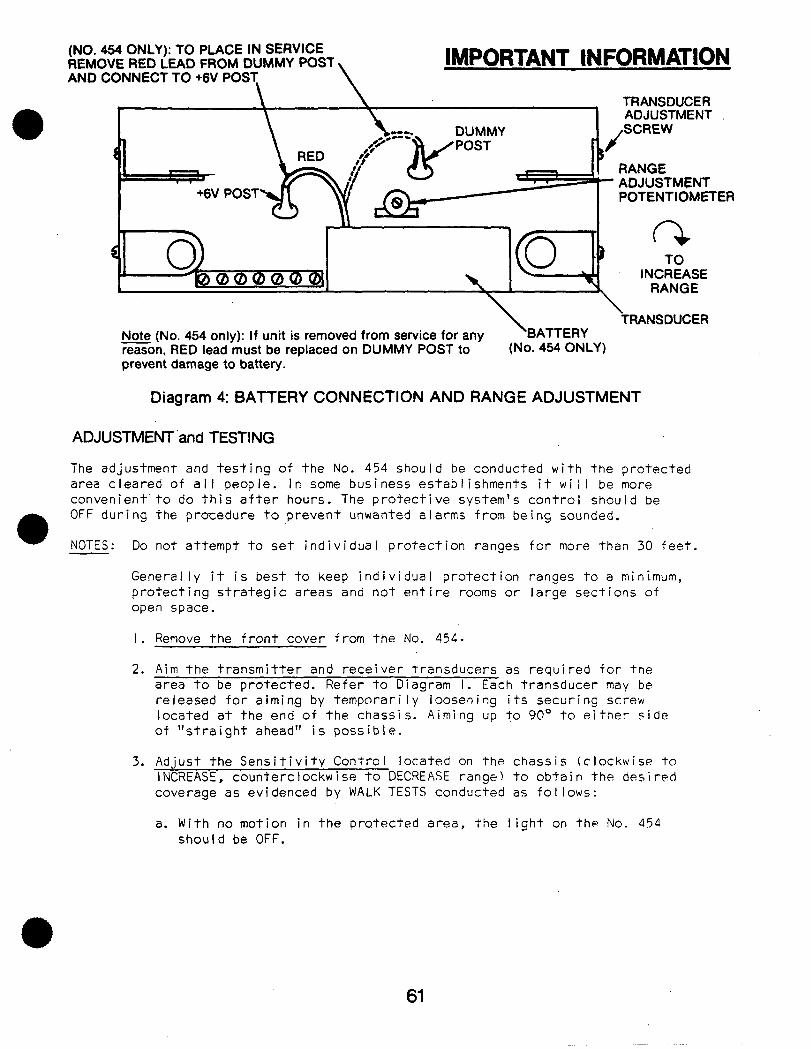
3. Battery Lead (No. 454 only) : Disconnect the unit’s RED battery lead from the DUMMY POST on the PC board and connect it to the +6V POST. (Note: if unit is removed from service for any reason, RED lead must be replaced on DUMMY POST to prevent damage to battery).
4. a. (No. 454 on I y) I2V. AC Termi na Is: Connect the No. 1320 Transformer (supplied) to these terminals and plug it into a 12OV. AC outlet that is ON for 24 hours a day. Make certain that the outlet cannot acci- dentally be turned OFF, so that the No. 454’s built-in standby battery rema i ns charged.
b. (No. 454-12 only) I2 V.DC Terminals: Connect these terminals to a 12V. DC source that can provide 70 ma continuously. Observe polarity!
60
(NO. 464 ONLY): TO PLACE IN SERVICE REMOVE RED LEAD FROM DUMMY POST AND CONNECT TO +6V POST \
IMPORTANT tNFORMATION
I
POST
\
1 TRANSDUCER
\ ADJUSTMENT
DUMMY ,SCREW
\ TRANSDUCER
Note (No. 454 only): If unit is removed from service for any BATTERY reason, RED lead must be replaced on DUMMY POST to (No. 454 ONLY) prevent damage to battery.
Diagram 4: BATTERY CONNECTION AND RANGE ADJUSTMENT
ADJUSTMENT ‘and TESTING
The adjustment and testing of the No. 454 should be conducted with the protected area cleared of all people. In some business establishments it will be more convenient’to do this after hours. The protective system’s control should be OFF during the procedure to prevent unwanted alarms’from being sounded.
NOTES : Do not attempt to set individual protection ranges for more than 30 feet.
Generally it is best to keep individual protection ranges to a minimum, protecting strategic areas and not entire rooms or large sections of open space.
I .
2.
3.
Remove the front cover from the No. 454.
Aim the transmitter and receiver transducers as required for the area to be protected. Refer to Diagram I. Each transducer may be released for aiming by tsmporari ly loosening its securing screw located at the end of the chassis. Aiming up to 90° to either side of “straight ahead” is possible.
Adjust the Sensitivity Control located on the chassis (clockwise to INCREASE, counterclockwise to DECREASE range) to obtain the desired coverage as evidenced by WALK TESTS conducted as follows:
a. With no motion in the protected area, the light on the No. 454 should be OFF.
61
4.
5.
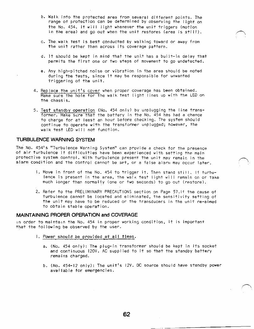
b. Walk into the protected area from several different points. The range of protection can be determi ned by observing the I ight on the No. 454. It will light whenever the unit triggers (motion in the area) and go out when the unit restores (area is still).
c. The. wal k test is best conducted by walking toward or away from the unit rather than across its coverage pattern.
d. It should be kept in mind that the uni.t has a bui It-in delay that permits the first one or two steps of movement to go undetected.
e. Any high-pitched noise or vibration in the area should be noted during the tests, since it may be responsible for unwanted triggering of the unit.
Rep I ace the un i t’ s ccver when proper coverage has been obta i ned . Make sure the hole for the walk test light lines up with the LED on the chass i s.
Test standby operation (No. 454 only) by unplugging the line trans- former. Make sure that the battery in the No. 454 has had a chance to charge for at least an hour before checking. The system should continue to operate with the transformer unplugged; however, the walk test LED will not function.
TURBULENCE WARNING SYSTEM
The No. 454’s “Turbulence Warning System” can provide a check for the presence of air turbulence if difficulties have been experienced with setting the main protective system control. With turbulence present the unit may remain in the alarm condition and the control cannot be set, or a false alarm may occur later.
I. Move in front of the No. 454 to trigger it. Then stand still. if turbu- lence is present in the area, the waik test light will remain on or take much longer than normally (one or two seconds) to go out (restore).
2. Refer to the PRELIMINARY PRECAUTIONS section pn Page 57.lf the cause of turbulence cannot be located and eliminated, the sensitivity setting of the unit may have to be reduced or the transducers in the unit re-aimed to obtain stable operation.
MAINTAINING PROPER OPERATION and COVERAGE In order to maintain the No. 454 in proper working condition, it is important that the following be observed by the user.
I. Power should be provided at all times.
a. (No. 454 only): The plug-in transformer should be kept in its socket and continuous l2OV. AC supplied to it so that the standby battery rema i ns charged.
b. (No. 454-12 only): The unit’s l2V. DC source should have standby power avai lable for emergencies.
62
2. Units should never be relocated without the advice or assistance of the alarm service company.
3. The physical surroundings of the protected area should not be changed. If furniture or stock is moved, or air-conditioning or additional heat- ing is installed, the system may have to be readjusted by the alarm ser- vi ce company.
4. The unit is ON 24 hours a dav. No alarm will be initiated while the main protective system is OFF.
Physical:
Electrical:
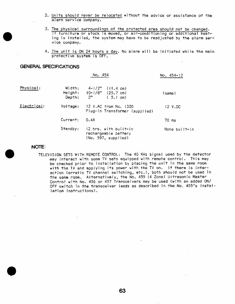
GENERAL SPECIFICATIONS
Width: Height:
Depth :
Vo I tage :
Current:
Standby:
NOTE: -
No. 454 No. 454-12
4- I /2” (II.4 cm) IO- I /8” (25.7 cm) 2” ( 5. I cm1
12 V.AC from No. 1320 Plug-in Transformer (supplied)
( same 1
12 V.DC
0.4A 70 ma
12 hrs. with built-in rechargeab le battery (No. 597, supp I ied)
None built-in
TELEVISION SETS WITH REMOTE CONTROL: The 40 KHz signal used by the detector may interact with some TV sets equipped with remote control. This may be checked prior to installation by placing the unit in the same room with the 1V and applying its power with the TV on. If there is inter- action (erratic TV channel switching, etc.), both should not be used in the same room. Alternatively, the No. 455 (4 Zone) Ultrasonic Master Control with No. 456 or 457 Transceivers may be used‘twith an added ON/ OFF switch in the transceiver leads as described in the No. 455’s Instal- lation Instructions).
63
TROUBLE 1:
A.
B.
C.
D.
E.
TROUBLE 2:
A.
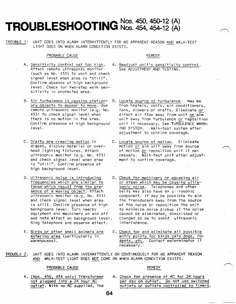
UNIT GOES INTO ALARM INTERMITTENTLY FOR NO APPARENT REASON AND WALK-TEST LIGHT GOES ON WHEN ALARM CONDITION EXISTS.
PROBABLE CAUSE
Sensitivity control set too high. Attach remote ultrasonic monitor (such as No. 453) to unit and check signal level when area is “stil I”. Confirm absence of high background level. Check for two-step walk sen- sitivity in protected area.
Air turbulence is causinq station- cry ob.iects to appear to move. Use -- remote ultrasonic monitor (e.g. No. 453) to check signal level when there is no motion in the area. Confirm presence of high background level _
Drafts are creating motion in -- drapes, display materialor over- head lighting fixtures. Attach ultrasonic monitor (e.g. No. 453) and check signal level when area is ‘!st i I I ‘I. Conf i rm presence of high background level.
Ultrasonic noise is introducinq frequencies w?lich are similar to those which result from the pre- sence of a moving object. Attach ultrasonic monitor (e.g. No. 453) and check signal level when area is still. Confirm presence of high background level. Turn nearby equipment and machinery on and off and note effect on background level Ring telephone and observe effect.
Birds or other small animals are_ enter i n q area (particularly in warehouses I.
A.
B.
C.
D.
E.
REMEDY --
Readjust unit’s sensit.ivity control. See ADJUSTMENT AND TESTING.
Locate source of turbulence. May be -- from heaters, vents, air conditioners, fans, blowers or drafts. Eliminate or direct air flow away from unit or aim unit away from turbulence or reposition unit if necessary. See TURBULENCE WARN- I NG SYSTEM. Wa I k-test system after adjustment to confirm coverage.
Locate source of motion. El iminate motion oraim unit away from source of motiZ or reposition unit if ne- cessa ry . Walk-test unit after adjust- ment to confirm coverage.
Check for machinery or escaping air or steam which may be causing ultra- sonic noise. Telephones and other bells may also have an u:;rasonic component. It may be possible to aim the transducers away from the source of the noise or reposition the unit to minimize noise pickup if the noise cannot be eliminated, diminished or changed so as to avoi d ultrasonic i nterf erence.
Check for and eliminate all possible ent.t-y points for birds cats dogs, ro- dents, etc. Contact exterminator if necessary .
UNIT GOES INTO ALARM INTERMITTENTLY OR CONTINUOUSLY FOR NO APPARENT REASON AND WALK-TEST LIGHT DOES NOT COME ON WHEN ALARM CONDITION EXISTS.
PROBABLE CAUSE REMEDY
(Nos. 450, 454 only) Transformer A. Check for presence of AC for 24 hours not plugged into a 24 hour AC per day on outlet. Do not use switched outlet. With no AC supplied, the outlets or outlets controlled by timers. -
64
:
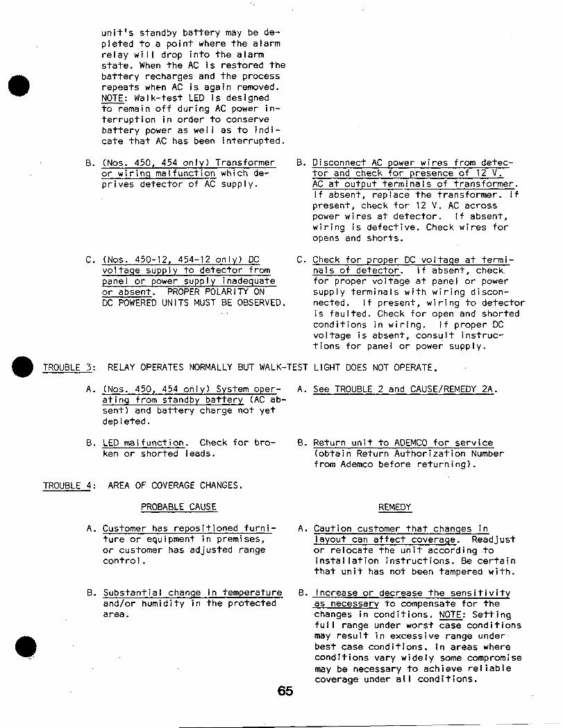
unit’s standby battery may be de- pleted to a point where the alarm relay will drop into the a,larm state. When the AC is restored the battery recharges and the process repeats when AC is again removed. NOTE: Walk-test LED is designed to remain off during AC power in- terruption in order to conserve battery power as well as to indi- cate that AC has been interrupted.
B.
C.
TROUBLE 3 : -
A.
B.
TROUBLE 4:
A.
8.
(Nos. 450, 454 only) Transformer or wirinq malfunctiofi which de- prives detector of AC supply.
(Nos. 450-12, 454-12 only) DC voltage supply to detector from panel or power supply inadequate or absent. PROPER POLARITY ON DC POWERED UNITS MUST BE OBSERVED.
RELAY OPERATES NORMALLY BUT WALK-TEST
(Nos. 450, 454 only) System oper- A. atinq from standby battery (AC ab- sent) and battery charge not yet depleted.
LED malfunction. Check for bro- B. ken or shorted leads.
AREA OF COVERAGE CHANGES.
PROBABLE CAUSE
Customer has repositioned furni- A. ture or equipment in premises, or customer has adjusted range contra I .
Substantial change in temperature B. and/or humidity in the protected area.
65
B.
C.
Disconnect AC power wires from detec- tor and check for presence of 12 V. AC at output termi na I s of transformer. If absent, replace the transformer. If present, check for 12 V. AC across power wires at detector. If absent, wiring is defective. Check wires for opens and shorts.
Check for proper DC voltaqe at termi- nals of detector. If absent, check. for proper voltage at panel or power supply terminals with wiring discon- netted. If present, wiring to detector is faulted. Check,for open and shorted conditions in wiring. If proper DC voltage is absent, consult instru? tions for panel or power supply.
LIGHT DOES NOT OPERATE.
See TROUBLE 2 and CAUSE/REMEDY 2A.
Return unit to ADEMCO for service (obtain Return Authorization Number from Ademco before returning).
REMEDY
Caution customer that chanqes in layout can affect coverage. Readjust or relocate the unit according .to installation instructions. Be certain that unit has not been tampered with.
Increase or decrease the sensitivity as necessary to compensate for the changes in conditions. NOTE: Setting full range under worst case conditions may result in excessive range under best case conditions. In areas where conditions vary widely some compromise may be necessary to achieve reliable coverage under all conditions.
TROUBLE 5: UNIT DOES NOT APPEAR
PROBABLE CAUSE
A. Unit is not receiving power.
B.
TROUBLE 6:
A.
TO BE OPERATING.
REMEDY
/I A. Check for presence of appropriate
input voltaqe at terminals of unit. ,;
(Nos. 450, 454) Be certain that unit’s battery lead has been moved from DUMMY (shipping/storage) POST to its active +6 V. DC POST.
(Nos. 450-12, 454-12) Be certain that the unit is receiving 12 volts DC (oh- serve polarity) at the corresponding terminals. See TROUBLE 2, REMEDY C.
Wait one-half hour after restoring voltage before setting range sdjust- ments.
Sensitivity is at a MINIMUM. B. Increase sensitivity control to achieve proper wa I k.-test. Use of remote ill tra- sonic monitor (e.g. No. 453) would be helpful in avoiding trouble caused by background conditions. See TROUBLE 1 and its CAUSES and REMEDIES.
SOME REMOTE CONTROL TELEVISIONS BEHAVE ERRATICALLY AFTER OF AN ULTRASONIC UNIT.
PROBABLE CAUSE
The ultrasonic detector is opera- A. ting on a frequency similar to that of some remote control tele-
THE I NSTALLAT I ON :-,
REMEDY --
See “INTERFERENCE WITH TELEVISION SETS EQUIPPED WITH REMOTE CONTROL” on page 111 of this section.
visions.
66
ULTRASONIC INTERFERENCE WITH REMOTE CONTROL TELEVISIONS - NOS. 450 & 454 (A) If it is found that an Ultrasonic Detector interferes with the remote.control portion of a television set, the following can be done in the field to circumvent this:
f\ remote switch can be placed in series with one leg of the circuit running from the transmitting transducer to the PC board. You will notice that there are two wires running from this transcducer to the PC board. The wire most likely to be the correct wire to cut and haV8 a switch installed in series with, is the white wire. lt is important to make ‘sure that this wire is correct however. Please use the steps below for proper installation of the switch. Once the switch is connected to the unit, the transmitting transducer will be switched off and the 40KC no longer transmitting. It must be noted that this switch is not supervi sed and therefore, we recommend that if this is going to be done a double- pole single-throw DPST switch be used; one to open the line to the transducer and the other to open the protective circuit, so that the alarm system will not properly arm unless the switch is closed.
WIRING INSTRUCTIONS ‘I .
2.
3.
4.
5.
6.
7.
Disconnect all power (transformer and battery if used) from the Nos.450 and 454.
Locate transmitting transducer. This is the transducer with the red dot on the rear.
Locate the correct wire in which the switch is to be series connected. To accomplish this, take a standard ohm meter set to the RXI scale and without removing any wires connect one probe to the case of the transmitting transducer and the other to the post where the wires from the transducer are connected to the PC board. Checking one post at a time, you will locate the one that shows continuity and that.is the correct wire to be cut. In almost all cases the white wire will be. the correct wire.
Making sure that the wire to be used when running your On/Off Switch is no smaller than 20 gauge, a twisted pair and no more than IO’, cut the correct wire and make your connections using a single-pole, single-throw switch. (If supervision is required, use a double-pole single-throw (DPST) switch as mentioned above.)
In the case of a No. 454, there are two transmitting transducers and the wire showing continuity between the PC board and the case of the transducers are common, and the two wires can be connected together allowing you to use one switch to turn the trans- ducers on and off. This is accomplished by cutting both correct wires and Splicing them together. Take one side of your switch and connect it to your splice and the other side of the switch goes to one of the posts where one of the correct wires was removed. See Diagram.
If the wiring has been completed correctly, with the switch in the OFF position, a TV set that would normally have been affected will no longer receive the 40KC signal. With the switch turned on, the Ultrasonic unit will work as designed.
ln the instance where the ultrasonic frequencies emitted by the Nos. 450 and 454 act to turn on the television set and not simply change its channels, this method will not work, since, whenever the alarm system is armed and the Ultrasonic unit(s) is transmitting, the television set may be inadvertently turned on. In such cases, the transmitter may have to be re-aimed or relocated to another position.
111
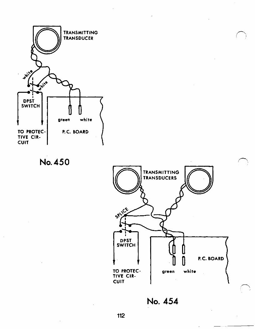
TRANSMITTING TRANSDUCER
green white
TO PROTEC- TIVE CIR- CUIT
P. C. BOARD
No. 450
ml TRANSMITTING TRANSDUCERS
TO PROTEC- TIVE CIR- CUIT
green white
No. 454
112