Modelling, Simulating and Verifying Turing-Powerful … Simulating and Verifying Turing-Powerful...
15
Modelling, Simulating and Verifying Turing-Powerful Strand Displacement Systems Matthew R. Lakin and Andrew Phillips Microsoft Research, Cambridge, CB3 0FB, UK [email protected] Abstract. We demonstrate how the DSD programming language can be used to design a DNA stack machine and to analyse its behaviour. Stack machines are of interest because they can efficiently simulate a Turing machine. We extend the semantics of the DSD language to sup- port operations on DNA polymers and use our stack machine design to implement a non-trivial example: a ripple carry adder which can sum two binary numbers of arbitrary size. We use model checking to verify that the ripple carry adder executes correctly on a range of inputs. This provides the first opportunity to assess the correctness and kinetic prop- erties of DNA strand displacement systems performing Turing-powerful symbolic computation. 1 Introduction Biomolecular computation devices can interface directly with living tissue [1], opening up exciting new possibilities for autonomous medical intervention at the cellular level. The programmable nature of DNA makes it ideally suited as a material to implement such biomolecular computers. As techniques for DNA synthesis and manipulation continue to improve, we can look towards using DNA to implement more sophisticated computational functions. Classical work on computability theory has produced a number of equivalent universal computational models, such as Turing machines [2] and stack machines. Both of these paradigms are based on symbolic computation, where computation proceeds via the manipulation of abstract mathematical symbols which denote data values. These paradigms have the virtues of simplicity and compactness, as simple data structures are modified in-place. Nucleic acids are excellent ma- terials for implementing symbolic computation, because distinct symbols can be straightforwardly represented as distinct, non-interfering nucleotide sequences, and data structures can be directly realized in the physical structure of the DNA species. In this paper we study the design and analysis of biomolecular implementa- tions of universal symbolic computation. Our chosen framework for molecular computation is DNA strand displacement [3], which is an established technique for the principled design of DNA computing systems. Our starting point is the work of Qian et al. [4], who proposed a design of a stack machine using DNA strand displacement. A stack machine consists of finitely many stacks (first-in, L. Cardelli and W. Shih (Eds.): DNA 17, LNCS 6937, pp. 130–144, 2011. c Springer-Verlag Berlin Heidelberg 2011
Transcript of Modelling, Simulating and Verifying Turing-Powerful … Simulating and Verifying Turing-Powerful...
Modelling, Simulating and VerifyingTuring-Powerful Strand Displacement Systems
Matthew R. Lakin and Andrew Phillips
Microsoft Research, Cambridge, CB3 0FB, [email protected]
Abstract. We demonstrate how the DSD programming language canbe used to design a DNA stack machine and to analyse its behaviour.Stack machines are of interest because they can efficiently simulate aTuring machine. We extend the semantics of the DSD language to sup-port operations on DNA polymers and use our stack machine design toimplement a non-trivial example: a ripple carry adder which can sumtwo binary numbers of arbitrary size. We use model checking to verifythat the ripple carry adder executes correctly on a range of inputs. Thisprovides the first opportunity to assess the correctness and kinetic prop-erties of DNA strand displacement systems performing Turing-powerfulsymbolic computation.
1 Introduction
Biomolecular computation devices can interface directly with living tissue [1],opening up exciting new possibilities for autonomous medical intervention atthe cellular level. The programmable nature of DNA makes it ideally suited asa material to implement such biomolecular computers. As techniques for DNAsynthesis and manipulation continue to improve, we can look towards using DNAto implement more sophisticated computational functions.
Classical work on computability theory has produced a number of equivalentuniversal computational models, such as Turing machines [2] and stack machines.Both of these paradigms are based on symbolic computation, where computationproceeds via the manipulation of abstract mathematical symbols which denotedata values. These paradigms have the virtues of simplicity and compactness,as simple data structures are modified in-place. Nucleic acids are excellent ma-terials for implementing symbolic computation, because distinct symbols can bestraightforwardly represented as distinct, non-interfering nucleotide sequences,and data structures can be directly realized in the physical structure of the DNAspecies.
In this paper we study the design and analysis of biomolecular implementa-tions of universal symbolic computation. Our chosen framework for molecularcomputation is DNA strand displacement [3], which is an established techniquefor the principled design of DNA computing systems. Our starting point is thework of Qian et al. [4], who proposed a design of a stack machine using DNAstrand displacement. A stack machine consists of finitely many stacks (first-in,
L. Cardelli and W. Shih (Eds.): DNA 17, LNCS 6937, pp. 130–144, 2011.c© Springer-Verlag Berlin Heidelberg 2011
Modelling, Simulating and Verifying 131
first-out memory storage) and a finite state machine which can add symbols to(push), and remove symbols from (pop), the top of these stacks. In [4] the stackdata structures have a direct physical representation as DNA polymers whichcan interact at one end only. This design is a simple and elegant translation ofa universal scheme for symbolic computation into DNA, which can be used toefficiently simulate a Turing machine [2].
We tackle the formal design and analysis of universal DNA computers by en-coding them in the DSD programming language [5]. This is a domain-specificlanguage with a well-defined operational semantics that reflects the key assump-tions of strand displacement systems. DSD has previously been used to model arange of strand displacement devices, including logic gates and chemical reactionnetworks. However, previous versions of DSD did not support the formation ofextensible polymers, which are required to encode stack data structures in DNA.Furthermore, the DSD simulation algorithm required all models to be compiledto a fixed set of reactions and was therefore unable to simulate Turing-powerfulcomputation, which can generate potentially unbounded numbers of reactions.Hence we extend the DSD semantics and simulation algorithm to support theformation of linear hetropolymers.
This paper is structured as follows. Section 2 presents an extension of the DSDlanguage syntax and semantics [5] to model the formation of linear DNA het-eropolymers, while Section 3 presents a stochastic simulation algorithm, based on[6], for DNA strand displacement systems involving polymers. Section 4 presentsan encoding of a stack machine design in the DSD language which is optimisedfor mechanical verification. Finally, Section 5 presents an implementation of aclassic circuit from digital electronics, a ripple carry adder, which computes thesum of two binary numbers of arbitrary size, including results from stochasticsimulations and model-checking which provide evidence that the DNA imple-mentation of the adder is correct. To our knowledge, this is the largest DNAstrand displacement system to be formally verified.
2 Polymers in DSD
The DSD language was introduced in [5] as a means of formalising the designsof DNA strand displacement systems. Here we recap the basics and extend thesemantics to allow polymerisation reactions between complexes.
The syntax of the DSD language is defined in terms of domains M and domainsequences S, L, R. A domain M represents a nucleotide sequence with explicitinformation about the orientation of its 3’ and 5’ ends. We assume that distinctdomains are mapped to distinct, non-interfering nucleotide sequences using es-tablished techniques [7]. A domain can be a long domain N or a short domainN^ (shown in black in images). We assume that toeholds are sufficiently short tohybridize reversibly (4–10nt) whereas long domains are sufficiently long to hy-bridize irreversibly (>20nt). A domain sequence S is a concatenation of finitelymany domains with the same orientation, whereas domain sequences L and R canpotentially be empty. The complement S* of a domain sequence S is the domainsequence that hybridizes with S via Watson-Crick complementarity.
132 M.R. Lakin and A. Phillips
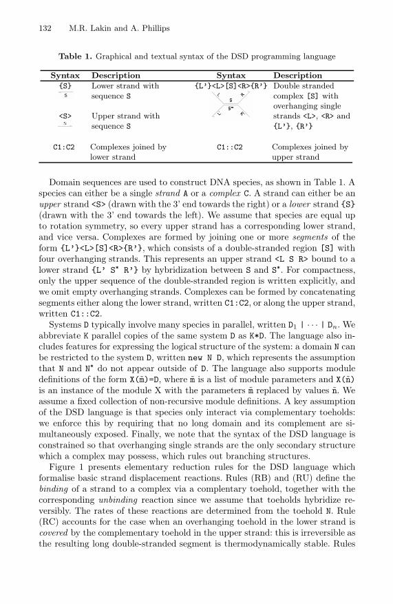
Table 1. Graphical and textual syntax of the DSD programming language
Syntax Description Syntax Description{S}
<S>
Lower strand withsequence S
Upper strand withsequence S
{L’}<L>[S]<R>{R’} Double strandedcomplex [S] withoverhanging singlestrands <L>, <R> and{L’}, {R’}
C1:C2 Complexes joined bylower strand
C1::C2 Complexes joined byupper strand
Domain sequences are used to construct DNA species, as shown in Table 1. Aspecies can either be a single strand A or a complex C. A strand can either be anupper strand <S> (drawn with the 3’ end towards the right) or a lower strand {S}(drawn with the 3’ end towards the left). We assume that species are equal upto rotation symmetry, so every upper strand has a corresponding lower strand,and vice versa. Complexes are formed by joining one or more segments of theform {L’}<L>[S]<R>{R’}, which consists of a double-stranded region [S] withfour overhanging strands. This represents an upper strand <L S R> bound to alower strand {L’ S* R’} by hybridization between S and S*. For compactness,only the upper sequence of the double-stranded region is written explicitly, andwe omit empty overhanging strands. Complexes can be formed by concatenatingsegments either along the lower strand, written C1:C2, or along the upper strand,written C1::C2.
Systems D typically involve many species in parallel, written D1 | · · · | Dn. Weabbreviate K parallel copies of the same system D as K*D. The language also in-cludes features for expressing the logical structure of the system: a domain N canbe restricted to the system D, written new N D, which represents the assumptionthat N and N* do not appear outside of D. The language also supports moduledefinitions of the form X(m)=D, where m is a list of module parameters and X(n)is an instance of the module X with the parameters m replaced by values n. Weassume a fixed collection of non-recursive module definitions. A key assumptionof the DSD language is that species only interact via complementary toeholds:we enforce this by requiring that no long domain and its complement are si-multaneously exposed. Finally, we note that the syntax of the DSD language isconstrained so that overhanging single strands are the only secondary structurewhich a complex may possess, which rules out branching structures.
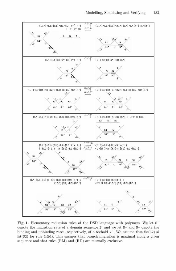
Figure 1 presents elementary reduction rules for the DSD language whichformalise basic strand displacement reactions. Rules (RB) and (RU) define thebinding of a strand to a complex via a complentary toehold, together with thecorresponding unbinding reaction since we assume that toeholds hybridize re-versibly. The rates of these reactions are determined from the toehold N. Rule(RC) accounts for the case when an overhanging toehold in the lower strand iscovered by the complementary toehold in the upper strand: this is irreversible asthe resulting long double-stranded segment is thermodynamically stable. Rules
Modelling, Simulating and Verifying 133
{L1’}<L1>[S1]<R1>{L’ N^* R’}| <L N^ R>
RB,N+−→RU ,N-←−
{L1’}<L1>[S1]<R1>:{L’}<L>[N^]<R>{R’}
{L’}<L>[S]<N^ R>{N^* R’}RC ,N~−→ {L’}<L>[S N^]<R>{R’}
{L’}<L>[S1]<S R2>:<L1>[S S2]<R>{R’}RM ,S~−→RM ,S~←−
{L’}<L>[S1 S]<R2>:<L1 S>[S2]<R>{R’}
{L’}<L>[S1]<S R>:<L2>[S]<R2>{R’}RD,S~−→ {L’}<L>[S1 S]<R>{R’} | <L2 S R2>
{L1’}<L1>[S1]<R1>{L’ N^* R’}| {L2’}<L N^ R>[S2]<R2>{R2’}
RBP,N+−→RUP,N-←−
{L1’}<L1>[S1]<R1>{L’}:<L>[N^]<R>{R’}::[S2]<R2>{R2’}
{L’}<L>[S1]<S R>:<L2>[S]<R2>{R’}::{L3’}[S2]<R3>{R3’}
RDP,S~−→ {L’}<L>[S]<R>{R’} |<L2 S R2>{L3’}[S2]<R3>{R3’}
Fig. 1. Elementary reduction rules of the DSD language with polymers. We let S~denote the migration rate of a domain sequence S, and we let N+ and N- denote thebinding and unbinding rates, respectively, of a toehold N^. We assume that fst(R2) �=fst(S2) for rule (RM). This ensures that branch migration is maximal along a givensequence and that rules (RM) and (RD) are mutually exclusive.
134 M.R. Lakin and A. Phillips
(RM) and (RD) define branch migration and strand displacement reactions, re-spectively. In each of these, the overhanging junction in the upper strand per-forms a random walk which, in the case of rule (RD), completely displaces astrand from the complex. Note that branch migration is a reversible processwhereas strand displacement is irreversible.
The final two rows in Figure 1 present additional reduction rules which donot feature in previous published semantics for the DSD language [5]. Theserules permit complexes to interact with each other to form larger complexeswhich we refer to as polymers. Rule (RBP) allows two complexes to bind on ashared toehold to form a longer complex, and rule (RUP) allows the larger com-plex to break apart when the toehold unbinds. Rule (RDP) extends the stranddisplacement rule (RD) to the case where the displaced strand was previouslyholding two complexes together. Note that the reduction rules ensure that theonly toeholds which may interact are located in the main trunk of the complex asopposed to in the overhangs: this prevents the formation of branching structureswhile permitting the growth of linear heteropolymers.
The rules presented in Figure 1 define the basic forms of reduction in theextended DSD language. However, these reactions may take place within largercontexts, so to complete the language semantics we require some additionalcontextual rules. These include adding segments on either side of the reactingsegment, mirroring the species horizontally and vertically, and rotating them. Weomit the contexutal rules here for reasons of space. In the case of rule (RBP), wenote that the overhangs containing the complementary toeholds must appear atthe very ends of the complexes: in other words, polymers can only interact end-to-end. This can be formalised by a careful choice of contextual rules which onlyallow additional structure at one end of interacting complexes. This restrictionis necessary to prevent branching structures from arising dynamically.
3 Stochastic Simulation of Polymerising Systems
The standard Gillespie algorithm for exact stochastic simulation [8] requiresthat the entire chemical reaction network (CRN) of all possible reactions be-tween reachable chemical species must be known before the simulation begins.However, in the case of DNA strand displacement systems with polymers we can-not necessarily pre-compute the CRN because it may be infinite, as we could (inprinciple) keep adding monomers to produce an ever-increasing polymer chain.
We avoid this problem by using the just-in-time simulation algorithm from [6].This is an extension of the Gillespie algorithm in which compilation of speciesinteractions is interleaved with simulation steps. The just-in-time simulationalgorithm can be summarised as follows:
1. Compute the CRN of all possible initial reactions between the initial speciesonly, without recursively computing reactions involving the products of thoseinitial reactions.
2. Compute reaction propensities according to the Gillespie algorithm, and ran-domly select the next reaction with probability proportional to its propensity.
Modelling, Simulating and Verifying 135
3. Execute the next reaction by modifying the species populations and incre-menting the simulation time according to the Gillespie algorithm.
4. If executing the reaction produced any new species which have not yet beenseen in the system then compute any interactions between the new speciesand the existing species in the system, and expand the CRN accordingly.
5. Repeat from step 2.
Thus we dynamically update the set of possible reactions as the simulation pro-ceeds, rather than computing all possible reactions up front. Hence we computeonly the needed subgraph of the CRN. This can offer significant speedups whenthe CRN is very large, and is the only feasible approach when the CRN is infi-nite, as in the case of most polymerising systems. The stochastic simulation isexact since all probabilities are computed exactly at each step.
4 Modelling Stack Machines in DSD
In this section we present a novel stack design which is a variant of the stackencoding from [4]. Our design was formalised, visualised and analysed using theVisual DSD tool1. Our primary goal in designing a new stack implementation isto produce an encoding which is amenable to automated verification. Thus weaim to eliminate speculative stack manipulation reactions and irreversible stepsin reaction gates which could occur at any time after the outputs are produced.
4.1 A Variant Stack Encoding
The stack design from [4] has the property that fuel monomers specific to thevarious symbols that might be pushed onto the stack are continually interactingwith the stack, in the hope that the symbol strand itself may arrive to completethe reaction, as in Figure 3 of [4]. Furthermore, that Figure shows that the fuelstrands which can deconstruct the stack are also continually interacting with thestack, in the hope that other species may arrive to complete the reaction. Thismeans that there are always a large number of possible stack-based interactions,and consequently the graph of possible states for these systems is very largeindeed, making it infeasible to perform analyses such as model checking on theresulting CTMC.
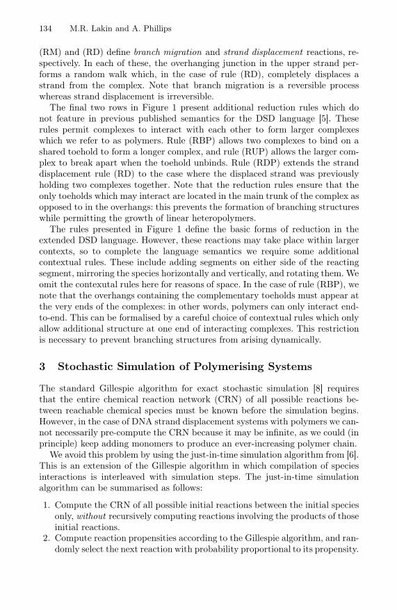
In order to efficiently simulate a Turing machine, more than one stack isneeded for data storage. Thus we must assign a unique type to each stack sothat they can be correctly addressed. In our stack encoding, the stack []::1::0, oftype A, is represented by the following DNA complex. Note that we write thetop of the stack on the right-hand side in our textual notation, to match thevisualisations.
1 Visual DSD is available online at http://research.microsoft.com/dna .
136 M.R. Lakin and A. Phillips
In our encoding, a symbol 1 on stack A is represented by a bound upperstrand of the form <mOne mPushA T^ pPushA pOne>, which we refer to as thepush strand 1A. In this paper we use three kinds of symbol: a special bottomsymbol ⊥ which signals an attempt to pop from an empty stack and two symbolscorresponding to 1 and 0 respectively. Symbols are represented using a history-free scheme similar to that used in [4], except that we separate the nucleotidesequences on either side of the toehold into two long domains: one specific tothe stack type (A here) and one specific to the symbol in question. We restrictourselves to ASCII syntax, writing mX and pX for the negative (towards the 5’end) and positive (towards the 3’ end) sequences, which were referred to as −Xand +X respectively in [4].
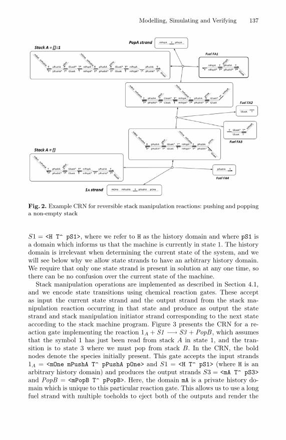
Each stack complex has a single exposed T^ toehold, which serves as theinitiation site for both push and pop reactions. The reaction to pop a symbolfrom stack A is initiated by the pop strand PopA = <mPopA T^ pPopA> whichbegins the clockwise sequence of reversible reactions shown in Figure 2. The fuelspecies FA1–4 are assumed to be present in abundance. Overall, these reversiblereactions interconvert between the stack A = []::1 and the PopA strand, andthe stack A = [] and the 1A strand. The push reaction is initiated by a pushstrand and is obtained as the reverse of the above reaction scheme, reading anti-clockwise in Figure 2. When attempting to pop from an empty stack the reactionsproceed as in Figure 2, except that the resulting complex is not a valid stackstructure. The bottom strand ⊥A = <mBot mPushA T^ pPushA pBot> serves asan error indicator, signalling that an attempt has been made to pop from anempty stack.
Our stack design allows us to initiate pushing or popping by the interactionof a single strand with a stable stack complex, without speculative binding andunbinding reactions as in [4]. Furthermore, we can use a smaller set of backbonemonomers for each stack type: for a given stack type A we only require the fourfuel species FA1–4 from Figure 2 because any symbol can be joined to the mainbackbone of the stack by the common pPushA domain. Hence the number ofdomains required scales with the sum of the number of stacks and the number ofsymbols, whereas in the encoding of [4] it scales with the product (because therethe separate nucleotide sequences denoting the stack and the symbol parts of the<mOne mPushA T^ pPushA pOne> strand are merged so the strand has the form<mOneA T^ pOneA>). In our design it is crucial that the pop strand employs thehistory-free encoding from [4], so it can initiate a leftward displacement reactionto break apart the polymer structure.
4.2 Implementing a Stack Machine in DNA
A stack machine consists of finitely many stacks along with a finite state controlprogram. Thus, a configuration of a stack machine consists of the current stateand the current contents of the stacks. As discussed above, the symbols in agiven stack are encoded in the nucleotide sequences of the overhanging singlestrands attached to the polymer backbone of the corresponding stack complex.We encode the current state of the machine by a single complex of the form
Modelling, Simulating and Verifying 137
Fig. 2. Example CRN for reversible stack manipulation reactions: pushing and poppinga non-empty stack
S1 = <H T^ pS1>, where we refer to H as the history domain and where pS1 isa domain which informs us that the machine is currently in state 1. The historydomain is irrelevant when determining the current state of the system, and wewill see below why we allow state strands to have an arbitrary history domain.We require that only one state strand is present in solution at any one time, sothere can be no confusion over the current state of the machine.
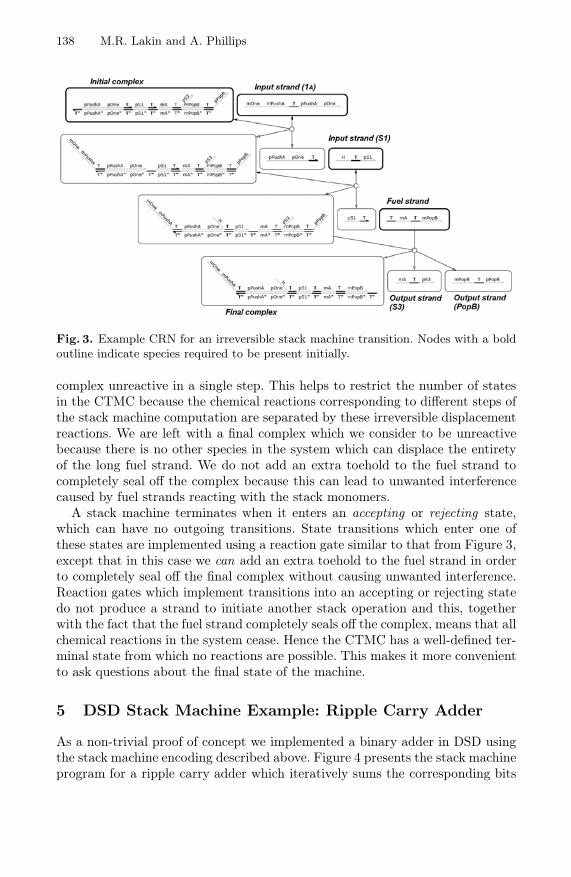
Stack manipulation operations are implemented as described in Section 4.1,and we encode state transitions using chemical reaction gates. These acceptas input the current state strand and the output strand from the stack ma-nipulation reaction occurring in that state and produce as output the statestrand and stack manipulation initiator strand corresponding to the next stateaccording to the stack machine program. Figure 3 presents the CRN for a re-action gate implementing the reaction 1A + S1 −→ S3 + PopB , which assumesthat the symbol 1 has just been read from stack A in state 1, and the tran-sition is to state 3 where we must pop from stack B. In the CRN, the boldnodes denote the species initially present. This gate accepts the input strands1A = <mOne mPushA T^ pPushA pOne> and S1 = <H T^ pS1> (where H is anarbitrary history domain) and produces the output strands S3 = <mA T^ pS3>and PopB = <mPopB T^ pPopB>. Here, the domain mA is a private history do-main which is unique to this particular reaction gate. This allows us to use a longfuel strand with multiple toeholds to eject both of the outputs and render the
138 M.R. Lakin and A. Phillips
Fig. 3. Example CRN for an irreversible stack machine transition. Nodes with a boldoutline indicate species required to be present initially.
complex unreactive in a single step. This helps to restrict the number of statesin the CTMC because the chemical reactions corresponding to different steps ofthe stack machine computation are separated by these irreversible displacementreactions. We are left with a final complex which we consider to be unreactivebecause there is no other species in the system which can displace the entiretyof the long fuel strand. We do not add an extra toehold to the fuel strand tocompletely seal off the complex because this can lead to unwanted interferencecaused by fuel strands reacting with the stack monomers.
A stack machine terminates when it enters an accepting or rejecting state,which can have no outgoing transitions. State transitions which enter one ofthese states are implemented using a reaction gate similar to that from Figure 3,except that in this case we can add an extra toehold to the fuel strand in orderto completely seal off the final complex without causing unwanted interference.Reaction gates which implement transitions into an accepting or rejecting statedo not produce a strand to initiate another stack operation and this, togetherwith the fact that the fuel strand completely seals off the complex, means that allchemical reactions in the system cease. Hence the CTMC has a well-defined ter-minal state from which no reactions are possible. This makes it more convenientto ask questions about the final state of the machine.
5 DSD Stack Machine Example: Ripple Carry Adder
As a non-trivial proof of concept we implemented a binary adder in DSD usingthe stack machine encoding described above. Figure 4 presents the stack machineprogram for a ripple carry adder which iteratively sums the corresponding bits
Modelling, Simulating and Verifying 139
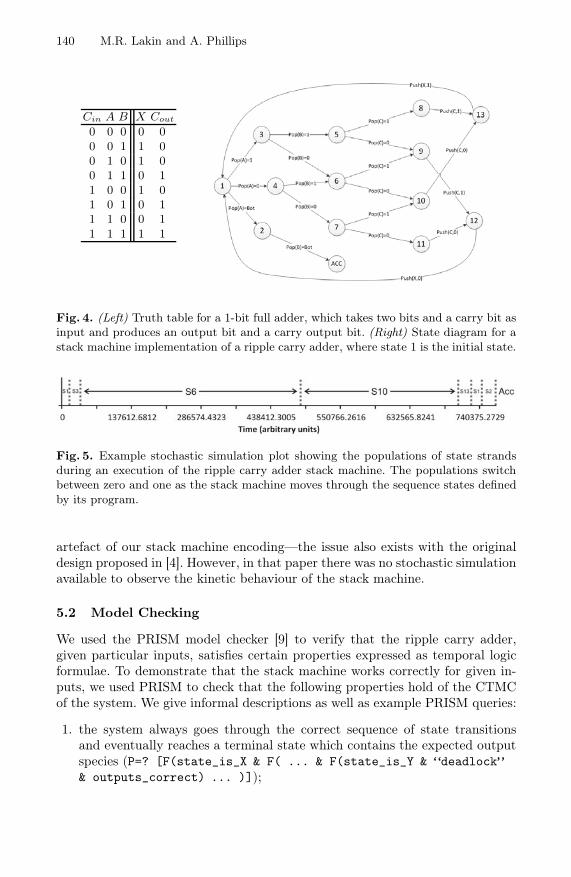
from two binary numbers while maintaining a carry bit. The binary numbersare stored in stacks by using different symbols to denote 0 and 1. States whichinvolve popping from a stack have three outgoing transitions (depending onwhether one, zero or bottom was popped) and states which involve pushing ontoa stack have just one outgoing transition. For the sake of clarity, the state graphin Figure 4 omits a rejecting state along with the transitions into this state: themissing transitions are from state 2 when 0 is popped from stack B, from states3 and 4 when B = [] and from states 5, 6 and 7 when C = []. These transitionssignal an error when the two inputs are of different lengths or when the carrybit is not present as expected.
The machine reads input from stacks A and B (without loss of generalitywe assume that both inputs comprise the same number of bits) and takes itscarry bit from C (initially zero). For each pair of input bits the stack machineimplements a full adder and by iterating the loop we get the effect of a ripplecarry adder. When it terminates, the machine has written the sum of the twoinputs into X along with a carry-out bit in C. Due to the first-in, first-out natureof the stack data structure, the endianness of the output in X is flipped relativeto that of the inputs, though this could be rectified by a subsequent reversingoperation if necessary.
5.1 Stochastic Simulation
Figure 5 presents an example2 of a stochastic simulation for 1-bit addition withinputs A = []::1, B = []::0 and C = []::0. This plot was obtained using thesimulation algorithm described in Section 3. It shows which of the state strandshas population 1 at a given time during the run, which allows us to trace theexecution of the machine. Comparing the sequence of states from this timelinewith the state diagram from Figure 4 shows us that the machine did in factgo through the expected sequence of states. Furthermore, the contents of theoutput stacks at the end of this simulation run were X = []::1 and C = []::0,which agrees with the truth table from Figure 4. Thus we have some preliminaryevidence that our stack machine program is working correctly.
The simulation plot from Figure 5 also gives us some information regardingthe kinetic behaviour of the stack machine implementation. In particular, weobserve that the machine spends far longer in states 6 and 10 than in any of theother states. These bad kinetics are caused by the excess of reaction complexesrelative to the single stack complex. If a strand could bind either to a stack orto a reaction complex, it will be far more likely to bind to the reaction complexas they are present in excess. We can attenuate this effect to an extent in oursimulations by reducing the population of fuels. However, we must strike a bal-ance between providing enough fuel to finish the computation and maintainingreasonable kinetics. Furthermore, in general computations may be arbitrarilylong and we may not know the optimal amount of fuel in advance. This is not an
2 DSD and PRISM source code for the models discussed in Section 5 are availableonline at http://research.microsoft.com/dna/dna17.zip.
140 M.R. Lakin and A. Phillips
Cin A B X Cout
0 0 0 0 00 0 1 1 00 1 0 1 00 1 1 0 11 0 0 1 01 0 1 0 11 1 0 0 11 1 1 1 1
Fig. 4. (Left) Truth table for a 1-bit full adder, which takes two bits and a carry bit asinput and produces an output bit and a carry output bit. (Right) State diagram for astack machine implementation of a ripple carry adder, where state 1 is the initial state.
Fig. 5. Example stochastic simulation plot showing the populations of state strandsduring an execution of the ripple carry adder stack machine. The populations switchbetween zero and one as the stack machine moves through the sequence states definedby its program.
artefact of our stack machine encoding—the issue also exists with the originaldesign proposed in [4]. However, in that paper there was no stochastic simulationavailable to observe the kinetic behaviour of the stack machine.
5.2 Model Checking
We used the PRISM model checker [9] to verify that the ripple carry adder,given particular inputs, satisfies certain properties expressed as temporal logicformulae. To demonstrate that the stack machine works correctly for given in-puts, we used PRISM to check that the following properties hold of the CTMCof the system. We give informal descriptions as well as example PRISM queries:
1. the system always goes through the correct sequence of state transitionsand eventually reaches a terminal state which contains the expected outputspecies (P=? [F(state_is_X & F( ... & F(state_is_Y & “deadlock”& outputs_correct) ... )]);
Modelling, Simulating and Verifying 141
Input A Input B Output X Output C ResultMSB LSB Value MSB LSB Value LSB MSB Value Value
0 0 0 0 0 0 0 0 0 00 0 0 0 1 1 1 0 0 10 0 0 1 0 2 0 1 0 20 0 0 1 1 3 1 1 0 30 1 1 0 0 0 1 0 0 10 1 1 0 1 1 0 1 0 20 1 1 1 0 2 1 1 0 30 1 1 1 1 3 0 0 1 41 0 2 0 0 0 0 1 0 21 0 2 0 1 1 1 1 0 31 0 2 1 0 2 0 0 1 41 0 2 1 1 3 1 0 1 51 1 3 0 0 0 1 1 0 31 1 3 0 1 1 0 0 1 41 1 3 1 0 2 1 0 1 51 1 3 1 1 3 0 1 1 6
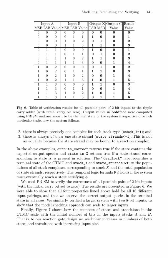
Fig. 6. Table of verification results for all possible pairs of 2-bit inputs to the ripplecarry adder (with initial carry bit zero). Output values in boldface were computedusing PRISM and are known to be the final state of the system irrespective of whichparticular trajectory the system follows.
2. there is always precisely one complex for each stack type (stack_X=1); and3. there is always at most one state strand (state_strands<=1). This is not
an equality because the state strand may be bound to a reaction complex.
In the above examples, outputs_correct returns true if the state contains theexpected output species and state_is_X returns true if a state strand corre-sponding to state X is present in solution. The “deadlock” label identifies aterminal state of the CTMC and stack_X and state_strands return the popu-lations of all stack complexes corresponding to stack X and the total populationof state strands, respectively. The temporal logic formula Fφ holds if the systemmust eventually reach a state satisfying φ.
We used PRISM to verify the correctness of all possible pairs of 2-bit inputs(with the initial carry bit set to zero). The results are presented in Figure 6. Wewere able to show that all four properties listed above hold for all 16 differentinput pairings, and that we observe the correct output species in the terminalstate in all cases. We similarly verified a larger system with two 8-bit inputs, toshow that the model checking approach can scale to larger inputs.
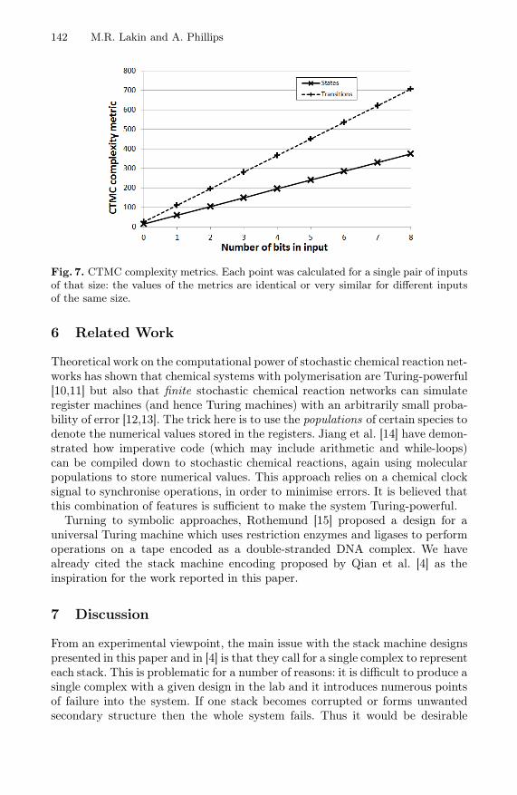
Finally, Figure 7 shows how the numbers of states and transitions in theCTMC scale with the initial number of bits in the inputs stacks A and B.Thanks to our reaction gate design we see linear increases in numbers of bothstates and transitions with increasing input size.
142 M.R. Lakin and A. Phillips
Fig. 7. CTMC complexity metrics. Each point was calculated for a single pair of inputsof that size: the values of the metrics are identical or very similar for different inputsof the same size.
6 Related Work
Theoretical work on the computational power of stochastic chemical reaction net-works has shown that chemical systems with polymerisation are Turing-powerful[10,11] but also that finite stochastic chemical reaction networks can simulateregister machines (and hence Turing machines) with an arbitrarily small proba-bility of error [12,13]. The trick here is to use the populations of certain species todenote the numerical values stored in the registers. Jiang et al. [14] have demon-strated how imperative code (which may include arithmetic and while-loops)can be compiled down to stochastic chemical reactions, again using molecularpopulations to store numerical values. This approach relies on a chemical clocksignal to synchronise operations, in order to minimise errors. It is believed thatthis combination of features is sufficient to make the system Turing-powerful.
Turning to symbolic approaches, Rothemund [15] proposed a design for auniversal Turing machine which uses restriction enzymes and ligases to performoperations on a tape encoded as a double-stranded DNA complex. We havealready cited the stack machine encoding proposed by Qian et al. [4] as theinspiration for the work reported in this paper.
7 Discussion
From an experimental viewpoint, the main issue with the stack machine designspresented in this paper and in [4] is that they call for a single complex to representeach stack. This is problematic for a number of reasons: it is difficult to produce asingle complex with a given design in the lab and it introduces numerous pointsof failure into the system. If one stack becomes corrupted or forms unwantedsecondary structure then the whole system fails. Thus it would be desirable
Modelling, Simulating and Verifying 143
to invent an alternative stack machine design in which there are many copies ofeach stack complex (and many copies of the state strand) and the updates to thestacks are synchronised, for example using a clock signal such as that proposedin [14]. This would probably require a different scheme for representing stacks,because the reversible stack manipulation primitives used above, and in [4],mean that stack operations could be undone before the synchronisation actuallyoccurs.
We noted in Section 5.1 that increasing the initial populations of fuels, inorder to enable long-running computations, can have adverse effects on the sim-ulation kinetics. In the model this can be addressed by using the constantkeyword of the DSD language to specify that the populations of certain species(such as fuels) should be fixed throughout the simulation. In practice, a morecomplex experimental setup would be required in which the population of fuelscan be replenished, either continually or at regular intervals. In principle, con-stant replenishment of DNA fuel should allow long-running, or even unbounded,computations (assuming that all computation steps are error-free).
In Section 5.2 we used model checking to provide some formal verification thatour stack machine examples work as expected. We were able to demonstrate somescalability by similarly verifying the result of adding a pair of eight-bit inputs.As shown in Figure 7, the size of the CTMC for our stack machine programsvaries linearly with the sizes of the inputs. This was a key goal which motivatedvarious design choices, such as the use of private history domains on the singlestrands which denote the current state of the machine. In general, however, thebrute force approach to model checking does not scale to large systems withmany different species and large populations. It may be possible to exploit workon modular model checking [16] to avoid this problem.
Another limitation of model checking is that it only verifies properties of thecollection of starting species. We were able to verify that all 2-bit inputs aresummed correctly, but we cannot derive a proof that the ripple carry adderworks correctly for all input sizes. We would probably need to use an interactivetheorem prover to prove such results mechanically. This would require formalis-ing the DSD language in said theorem prover, which could be a valuable exercisein itself.
Acknowledgements. We thank Dave Parker for help using PRISM, and ErikWinfree and Lulu Qian for useful discussions on the stack machine design from [4].
References
1. Venkataraman, S., Dirks, R.M., Ueda, C.T., Pierce, N.A.: Selective cell death medi-ated by small conditional RNAs. Proc. Natl. Acad. Sci. U S A 107(39), 16777–16782(2010)
2. Turing, A.M.: On computable numbers, with an application to the Entschei-dungsproblem. Proc. London Mathematical Society s2-42(1), 230–265 (1937)
3. Zhang, D.Y., Seelig, G.: Dynamic DNA nanotechnology using strand-displacementreactions. Nat. Chem. 3, 103–113 (2011)
144 M.R. Lakin and A. Phillips
4. Qian, L., Soloveichik, D., Winfree, E.: Efficient turing-universal computation withDNA polymers. In: Sakakibara, Y., Mi, Y. (eds.) DNA 16 2010. LNCS, vol. 6518,pp. 123–140. Springer, Heidelberg (2011)
5. Phillips, A., Cardelli, L.: A programming language for composable DNA circuits.J. R. Soc. Interface 6(suppl 4), S419–S436 (2009)
6. Paulevé, L., Youssef, S., Lakin, M.R., Phillips, A.: A generic abstract machine forstochastic process calculi. In: Proc. CMSB 2010, pp. 43–54. ACM, New York (2010)
7. Zhang, D.Y.: Towards domain-based sequence design for DNA strand displacementreactions. In: Sakakibara, Y., Mi, Y. (eds.) DNA 16 2010. LNCS, vol. 6518, pp.162–175. Springer, Heidelberg (2011)
8. Gillespie, D.T.: Exact stochastic simulation of coupled chemical reactions. J. Phys.Chem. 115, 1716–1733 (2001)
9. Hinton, A., Kwiatkowska, M., Norman, G., Parker, D.: PRISM: A tool for auto-matic verification of probabilistic systems. In: Hermanns, H., Palsberg, J. (eds.)TACAS 2006. LNCS, vol. 3920, pp. 441–444. Springer, Heidelberg (2006)
10. Bennett, C.H.: The thermodynamics of computation—a review. Int. J. Theor.Phys. 21(12), 905–939 (1982)
11. Cardelli, L., Zavattaro, G.: Turing universality of the biochemical ground form.Math. Struct. Comp. Sci. 20(1), 45–73 (2010)
12. Soloveichik, D., Cook, M., Winfree, E., Bruck, J.: Computation with finite stochas-tic chemical reaction networks. Nat. Comput. 7, 615–633 (2008)
13. Cook, M., Soloveichik, D., Winfree, E., Bruck, J.: Programmability of chemicalreaction networks. In: Condon, A., Harel, D., Kok, J.N., Salomaa, A., Winfree, E.(eds.) Algorithmic Bioprocesses, pp. 543–584. Springer, Heidelberg (2009)
14. Jiang, H., Riedel, M.D., Parhi, K.K.: Synchronous sequential computation withmolecular reactions. In: Design Automation Conference, San Diego, California,USA, June 5–10 (2011)
15. Rothemund, P.W.K.: A DNA and restriction enzyme implementation of Turingmachines. In: Lipton, R.J., Baum, E.B. (eds.) DNA Based Computers: DIMACSWorkshop, held April 4, pp. 75–120. American Mathematical Society, Providence(1996)
16. Kupferman, O., Vardi, M.Y.: An automata-theoretic approach to modular modelchecking. ACM T. Progr. Lang. Sys. 22(1), 87–128 (2000)