Zgoubi day 2009 David Kelliher ASTeC/RAL/STFC UKNF WP1 09/12/09.
date post
19-Dec-2015Category
view
216download
2
Modelling shock in solid targets
Goran Skoro
(UKNF Collaboration, University of Sheffield)
NuFact 06
UC Irvine, August 24-30, 2006
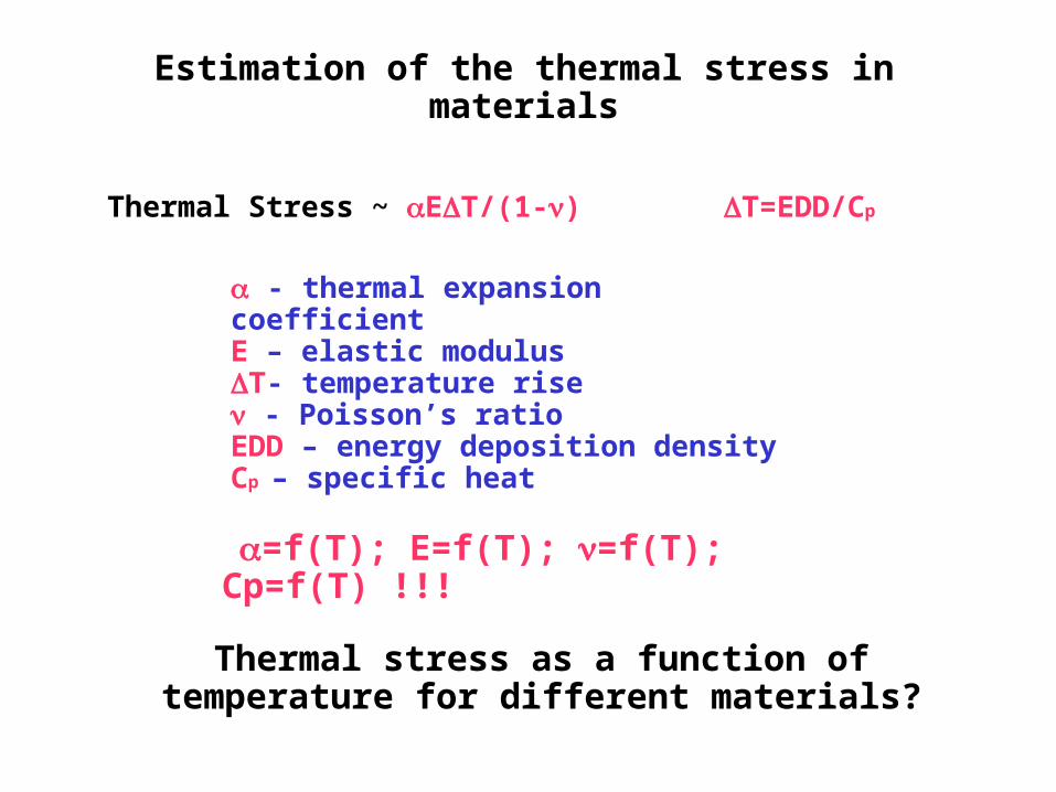
Thermal Stress ~ ET/(1-)
strain
T=EDD/Cp
- thermal expansion coefficientE – elastic modulusT- temperature rise - Poisson’s ratioEDD – energy deposition densityCp – specific heat
=f(T); E=f(T); =f(T); Cp=f(T) !!!
Thermal stress as a function of temperature for different materials?
Estimation of the thermal stress in materials

20 J/g corresponds to ~ 300 J/cc in Ta (and W)- energy density for 4-5 MW beam power, 6-10 GeV
protons -
High temperature target candidates: Ta, W, Nb(?), Mo(?)…

Assuming that the tensile strength (=f(T)) is a measure of
material mechanical strength we can introduce ‘stress quality’ factor = thermal stress/tensile
strengthlower value of stress quality factor -> ‘better’ candidate for solid target
W looks better than Ta
NB.Inconclusive strength data for Molybdenum. Looks interesting in general (it is valuable alloying agent). Almost all ultra-high strength steels contain Mo in amounts from 0.25 to 8% .
Graphite is ‘special’
(T2K)

LS-DYNA
supported
longitudinal
radial
Beam energy [GeV]
Peak
Str
ess
[M
Pa]
Von MisesStress in 2cm diameter, 66cm
long graphite target beam power: 4 MW, 50 Hz;
energy deposition from MARS;4x2ns bunches per pulse; 10 s macro-pulse length.
Stress in graphite target
Stress is not the main problem for graphite target!

2cm
20cm
• The target material exposed to the beam will be ~ 20cm long and ~2cm in diameter (in tantalum case).
•Energy density per pulse ~ 300 J/cc.
•Rotating toroidal ring (operating at ~2000 K);
• Individual bars...
•Cooling: radiation
•The target is bombarded at up 50 Hz by a proton beam consisting of ~1ns long bunches in a pulse of a few micro-s length.
micro-pulse
macro-pulse
Beam: protons, 3 – 30 GeV
High temperature candidates:TANTALUM, TUNGSTEN, ...
Simulations of the shock in the solid Neutrino Factory target
ISS baseline (April 2006):4 MW, 10 GeV, 50 Hz,
4 bunches per pulse, 2 ns rms.

Energy deposition in solid target
Temperature rise in solid target
High energy particle cascade calculations (MARS)
Input for thermal stress calculations (LS-DYNA)
Here: TANTALUM, Beam power = 5 MW, repetition rate = 50
Hz
Simulations... as realistic as possible

LS-DYNA simulations
Material model used in the analysis
•Temperature Dependent Bilinear Isotropic Model
•Uses 2 slopes (elastic, plastic) for representing of the stress-strain curve
• Inputs: density, Young's modulus, CTE, Poisson's ratio, yield stress, ...
“Theory”
LS-DYNA input (estimate; especially for T> 1000K)
strain
str
ess
[MP
a]
• reliable data can be found for temperatures up to 1000K (but inconclusive);
•no data (practically) at high temperatures.
Problems with material data:

LS-DYNA simulations (TANTALUM)
micro-pulse
macro-pulse
radial characteristic timelongitudinal characteristic
time
characteristic time (shock transit time)
=characteristic
length /speed of sound in
material
optimal macro-pulse length (topt)
topt
factor of 2 difference in shock
magnitude
(let's say) from 10 to 30 s

“Proof”: T2K target results
Slicing of the target does not help if shock transit time is bigger than macro-pulse length
• Graphite Bar Target : r=15mm, L=900mm (2 interaction length)
– Energy deposit … Total: 58kJ/spill, Max:186J/g T 200K
MARSJ/g Distribution of the energy deposit in the target (w/ 1 spill)
cm
macro-pulse length = 5 s
characteristic time (radial) = 10 s
beam
length = 90 cm
length = 1.5 cm
length = 0.3 cm

Peak stress as a function of beam energy
(normalized on mean energy density)
for fixed beam power (5 MW)
andrepetition rate (50
Hz)
for 2 different macro-pulse lengths
(3 s) and (10 s)
micro-pulse
macro-pulse
LS-DYNA simulations (TANTALUM)

measure of 'concentration' of deposited energy
Stress per deposited power- at the level of 250 MPa per MW -
'mean peak value' = averaged peak (von
Mises) stress across the target
LS-DYNA simulations (TANTALUM)
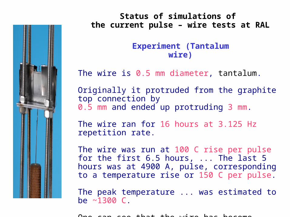
Experiment (Tantalum wire)
The wire is 0.5 mm diameter, tantalum.
Originally it protruded from the graphite top connection by 0.5 mm and ended up protruding 3 mm.
The wire ran for 16 hours at 3.125 Hz repetition rate.
The wire was run at 100 C rise per pulse for the first 6.5 hours, ... The last 5 hours was at 4900 A, pulse, corresponding to a temperature rise or 150 C per pulse.
The peak temperature ... was estimated to be ~1300 C.
One can see that the wire has become reduced in radius in parts and is thicker in others.
Status of simulations of the current pulse – wire tests at RAL

LS-DYNA simulations
Loads• Current pulse: ~ 5 kA, exponential
rise
strain
Time, 100 ns intervals
Rise time: ~100 ns
Flat Top: ~500 ns
30 ns risetime fitted to the waveform
• Energy density;temperature rise across the wire
• Lorentz force induced pressure wave
Geometry
• 0.5mm diameter; 40mm long wire; supported at bottom, free at top

LS-DYNA simulations
Multiple pulses
•Pulse time (heating) ~ 600 ns; temperature rise per pulse ~ 110 C
strain
T=300K
•Time between pulses (cooling) ~ 300 ms; LS-DYNA needs 115 h to complete 1 pulse!
•APPROXIMATION: Time between pulses (cooling)~ 500 s; 50x longer than (longitudinal) characteristic time!
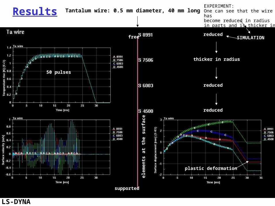
•50 pulses (16 h to complete);
• temperature rise ~ 1300 C
final cooling
↔ 500x longer time than (longitudinal) characteristic time.

LS-DYNA
supported
ele
men
ts a
t th
e c
en
trelin
e
50 pulses
plastic deformation
free
Tantalum wire: 0.5 mm diameter, 40 mm longResults
EXPERIMENT:Originally it protruded from the graphite top connection by 0.5 mm and ended up protruding 3 mm.
Simulation: 0.5 mm
supported
ele
men
ts a
t th
e s
urf
ace
50 pulses
free
plastic deformation
thicker in radius
reduced
reduced
reduced
LS-DYNA
Tantalum wire: 0.5 mm diameter, 40 mm longResultsEXPERIMENT:One can see that the wire has become reduced in radius in parts and is thicker in others.
SIMULATION
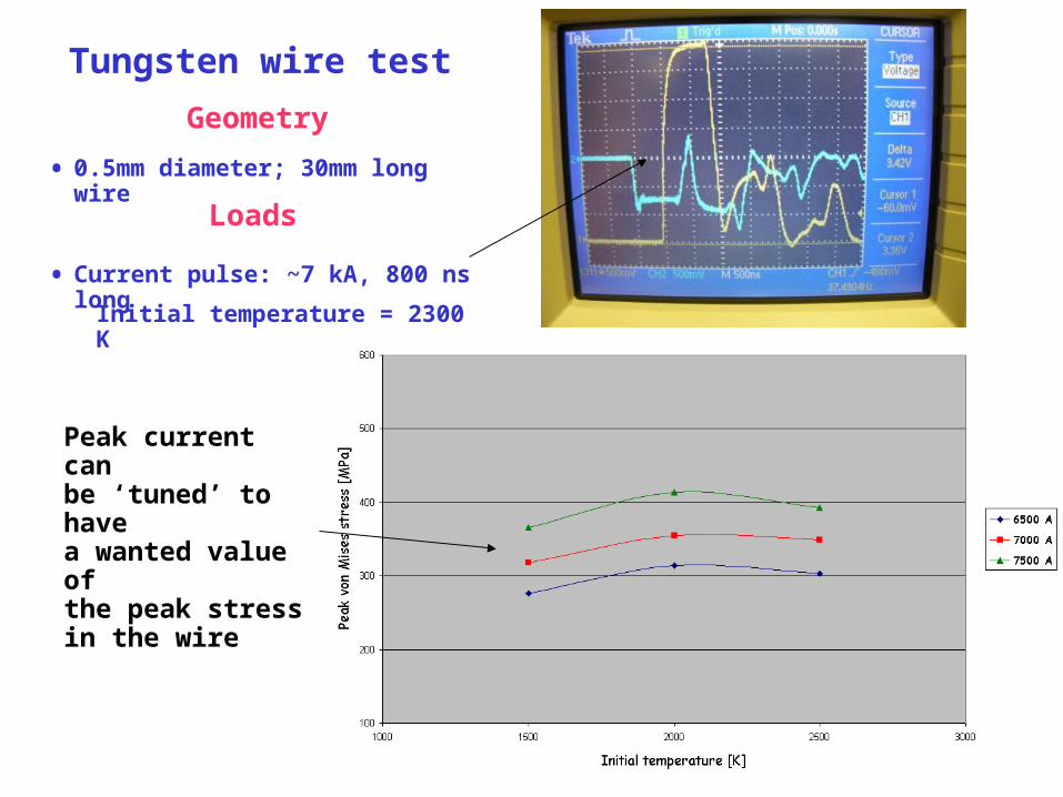
Loads
• Current pulse: ~7 kA, 800 ns long
Geometry
• 0.5mm diameter; 30mm long wire
Initial temperature = 2300 K
Tungsten wire test
Peak current can be ‘tuned’ to have a wanted value of the peak stress in the wire

LS-DYNA
supported
Stress in 2 x 17 cm tungsten target
(4 MW, 50 Hz, 6 GeV)
Macro pulse length [s]
Peak
Von M
ises
Str
ess
[M
Pa]
Comparison: Stress in real target vs. stress in tungsten wire
Stress in tungsten wire (7.5 kA, 800 ns long pulse)
Test result(7.5 kA, 800 ns long
pulse)
Tungsten wire (after a few minutes at 7.2 kA)

supportedS. Brooks
Stress in tungsten wire (5 kA, 800 ns long pulse)
Stress in 3 x 20 cm tungsten target (4 MW)
“Stress in 2 x 17 cm tungsten target” (2 MW)
This wire had survived over 3 million pulses at 5 kA.Bent into this severe shape
within a few minutes at 7.2 kA.
Solution: bigger target radius?It looks possible.
Captured yield practically the samefor 1 cm radius -> 1.5 cm radius.
Comparison: Stress in real target vs. stress in tungsten wire

LS-DYNA (3D)
“Additional” stress in the target: for example when beam is not at
a target axis (target bending, etc…)
TUNGSTEN targetoperating at 2000 K
4x2ns long bunches in a 10 s long pulse
Power = 4 MW, repetition rate = 50 Hz,Beam energy = 6 GeV (parabolic
distribution)
Energy deposition from MARS (S. Brooks)
Peak
Von M
ises
Str
ess
[M
Pa]
2 x 17 cm Tungsten targetBeam radius = Rod radius = 1 cm
3 x 20 cm Tungsten targetBeam radius = Rod radius = 1.5 cm
Beam offset [in rod radius units]
33 MPa; ~10% rise
46 MPa; ~33% rise

LS-DYNA (3D)
Beam radius = rod radius;Beam offset = 1/2 radius.
Peak Stress = 182 MPa
Peak Stress = 170 MPa
Peak Stress = 175 MPa
beam
beam
beam
Tungsten target: 3x20 cmBeam: 4 MW, 50 Hz, 6 GeV, 4x2ns, 10 s
(1)
(2)
(3)
Energy deposition from MARS (S. Brooks)
(1)
(2)
(3)
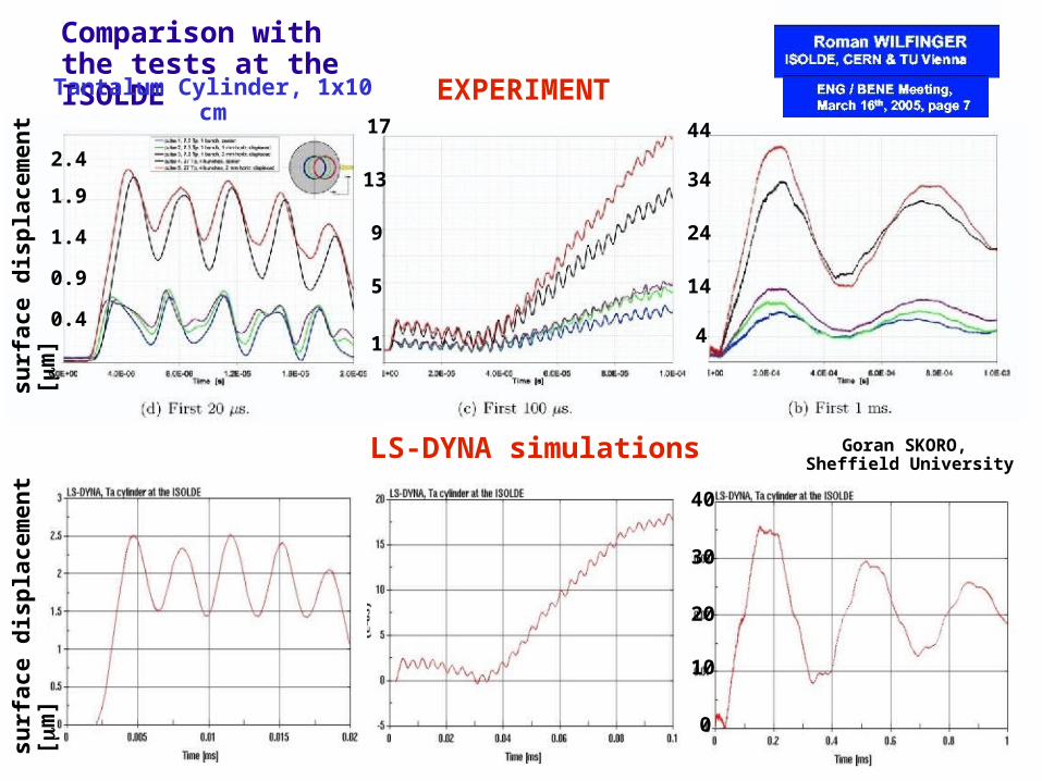
Comparison with the tests at the ISOLDE
0.9
Tantalum Cylinder, 1x10 cm
EXPERIMENT
1.9
0.4
1.4
2.4
1
5
9
13
17 44
24
34
14
4
Goran SKORO, Sheffield University
40
30
20
10
0
LS-DYNA simulations
su
rface d
isp
lacem
en
t [
m]
su
rface d
isp
lacem
en
t [
m]
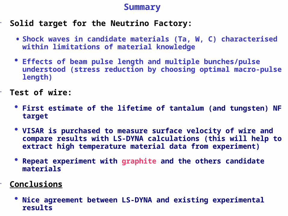
Summary
• Solid target for the Neutrino Factory:
• Shock waves in candidate materials (Ta, W, C) characterised within limitations of material knowledge
• Effects of beam pulse length and multiple bunches/pulse understood (stress reduction by choosing optimal macro-pulse length)
• Test of wire:
• First estimate of the lifetime of tantalum (and tungsten) NF target
• VISAR is purchased to measure surface velocity of wire and compare results with LS-DYNA calculations (this will help to extract high temperature material data from experiment)
• Repeat experiment with graphite and the others candidate materials
• Conclusions
• Nice agreement between LS-DYNA and existing experimental results
• 2 MW -> looks possible in 2 cm diameter target (W is better than Ta)
• 4 MW -> needs bigger target diameter (2 cm -> 3 cm)