Modelling Parallel Programs and Multiprocessor ... · PDF fileNASA Contractor Report 177582...
44
NASA Contractor Report 177582 Modelling Parallel Programs and Multiprocessor Architectures with AXE Jerry C. Yan and Charles E. Fineman (NASA-C_-I77592) MODELLING PARALLEL P_GGRAM_ ANO MULT[P.ROCE_SOR ARCH[TECTURFS WITH _XF (_Cer]in_ Feder_] Systems) 40 p CSCL 09_ G_/b2 Ngi-24793 Unc1Js 0015Z70 Contract Number NAS2-13210 May 1991 National Aeronautics and Space Administration https://ntrs.nasa.gov/search.jsp?R=19910015479 2018-05-19T16:30:28+00:00Z
Transcript of Modelling Parallel Programs and Multiprocessor ... · PDF fileNASA Contractor Report 177582...

NASA Contractor Report 177582
Modelling Parallel Programs andMultiprocessor Architectures with AXE
Jerry C. Yan and Charles E. Fineman
(NASA-C_-I77592) MODELLING PARALLEL
P_GGRAM_ ANO MULT[P.ROCE_SOR ARCH[TECTURFS
WITH _XF (_Cer]in_ Feder_] Systems) 40 p
CSCL 09_
G_/b2
Ngi-24793
Unc1Js
0015Z70
Contract Number NAS2-13210May 1991
National Aeronautics andSpace Administration
https://ntrs.nasa.gov/search.jsp?R=19910015479 2018-05-19T16:30:28+00:00Z

J

NASA Contractor Report 177582
Modelling Parallel Programs andMultiprocessor Architectures with AXE
Jerry C. Yan and Charles E. Fineman
Sterling Federal Systems, Inc.1 121 San Antonio Road
Palo Alto, CA 94303
Prepared forAmes Research CenterContract Number NAS2-13210
May 1991
National Aeronautics andSpace Administration
Ames Research CenterMoffett Fielcl,California 94035-1000
_J

Table of Contents
Summary ................................... •.............. 1
1. Introduction ............................................................................................................................ 2
1.1. Background ................................................................................................................... 2
1.2. Software Architecture Overview ................................................................................... 2
1.2.1 The AXE Modelling Package ................................................................................. 3
1.2.2 The AXE Visualization Package ............................................................................. 4
1.2.3. AXE System Requirements ................................................................................. 4
1.3. Report Outline ........................................................................................................ 5
2. The AXE Visualization Package .............................................................................................. 5
2.1. Display Philosophy ....................................................................................................... 6
2.2. Panel Description ............................................................................................. 7
2.2.1 Multiprocessor Activity Panel ............................................................................ 7
2.2.2 System Load Panel and Global Traffic Panel ........................................................ 8
2.2.3 Site Load Distribution Panel .................................................................................. 8
2.2.4 Process Status Panel ............................................................................ 8
2.3. Controlling Instrumentation/Visualization ..................................................................... 11
2.3.1 Displaying Multiprocessors of Different Topologies ............................................ ! 1
2.3.2 Display oll Multiple Screens .................................................................................. 11
3. Multiprocessor Hardware Models .......................................................................................... 12
3.1. Functional Model of a Site ............................................................................................. 12
3.2. Building Multicomputer Models with User-Settable Parameters .................................. 12
3.2.1 Parameters Controlling Connection Topologies .................................................... 12
3.2.2 CPU and Routing Overhead .............................................................................. 13
3.3. Message Passing Protocols ........................................................................................... 13
3.4. "Diagonal-First" Store-and-forward Algorithm ........................................................... 15
PRECEDING PAGE
lll
BLANK NOT FILMED
\
3.5. Message Sending on Hypercube Models ...................................................................... 15
3.6. Message Sending on Token-Ring Models ..................................................................... 16
4. Parallel Software Models ........................................................................................................ 16
4.1. The Player's Programming Paradigm ......................................................................... 16
4.2. BDL -- A Behavior Description Language for Parallel Programs ................................ 18
4.2.1 Top-level Constructs .............................................................................................. 18
4.2.2 Player Creation ........................... . .......................................................................... 20
4.2.3 Data Manipulation ................................................................................................. 21
4.2.4 Message Passing ................................................................................................... 21
4.2.5 Flow Control ......................................................................................................... 23
4.2.6 Miscellaneous ........................................................................................................ 24
4.3. Building Abstract Software Models .............................................................................. 24
4.3.1 The N-body Problem ................................ , ............................................................ 25
4.3.2 Quicksort ............................................................................................................... 28
4.4. Summary ....................................................................................................................... 30
5. Conclusions and Future Research .......................................................................................... 31
Acknowledgements .................................................................................................................... 32
References .................................................................................................................................. 32
iv

Figures and Tables
Figure
Figure
Figure
Figure
Figure
Figure
Figure
Figure
Figure
Figure
Figure
Figure
Figure
Figure
Figure
Figure
Figure
Figure
1-1. Components of the Axe Experimentation Environment .................................... 3
2-1. Effect of Displayed Load Values Using Various Values of a and b .................. 6
2-2. Effect of a "Self-updating" Panel ...................................................................... 6
2-3. The Multiprocessor Activity Panel ..................................................................... 7
2-4. The System Load Panel and Global Traffic Panel .............................................. 8
2-5. The Site Load Distribution Panel ....................................................................... 8
2-6. The Process Status Panel .................................................................................... 9
2-7. State Transition for a Computing Process .......................................................... 9
2-8. Screen Layout for Grid Multiprocessors ............................................................ I0
2-9. Screen Layout for Distributed Systems on a Token-Ring .................................. 10
2-10. Multiple Screen Layout for Token-Ring Systems ............................................ 11
3-1. Message Passing on Multicomputer Models Simulated in Axe ........................ 14
4-1. A Simple Diagram of Players and Their Interactions ........................................ 18
4-2. BDL Schematic of a "Body" Player in the N-Body Problem ............................ 26
4-3. BDL Abstraction of a "Body" in the N-Body Problem ..................................... 27
4-4. BDL Specification of Quick-Sort ....................................................................... 28
4-5. BDL Abstraction of Quick-Sort ......................................................................... 29
4-6. Two BDL Models of a "File" Player ................................................................. 31
Table 3-1. Parameters Controlling Connection Topologies .................................................. 12
Table 3-2. Timing Parameters for Routing and Other Overhead .......................................... 13


Summary
AXE, An Experimentation Environment for Parallel Systems, was designed to facilitate research
for parallel systems at the "process level" using discrete-time simulation -- without resorting to
lengthy instruction-set level simulations or general stochastic models. It provides an integrated
environment for specifying computation models, multiprocessor architectures, simulation, data
collection and performance visualization. The user may study resource management strategies,
parallel problem formulation, alternate hardware architectures, and operating system algorithms.
AXE's simple, structured user-interface enables the user to model parallel programs]machines
precisely and efficiently. Its quick turn-around time keeps the user interested and productive. The
user can also observe the simulation on the color screen via four major panels:
• the Muhiprocessor Activity Panel displays CPU bottlenecks and message routing;
• the System Load Panel illustrates the overall utilization of processing sites in the system;
• the Global Traffic Panel monitors the amount of inter-site communication; and
• the Process Status Panel traces the dynamic status of the software.
AXE models multiprocessors as a collection of sites. A site represents various operating system
functions available for management and execution of the computation. The user may easily
modify various architectural parameters of the multiprocessor such as the number of sites,
connection topologies, routing algorithms, communication link bandwidfl_s, and various CPU
overhead for operating system activities.
Parallel computations in AXE are represented as collections of autonomous computing objects
known as players. Players may be created either at compile-time or run-time. Each player is an
instantiation of a specific player type. There are no shared data structures. Messages are
exchanged asynchronously. A player may block to accept only messages of a specific O,pe (while
others queue up temporarily). Players may be used to represent parallel code-bodies (e.g.
fork/join), communicating processes, Halstead'sfutures, remote procedures, and a subset of
Hewitt's actors. A BEHAVIOR DESCRIPTION LANGUAGE (BDL) is used to specify such models.
BDL program models preserve the interaction patterns between players and their processing
requirements.
The AXE software package is being used at NASA Ames Research Center for research and
development activities in high performance computing.

1. Introduction
1.1. Background
Realistic evaluation of new multiprocessor architectures and the accompanying resource
management tools depends on the study of real applications on actual multiprocessor prototypes.
I towever, the development of complete language and compiler tools, together with run-time
environments is currently prohibitive for short term use in research. Therefore, An
Ex__erimentation Environment, AXE, was designed to facilitate such investigations at the "process
level" using discrete-time simulation -- without the need to resort to lengthy instruction-set level
simulations or general stochastic models.
Researchers at Ames Research Center are using AXE to study dynamic load-balancing strategies
for highly parallel systems [i]. It provides an integrated environment for computation model
specification (using BDL), multiprocessor architecture specification, simulation, automated data
collection and performance visualization. The researcher is able to study resource management
strategies, parallel problem formulation, alternate hardware architectures, and operating system
algorithms: -AXE i_s!nlple, structured user-interface enables the experinaenter to model different
parallel programs and define various machines precisely and efficiently. Its quick turn-around
time for experiments keeps the researcher interested and productive.
1.2. Software Architecture Overview
Three disciplines were observed when designing AXE !
i i structured user-interface enabling the researcher to model different parallel programs
and machines precisely and efficiently;
2. quick turn-around time for experiments -- keeping the researcher interesied and
productive;
3. minimized need for re-compilation -- AXE is structured so that a maximum number of
parameters may be modified without needing re-compilation. These include machine
characteristics, operating system parameters, input data, simulation data collection methods
as well as the selection of heuristics for studying resource management strategies.
2

As shownin Figure1-1,AXEis madeupof two majorcomponents,theModelling Package and
the Visualization Package. The six components that make up both packages will be discussed in
the next sections.
AXE Modelling Package
Behavior Description
Language (BDL)
AXE/CSIM
Instrumentation
Options
AXE Visualization Package
• [ "Application Specific
1 Performances,. Display Panels 6
/ System Performance
Statistics Display2 Panels 5
,._ Activity & Status3 r Display Panels 4
t* • _a
Figure 1-1. Components of the AXE Experimentation Environment
1.2.1 The AXE Modelling Package
The AXE Modelling Package facilitates specification of parallel hardware and software models as
well as simulation of their interactions. This package is made up of three basic software
components as shown in Figure 1-1:
1. BEHAVIOR DESCRIPTION LANGUAGE (BDL) TRANSLATOR: Models of parallel
computations are specified in AXE using BDL. The BDL translator, implemented as a
separate front-end to AXE, converts BDL models into forms understood by other AXE
modules. BDL follows an object-oriented LISP-like syntax. A parallel application may be
specified using players that interact with one another via message passing. This
communicating players paradigm gives the user a powerful and flexible tool for generating
parallel application models whose performance is to be analyzed by AXE.
2. AXE/CSIM SIMULATOR: AXE/CSIM is a discrete-time event-driven simulator based on
CSIM [2]. AXE/CSIM simulates the execution BDL program models on a variety of
multiprocessor architectures. The performance behavior of various BDL program models
running on various nmltiprocessor architectures may then be predicted and analyzed.
3. INSTRUMENTATION OPTIONS: The user may be interested in a variety of performance
data which encompass application-specific issues, overall performance predication, load
balancing information and many other perfomaance issues. The Instrumentation Options
component of AXE allows the user to define and generate the desired performance data sets
to his/her particular interests.

1.2.2 The AXE Visualization Package
Thedatageneratedby thesimulationsbytheModelling Package are of little use unless the user
has a clear and efficient means of displaying it. The AXE Visualization Package provides a flexible
set of performance data analysis and representation tools. As shown in Figure 1-1, the Visualiza-
tion Package may be classified into three major components.
4. ACTIVITY AND STATUS DISPLAY PANELS animate various performance parameters of the
system during simulation. These displays can be used to examine the state of each
processor and its interaction with other processors at every instant of the simulation. These
"instantaneous" displays can be Very Useful in finding particular System bottlenecks.
5. SYSTEM PERFORMANCE STATISTICS DISPLAY PANELS plot the variation of performance
parameters and statistics over a specified period of time. With these display panels, the
user may identify the overall performance of the specified model. In addition, this class of
display panels can be very helpful in identifying the various phase and state changes that
may occur in the modelled system over timel Instead of having to monitor an animation of
the system running over a long period moment-by-moment, the modeler may quickly
recognize trends or patterns of performance that occur over time.
6. APPLICATION SPECIFIC DISPLAY PANELS: When evaluating a modelled system, it is
often useful to correlate the system performance data with the behavior of the application
that is causing the performance behavior. For this reason, the AXE Visualization Package
allows the user to create display panels that are application specific.
1.2.3. AXE System Requirements
Portability has been a major consideration in the design and implementation of AXE. The
workstation requirements for successful execution of AXE are as follows:
AXE Modelling Package runs on any hardware platform that CSIM executes (See [3]). These
include Sun3, Sun4, SunSparc, DecStation 3100 and 5000, Sequent, VAXen etc.
AXE Visualization Package runs on workstation environments on which X-Windows
(X11R4) are mounted. Examples include SGI, Sun3, Sun4, SunSparc, DecStation 3100
and 5000.
It should be noted that event trace files that are output by the AXE Modelling Package can become
quite large. The user should take this consideration into account before attempting to run large
complex models.
4

1.3. Report Outline
Chapter2 describestheAXE Performance Visualization Package. Both hardware and software
status are monitored. Examples of monitored parameters/activities include changing ready-queue
lengths, message sending, cpu load distribution, and whether players are active, blocked, or idle.
There are six major panels that can be displayed on one or two color displays. The user can pause
during the playback of the simulation and reconfigure the screen to permit detailed observation of
the activities displayed in any particular panel.
Chapter 3 describes how parallel architectures are modelled in AXE. Basically, AXE models
multiprocessors as a collection of predefined sites. Machine topology and system overhead may
be tailored further by the user parametrically. A discrete-time event-driven simulator based on
CSIM is responsible for simulating the execution of BDL program models on these multiprocessor
models.
Chapter 4 describes how parallel software is modelled in AXE. A parallel computation is rep-
resented as a collection of autonomous computing processes (or objects) known as players.
Messages are exchanged asynchronously between players. A BEHAVIOR DESCRIPTION
LANGUAGE (BDL) used to specify the behavior of players is also described. Two examples in-
volving the building of abstract execution models for parallel programs are then given.
Chapter 5 summarized the work presented here and gives directions for future research and
development.
2. The AXE Visualization Package
The use of color graphics to represent parallel program execution on multicomputers has been
researched elsewhere to help interpret parallel system performance (4] as well as alternative
architectures for executing parallel knowledge-based systems [5]. The monitoring facilities in AXE
were designed primarily to display resource utilization in multicomputers and help locate software
bottlenecks for player programs.
When compiled with the proper switches (see [6]), AXE will create a trace file containing events
generated during a run. This event file is used to drive the AXE Visualization Package described in
this section. Both hardware and software status are monitored. Examples of monitored
parameters/activities include changing ready-queue lengths, message sending, player creation/
temfination, and whether players are active, blocked, running or idle. There are six major panels

thatcanbedisplayedononeor two colorscreens.Theusercanpauseduringtheplaybackof the
simulationandreconfigurethescreento permitdetailedobservationof theactivitiesdisplayedin
anyparticularpanel.
2.1. Display Philosophy
1 IL
q_0.75.
"_ 0.5'
0.25.
1
Actual ready-queue length NA
.......... :, +:+:+::::
iiiii_i_i_i_i_i_i_:_i!i!i!i!i!iiiiiiiiii_i_!_i_i_iii_i_iiiiiiii!!iiiiiiii!_ii!i!iii!iiiiiiiiii
i!iiiii!?iliiiiiiii_ ii!iiiii!iiii_iiiii'!i!ii!ii!ii!!i!!i
ii!ii!ii! ii!!i!i!;
_"_ !!ii_iiiii_iiii!_ii_i)i!i!iii_ii!ii:i_!_i_i_i_!_!_!_!_i_!i!i!i!i!i!i!?!i!;ii_iii!iiiiiiiiiiiil
iii!i_i!ii!ili!iii!_..................ii!iiiiiii!iiiii_i_ii_!ili!i!ii!!:i_!_
A A
.:.:.:.:,:,:,:,:.:
:i:!:)i:i:i:i:i:i......... i:iii:!!ii_!!!!!_!
2 3 4 5 6 7 8 9 10
ii_i!ili_i!i!i_i!!ii_:+:,:+:+:+::.:,:+:L:.:.:.:+:.:-:,:,:-:,::+:
v iiiiiiiii i!iiiiiiii !ilili!iiiiiiiiiiii!!i!iiiiiiiiiiiiiiiii
:.:+:+:+:+:.
i
11 i2
[] a=l.0;b=0.0
-" a = 0.5; b = 0.5
,u a = 0.2; b = 0,8
Simulation Time
Figure 2-1. Effect of Displayed Load Values Using Various Values of a and b
Before discussing what the color bars that change heights mean in each panel, the relationship
between the actual color (and height) observed and the actual parameter value are presented here.
Instead of using the instantaneous lengths of the ready-queue and message queues directly, a
moving-average function is used with the AXE Visualization Package. Suppose that the length of
the ready2queue (at some site) at time "c is 3.'v if the display is to be updated at time "I:1, the
displayed queue-length is computed according to a._,rt + bX'r2 where X'r2 = the last displayed
value, a and b are non-negative constants and a + b = 1. The moving-average function is used to
filter out rapid varying load values so that the researcher can observe general trends in load
variation easily. As illustrated in Figure 2-1, in order to track the actual load more closely, higher
values should be chosen for a.
0.25 -
[] actual load
--. a = b = 0.5 (with update)
a = b = 0.5 (w/o update)
Simulation Time
Figure 2-2. Effect of a "Self-updating" Panel
6

BecauseAXEis anevent-drivensimulator,thepanelisupdated(bydefault)only everytimea
processis addedor removedfrom theready-queue.Unfortunately,whenaprocessis scheduledandexecutesfor a longtime,theloadvalueatthatsitewill neverreachtheactualvaluebecauseof
theeffectof themoving-averagefunction.Figure2-2illustratesthissituationwhentheloadof a
siteis changedfrom 0 to 1. Therefore,theACTIVITY AND STATUS DISPLAY PANELS are
designed so that each site updates its load value every now and then. This update interval is
settable by the user (see [6]).
2.2. Panel Description
2.2.1 Multiprocessor Activity Panel
The Multiprocessor Activity
Panel displays CPU usage and
message routing. As shown in
Figure 2-3, a multicomputer which
consists of 16 processing sites
connected as a 2-dimensional grid
is simulated. A line joining two
adjacent sites indicates that a mes-
sage is being transmitted between
them. A vertical color bar on the
left-hand-side of the panel
illustrates the color scheme used
-- light blue representing the
lowest load, through green, yellow
and red, to magenta as the highest.
Each site contains two color Figure 2-3. The Multiprocessor Activily Panel
columns. The one on the left-hand-side (called CPU load indicator) indicates how busy the CPU at
that site is by both changes in height and color. The one on the right hand-side (called router
processor load indicator) illustrates how busy the communication processor is using a similar
color scheme. Where the color of the CPU load indicator represents average length of ready-
queue, the color of the router processor load indicator indicates the average number of packets
waiting to be routed at each site. The relative width of CPU load indicator and the router
processor load indicator can be adjusted to display the distribution of CPU or traffic hot spots.
7

f
2.2.2 System Load Panel and Global Traffic Panel
The System Load Panel and Global Traffic Panel look very much alike as Figure 2-4. illustrates.
The System Load Panel displays the overall utilization of processing sites in the system. The
number of active sites is plotted against simulation time. The Global Traffic Panel, on the other
hand, monitors the amount of inter-site communication. The rate of messages sent across sites is
plotted against simulation time. Data of more than one simulation can be plotted on top of one
another. This feature is especially useful when comparing the performance of two mappings.
Simulation Time
Figure 2-4. The System Load Panel and Global Traffic Panel
2.2.3 Site Load Distribution Panel
The Site Load Distribution Panel plots the "loacF' of all the sites in ascending order. The load of
a site is the average ready-queue length for some user-settable time interval. Load distribution is
"even" if the curve resembles a "plateau" as shown in Figure 2-5a.
ution Panel
(a) "Closer-to Ideal" Distribution
i Site Load Distribution Panel
(b) Undesirable Distribution
Figure 2-5. The Site Load Distribution Panel
2.2.4 Process Status Panel
The Process Status Panel (Figure 2-6.) traces the dynamic status of the software. Like the multi-
processor activity panel, the 2-dimensional grid of sites is represented as an array of rectangles.

Inside each site are a number of smaller rectangles, each of which, in turn, is divided into two color
columns. The one on the left (called the "message queue-length indicator") indicates the number
of unprocessed messages queued up in the message buffer of that particular player. The one on
the right, called "player status indicator", represents the state each resident player is in:
Empty (1"']): no player
is instant!ated L Q.L. = 20 Process Status Panel
Yellow (_)i player is _ _ _ 1"_ _ _ I-_ 1"_
scheduled, ready to _ _ _ [-_ _ _ I-_
make use of (but have IT'] rl] [_ IT-] _ _ I-_
not got hold of) theffzlrvA
CPU (i.e. it is in the _ _ ['_ IT'] _ _ ['_
ready queue); ['l--] ['T"] ['l-'] IF] 1"71 IT-] _ ['[--]
Red (_): player gets
hold of the CPU and is _ _ I]-'] 1"_ r]_] I'_ _
executing (under the IT-] I-]--I IT'-I 1"_ _ 1"I-"] I-_ IT]
currently available
models, there will be _ _ _ _ _ _ ['_ I'_
at most one such _ _ _ _ _ _ I-_
Q.L.=0 [_ ["_ [_[_] [-_[_ _ IT--]player per site);
Blue (_): player isFigure 2-6. The Process Stalus Panel
blocked, waiting for activated
the arrival of a specific Scheduled _ _
message from another player gets I finishes _ Idle
hold _p
(e.g. the reply to a message it of CPU rocessing
sent earlier, the evaluation of a
future or the return of a _" message arrives_ Blocked
remote procedure call); Executing waits for message
Grey (_): otherwise, the
player is in a dormant or idle Figure 2-7. State Transition for a Computing Process
state, waiting to be activated by the ,arrival of a message.
In the case of Figure 2-6, up to 6 players can be monitored at each site. Figure 2-7. illustrates the
events that cause state transition for processes. The relative width of the message queue-length
indicator and the player status indicator can also be changed. Software bottlenecks can be l_ated
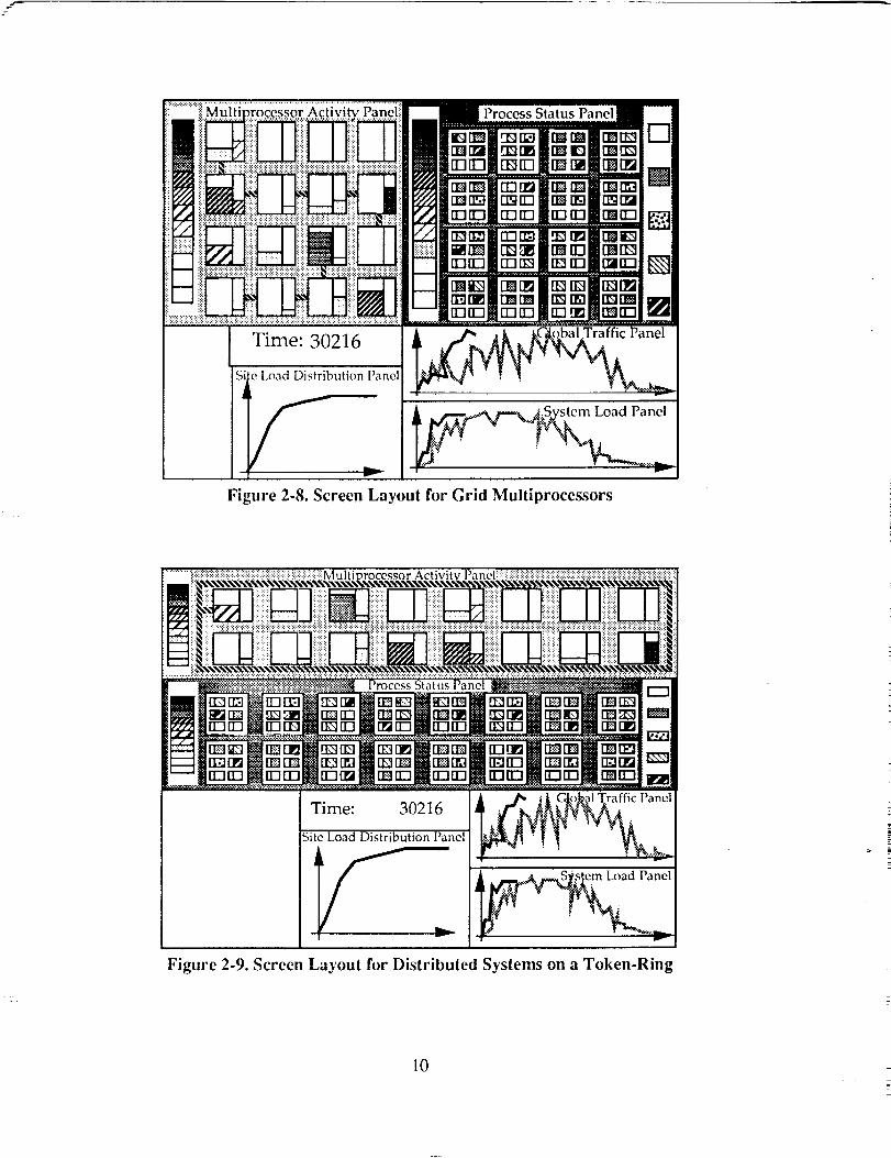
by spotting players with long message queues. Figures 2-8 on the next pate illustrates bow all the
above mentioned panels will fit together on a screen.
i!!!_!ii_i_iii_!]i_!i i i :::::
Time: 30216
Si e Load Distribution Panel
fFigure 2-8. Screen Layout for Grid Multiprocessors
_l l_i!i i ii:_ !ii: [_: ::ii _:i+::ii!i _i !iii!iii:[_i::iii::::i! _] ii!::ii]:i [:.:_
.....=..iiiii,:___:._G,,___if! ii_iiiii_i :!i!ii! r:.iiiiii:i ii!;iiii!i ilili!i!i i!!iiii_i:iiil ii:ii_
Time: 30216
)Site Load Distribution [ anel_fic Panel]
Figure 2-9. Screen Layout for Distributed Systems on a Token-Ring
10
2.3. Controlling Instrumentation/Visualization
2.3.1 Displaying Multiprocessors of Different Topologies
Depending on the topology of the simulated multiprocessor, the Multiprocessor Activity Panel
and Process Status Panel will be displayed differently. Figure 2-9 illustrates how a token-ring
connected multiprocessor will be displayed on the screen. The basic operations of the panels are
identical. A line segment joining a site and the ring indicates that site currently holds the token, and
is sending a packet out onto the ring.
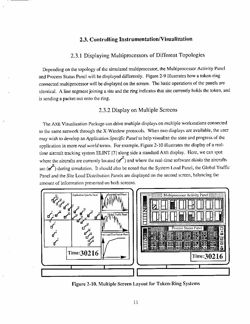
2.3.2 Display on Multiple Screens
The AXE Visualization Package can drive multiple displays on multiple workstations connected
to the same network through the X-Window protocols. When two displays are available, the user
may wish to develop an Application Specific Panel to help visualize the state and progress of the
application in more real world terms. For example, Figure 2-10 illustrates the display of a real-
time aircraft tracking system ELINT [7] along side a standard AXE display. Here, we can spot12
where the aircrafts are currently located (t:fr) and where the real-time software thinks the aircrafts
are (n/') during simulation. It should also be noted that the System Load Panel, the Global Traffic
Panel and the Site Load Distribution Panels are displayed on the second screen, balancing the
anaount of information presented on both screens.
7
tf-7
t(
Application Specific Panel
2
" 12 12
Time:30216
i _fIic Panel
w
Site l_'..ad Dis_'ibtalitm P_'_el
#r---
II
::::i::ii::i::::::::i::i::iii:::ii]:::::ii::::::::ii::iMultiprocessor Activity( Panel iiiii!i::i::iii::iiiiiiiii::iii::iiiii::i::iiii
It1 "l[_':":_?:>"'=:_ii:'.:::'_:'-':'2, ' ' Process. Stattlsl_cl r _'_.... i _....
?II rrrn _rm nnll _n
- " fii_iim©_"_m ©- [] "
Time:30216
I I
I
Figure 2-10. Multiple Screen Layout for Token-Ring Systems
11

3. Multiprocessor Hardware Models
3.1. Functional Model of a Site
AXE is designed to model multicomputers; they consist of homogeneous processing elements
(sites) connected in a nearest neighbor fashion by physical communication links. Each site is
autonomous -- with its own local memory, processor unit and an operating system kernel
governing message forwarding, task scheduling, as well as memory management. The local
memory of each site is assumed to be large enough to hold any number of players. CPU time is
allocated to players on a FIRST-COME-FIRST-SERVE basis (FCFS) by default at each site. If the
CPU is busy when a player makes a CPU request, the requesting player will be put on a ready-
queue until the CPU becomes available. Players may still be preempted by the mailer processes at
each site responsible for message routing. AXE also implements a ROUND-ROBIN scheduling
algorithm and allows more than one player at a site to process concurrently. The quantum size is
settable by the user but the simulator has to be recompiled.
3.2. Building Multicomputer Models with User-Settable Parameters
3,2.1 Parameters Controlling Connection Topologies
A "machine configuration file" defines the topology and size of the multicomputer to be
simulated. Changes to this file will only take effect when the simulator is recompiled. Table 3-1
summarizes how different multicomputers can be defined by setting constants to different values.
.... Topology
Token rin:g
Grid
I Iypercube
Number of sites
n, i . m i,
nx by ny
2 n
Constant Definitions
#define TOKNRINGI I I
#define GRID
#define DIM X n xw
#define DIM Y ny
#define NO OF SITE (n x * ny)
#define lPSC2
#define NO OF DIM n
#define NO OF SITE (2 n)
Table 3-1. Parameters Controlling Connection Topologies
12
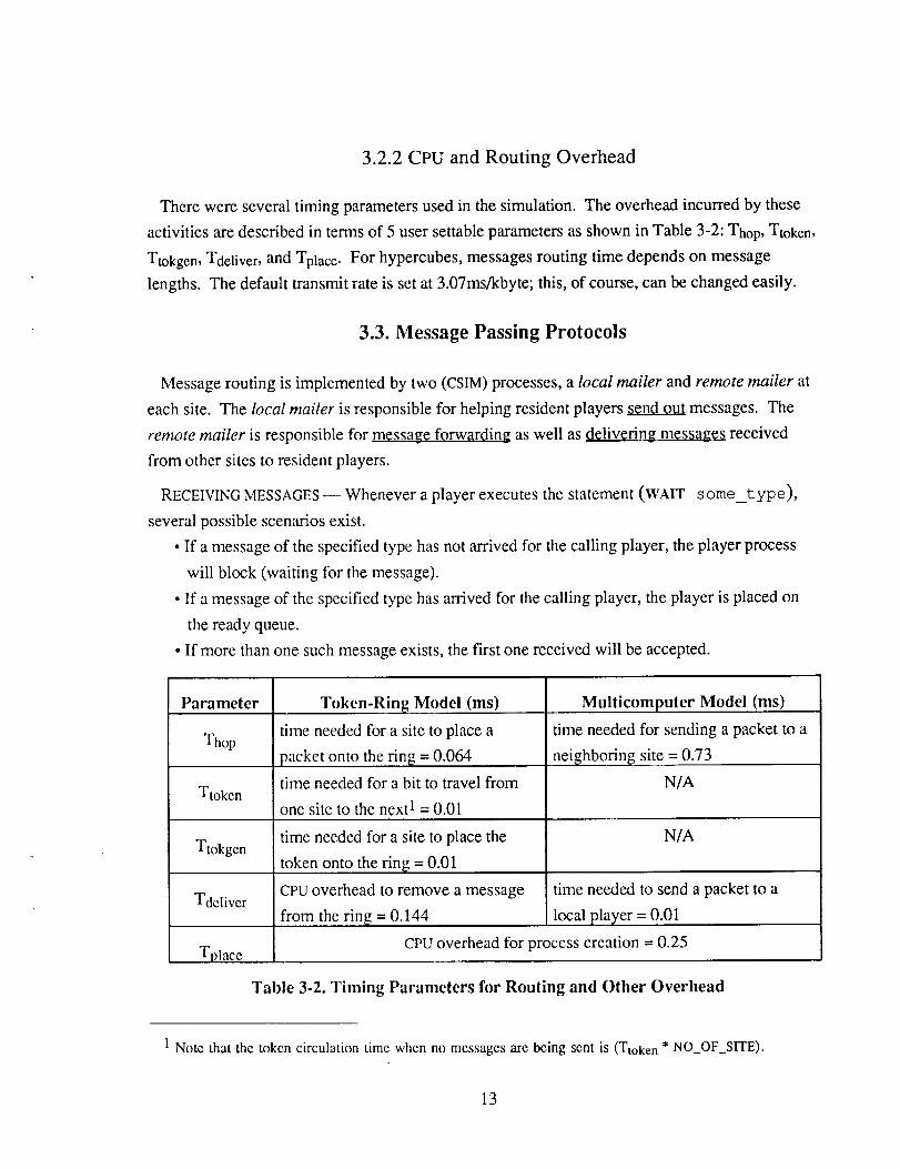
3.2.2 CPU and Routing Overhead
Therewereseveraltimingparametersusedin thesimulation.Theoverheadincurredby theseactivitiesaredescribedin termsof 5 usersettableparametersasshowninTable3-2:Thop,Ttoken,
Ttokgen,Tdeliver, and Tplace. For hypercubes, messages routing time depends on message
lengths. The default transmit rate is set at 3.07ms/kbyte; this, of course, can be changed easily.
3.3. Message Passing Protocols
Message routing is implemented by two (CSIM) processes, a local mailer and remote mailer at
each site. The local mailer is responsible for helping resident players send out messages. The
remote mailer is responsible for message fgrwarding as well as delivering messages received
from other sites to resident players.
RECEIVING MESSAGES--Whenever a player executes the statement (WAIT some_type),
several possible scenarios exist.
• If a message of the specified type has not arrived for the calling player, the player process
will block (waiting for the message).
• If a message of the specified type has arrived for the calling player, the player is placed on
the ready queue.
• If more than one such message exists, the first one received will be accepted.
Parameter
Thop
Ttoken
Ttokgen
Tdeliver
Tolace
Token-Ring Model (ms)
time needed for a site to place a
packet onto the ring = 0.064
time needed for a bit to travel from
one site to the next 1 = 0.01
time needed for a site to place the
token onto the ring = 0.01
CPU overhead to remove a message
from the ring = 0.144
Multicomputer Model (ms)
time needed for sending a packet to a
neighboring site = 0.73
N/A
N/A
time needed to send a packet to a
local player = 0.01
CpU overhead for process creation = 0.25
Table 3-2. Timing Parameters for Routing and Other Overhead
1 Note that the token circulation time when no messages are being sent is (Ttoken * NO OF SITE).
13

SENDING MESSAGES -- The local mailer at the sender site first decodes the mail-address of the
receiver to decide where it resides (i.e. locally in same site in which the sender resides or remotely
on a different site):
• If the receiving player resides locally (e.g. in Figure 3-1, player C at site 2 sends player D a
message at site 2) there are still three possible cases:
i) If the receiving player is either idle or blocked waiting for this message, the message
will be delivered by the local mailer and the receiver placed on the ready-queue.
ii) If the receiving player is running, the local mailer delivers the message to the player's
message buffer. When the player finishes processing, it will check this message buffer
and find the message.
iii) Otherwise, the receiving player is expecting another message (type); this message will
be put on the receiver's message buffer and the receiver remains blocked.
• If the receiving player resides in another site (e.g. in Figure 3-1, player A at site 1 sends
player D at site 2 a message): The local mailer decides that the receiver does not reside
locally (based on the receiver's mail-address) and delivers the message to the remote
mailer. The remote mailer then invokes a routing algorithm to determine the immediate
neighbor through which this message should be routed and sends the message to the
Nmote mailer at the selected n..eighbor. When the message finally arrives at the receiver
site, it is delivered directly (by the remote mailer of that site) to the receiving player.
_ 1Site-2
.............
,IHIl,l,l,,,lll,, ,I,III ,
Site-3
.......................II1"""_
Figure 3-1. Message Passing on Mullieomputer Models Simulated in AXE
FORWARDING MESSAGES -- The remote mailer is also responsible for forwarding messages
(e.g. in Figure 3-1, the remote mailer at site 2 forwards a message sent by player E at site 1 to
player B at site 3). The simplest class of routing strategies on multicomputers is known as store-
14
and-forward.Messageshop from site to site until they reach their destination. Routing target
selection may be static or dynamic. Dynamic routing algorithms select message routes based on
the (static) topology of the communication network as well as the amount of traffic in specific
parts of the system. AXE provides a variety of message forwarding schemes depending on the
chosen architecture. These schemes are described in the following sections.
3.4. "Diagonal-First" Store-and-forward Algorithm
A simple static diagonal routing strategy is used in AXE for an n-nary m-cube type connection
topologies (for a total of m n sites) to implement store-and-forward routing:
• The address of a site Sx is represented by an ordered m-tuple (Xl, x2 .... Xm) -- where 0 <
xi < n;
• Suppose a packet is to be sent from site Sxo, to sxd
- The address of the site of origin (Sxo) is represented as (Xol, Xo2, ... Xom).
- The address of the site of destination (sxd) is represented as (Xdl, Xd2 .... Xdm).
• Define a direction vector A = (xs1, x52 .... XSm) where xsi = Xdi - Xoi
• If Vi xsi = 0, then Sxo - sxd, i.e., the site of destination is the site of origin
• Otherwise, let t = position of max(Ix811, Ix821..... IxSml)
• if Xdt > Xot, then the neighbor site selected is (Xol ..... Xot+l .... Xom)
• if Xdt < Xot, then the neighbor site selected is (Xol ..... Xot- 1.... Xom)
3.5. Message Sending on Hypercube Models
Besides store and forward networks, users may choose to simulate their application using a
model based on the Intel iPSC/2 Hypercube. As part of this model, we have implemented a
version of worm-hole routing [8, 9]. The basic idea behind this type of routing is that a hardware
channel is set up between the two communicating sites that remains established until the entire
message get transmitted. Here is a scenario to illustrate what happens in the system when a
message is sent:
1. Source site (Ss) sends a request for connection (REQ) to destination site (Sd).
2. Intermediate sites receive REQ; routing logic decides who the next target site is and which
output channel to be used.
3. Allocate the output channel if it is free; otherwise, REQ is blocked inside the routing logic
until the required channel is available.
4. Sd receives the REQ and sends an ACK back to Ss.
5. Ss starts to pump the message to Sd.
15
6.EOM (endof message)is appendedattheendof themessage.Eachsitereleasesthe
correspondingoutputchannelimmediatelyafterit receivesEOM.
As an example, Source node 1010 wants to send a message to Destination node 1111. The
route the message takes is unique: 1010 ---) 1011 ---) ! 111. The reason is:
1. Compute the "probe" = exclusive-or of Ss'S ID and Sd'S ID is = 0101
2. Ss sends message via channel 0 to node 101i because the least significant 1-bit is bit 0.
3. Compute the "probe" = exclusive-or of 1011 and Sd'S ID is = 0100
4. Because the least significant 1-bit is bit 2, site 1011 uses channel 2 to send message to
node 1111.
3.6. Message Sending on Token-Ring Models
In addition to the above models, AXE is also able to model homogeneous distributed systems
connected via a token ring. A single token ring with a solitary rotating token is modelled. A site
on the ring needs to obtain the token for each message it sends. The token was regenerated by a
site immediately after the message was sent. This method is more efficient than allowing the
message to travel once around the ring before regenerating the token. This allowed for the
possibility of having multiple messages on the ring at any one time. For example, consider a
token ring system of three sites: A, B, and C. A token travelling around the ring goes from A to B
to C before returning again to A. Suppose A wants to send a message to C and B wants to send a
message to A and the token is just about to pass A. A grabs the token and sends its message.
Immediately after sending, it regenerates the token. B obtains the token and sends its message
before the first message reaches C. Thus, two messages are on the ring simultaneously. With this
configuration and the right timing values, if there are n sites on the ring, it is possible to have n
messages on the ring simultaneously. Future versions of AXE could include more elaborate and
realistic protocols such as bi-directional rings, multiple message frames with the appropriate
protocols, dual-redundant and counter-rotation configurations etc..
4. Parallel Software Models
4.1. The Players Programming Paradigm
A parallel computation is represented as a collection of autonomous computing agents known as
players. Players may be created either at compile-time or run-time. Each player is an instantiation
of a specific player type -- which characterizes i.) the structure (i.e. slot-names) or its internal state
16

values,ii.) themessagesit understandsandiii.) howit respondsto differentmessagetypes. Aplayer'sinternalstatevaluesareonlyaccessibleby theplayeritself. Eachstatevaluecontainseitheranumericalvalueor amail address Of( or "a reference to") some player.
There are no shared data structures. Messages are exchanged asynchronously. In other words,
the sending player does not need to suspend computation and wait for an acknowledgement from
the receiver. By default, messages are processed in the order in which they are received. A player
has the option to accept only those messages under a specific message type (while all the others
queue up temporarily).
During program execution, a player is either ACTIVATED, RUNNING, BLOCKED or IDLE. These
four states are defined as follows:
• ACTIVATED -- player is waiting in the ready-queue (ready to make use of the processor);
• RUNNING -- player is using the processor;
• BLOCKED -- player is waiting for the arrival of a _ message (or) from another
specific player (e.g. the "reply" to a message it sent earlier, the "evaluation" of a future
[ 10] or the "return" of a remote procedure call [11]);
• IDLE -- player is waiting to be activated by the arrival of a message.
In response to messages received, a player may create other players, modify its internal states,
send messages or check and wait for messages of a particular type. An activated player selects the
appropriate handling procedure in response to the message. These handling procedures are defined
as part of the player-type definition.
Player programs can be described using a PARALLEL PROGRAM B.EHAVIOR D.._ESCRIPTION
LANGUAGE (BDL). Activities such as message sending/blocking, player creation as well as
computation can be described using BDL. BDL follows a LiSP-like syntax. Its semantics and
syntax are informally introduced here. A more detailed description of the language is given in the
next section.instantiation
Figure 4-1. shows a simple set of player constructs and interactions. We see two basic
constructs that are crucial to the understanding of the Players Programming Paradigm. A segment
of program text is shown on the left; the corresponding computing agents (i.e. players) are shown
on the right. Some important points to take note of in this example are:
1. The PLAYER-TYPE DEFINITION defines the player's internal state variables that will be
used during the execution of the model, messages it understand as well as how it responds
to incoming messages.
2. Players communicate via message passing with BDL commands such as post and wait.
3. Globally known players are created using the PLAYER-INSTANCE DECLARATIONs.
17
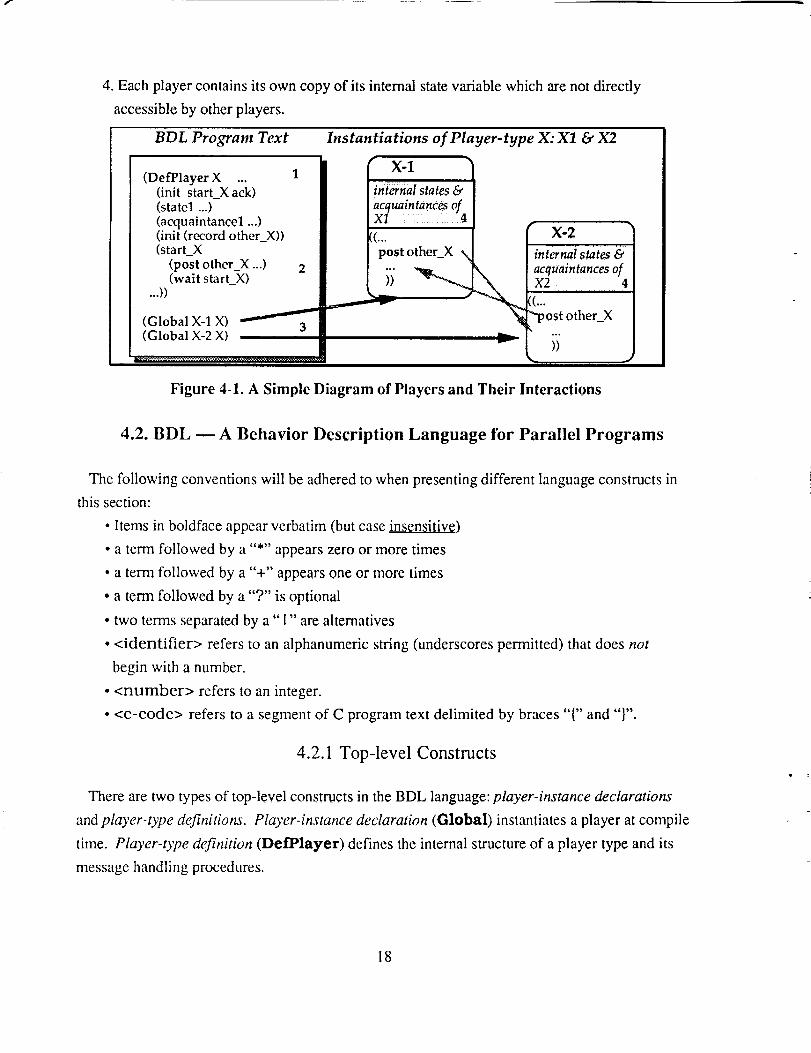
4. Each player contains its own copy of its internal state variable which are not directly
accessible by other players.
BDL Program Text
(DefPlayer X ...(init start_X ack)(statel ...)(acquaintancel ...)(init (record other_X))(start_X
(post otherX ...) 2(wait start_X)
...))
(Global X-1 X)(Global X-2 X)
Instantiations of Player-type X: X1 & X2
l int_nal states&[acquaintanCes ofIX! ..... ......14
I(_;ostothe_X N ,,t_n,,tst_te_e,
L _ _' acquaintanCes of "x24..._.- ((..."*post other X
.)t
Figure 4-1. A Simple Diagram of Players and Their Interactions
4.2. BDL --A Behavior Description Language for Parallel Programs
The following conventions will be adhered to when presenting different language constructs in
this section:
• Items in boldface appear verbatim (but case insensitive)
• a term followed by a "*" appears zero or more times
• a term followed by a "+" appears one or more times
• a term followed by a "?" is optional
• two terms separated by a" I" are alternatives
• <identifier> refers to an alphanumeric string (underscores permitted) that does not
begin with a number.
• <number> refers to an integer.
• <c-code> refers to a segment of C program text delimited by braces "{" and "}".
4.2.1 Top-level Constructs
There are two types of top-level constructs in the BDL language: player-instance declarations
and player-type definitions. Pl®,er-instance declaration (Global) instantiates a player at compile
time. Player-type definition (DefPlayer) defines the internal structure of a player type and its
message handling procedures.
18
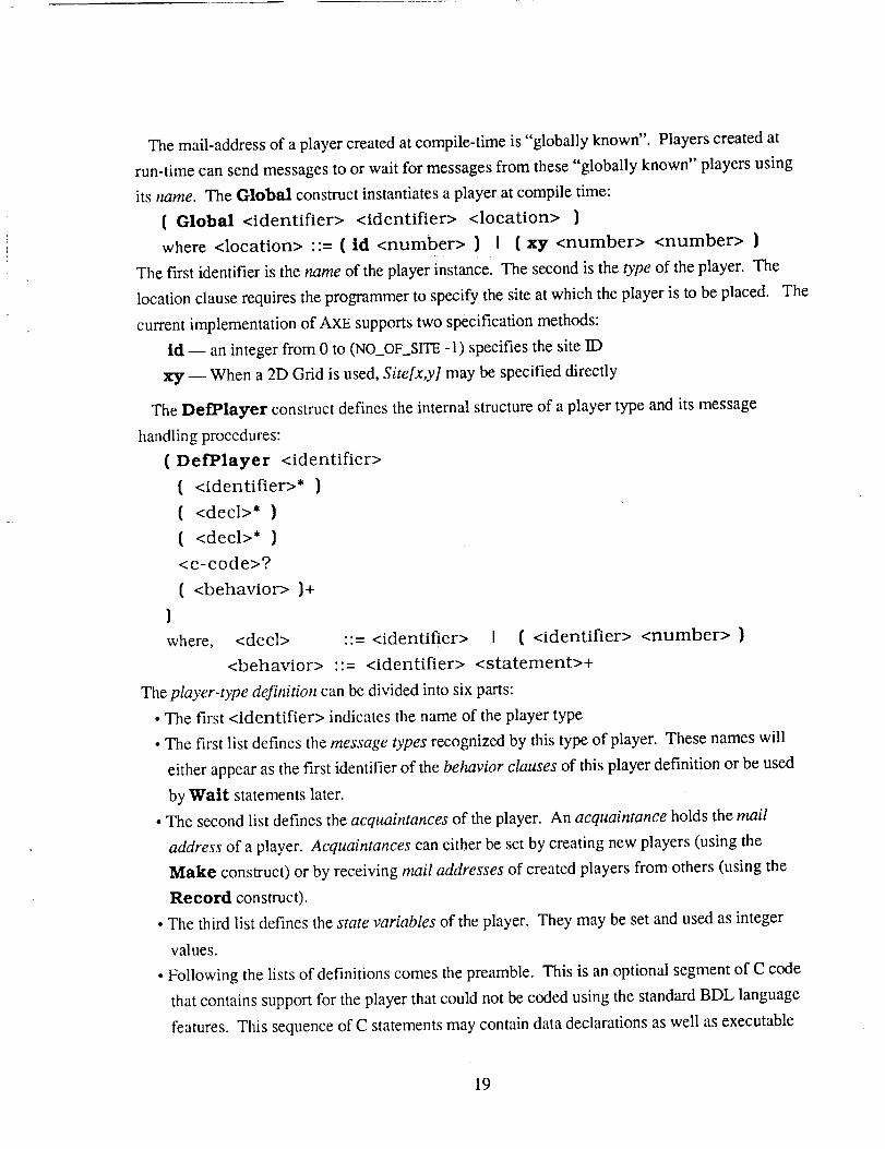
The mail-address of a player created at compile-time is "globally known". Players created at
run-time can send messages to or wait for messages from these "globally known" players using
its name. The Global construct instantiates a player at compile time:
( Global <identifier> <identifier> <location> )
where <location> ::= ( id <number> ) i ( xy <number> <number> )
The first identifier is the name of the player instance. The second is the type of the player. The
location clause requires the programmer to specify the site at which the player is to be placed. The
current implementation of AXE supports two specification methods:
ld -- an integer from 0 to (NO_OFSITE -1) specifies the site ID
xy -- When a 2D Grid is used, Site[x,y] may be specified directly
The Defl_layer construct defines the internal structure of a player type and its message
handling procedures:
( Det'Player <identifier>
( <identifier>* )
( <decl>* )
( <decI>* )
<c-code>?
( <behavior> )+
)
where, <dec1> ::= <identifier> I ( <identifier> <number> )
<behavior> "'= <identifier> <statement>+
The player-type definition can be divided into six parts:
• The first <identifier> indicates the name of the player type
• The first list defines the message types recognized by this type of player. These names wiIl
either appear as the first identifier of the behavior clauses of this player definition or be used
by Watt statements later.
• The second list defines the acquaintances of the player. An acquaintance holds the mail
address of a player. Acquaintances can either be set by creating new players (using the
Make construct) or by receiving mail addresses of created players from others (using the
Record construct).
• The third list defines the state variables of the player. They may be set and used as integer
values.
• Following the lists of definitions comes the preamble. This is an optional segment of C code
that contains support for the player that could not be coded using the standard BDL language
features. This sequence of C statements may contain data declarations as well as executable
19
code. It will beinsertedinto theplayer'sgeneratedcodejust beforethemainmessage
processingloop.
• Thelastpartof theplayerdefinitionis thelist of behavior clauses. Each behavior clause
comes with a head-- indicating the corresponding message type and a tail -- a list of
executable statements. When an idle player receives a message, it checks the in-coming
message's type against the head of each behavior clause. If it finds a match, the tail will be
executed. If not, the message will remain in the buffer and the player remains idle until a
message whose type matches the head of a behavior clause arrives. That message may still
be extracted should the player execute the Wait statement.
Both acquaintances and the state variables may be declared as scalars or vectors (1-dimensional
arrays). Individual elements of the vector may be referred to by the aref construct. Array indices
begin at 0. The user may also insert top-level C code into the file generated by BDL. This code
would likely include data structures and routines that cannot be defined using standard BDL
constructs.
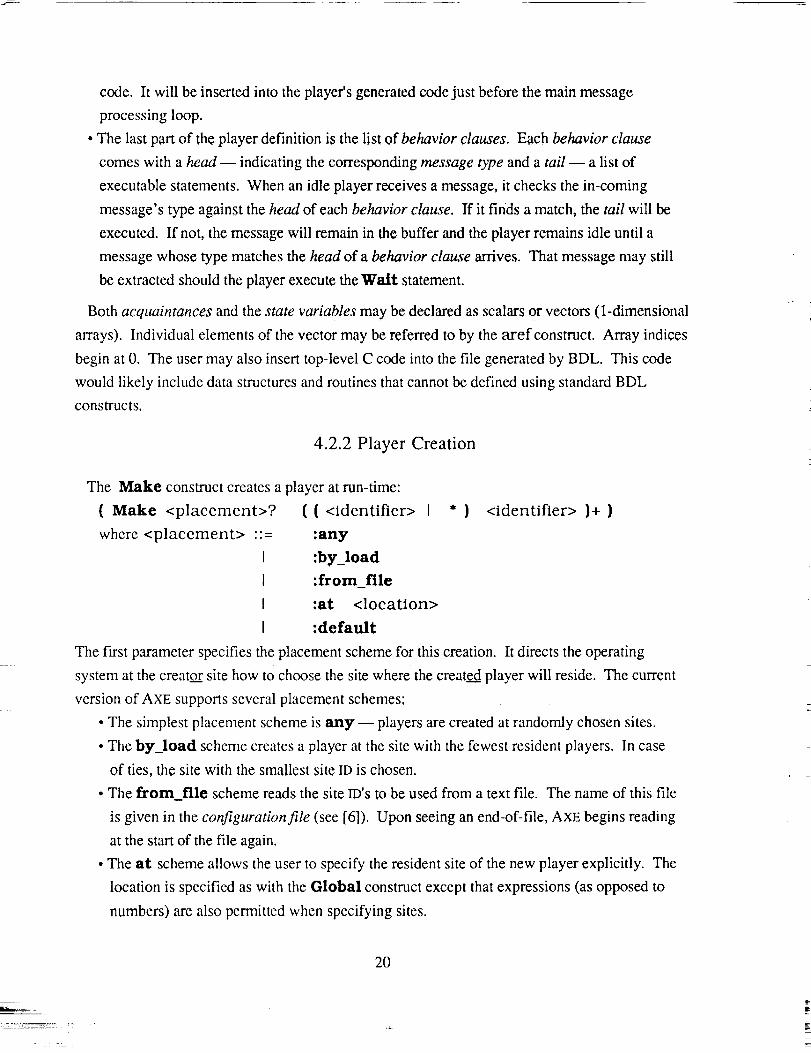
4.2.2 Player Creation
The Make construct creates a player at run-time:
( Make <placement>? ( ( <identifier> I * }
where <placement> ::= :any
I :by_load
I :from_file
I :at <location>
I :default
<identifier> )+ )
The first parameter specifies the placement scheme for this creation. It directs the operating
system at the creator site how to choose the site where the created player will reside. The current
version of AXE supports several placement schemes:
• The simplest placement scheme is any-- players are created at randomly chosen sites.
• The by_load scheme creates a player at the site with the fewest resident players. In case
of ties, the site with the smallest site ID is chosen.
• The from_file scheme reads the site ID's to be used from a text file. The name of this file
is given in the configuration file (see [6]). Upon seeing an end-of-file, AXE begins reading
at the start of the file again.
• The at scheme allows the user to specify the resident site of the new player explicitly. The
location is specified as with the Global construct except that expressions (as opposed to
numbers) are also permitted when specifying sites.
2O

• The default scheme instructs AXE to check the configuration file for the scheme to be
used (see [6]).
The remaining parameters are pairs of slots and player types. The first value of each pair
designates a location for the mail address of the newly created player. If a "*" is given for this
location, the address of the newly created player is thrown away. If an identifier is given, it is
assumed to be either one of the creator player's acquaintances or a global player name.
4.2.3 Data Manipulation
BDL provides support for accessing, modifying, and computing other values with local
variables. As stated above, BDL supports vectors (1-dimensional arrays). Individual elements of
these arrays may be accessed using the Aref construct:
(Aref <identifier> <expression> }
Scalar values may be set using the Setq construct:
( Setq <lhs> <expression> }
where <lhs> :: = { Aref <identifier> <expression> ) I <identifier>
In addition, the value of a scalar may be modified using the Dee and Ine constructs:
( ( Dee I Ine ) <lhs> )
They decrement and increment their argument respectively.
<expression> refers to either a scalar value (either an integer constant or an internal state
variable) or a compound expression built using the BDL operators. In addition, a C code segment
surrounded by braces may be used anywhere an expression is called for. In this way, users may
perform calculations that are not available within standard BDL. BDL provides the basic
arithmetic operators (+, -, *, /) as follows:
(<operator> ( <expression> )+ )
If only one argument is passed, the results for "-" and "/" are the negative and reciprocal of the
argument respectively.
4.2.4 Message Passing
The Post construct is used for message sending:
(Post <acquaintance> <message-type> <message-term>*
where, <message-term> ::= self
1 <acquaintance>
I <expression>
21
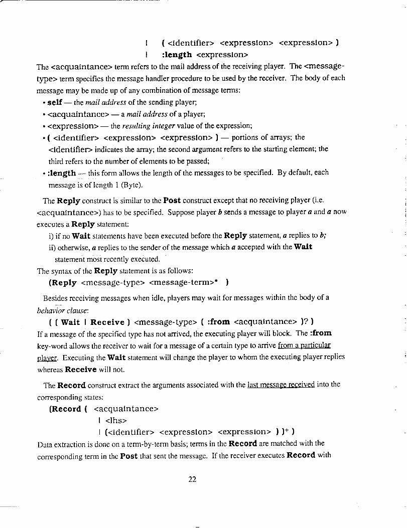
I ( <identifier> <expression> <expression> )
i :length <expression>
The <acquaintance> term refers to the mail address of the receiving player. The <message-
type> term specifies the message handler procedure to be used by the receiver. The body of each
message may be made up of any combination of message terms:
* sell'-- the mail address of the sending player;
* <acquaintance> -- a mail address of a player;
o <expression> -- the resulting integer value of the expression;
. ( <identifier> <expression> <expression> ) -- portions of arrays; the
<identifier> indicates the array; the second argument refers to the starting element; the
third refers to the number of elements to be passed;
° :length -- this form allows the length of the messages to be specified. By default, each
message is of length 1 (Byte).
The Reply construct is similar to the Post construct except that no receiving player (i.e.
<acquaintance>) has to be specified. Suppose player b sends a message to player a and a now
executes a Reply statement:
i) if no Wait statements have been executed before the Reply statement, a replies to b;
ii) otherwise, a replies to the sender of the message which a accepted with the Wait
statement most recently executed.
The syntax of the Reply statement is as follows:
(Reply <message-type> <message-term>* )
Besides receiving messages when idle, players may wait for messages within the body of a
behavior clause:
( (Wait I Reeetve) <message-type> ( :from <acquaintance> )? )
If a message of the specified type has not arrived, the executing player will blockl The :from
key-word allows the receiver to wait for a message of a certain type to arrive from a particular
la_. Executing the Wait statement will change the player to whom the executing player replies
whereas Receive will not.
The Record construct extract the arguments associated with the last message received into the
corresponding states:
(Record ( <acquaintance>
I <lhs>
t (<identifier> <expression> <expression> ))+ )
Data extraction is done on a term-by-term basis; terms in the Record are matched with the
corresponding term in the Post that sent the message. If the receiver executes Record with
22

fewerargumentsthanthesenderdoeswith Post, these extra values will be dropped. On the
contrary, if Record is called with too many arguments, the extras will be filled with zeros.
If a scalar is sent but a vector is expected, the first element of the vector is set to the scalar
received and the remaining elements are set to zero. If a vector is sent but and a scalar expected,
the scalar is set to the In'st element of the vector. If the vector sent is longer than the receiving
vector, as many elements as possible are recorded (without going beyond the bound specified in
the Record). If there are too few, the remaining elements are set to zero.
4.2.5 Flow Control
The If statement evaluates a boolean expression and executes one of two alternatives depending
on the value of the expression:
(If <boolean-expression> <statement> <statement>? )
where, <boolean-expression> ::= <expression>
<relop> ::= < I <-
I ( <relop> <expression> <expression>
I (or <boolean-expression>+ )
I (and <boolean-expression>+ )
J == I <> I >= I >
If the boolean expression evaluates to true (or non-zero), the first statement is executed, otherwise
the second one (if present) is executed. Multiple statements may be encapsulated using the
Progn construct.
The Repeat construct defines a loop to be executed a specified number of times:
(Repeat <expression> <statement>+ )
Branch statements allow probabilistic behavior to be modelled:
( Branch ( ( <expression> <statement>+ ) 1+ )
The Branch statement contains a list of clauses, each of which has a specified probability of
occurring. For example the following statement indicates that the first branch is taken with a
probability of 40%, the next one 50% etc..
(Branch (40 (...) (...) ... )
((+ 20 30) (...) (...) ... )
(I0 (...) (...) ... ))
The current implementation does not check that the probabilities of all the branches add up to
100%. Consider the following statement: (Branch {v1 (... } (...) ... ) (v2 (...) {... )
... ) {v3 (...) (...) ... )). A random number (rn) between 1 and 100 is selected. The first
branch will be taken ifrn < v1; the second branch will be taken if v1 < rn < (V1 + V2), and so on.
23

4.2.6 Miscellaneous
TheRun construct requests to use the processor for a specified duration. It should also be noted
that these "time units" are meaningful only when discussed in conjunction with other
characteristics of the hardware (such as communication link bandwidth and context-switch
overhead etc.). It's syntax is:
( Run <expressions> )
The Hold construct instructs AXE to advance the specified amount of simulation time without
requesting the use of a processor, in other words, the caller player pauses for a specified amount
of time before executing the next statement, It's syntax is:
( Hold <expression> )
The Funeall construct is used to call predefined C routines. Integer arguments are listed after
the function name:
( Ftmeall <function-name> <expression>* )
The Progn construct allows multiple statements to be parsed as a single statement. It is
particularly useful with the If statement discussed earlier:
( Progn <statement>+ )
The Destroy construct terminates the caller player process: ( Destroy )
The Genesis construct marks the beginning of the simulation. All events that occur before
Genesis "take place at time zero". Genesis should be called exactly once at the beginning of
each experiment to start the simulation clock. Genesis requires no argument: ( Genesis )
The Terminate construct is called exactly once at the end of each experiment. It indicates that
simulation is complete. Terminate requires no argument: ( Terminate )
In addition to all the statements described above, BDL permits the user to insert C code
(surrounded by "{" and "}") anywhere a statement is permitted. This allows the user to perform
tasks that are not easily specified using BDL.
4.3. Building Abstract Software Models
The development of abstract software models benefit at least three important research activities in
parallel processing:
. PERFORMANCE EVALUATION OF ALTERNATIVE PROBLEM FORMULATION STRATEGY-
Usually, there is more than one way in which an application can be formulated as computing
24

processesto beexecutedin parallel.Theability to modelthesealternativesquickly and
evaluatetheirperformanceontargetparallelarchitecturesenablessoftwarebottlenecksto belocatedlongbeforetensof man-yearshavebeenspentonactualimplementation.
• PERFORMANCE PREDICTION ON NOVEL HARDWARE SYSTEM ARCHITECTURE- In the design
of large special-purpose hardware systems (such as the Data Management System of Space
Station Freedom), the choice of processors and communication links has to be such that they
can support the software that is going to be run on it. Unfortunately, these decisions have to
be made before the software has actually been written; only abstract functional specifications
exist. The ability to build approximate models from software specification and observe their
performance impact on different processors and communication links will help determine
suitable candidates.
° DEVELOPMENT OF LOAD-BALANCING ALGORITIIMS -- Finally, with the development of
resource management algorithms for highly parallel systems, candidate strategies have to be
tested over a wide range of hardware architectures and applications with different behavior
characteristics to determine its performance and robustness. Simulating program execution
at the instruction level is unnecessary and too time consuming. BDL models preserve
program behavior, and at the same time, enable simulation to proceed quickly, allowing
many experiments to be performed rapidly.
Building parallel program models with BDL involves four basic steps:
i. study and onderstand the program text and structure;
ii. specify the program model in BDL;
iii. identify the portion of computation that can be abstracted:
• use the Rtm statement for data-independent computations; or
° use probabilistic branches otherwise;
iv. simulate the model and compare its behavior with the actual program:
• find out the limitations of the model; and
° make modifications if necessary.
This process is best explained by using two examples -- the N-body problem and Quick-sort.
4.3.1 The N-body Problem
N heavy bodies are suspended in 3-dimensional space at some initial
coordinates. They are subsequently released simultaneously and allowed
to move under the influence of gravitational forces they exert on one
another. The problem: plot their trajectories.
25

A possible distributed formulation involves creating one player for each body (as shown in
Figure 4-2). The computation begins by having a st art message sent to each player. Each
player responds by sending its current position 2 to the other (N-l) players. Whenever the new
position of another body is received, the internal states of the receiver are updated. Its new position
and velocity are calculated, recorded locally and transmitted back to the sender.
(DefPlayer Body PLAYER-TYPE DEFINITION
(init start update) message names
(bl • • • bn-1) mail-addresses and
(my_coords my_velocity crdl crd2 ... crdn-l) numerical states
( ini t INITIALIZATION
(record b 1 b2 • • . bn-1 get neighbors' addresses
Crdl crd2 • • • crdn-1 ) ) & initial positions
( s t ar t STARTMOVING
(post bl update my_coords) tell everybody where I am
• . . and wait for their responses
(post bN_ 1 update my coords))
(update new position arrived!
(if (= sender bl) (record Crdl) find sender & update its position
(setq my_coords compute my position
(funcall compute_new_coords self))
(setq my_velocity and new velocity
(funcall compute new_velocity self))
(post some plotter update my_coords) plot!
(re_l_ update my coords) )) and replythe sender
Figure 4-2. BDL Schematic of a "Body" Player in the N-Body Problem
Two observations can be made:
a) The most time consuming statements in the program text are the ones which compute the
new position and velocity (as indicated by "[[_").
b) The time spent computing these two statements is independent of the actual position of all
the other players.
If the statements in question were replaced (as shown in Figure 4-3) with NO-OP statements that
simply consume time -- (run some__time), the interaction of the program with the
2 In order to keep the code simple, we are only keeping track of one dimension of the bodies; the CRD statevariables could easily be duplicated to hold the other dimensions of the bodies.
26
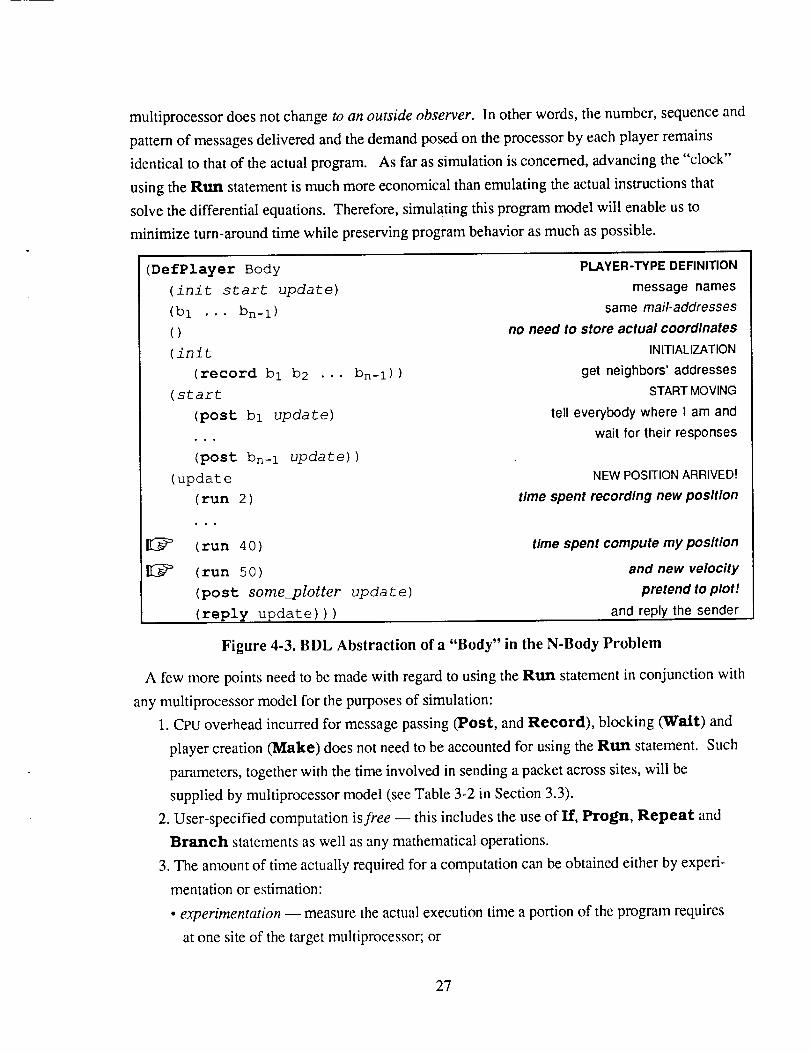
multiprocessordoesnotchangeto an outside observer. In other words, the number, sequence and
pattern of messages delivered and the demand posed on the processor by each player remains
identical to that of the actual program. As far as simulation is concerned, advancing the "clock"
using the Rttn statement is much more economical than emulating the actual instructions that
solve the differential equations. Therefore, simulating this program model will enable us to
minimize turn-around time while preserving program behavior as much as possible.
(DefPlayer Body
(init start update)
(bI ... bn- I)
()
(init
(record bl b2 •••
(start
(post bl update)
(post bn-i update) )
(update
(run 2)
(run 40)
(run 50)
(post some_plotter
(reply update)))
bn-i ))
update)
PLAYER-TYPE DEFINITION
message names
same mail-addresses
no need to store actual coordinates
INITIALIZATION
get neighbors' addresses
START MOVING
tell everybody where I am and
wait for their responses
NEW POSITIONARRIVED!
time spent recording new position
time spent compute my position
and new velocity
pretend to plot!
and reply the sender
Figure 4-3. BDL Abstraction of a "Body" in the N-Body Problem
A few more points need to be made with regard to using the Run statement in conjunction with
any multiprocessor model for the purposes of simulation:
1. CPU overhead incurred for message passing (Post, and Record), blocking (Walt) and
player creation (Make) does not need to be accounted for using the Run statement. Such
parameters, together with the time involved in sending a packet across sites, will be
supplied by multiprocessor model (see Table 3-2 in Section 3.3).
2. User-specified computation is free -- this includes the use of If, l:'rogn, Repeat and
Branch statements as well as any mathematical operations.
3. The amount of time actually required for a computation can be obtained either by experi-
mentation or estimation:
• experimentation -- measure the actual execution time a portion of the program requires
at one site of the target multiprocessor; or
27

• estimation -- generate the corresponding machine instructions (by a compiler) and
estimate the actual number of cycles needed based on a processor architecture.
4. The amount of time units is only meaningful when compared to the delay for message
sending and other CPU overhead charges.
4.3.2 Quicksort
(DefPlayer quickSort
(init done)
(left right master)
(pivot
Unsorted_Array Array_Size Left_Array
(init
(record Unsorted_Array master)
(setq Array_Size (funcall compute_array_size)
(if (<= Array_Size i)
(progn
(post master done Unsorted_Array)
(destroy))
(progn
PLAYER-TYPE DEFINITION
message names
acquaintances
variable list
Right_Array)
INITIALIZATION
get an array
compute its size
check array size
if the above condition is true
send array back to parent
finish, therefore self destruct!
otherwise
(setq pivot (funcall choose Unsorted_Array))
(setq Left_Array partition & exchange array members to get "left" array
(funcall create_lft_array pivot Unsorted_Array)
(setq Right_Array partition & exchange array members --) "right" array
(funcall create_rght_array pivot Unsorted_Array)
(make left quickSort) create a player to sort leftarray
(make right quickSort) create a player t0 sort rightarray
(post left init Left_Array self) send off left array
(post right init Right_Array self) send off right array
(wait done)
(record Left Array)
(wait done)
(record Right_Array)
(setq Unsorted_Array
(funcall merge_arrays
(post master done Unsorted_Array)
(destroy)) ) ) )
wait for acknowledgement from one of the players
left or right array is not important
wait for acknowledgement from the other player
left or right array is not important
merge the two sub-arrays
pivot Left_Array Right_Array))
return sorted array to parent
exit
Figure 4-4. BDL Specification of Quick-Sort
28

An array of numbers is to be sorted. An element of the array (say a) is
chosen to partition the array into two sub-arrays, with elements in one sub-
array < _ and the other sub-array elements > a. This procedure is repeated
recursively until the size of the sub-array is less than or equal to 1. The
sub-arrays are then reassembled recursively into a single sorted array.
In a distributed environment, one player is created for each Quicksort process (as shown in
Figure 4-4). The computation begins by checking whether the size of an array is less than or equal
to l. If the size is greater than 1, the partition and exchange procedures will be processed, and a
player will be created to sort each sub-array. The calling function will wait until both of the called
functions finish their processes, then merges the two sub-arrays into a single array.
(DefPlayer quickSort
(init ack)
(left right master)
(Array_Size
Partition_Time Merge_Time)
(init
(record Array_Size Partition
(if (<= Array_Size i)
(progn
(post master ack)
(destroy))
(progn
(run (* Partition Time
(make left quickSort)
(make right quickSort)
(post
(post
(wait ack)
(wait ack)
(run (* Merge_Time
(post master ack)
(destroy)) ) ) )
PLAYER-TYPE DEFINITION
message names
acquaintances
array size and estimated time
per element to partition & merge arrays
INITIALIZATION
Time Merge_Time master)
check array size
if the above condition is true
send the acknowledgement back to the calling function
exit
if the condition is false
Array_Size) ) time spent partitioning array
create a "left" player to sort "left" sub-array
create a "right" player to sort "right" sub-array
left init (/ Array_Size 2) send parameters to left player
Partition Time Merge_Time self)
right init (/ Array_Size 2) send parameters to right player
Partition_Time Merge_Time self)
wait for acknowledgement from one of the players
wait for acknowledgement from the other player
Array_Size) ) time spent merging two arrays
send acknowledgement back to the caller player
exit
Figure 4-5. BDL Abstraction of Quick-Sort
29

Two observationssimilarto theN-body problem can be made:
a) The most time consuming lines in the program text are the ones which partition and merge
arrays. (as indicated by "[[_").
b) The time spent on these statements is independent of the partition and merge processes of
all the other players.
As far as simulation is concerned, sorting a real array is not required. The time needed to
partition and merge arrays can be estimated as proportional to the array size. If the lines in
question were replaced (as shown in Figure 4-5) with a Run statement, program behavior as
observed by the multiprocessor does not change.
4.4. Summary
BDL can be used to model parallel computations which exploit parallelism explicitly at the
process/procedure level. There are no shared data-structures. Players communicate via
asynchronous message passing. The following computing paradigms can be modelled easily
using players [12]:
• PARALLEL CODE-BODIES -- e.g. fork/join [13, 14], parBegin/parEnd [15];
• COMMUNICATING PROCESSES -- e.g. Concurrent Pascal [16] and CSP [ 17];
• MULTILISP [18],futures [10] and streams [19];
• REMOTE PROCEDURES [11]; and
• a subset of the ACTOR programming paradigm [20] known as the serializers [21].
BDL also provides the necessary constructs to model the following aspects of parallel programs:
• behavior of individual players -- models the different functionality of various computing
agents in the parallel computation;
• player Creation -- both compile-time declaration and run-time creation;
• communication -- for data transfer and synchronization between computing agents; and
• processing in response to messages received -- in order to construct an accurate model, the
processing time can be gathered by monitoring actual program execution or by counting
machine instructions.
As far as building program models is concerned, the data-dependent behavior of programs
remains the biggest challenge for model builders. Although the use of probabilistic branches may
solve some simple cases, it is, in general, very difficult to decide what an appropriate level of
modelling should be.
3O

For example, two alternative player representations of a "file" are shown in Figure 4-6. The
model on the left checks whether the file has already been reserved before granting a user write-
access. The one on the right, however, is built based on an observation that "only (say) 5% of
users try to gain access to files already reserved". BDL allow models of either level to be
specified. It is up to the researcher to decide, recognize and remember what level of abstraction
his/her model was constructed for. A model should never be interpreted beyond its limitations.
(DefPlayer File
(... reserve ...)
(my_writer ...)
(reserve
(if (<> my_writer NIL)
(reply ack NIL)
(progn (setq my_writer sender)
(reply ack T))))
J )
(DefPlayer File
(•.• reserve •..)msgsit understands
(my_writer ...) acquaintance names
(reserve RESERVE msg received
(branch
(.05 (reply ack NIL)) REFUSE!
(•95 (reply ack T))))
• • • )
ACCEPT!
So
Figure 4-6. Two BDL Models of a "File" Player
Conclusions and Future Research
AXE, AN EXPERIMENTATION ENVIRONMENT, is created to facilitate research with resource
management strategies for parallel systems. It provides an integrated environment for the
following activities:
• COMPUTATION MODEL SPECIFICATION using BDL -- a Behavior Description Language
for parallel computations. BDL can be used to describe computation based on various
programming paradigms such as CSP, remote procedures, data-flow, and actors.
•MULTIPROCESSOR ARCHITECTURE SPECIFICATION -- By changing certain simple
parameters, the architecture of the hardware may be modified. This includes inter-
connection topology, network speed, routing algorithms as well as operating system
scheduling algorithms.
• SIMULATION -- A discrete-time event-driven simulator based on CSIM is responsible for
predicting the execution time of BDL program models on various multiprocessor models.
31

• DATA COLLECTION w Data that indicate program behavior and resource utilization/
contention are gathered automatically. These data may be used for evaluation of resource
management strategies as well as software and hardware architecture alternatives.
• EXPERIMENTATION -- The researcher is able to study resource management strategies as
well as various issues in parallel processing such as problem formulation, alternate
hardware architectures, and operating system algorithms.
During simulation, the activities on the multiprocessor are displayed dynamically via a color
monitor. These include message transmission, length of "ready-queue" at each processing
element as well as overall system load.
The AXE Modelling Package is being augmented to model Intel Hypercube 15(iPSC/3) and
various multiprocessor testbed configurations for the NASA High Performance Computing and
Communications Program. Various panels from the AXE Visualization Package will be integrated
with other tools for displaying data collected from these multiprocessor testbeds.
Acknowledgements
The authors would !ike tO acknowledge Roger Bartlett of Digital Equipment Corporation, who
wrote most of the AXE Visualization Package, Christopher Jones of Stanford University who
developed the token-ring multiprocessor model, Arthur Ieumwananonthachai and Lon. C. Chu of
University Of Illinois Urbana-Champaign who developed the iPSC/2 routing model, Sonie Lau of
NASA Ames Research Center who wrote an earlier version of the Visualization Package and
Rafael Villegas of NASA Ames Research Center who wrote an earlier version of the BDL
compiler.
[1]
[2]
[3]
References
J. C. Yan and S. F. Lundstrom. "The Post-Game Analysis Framework -- Developing
Resource Management Strategies for Concurrent Systems". IEEE Transactions on
Knowledge and Data Engineering, pages 293- 309, vol.1, no.3, September 1989.
H. Schwetman. "CSIM: A C-Based, Process-Oriented Simulation Language". in
Proceedings of the Winter Simulation Conference '86, Washington DC, 1986.
H. Schwetman. "CSIM Reference Manual (Revision 14)". MCC Technical Report ACT-
ST-252-87, Rev. 14. Microelectronics and Computer Technology Corporation, 3500 West
Balcones Center Drive, Austin TX 78759. March 1990.
32

[4] A. Malony andD. Reed."VisualizingParallelComputerSystemPerformance".ReportUIUCDCS-R-88-1465,Departmentof ComputerScience,Universityof Illinois atUrbana-
Champaign,September1988.
[5] B. Delagi,N. Saraiya,S.Nishimura,andG.Byrd. "InstrumentedArchitecturalSimulation". ReportKSL-87-65,KnowledgeSystemsLaboratory,Departmentof
ComputerScience,StanfordUniversity,November1987.
[6] C.E. FinemanandJ.C. Yan. "The Axe UserManual". NASA ContratorReport. In
preparation.
[7] H.D. Brown, E. Schoen, and B. A. Delagi. "An Experiment in Knowledge-based Signal
Understanding Using Parallel Architectures". Report KSL-86-69, Knowledge Systems
Laboratory, Department of Computer Science Stanford University, Oct. 1986.
[8] W.J. Dally. "Wire-Efficient VLSI Multiprocessor Communication Networks". in
Advanced Research in VLSI, In Advanced research in VLSI: Proceedings of the 1987
Stanford Conference, Editor, Paul Losleben, pages 390-415, 1987.
[9] P. Kermani and L. Kleinrock. "Virtual Cut-Through: A New Computer Communication
Switching Technique". Computer Networks, 3:267-286, 1979.
[10] H.G. Baker, Jr. and C. Hewitt, "The Incremental Garbage Collection of Processes".
Massachusetts Institute of Technology, AI Lab., AI Working Paper 149, July, 1977.
[ 11 ] B.J. Nelson, "Remote Procedure Call", Xerox Palo Alto Research Center, Palo Alto,
California, Tech. Report CSL-82-8
[12] J.C. Yan. "Parallel Program Behavior Specification and Abstraction using BDL". CSL-
TR-86-298, Computer System Laboratory, Stanford University, August 1986.
[13] M. Conway, "A Muhiprocessing System Design", Proceedings of the AFIPS Fall Joint
Computer Conference, 1963.
[14] J.B. Dennis and E. C. Van Horn, "Programming Semantics for Multiprogrammed
Computations", Communications of the ACM, March 1966.
[15] E.W. Dijkstra, "Cooperating Sequential Processes", Tech. Report EWD-123
Technological Universty, Eindhoven, The Nedelands.
[ 16] P.B. Hansen, "The Programming Language Concurrent Pascal", IEEE Transactions on
Software Engineering, June 1975.
33

[17] C.A.R. Hoare."CommunicatingSequentialProcesses".Communications of the ACM,
August, 1978.
[18] R. Halstead. "Parallel Symbolic Computing". Computer Magazine, 19(8):35-43, August,
1986.
[19] K-S. Weng, "Stream-Oriented Computation in Data Flow Schemas". TM 68,
Massachusetts Institute of Technology, Laboratory for Computer Science, October 1975.
[20] G.A. Agha, "Actors: A Model of Concurrent Computation in Distributed Systems". TR
844, PhD Thesis, Massachusetts Institute of Technology, AI Lab., 1985.
[21] R. Atkinson and C. Hewitt. "Specification and Proof Techniques for Serializers". Memo
438, Artificial Intelligence Laboratory, Massachusetts Institute of Technology, 1977.
34

N/ SA Report Documentation PageNa|onal A_on #mutlcl and
Spmoe Adminisb'atlon
1. Report No.
NASA CR- 177582
2. Govemment Accession No.
4. Title and Subtitle
Modelling Parallel Programs and Multiprocessor Architectures
with AXE
7. Author(s)
Jerry C. Yan and Charles E. Fineman
3. Recipient's Catalog No.
5. Report Date
May 1991
6. Performing Organization Code
8. Performing Organization Report No.
A-91135
10. Work Unit No.
505-64-54
9. Performing Organization Name and Address
Sterling Federal Systems, Inc. 11.
1121 San Antonio Road
Palo Alto, CA 94303 13.
12. Sponsoring Agency Name and Address
Ames Research Center
Moffett Field, CA 94035-1000
Contract or Grant No.
NAS2-13210
Type of Report and Period Covered
Contractor Report
14. Sponsoring Agency Code
15. Supplementary Notes
Point of Contact: Bob Carlson, Ames Research Center, MS 233-15, Moffett Field, CA 94035-1000
(415) 604-6036 or FTS 464-6036
16. Abstract
AXE, An Experimentation Environment for Parallel Systems, was designed to model and simulate for parallel
systems at the "process level." It provides an integrated environment for specifying computation models,
multiprocessor architectures, data collection and performance visualization. AXE is being used at NASA Ames
Research Center for developing resource management strategies, parallel problem formulation, multiprocessorarchitectures, and operating system issues related to the High Performance Computing and Communications
Program. AXE's simple, structured user-interface enables the user to model parallel programs and machines
precisely and efficiently. Its quick turn-around time keeps the user interested and productive.AXE models multicomputers. The user may easily modify various architectural parameters including the
number of sites, connection topologies, and overhead for operating system activities. Parallel computations in AXE
are represented as collections of autonomous computing objects known as players. Players may be used to represent
parallel code-bodies, communicating sequential processes, Halstead's futures, remote procedures, and a subset ofHewitt's actors. A Behavior Description Language (BDL) is used to specify player programs.
Performance data of the multiprocessor model can be observed on a color screen. These include CPU and
message routing bottlenecks, and the dynamic status of the software.
17. Key Words (Suggested by Author(s))
Simulation
Performance evaluation
Parallel processing
High performance computing
16. Distribution Statement
Unclassified-Unlimited
Subject Category - 62
19. Security Classif. (of this report)
Unclassified
20. Security Classif. (of this page)
Unclassified21. No. of Pages
4222. Price
A03
NASA FORM 1626 OCT86For sale by the National Technical Information Service, Springfield, Virginia 22161