Modelling of the passive mobility in human tarsal gears implications from the literature
12
The Foot 14 (2004) 23–34 Review Modelling of the passive mobility in human tarsal gears implications from the literature Peter Wolf ∗ , Alex Stacoff, Edgar Stüssi Laboratory for Biomechanics, Department of Materials, ETH Zurich, Wagistrasse 4, CH-8952 Schlieren, Switzerland Received 28 May 2003; accepted 29 September 2003 Abstract The biomechanics of the human tarsus have been extensively modelled using different types of links within the tarsal bones. Since movement coupling ratios between the calcaneus and tibia have been reported to change continuously, many recent studies accept neither a single rigid hinge joint nor a universal joint representing movement coupling between the rearfoot and lower leg. Traditionally, bony structures and ligaments limiting the range of motion are considered in kinematic chains. However, recent studies suggest distinguishing between limiting (strained) and guiding (isometric) ligaments. The consideration of guiding ligaments in models of tarsal gears has already been shown to improve the simulation of tarsal movements in the sagittal plane. To improve the knowledge on movement coupling, e.g. three-dimensional, additional tarsal gears need to be established. The large discrepancies of the reported movement coupling ratios indicate that there is presently no validation available which allows to characterisation of human tarsal function to an acceptable degree. © 2003 Elsevier Ltd. All rights reserved. Keywords: Modelling rearfoot complex; Human tarsal gears; Passive mobility 1. Introduction Knowledge of gears 1 in the tarsus and adjacent bones is of great importance in biomechanics and orthopaedics. Generally, gears describe a functional relationship between their elements. In a human tarsus, gears are comprised of bones and ligaments (passive elements). Gears are driven by internal and external forces or more precisely, muscles, joint forces and ground reaction forces (driving elements). Regarding the lower extremities the functional relationship within gears is often called movement coupling. In the tarsus and adjacent bones movement coupling en- ables three basic dynamic functions required for human mo- bility: (1) Absorbing impact forces by certain movements of foot and lower limb bones, i.e. damping [2–4]; (2) Providing an optimal support area for the whole body while walking or running by for example, allowing the foot to accommodate to uneven ground or avoiding un- ∗ Corresponding author. Tel.: +41-1-633-61-86; fax: +41-1-633-11-24. E-mail address: [email protected] (P. Wolf). 1 The term gear is used after Leardini et al. [1] instead of the term kinematic chain. Normally, a kinematic chain consists of bones only which is insufficient with regards to the present topic. compensated swings in the body’s centre of mass, i.e. stabilisation [5,6]; (3) Creating a rigid lever for push-off, i.e. propulsion [3,7]. When movement coupling is disturbed by degenerative diseases, congenital deformities or overuse the walking pat- tern is changed [8,9]. Normally, these changes are compen- sated by functional adaptations [10]. The orthopaedic surgeon tries to prevent decreasing mo- bility with various interventions, such as arthrodesis or en- doprothesis. Both kind of operations may be successful in restoring pain free mobility [11]. However, these interven- tions require compensatory mechanisms or adaptations by the patient which may be observed in a change of move- ment coupling between the foot and lower limb [11,12]. Therefore, knowledge of physiological movement coupling arising from human tarsal gears is essential in orthopaedics [13–16]. Movement coupling is important for the activities of daily living and also for recreational activities, especially run- ning. It has been estimated that between one-third and more than half of all runners suffer at least one injury per year [13,17,18]. Among the most typical running injuries are Achilles tendon pain, shin splints and patellofemoral pain syndrome (PFPS) [19]. During the 1970s and 1980s, high impact forces and excessive foot pronation were thought to 0958-2592/$ – see front matter © 2003 Elsevier Ltd. All rights reserved. doi:10.1016/j.foot.2003.09.002
-
Upload
peter-wolf -
Category
Documents
-
view
215 -
download
3
Transcript of Modelling of the passive mobility in human tarsal gears implications from the literature

The Foot 14 (2004) 23–34
Review
Modelling of the passive mobility in human tarsalgears implications from the literature
Peter Wolf∗, Alex Stacoff, Edgar StüssiLaboratory for Biomechanics, Department of Materials, ETH Zurich, Wagistrasse 4, CH-8952 Schlieren, Switzerland
Received 28 May 2003; accepted 29 September 2003
Abstract
The biomechanics of the human tarsus have been extensively modelled using different types of links within the tarsal bones. Sincemovement coupling ratios between the calcaneus and tibia have been reported to change continuously, many recent studies accept neithera single rigid hinge joint nor a universal joint representing movement coupling between the rearfoot and lower leg. Traditionally, bonystructures and ligaments limiting the range of motion are considered in kinematic chains. However, recent studies suggest distinguishingbetween limiting (strained) and guiding (isometric) ligaments. The consideration of guiding ligaments in models of tarsal gears has alreadybeen shown to improve the simulation of tarsal movements in the sagittal plane. To improve the knowledge on movement coupling, e.g.three-dimensional, additional tarsal gears need to be established. The large discrepancies of the reported movement coupling ratios indicatethat there is presently no validation available which allows to characterisation of human tarsal function to an acceptable degree.© 2003 Elsevier Ltd. All rights reserved.
Keywords: Modelling rearfoot complex; Human tarsal gears; Passive mobility
1. Introduction
Knowledge of gears1 in the tarsus and adjacent bonesis of great importance in biomechanics and orthopaedics.Generally, gears describe a functional relationship betweentheir elements. In a human tarsus, gears are comprised ofbones and ligaments (passive elements). Gears are drivenby internal and external forces or more precisely, muscles,joint forces and ground reaction forces (driving elements).Regarding the lower extremities the functional relationshipwithin gears is often called movement coupling.
In the tarsus and adjacent bones movement coupling en-ables three basic dynamic functions required for human mo-bility:
(1) Absorbing impact forces by certain movements of footand lower limb bones, i.e. damping[2–4];
(2) Providing an optimal support area for the whole bodywhile walking or running by for example, allowing thefoot to accommodate to uneven ground or avoiding un-
∗ Corresponding author. Tel.:+41-1-633-61-86; fax:+41-1-633-11-24.E-mail address: [email protected] (P. Wolf).1 The term gear is used after Leardini et al.[1] instead of the term
kinematic chain. Normally, a kinematic chain consists of bones only whichis insufficient with regards to the present topic.
compensated swings in the body’s centre of mass, i.e.stabilisation[5,6];
(3) Creating a rigid lever for push-off, i.e. propulsion[3,7].
When movement coupling is disturbed by degenerativediseases, congenital deformities or overuse the walking pat-tern is changed[8,9]. Normally, these changes are compen-sated by functional adaptations[10].
The orthopaedic surgeon tries to prevent decreasing mo-bility with various interventions, such as arthrodesis or en-doprothesis. Both kind of operations may be successful inrestoring pain free mobility[11]. However, these interven-tions require compensatory mechanisms or adaptations bythe patient which may be observed in a change of move-ment coupling between the foot and lower limb[11,12].Therefore, knowledge of physiological movement couplingarising from human tarsal gears is essential in orthopaedics[13–16].
Movement coupling is important for the activities of dailyliving and also for recreational activities, especially run-ning. It has been estimated that between one-third and morethan half of all runners suffer at least one injury per year[13,17,18]. Among the most typical running injuries areAchilles tendon pain, shin splints and patellofemoral painsyndrome (PFPS)[19]. During the 1970s and 1980s, highimpact forces and excessive foot pronation were thought to
0958-2592/$ – see front matter © 2003 Elsevier Ltd. All rights reserved.doi:10.1016/j.foot.2003.09.002
24 P. Wolf et al. / The Foot 14 (2004) 23–34
increase running injuries but no clear relationship could beestablished[20,21]. Currently, the main contributing factorstowards many injuries are thought to be a disturbed musclecontrol and an unphysiological movement coupling betweencalcaneal eversion and tibial internal rotation. However, theimportance of theses factors remain unproven. As a con-sequence, well determined knowledge about the effects oftreatments such as orthoses or physiotherapy is still deficient[22,23]. Hence, manufacturers and orthotists need a funda-mental understanding of physiological movement couplingof human tarsal gears[13,24].
The purpose of this paper is to review the literatureconcerning the passive mobility in human tarsal gearsand the resulting movement coupling between the tarsusand adjacent bones, respectively. The review puts especialemphasis on investigations that deal with passive factorsinfluencing movement coupling. The aim is to provide abasis for biomechanical models which describe the func-tionality of the tarsus and adjacent bones. Furthermore, therelevant literature is reviewed to provide an idea of howtarsal models may be validated and of how to discuss theresults of movement coupling gained in previous investiga-tions.
Not reviewed are problems related to single tarsal jointkinematics (see[25]), to the anatomy of relevant bones[26],to pressure distribution and joint forces (see[10]) and tomuscle activity[9].
After a short section of conventions the relevant literatureis divided in the following way: history of method, type oflinkage, influence of ligaments, validation.
2. Conventions
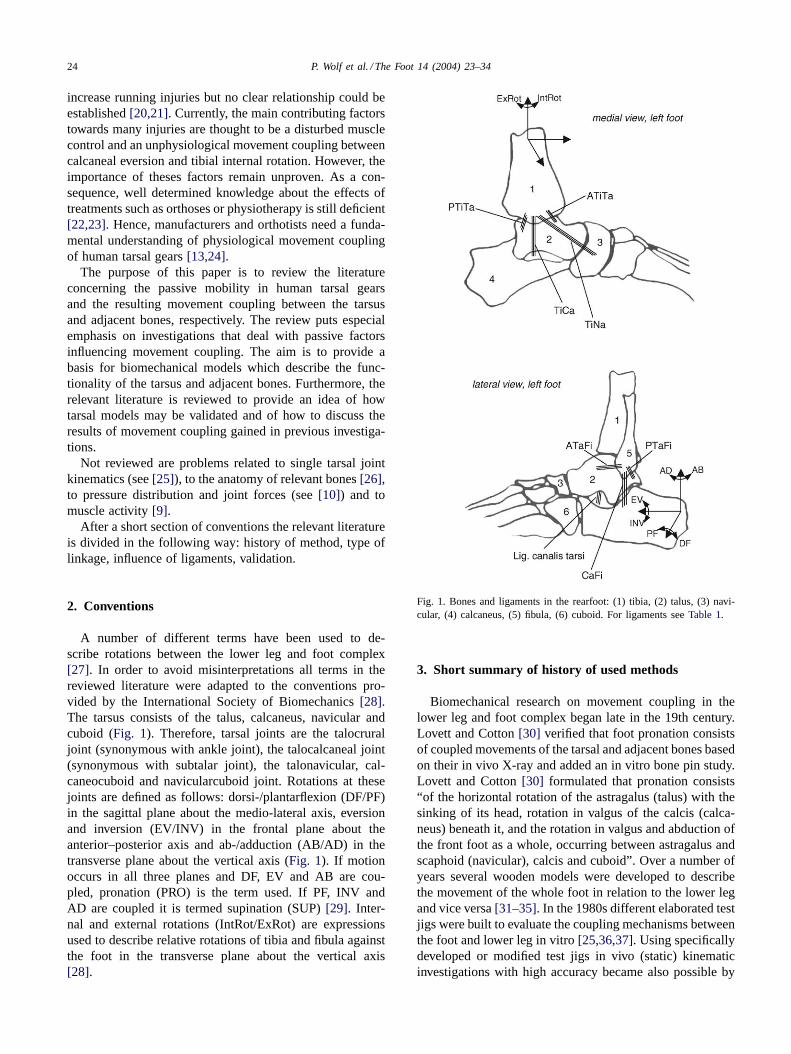
A number of different terms have been used to de-scribe rotations between the lower leg and foot complex[27]. In order to avoid misinterpretations all terms in thereviewed literature were adapted to the conventions pro-vided by the International Society of Biomechanics[28].The tarsus consists of the talus, calcaneus, navicular andcuboid (Fig. 1). Therefore, tarsal joints are the talocruraljoint (synonymous with ankle joint), the talocalcaneal joint(synonymous with subtalar joint), the talonavicular, cal-caneocuboid and navicularcuboid joint. Rotations at thesejoints are defined as follows: dorsi-/plantarflexion (DF/PF)in the sagittal plane about the medio-lateral axis, eversionand inversion (EV/INV) in the frontal plane about theanterior–posterior axis and ab-/adduction (AB/AD) in thetransverse plane about the vertical axis (Fig. 1). If motionoccurs in all three planes and DF, EV and AB are cou-pled, pronation (PRO) is the term used. If PF, INV andAD are coupled it is termed supination (SUP)[29]. Inter-nal and external rotations (IntRot/ExRot) are expressionsused to describe relative rotations of tibia and fibula againstthe foot in the transverse plane about the vertical axis[28].
Fig. 1. Bones and ligaments in the rearfoot: (1) tibia, (2) talus, (3) navi-cular, (4) calcaneus, (5) fibula, (6) cuboid. For ligaments seeTable 1.
3. Short summary of history of used methods
Biomechanical research on movement coupling in thelower leg and foot complex began late in the 19th century.Lovett and Cotton[30] verified that foot pronation consistsof coupled movements of the tarsal and adjacent bones basedon their in vivo X-ray and added an in vitro bone pin study.Lovett and Cotton[30] formulated that pronation consists“of the horizontal rotation of the astragalus (talus) with thesinking of its head, rotation in valgus of the calcis (calca-neus) beneath it, and the rotation in valgus and abduction ofthe front foot as a whole, occurring between astragalus andscaphoid (navicular), calcis and cuboid”. Over a number ofyears several wooden models were developed to describethe movement of the whole foot in relation to the lower legand vice versa[31–35]. In the 1980s different elaborated testjigs were built to evaluate the coupling mechanisms betweenthe foot and lower leg in vitro[25,36,37]. Using specificallydeveloped or modified test jigs in vivo (static) kinematicinvestigations with high accuracy became also possible by

P. Wolf et al. / The Foot 14 (2004) 23–34 25
marking the bones of interest with radiographic absorbingmaterials[12,38]. In the 1990s, movement coupling in thetarsus and adjacent bones was evaluated during locomotionusing skin markers[39–42]and by bone pins[19]. Recently,a dynamic cadaver measurement device was developed[43]to evaluate movement coupling between foot bones undercertain muscle forces introduced by actuators. Newer meth-ods like resonance imaging and electromagnetic trackingdevices have also been used to investigate movement cou-pling in the tarsal joints non-invasively and with improvedaccuracy[44–47].
In summary, movement coupling in the lower leg andfoot complex has been investigated for more than 100 yearswith different methods. Despite all efforts to understand thefunction of the tarsus during gait, uncertainties remain, thus,movement coupling in the lower leg and foot complex re-mains a topic that still needs more investigations, maybeeven new methods.
4. Type of linkage between the rearfoot and lower leg
Modelling of movement coupling arising from humangears in the tarsus and adjacent bones demands answersconcerning the number of degrees of freedom within thestudied bones. For that purpose, this section is divided intothree parts. Firstly, the literature is reviewed concerning theassumption that specific joints can be defined within tarsalbones. Secondly, studies are summarised which simulatemovement coupling between the tarsus and lower leg byone single joint. Thirdly, publications are summarised whichdiscuss the tarsus as a kinematic chain or gear.
4.1. Joints in the tarsus
4.1.1. Ankle and subtalar jointConcerning modelling of the ankle and subtalar joint the
investigations of Isman and Inman[33,48] are often cited.To determine whether these two joints behave as single axisjoints and if so what orientation they have, Isman and Inman[48] investigated 46 specimens in a special test jig. The axeswere determined by those lateral and medial points, respec-tively, which showed the least amount of displacement whilemoving the relevant bones against each other. Isman and In-man[48] found a moving axis for both joints but they statedthat the ankle and subtalar joint can be simplified as singleaxis joints for certain purposes. In a subsequent considera-tion, Inman[32] mentioned that the subtalar joint is anatom-ically complicated but acts functionally as a simple hingejoint. He developed a wooden model with an inclined axisrepresenting an average of those he found in the anatomicalstudies to explain the mechanism of horizontal leg rotationupon a fixed foot[32]. Later, Inman extended this work to afinal number of 107 specimens including the old cases[33].Once again it was found that a single rigid axis for the an-kle or the subtalar joint could not be established through the
whole possible motion arc in these joints. While knowingthese facts, Inman[33] repeated the earlier made statementthat, for all practical purposes, motion about the ankle andsubtalar joints can be locked at to be each about a singlerigid axis. This consideration complies with several anatom-ical studies of the first decades of the 20th century, e.g. Cun-ningham[49], Strasser[50] and Braus[51], and also laterwith in vitro investigations[52].
The single rigid axes approach to the ankle and sub-talar joint was used in several biomechanical models toexamine kinematics and kinetics of the rearfoot. Stauf-fer et al. [53] proposed a two-dimensional foot modelwith one single rigid axis to predict ankle joint forces.Likewise Salathe et al.[54] started their kinetic examina-tion with a two-dimensional hinge joint model, the latestthree-dimensional version of their model being publishedrecently [55]. Further three-dimensional rearfoot modelsusing rigid hinges for the ankle and subtalar joint in accor-dance with the work of Inman have been described[56–60].
Scott and Winter[61] attempted a validation of the as-sumed fixed hinge joints. The individual axes of rotation ofthe ankle and subtalar joint were found by manual manipula-tion and identification of locations with the least motion onthe skin of three different subjects. The authors used the con-cept that for validation the excursions of certain skin mark-ers during motion should produce circles if the line of sightis coinciding with the axis of the assumed hinge joint. Scottand Winter[61] mentioned that during the foot flat phase ofwalking Inman’s proposed assumption of fixed hinge jointsis warranted. But during heel strike and toe off the devia-tions from a circular arc were within 5–10% of the radiusfor all subjects. Hence, Scott and Winter[61] concluded thatduring walking the general assumption of fixed ankle andsubtalar hinge joints is questionable. Recently, Leardini andO’Connor[14] confirmed this conclusion. They investigatedthe lever arms of the main flexor and extensor muscles ofthe ankle by a mathematical model and reported that thedisplacement of the centre of rotation significantly affectsthe muscle lever arm lengths. They concluded that anklemodels with a fixed centre of rotation are only acceptablein exercises with a limited range of motion near the neutralposition.
Inman[33] found no single rigid axis for movements atthe ankle and subtalar joints in his experiments. This wasalso stated earlier by Fick[62] for the subtalar joint. Barnettand Napier[63] investigated more than 150 foot specimensand reported that the changing axis of the ankle joint is dueto the medial profile of the talus with two different arcs andradii, respectively. They showed that in PF, the axis of theankle joint is inclined downwards and medially in the frontalplane, but it is inclined downwards and laterally during DF.This has been confirmed later by studies regarding the ankleand/or subtalar axis in vitro[15,16,31,64–67]and in vivo[8].
Lundberg et al.[68] investigated in vivo the resulting tib-ial rotations in the transverse plane due to calcaneal PF/DF.

26 P. Wolf et al. / The Foot 14 (2004) 23–34
He used the moving ankle axis to explain the change of tibialIntRot to tibial ExRot towards maximal calcaneal DF. Withan input movement of tibial ExRot the deviation and incli-nation of helical axes describing movements between lowerleg and hindfoot bones varied. This result was previouslyshown in vitro[25,36]and in vivo[38]. All of these studiesconfirmed that neither the ankle nor the subtalar joint havea single rigid axis during the entire range of motion.
4.1.2. Distally located tarsal jointsIn contrast to the ankle and subtalar joints less attention
has been devoted to the more distal tarsal joints. The contri-bution in walking of the other hind- and midfoot joints hasbeen adequately demonstrated over the last 15 years[68–70].
The talonavicular joint is regarded by all authors asball-and-socket joint with firm ligaments preventing mul-tiaxial movement[30,71]. Hicks [31] highlighted that thetalonavicular articulation is part of two joints: on the onehand it forms the talo-calcaneal-navicular joint complex,on the other hand it forms together with this complex andthe calcaneal–cuboid articulation the Chopart or midtarsaljoint. The spherical shape of the head of the talus is requiredto enable the hinge type movements in these two joints totake place. Huson[72] also stated that the talonavicularball-and-socket joint is necessary to combine movementsoccurring in adjacent bones. This statement points out thatcertain tarsal joint movements seem to interact with eachother in a distinct way, a fact that will be reviewed inSection 4.3.
In the relevant literature motion in the Chopart or mid-tarsal joint is controversially discussed. The midtarsal jointmotion is thought to take place simultaneously at two hingeaxes: at an oblique and at a longitudinal axis[73]. Manter’s[73] remarks are based on an in vitro foot study in whichmotion in the tarsal joints was produced manually. Manter’sresults and opinion of simultaneously midtarsal movementsabout different hinge joints have not seriously been ques-tioned until recently. Nester et al.[74] pointed out that thesimultaneous movement of midtarsal joint pronation (aboutone axis) combined with midtarsal joint supination (aboutthe other axis) could occur according to Manter[73]. How-ever, since the members of the midtarsal joint would haveto move in two opposite directions at the same time, thereis obviously a contradiction. Nester et al.[75] investigatedthree-dimensional kinematics of the fore- and rearfoot dur-ing Int/ExRot in vivo. They calculated one axis for mid-tarsal motion which has been shown to change remarkablythrough stance phase[74].
It is generally accepted that the navicular and cuboidbones act as a unit and perform motion at the midtarsal joint[71–73,76]. Ambagtsheer[77] measured only two and sixrelative rotation in the frontal plane between the navicularand cuboid during 35 and 50 of ExRot. van Langelaan[25]used a specially built test jig and performed ExRot to 10 footspecimens. He reported that the bundles of helical axes foundfor calcaneocuboid and navicularcalcaneal movements lay
closely together. Hence, motion between the navicular andcuboid is neglible.
In summary, the first part of this section manifests thatthe ankle and subtalar joint can generally be modelled ashinge joints, but that the orientation of these joint axes mustbe adjusted depending on the investigated point in time orphase of the gait cycle. Based on the reviewed literature, thesecond part of this section reveals that an explicit modellingof the midtarsal joint is controversially discussed. However,if better understanding of tarsal gears is attempted furtherstructures besides the bones may have to be included intothe model. This point will be picked up inSection 4.3.
4.2. Simulation of movement coupling by one single joint
In the first part ofSection 4proposed mechanisms of sin-gle tarsal joints were reviewed. In this section, the literatureassuming one joint mechanism at the rearfoot complex toexplain movement coupling is summarised.
Making the assumption of a hinge joint to understandmovement coupling between the lower leg and rearfoot hasthe longest tradition. In 1917, Strasser[50] mentioned thatInt/ExRot of the tibia is only possible at the subtalar jointand as a consequence of rotation of the foot about its lon-gitudinal axis. Subsequently, it was gradually accepted thatInt/ExRot takes place as a result of the oblique to all cardinalplanes orientation of the subtalar axis. Jones[34] explainedby means of a wooden model that “on account of the obliq-uity of the axis of the subtalar joint a lateral torque in thetibia produces a component of force which acts to invert thefoot”. Hicks [31] reported that the double movement, leg ro-tation and foot pronation, is a simple hinge joint movementat the subtalar joint. He developed another wooden model todemonstrate that “when the foot tends to supinate (. . . ), theleg rotates laterally, and when the foot tends to pronate, theleg rotates medially”. Rubin[35] also developed a woodenmodel and confirmed the results of Hicks[31]. Inman[33]modified his 1969[32] developed wooden model (see above)to show that lower leg and foot rotations depend on differ-ent orientations of the subtalar joint. The linear relationshipwithin lower leg and foot rotations depending on the hingeaxis orientation[33] was investigated in vitro by Hinter-mann and Nigg[78]. They reported an almost linear relation-ship within calcaneal EV and tibial IntRot with an averagedmovement coupling ratio of 0.46 (quotient IntRot/EV). Therelationship within calcaneal INV and tibial ExRot was alsofound to be linear; the averaged movement coupling ratio(quotient ExRot/INV) about 0.74 was higher, however[78].This agrees with Inman’s[33] previously discussed theory.
Instead of using a hinge joint to explain movement cou-pling between the foot and lower leg Lapidus[79] andmore explicitly Wright et al.[29] proposed the model of auniversal joint. Wright et al.[29] mentioned the foot as onemember of the joint, the leg as the other; the interposed axesreflecting the ankle and subtalar joint axis. Wright et al.[29] remarked that contrary to the axes of a universal joint,
P. Wolf et al. / The Foot 14 (2004) 23–34 27
the ankle and subtalar axis neither intersect nor are theymutually perpendicular. But Wright et al.[29] were able toexplain the experimentally observed tibia rotation duringfoot flexion on the basis of a universal joint. Foot flexionoccurred not in a plane perpendicular to the ankle axis,hence rotation about both universal joint axes is necessaryand consequently, the tibia rotates about its long axis[29].
Olerud and Rosendahl[5,80] revived the idea of a uni-versal joint within the foot and lower leg. They mentionedthat the mortise and the trochlea tali may be regarded asone fork, the talus acting as the centre piece and that cal-caneus, cuboid and navicular works as another fork. Olerudand Rosendahl[5,80] investigated 10 specimens in a test jigallowing EV/INV, PF/DF and Int/ExRot, and found a nearlylinear relationship within foot INV and tibial ExRot: Perdegree of inversion an average external rotation of 0.44◦ oc-curred. The distal fork constituted a three segment linkedsystem (cuboid–calcaneus, calcaneus–talus, talus–navicular)with varying geometrical properties during the range of mo-tion. This was used as explanation for the also observedtorsion-transmitting changes and did not contradict the pro-posed universal joint approach[5,80].
The assumption of a universal joint acting within thelower leg and rearfoot was also integrated in several math-ematically models[55,81]. Both hinge and universal jointapproaches implies that the movement coupling ratio in onedirection is inversely proportional to that in the opposite di-rection. Hintermann and co-workers[13,78] evaluated thisfact in vitro. They used a modified test jig of Engsberg[36]which allowed among other features tibial rotation aboutits longitudinal axis and foot EV/INV. Hintermann andco-workers[13,78] reported that the movement couplingratio induced by a foot excursion was not identical to theopposite case where motion is induced by tibial rotation. Inparticular, every degree of calcaneal EV resulted in average0.46◦ of tibial IntRot; but, every degree of tibial IntRot ex-cursion resulted in only average 0.08◦ of calcaneal EV. Thisdemonstrates that the movement coupling of calcaneus andtibia for a given input movement depends in the directionof transfer. The dependence can neither be simulated by ahinge nor by a universal joint[13,78].
Stacoff et al.[82,83] investigated movement coupling be-tween the calcaneus and tibia in vivo. The results of fivesubjects running with intracortical bone pins with reflectivemarker triads show that the average movement coupling ratiobetween calcaneal frontal and tibial transverse plane motionchanges during stance. Between heel strike and midstanceevery degree of calcaneal EV was coupled with 0.58◦ oftibial IntRot, between midstance and take-off every degreeof calcaneal INV was followed by 0.46◦ of tibial ExRot.Hence, the authors concluded that the movement couplingbetween foot and lower leg is far more complex than a hingeor universal joint[82,83].
In summary, this section clarifies that neither a single rigidhinge nor a universal joint can simulate movement couplingbetween the lower leg and rearfoot during the whole stance
phase. It remains to be seen whether a hinge or universaljoint may be applied for a selected duration of the stancephase, which would require an adapted definition of theseaxes. However, since movement coupling between tibia andcalcaneus seems to be dependent on the direction of transfer,the one segment which causes the other to move has to bedetermined.
4.3. Tarsal kinematic chain or tarsal gears
The preceding section reveals that the explanation ofmovement coupling between the lower leg and foot as asingle joint is somewhat unsatisfactory. In this section theliterature is reviewed in which the interaction of all tarsaljoints (reviewed inSection 4.1) is described by a kine-matic chain or tarsal gear instead of by the single jointapproach (reviewed inSection 4.2) to explain movementcoupling.
Huson[72] assumed in his thesis that movement of thetalus causes a prescribed motion of both calcaneus andnavicular/cuboid; the latter two are said to move togetheras a block. Furthermore, this closed kinematic chain wasthought to be invertible and talar transverse rotation to beequal to tibial Ex/IntRot. Huson[72] confirmed his closedkinematic chain assumption by an in vitro investigation of14 specimens. By manually exposing Huson[72] showedthat “movement of each tarsal bone involves a shift suchthat it must be followed (or better accompanied) by a shiftof the neighbouring bones”. Hence, Huson[72] concludedthat motion in the subtalar joint is as prescribed followedby talonavicular and then calcaneocuboid joint motion andvice versa. The mobility of this closed kinematic chain be-comes reduced almost completely after fusing one of thetarsal bones; therefore, there is only one degree of freedomfor the whole tarsal mechanism. Huson[72] emphasisedtwo other conceptions related to the closed tarsal kinematicchain: tarsal joints are poly-axial and ligaments control thetarsal movements. Huson et al.[84] later confirmed bothconceptions by a roentgen-photogrammetry study. Theyfound that tarsal joints function in a reproducible man-ner about axes whose orientations change continuouslyduring motion. While changing the motion direction theviscoelastic ligament properties became evident[84]. In1986, Huson et al.[85] stated that the closed tarsal kine-matic chain can be driven by lower leg rotation but therewas a remarkable difference between the tibial and talarrotations. This tibiotalar delay was thought to be causedby the initially insufficient tension of horizontal tibiota-lar ligaments, especially the anterior talofibular ligament;only after tension has built up the talus followed tibialmotion [85].
Ambagtsheer[77] investigated tarsal movements withbone pins in every tarsal bone. The observed results led tothe conclusion that the tarsal bones constitute a closed kine-matic chain independent of input movement and influencedby ligaments. This is in agreement with Huson[72].
28 P. Wolf et al. / The Foot 14 (2004) 23–34
Nester[86] is associated with the closed tarsal kinematicchain approach in his literature review concerning the rear-foot complex. But he also stated that up to that point in timethe literature lacked a specific description of a functionalmodel for the tarsus. Nester[86] remarked that the anklejoint mainly provides DF/PF, the subtalar joint EV/INV andthe midtarsal EV/INV as well as AB/AD and that the com-bined movements PRO/SUP are realised at a “rearfoot com-plex axis”. The orientation of this rearfoot complex axis isthought to be influenced by all three joint axis orientationswhat involves a great individual variation in rearfoot axisorientation. Nester[86] proposed to categorise patients interms of the orientation of their rearfoot complex axis andto develop a functional model for each category. However,Nester and co-workers have not published concrete modelrealisations to date.
An adequate consideration of the guiding function of lig-aments in tarsal modelling has been proposed only 10 yearsago. At first, DF/PF at the ankle joint was modelled as afour bar linkage[66]. This ankle gear consists of the tibiaand talus and is controlled by the anterior talofibular whichwas already proposed by Huson[72] and the calcaneofibularligament. This ankle gear allows a rotary and gliding com-ponent of the tibia against the trochlea tali. Thoma et al.[66] confirmed their four bar linkage by an in vitro X-rayinvestigation of six foot specimens.
Leardini et al.[1] built a test jig to move six rearfoot spec-imens through their range of DF/PF while applying only theminimum necessary load to drive passive flexion. The rear-foot complex was constrained only by the passive structuresof the joints. Leardini et al.[1] evaluated that the path ofcalcaneal motion with respect to the tibia during DF wasvirtually the same as in PF. Most of the motion occurred atthe ankle, less at the subtalar joint. It was also shown thatthe calcaneofibular (CaFi) and the tibiocalcaneal (TiCa) liga-ments remain nearly isometric. Leardini et al.[87] extendedtheir work and concluded that the entire rearfoot complexcan be regarded as a single degree of unrestricted freedommechanism. They modelled this mechanism as a four barlinkage consisting of the tibia and fibula, the hind foot bonesand the two isometric CaFi and TiCa ligaments. This gearwith one degree of unrestricted freedom was mentioned todescribe the rearfoot complex during DF/PF in an unloadedcondition [87]. Subsequently, retinacula and muscle unitswere implemented in this two-dimensional model; further-more, the model was proved under the conditions of anklejoint prostheses[65,88].
In summary, the closed tarsal kinematic chain approachwith one degree of freedom is well accepted in literature.However, the evaluation of passive and driving elementsof tarsal gears to explain certain tarsal movements is stillin the beginning. The consideration of guiding ligamentsmay provide a better basis for modelling complex movementbehaviours between tarsal bones than for modelling based onbony structures and ligaments limiting the range of motiononly.
5. Ligaments in tarsal gears
The generally accepted role of the tarsal ligaments is toprevent multiaxial movements and to limit the range of mo-tion at tarsal joints (seeSection 4.1). However, more recentpublications distinguish explicitly between two differentstrain behaviours and thus, two different roles of the tarsalligaments. One behaviour is described with an increasingor decreasing ligament length during a particular motion.Hence, such ligament behaviour would limit the particularmotion. The other behaviour is based on the observation thatligaments may be maximally strained by±3%; a behaviourwhich is devoted as “isometric”[1]. Hence, such isometricligament behaviour could guide a motion. The distinction ofthese two behaviours is important when attempting to modelthe human tarsus, because limiting ligaments act somehowlike a rope in contrast to guiding ligaments which act ratherlike a bar. Leardini et al.[1] developed their four bar link-age model exactly from this point of view (seeSection 4.3).Two of the bars were represented by the calcaneo-fibularand tibio-calcaneal ligaments due to their isometric be-haviour during DF/PF. To provide further similar justifiedtarsal gears, a literature summary about the qualitativestrain behaviour of the main rearfoot ligaments during cer-tain foot motions is given inTable 1. Note that, e.g. theanterior tibio-fibular ligament may be regarded as a guidinglink during foot EV/INV, however, that has to be provedin future tarsal gear models. Among others, Luo et al.[89]provide information on ligament geometry, Attarian et al.[90] and Siegler et al.[91] on the material properties ofligaments.
The behaviour of tarsal ligaments was also investigated by(sequentially) cutting ligaments and measuring the changesin the range of motion in certain tarsal joints[98–101] orin movement coupling between calcaneus and tibia[102].But based on the results of these investigations no decisioncan be made whether a ligament guides or limits a mo-tion. Both guiding and limiting ligaments are under stress;hence, cutting either ligament increases the range of mo-tion.
In summary, one can conclude that future tarsal investi-gations should evaluate whether the explicit distinction ofguiding and limiting behaviour of ligaments and their ef-fects on tarsal gears may help to improve the understandingof movement coupling at the tarsus.
6. Validation of tarsal gears
After modelling the tarsus (seeSections 4 and 5) it isreasonable to validate these models. Thus, this section sum-marises in vitro and in vivo investigations which concen-trate on validation procedures. Additionally, a comparisonof static versus dynamic investigations is provided and theeffect of tibial load on the biomechanics of the tarsal bonesis reviewed.

P. Wolf et al. / The Foot 14 (2004) 23–34 29
Table 1Summary of reported rearfoot ligaments, the motion in which they become strained, and the type of strain behaviour. For position seeFig. 1
Ligament Motion Strain behaviour Literature
Calcaneofibular (CaFi) Foot DF/PF Isometric in DF/PF Renstrom et al.[92]Bruns and Rehder[93]Leardini et al.[87]
Isometric in PF Luo et al.[89]Increased in max. DF Colville et al.[94]
Nigg et al. [95]Cawley and France[96]Luo et al. [89]Parenteau et al.[97]
Foot EV/INV Isometric in EV Luo et al.[89]Increased in INV, decreased in EV Renstrom et al.[92]
Colville et al. [94]Nigg et al. [95]Luo et al. [89]Parenteau et al.[97]
Foot AB/AD Increased in AB Renstrom et al.[92]Colville et al. [94]Nigg et al. [95]
Anterior talofibular (ATaFi) Foot DF/PF Increased in PF Renstrom et al.[92]Nigg et al. [95]Cawley and France[96]Luo et al. [89]
Decreased in DF Colville et al.[94]Leardini et al.[87]Bruns and Rehder[93]
Foot EV/INV Isometric in EV/INV Renstrom et al.[92]Nigg et al. [95]Luo et al. [89]
Increased in max. EV Cawley and France[96]
Foot AB/AD Increased in AB Colville et al.[94]Nigg et al. [95]Cawley and France[96]
Posterior talofibular (PTaFi) Foot DF/PF Increased in DF/PF Luo et al.[89]Foot EV/INV Isometric in EV/INV Luo et al.[89]Foot AB/AD Increased in AD Colville et al.[94]
Anterior tibiotalar (ATiTa) Foot DF/PF Increased in PF Luo et al.[89]Foot EV/INV Isometric in EV/INV Luo et al.[89]
Posterior tibiotalar (PTiTa) Foot DF/PF Increased in DF, decreased in PF Bruns and Rehder[93]Luo et al. [89]
Foot EV/INV Increased in EV/INV Luo et al.[89]
Tibiocalcaneal (TiCa) Foot DF/PF Isometric Bruns and Rehder[93]Leardini et al.[87]
Increased in max. DF Luo et al.[89]Foot EV/INV Increased in EV, decreased in INV Luo et al.[89]
Tibionavicular (TiNa) Foot DF/PF Increased in PF, decreased in DF Luo et al.[89]Foot EV/INV Increased in EV, decreased in INV Luo et al.[89]
Ligament canalis tarsi Foot DF/PF Increased in PF, decreased in DF Luo et al.[89]Foot EV/INV Isometric in EV/INV Luo et al.[89]
6.1. In vitro studies
There are a number of in vitro studies focussing onthe relative tarsal joint movements and axes orientations[16,25,31,36,38,64,73,103], but only a few in vitro studies
looking closely at movement coupling between the hind-foot and lower leg[5,13,37,104]. The more recent studieswere previously described inSection 4.2. As mentionedabove, movement coupling between calcaneal EV/INV andtibial IntRot/ExRot may affect typical running injuries (see

30 P. Wolf et al. / The Foot 14 (2004) 23–34
Table 2Summary of reported coupling movement ratios between calcaneal EV (INV) range of motion and tibial ExRot (IntRot) range of motion.
Condition �Tib. IntRot/�Cal. Ev �Tib. ExRot/�Cal. INV Literature
In vitroa, no load 0.42b 0.46 Olerud and Rosendahl[5]0.46 0.74 Hintermann and Nigg[78]0.40 0.7 Sommer et al.[102]
In vitro1, with load 0.29, 600 N load 0.62, 600 N load Hintermann et al.[13]0.28, 600 N load 0.35, 600 N load Sommer et al.[102]
In vivo1, static 0.2c, body weight load Lundberg et al.[105]
In vivo, runningd 0.62, low arch Nigg et al.[41]0.68, normal arch0.96, high arch0.92, barefoot Kim et al.[106]0.98, shod0.55, low arch, sandals Nawoczenski et al.[107]1.00, high arch, sandals0.65, normals McClay and Manal[40]0.81, pronators0.56, low arch, sandals Nawoczenski et al.[24]0.90, high arch, sandals
In vivo, runninge 0.66, barefoot Stacoff et al.[82]0.58, shod 0.46, shod Stacoff et al.[83]0.35f tibia/shoe 0.38d tibia/shoe
a Exposing movement at calcaneus.b Movement from EV to neutral position.c Ratio between whole foot (foot plate) and tibia.d Range of motion between heel strike and maximal shoe eversion, skin and shoe/sandal markers.e Bone pins in calcaneus and tibia.f Ratio between shoe motion and tibia.
Section 1). Because movement coupling may be discussedin view of the movement coupling ratio, studies whichfocussed on this quotient will be reviewed here. For thebenefit of better comparison the corresponding evaluatedmovement coupling ratios are listed inTable 2.
Table 2shows various differences between investigations,i.e. Olerud and Rosendahl[5] found lower movement cou-pling ratios than Hintermann and Nigg[78]. A major reasonfor these differences may be the construction of the two usedtest jigs. The test jig of Olerud and Rosendahl[5] allowedthree degrees of freedom in contrast to the six degrees offreedom measurement device of Hintermann and Nigg[78].Furthermore, Hintermann and Nigg[78] fixed the calcaneuson a foot plate; hence, motion of the foot plate representscalcaneal motion. However, Olerud and Rosendahl[5] fixedthe fore foot on a plate; since no load was applied to thetibia/foot, it can be assumed that the calcaneus could moverelative to the foot plate. However, the plate was mentionedto represent calcaneal motion by Olerud and Rosendahl[5].
Loads applied to the tibia/foot used for foot fixation areof only minor importance. The primary purpose of apply-ing loads to the tibia/foot during in vitro investigations isto provide a more realistic simulation of in vivo situations.Some studies suggest that relative tarsal joint movementsare not load dependent[38,108], others suggest the oppo-site [104,109,110]. In particular, Hintermann et al.[13] andSommer et al.[102] compared the movement coupling ra-
tios between calcaneal EV/INV and tibial IntRot/ExRot withand without applying a load in the longitudinal direction ofthe tibia. The results are summarised inTable 2. Since de-creased movement coupling ratios were found with tibialload, it becomes evident that these ratios and thus move-ment coupling between the rearfoot and lower leg is in factload dependent. Reasons may be that tibial load increasesthe articulating surfaces[111,112]and influences ligamentforces and strains[96,113].
Hintermann et al.[13] extended their study and deter-mined that the movement coupling ratios between cal-caneal EV/INV and tibial IntRot/ExRot depends on thedorsi-plantarflexion position of the foot, too.
In spite of the measuring complexity the above reviewedin vitro investigations could not take into account the influ-ences of muscle activity and of dynamic foot motion. Re-cently, Sharkey and Hamel[43] presented a dynamic cadavermeasurement device to evaluate relative movements withinfoot bones. The device reproduces the sagittal kinematicsof the tibia while applying assumed physiological muscleforces of the major extrinsic muscles. In 2002, Michelsonet al.[114] provided first results using this dynamic cadavermeasurement device when investigating the kinematic be-haviour of the ankle following malleolar fractures and me-dial ligaments disruption.
In summary, in vitro studies have determined movementcoupling ratios between calcaneal EV (INV) and tibial
P. Wolf et al. / The Foot 14 (2004) 23–34 31
IntRot (ExRot) between 0.29 (0.35) and 0.46 (0.75). Thereason for these discrepancies may be both the differenttest jigs and the dependence of movement coupling ratioson tibial load and foot flexion or other unknowns.
6.2. In vivo studies
Lundberg et al.[68,105,115]investigated rearfoot com-plex kinematics in vivo. Radiopaque markers were intro-duced into the tarsal and adjacent bones and the tests wereperformed under full body load. In addition to the evaluationof the effect of foot flexion or tibial rotation, the effect of tilt-ing a foot plate in the frontal plane on the three-dimensionaltarsal kinematics was investigated. Lundberg et al.[105] re-ported a mean movement coupling ratio between foot INVand tibial ExRot of 0.2. However, in this testing procedurethe calcaneus did not move more than 2.5◦ during the in-put arc of 20◦ foot plate inversion; thus, this ratio cannot becompared to the others listed inTable 2. But Lundberg et al.[105] mentioned higher movement coupling ratios duringINV than in EV what agrees with in vitro findings (Table 2).
Lundberg et al.[68,105,115]used a roentgen stereopho-togrammetry method which gives results with high accu-racy; however, the investigation was performed under staticconditions. Since the axes of tarsal joints show different ori-entations during static and dynamic measurements[74] it isdebatable to apply the results of Lundberg et al.[68,105,115]to more dynamic conditions such as walking and running.
Inman[33] showed that the more the subtalar joint axis isinclined in the sagittal plane the more the tibial Ex/IntRot isfollowing foot INV/EV. Investigations related to movementcoupling during locomotion often used the subject’s archheight as an indicator of subtalar axis orientation. In general,higher movement coupling ratios (seeTable 2) were foundfor the high arched feet compared to normal or low archedfeet [24,41,107], confirming Inman’s[76] theory. However,arch classification and the non-invasive method have twomajor points of criticism. Firstly, the investigations were per-formed with skin markers which are known to overestimatethe movement amplitudes due to the non-rigid attachmentof the skin to the bone and by muscle contractions under-neath the skin[116–118]. Secondly, arch classifications aretypically performed by static measurements which are re-garded as ineffective[119–121]or insufficient[122] takinginto account the observed variability in dynamic variables.Kim et al. [106] reported that arch height did not influencemovement coupling ratios between EV and tibial IntRot, nei-ther in shod nor in barefoot condition. Furthermore,Table 2shows that the movement coupling ratio in shod and in bare-foot condition were nearly the same[106].
McClay and Manal[40] also used skin and shoe markersbut assigned their subjects to a pronator and a normal groupbased on the subject’s EV peak. For the first group a meanmovement coupling ratio of 0.81 and for the latter of 0.65was found. This was mainly caused by the significant greatertibial IntRot found in the pronator group[40].
Stacoff et al.[82,83] investigated movement coupling ra-tios in vivo with bone pins to avoid above mentioned skinmarker problems (seeSection 4.2). Stacoff et al.[82] re-ported in agreement with Kim et al.[106] nearly the samemean movement coupling ratio between calcaneal EV andtibial IntRot for barefoot (0.66) and shod running (0.58).Stacoff et al.[83] also provided movement coupling ratiosbetween the shoe and the tibia which are remarkly lowercompared to earlier in vivo studies (Table 2). Contrary toin vitro studies, Stacoff et al.[82,83] determined a highermovement coupling ratio between calcaneal EV and tibialIntRot compared to the ratio between calcaneal INV andtibial ExRot (Table 2).
In summary, in vivo studies have determined movementcoupling ratios between calcaneal/shoe EV and tibial In-tRot between 0.35 and 1.00. These discrepancies are onlyinsufficiently explained by subject classification based onanatomical foot structure. It is possible that skin movementartefacts further increase inaccuracies and thus contributesto these discrepancies. Thus, these large differences inmovement coupling ratios do not allow characterisation ofhuman tarsal function to an acceptable degree.
7. Conclusions
The biomechanics of the human tarsus has attracted re-searchers for more than 100 years. Generally, the relevant lit-erature has increased since the 1970s, especially to improveknowledge on the aetiology of typical running injuries.
The type of linkage at the tarsus which represents move-ment coupling between the rearfoot and lower leg is con-troversially discussed. In the older literature a single rigidhinge joint as well as a universal joint are suggested. In themore recent literature, neither of these two joints are ac-cepted as representing movement coupling during the wholestance phase. This is because movement coupling ratios be-tween the calcaneus and tibia have been reported to changecontinuously during the stance phase; it remains an openquestion whether a hinge or universal joint may be appliedfor a selected duration of the stance phase.
A further important part of the literature focuses on theclosed kinematic chain approach of the tarsus. Traditionally,bony structures and ligaments limiting the range of motionare considered in kinematic chains. Several recent paperssuggest distinguishing between limiting (strained) and guid-ing (isometric) ligaments. The consideration of guiding lig-aments in models of tarsal gears has already been shown toimprove the simulation of tarsal movements in the sagittalplane.
Lastly, the large discrepancies of the reported movementcoupling ratios indicate that there is presently no validationavailable which allows to characterise human tarsal func-tion to an acceptable degree. Hence, future studies shouldimprove the validation procedures of human tarsal models.To further improve the knowledge on movement coupling
32 P. Wolf et al. / The Foot 14 (2004) 23–34
between the calcaneus and the tibia, e.g. three-dimensional,additional tarsal gears need to be established.
References
[1] Leardini A, O’Connor JJ, Catani F, Giannini S. A geometric modelof the human ankle joint. J Biomech 1999;32:585–91.
[2] Bogdan RJ, Jenkins D, Hyland T. The runner’s knee syndrome.Sports Med 1978;78:159–77.
[3] James SL, Bates BT, Osternig LR. Injuries to runners. Am J SportsMed 1978;6:40–50.
[4] Harris GF. Analysis of ankle and subtalar motion during humanlocomotion. In: Stiehl JB, editor. Inman’s joints of the ankle, 2nded. Baltimore, MD: Williams & Wilkins; 1991. p. 75–84.
[5] Olerud C, Rosendahl Y. Torsion-transmitting properties of the hindfoot. Clin Orthop Rel Res 1987;214:285–94.
[6] Saltzman CL, Nawoczenski DA. Complexities of foot architectureas a base of support. J Orthop Sports Phys Ther 1995;21:354–60.
[7] Morris JM. Biomechanics of the foot and ankle. Clin Orthop1977;122:10–7.
[8] Sammerco GJ, Burstein AH, Frankel VH. Biomechanics of theankle: a kinematic study. Orthop Clin North Am 1973;4:75.
[9] Perry J. Gait analysis. Thorofare, NJ: SLACK Incorporated; 1992.[10] Debrunner HU. Biomechanik des fusses. Stuttgart: Ferdinand
Enke-Verlag; 1998.[11] Mazur JM, Schwartz E, Simon SR. Ankle arthrodesis. Long-term
follow-up with gait analysis. J Bone Joint Surg Am 1979;61:964–75.
[12] Lundberg A. Patterns of motion of the ankle/foot complex. Stock-holm: Gotab; 1988.
[13] Hintermann B, Nigg BM, Sommer C, Cole GK. Transfer ofmovement between calcaneus and tibia in-vitro. Clin Biomech1994;9:349–55.
[14] Leardini A, O’Connor JJ. A model for lever-arm length calcula-tion of the flexor and extensor muscles at the ankle. Gait Posture2002;15:220–9.
[15] Michelson JD, Schmidt GR, Mizel MS. Kinematics of a totalarthroplasty of the ankle: comparison to normal ankle motion. FootAnkle Int 2000;21:278–84.
[16] Siegler S, Chen J, Schneck CD. The 3-dimensional kinematics andflexibility characteristics of the human ankle and subtalar joints. 1.Kinematics. J Biomech Eng-Trans Asme 1988;110:364–73.
[17] Subotnick SI. The running foot doctor. Mountain View: World;1977.
[18] van Mechelen W. Running injuries. A review of the epidemiologicalliterature. Sports Med 1992;14:320–35.
[19] Stacoff A. Skeletal lower extremity motions during running. Ph.D.thesis, University of Calgary, Calgary, AL; 1998.
[20] Nigg BM, Cole GK, Brüggemann GP. Impact forces during heel-toerunning. J Appl Biomech 1995;11:407–32.
[21] Stergiou P. Biomechanical factors associated with patellofemoralpain syndrome in runners. Unpublished master thesis, Universityof Canada, Calgary, AL; 1996.
[22] Ball KA, Afheldt MJ. Evolution of foot orthotics—Part 1: Coherenttheory or coherent practice? J Manipulat Physiol Ther 2002;25:116–24.
[23] Ball KA, Afheldt MJ. Evolution of foot orthotics—Part 2: Re-search reshapes long-standing theory. J Manipulat Physiol Ther2002;25:125–34.
[24] Nawoczenski DA, Saltzman CL, Cook TM. The effect of footstructure on the three-dimensional kinematic coupling behavior ofthe leg and rear foot. Phys Ther 1998;78:404–16.
[25] van Langelaan EJ. A kinematical analysis of the tarsal joints. ActaOrthop Scand Suppl 1983;54:204.
[26] Chan CW, Rudins A. Foot biomechanics during walking and run-ning. Mayo Clin Proc 1994;69:448–61.
[27] McDonald SW, Tavener G. Pronation and supination of the foot:confused terminology. The Foot 1999;9:6–11.
[28] Wu G, Siegler S, Allard P, Kirtley C, Leardini A, Rosenbaum D, etal. ISB recommendation on definitions of joint coordinate systemof various joints for the reporting of human joint motion—Part I:Ankle, hip, and spine. J Biomech 2002;35:543–8.
[29] Wright DG, Desai ME, Henderson BS. Action of the subtalar andankle joint complex during the stance phase of walking. J BoneJoint Surg 1964;46-A:361–82.
[30] Lovett RW, Cotton FJ. Some practical points in the anatomy of thefoot. Boston Med Surg J 1898;139:101–7.
[31] Hicks JH. The mechanics of the foot. 1. The joints. J Anat1953;87:345–57.
[32] Inman VT. The influence of the foot–ankle complex on the proximalskeletal structures. Artif Limbs 1969;13:59–65.
[33] Inman VT. The joints of the ankle. Baltimore, MD: Williams &Wilkins; 1976.
[34] Jones R. The functional significance of the declination of the axisof the subtalar joint. Anat Rec 1945;93:151–9.
[35] Rubin G. Tibial rotation. Bull Prosthet Res 1971;10:95–101.[36] Engsberg JR. A biomechanical analysis of the talocalcaneal joint—
in vitro. J Biomech 1987;20:429–42.[37] Olerud C. The pronation capacity of the foot—its consequences
for axial deformity after tibial shaft fractures. Arch Orthop TraumaSurg 1985;104:303–6.
[38] Benink RJ. The constraint mechanism of the human tarsus. Ph.D.thesis, Palm Produkties, Nieuwerkkerk a/d Ijssel; 1985.
[39] Cornwall MW, McPoil TG. Footwear and foot orthotic effectivenessresearch: a new approach. J Orthop Sports Phys Ther 1995;21:337–44.
[40] McClay I, Manal K. Coupling parameters in runners with normaland excessive pronation. J Appl Biomech 1997;13:109–24.
[41] Nigg BM, Nachbauer W, Cole GK. Effects of arch height of thefoot on angular motion of the lower extremities in running. In:Proceedings of the Second North American Congress on Biome-chanics; 1992. p. 233–4.
[42] Reischl SF, Powers CM, Rao S, Perry J. Relationship between footpronation and rotation of the tibia and femur during walking. FootAnkle Int 1999;20:513–20.
[43] Sharkey NA, Hamel AJ. A dynamic cadaver model of the stancephase of gait: performance characteristics and kinetic validation.Clin Biomech 1998;13:420–33.
[44] Cornwall MW, McPoil TG. Relative movement of the navicularbone during normal walking. Foot Ankle Int 1999;20:507–12.
[45] Longatti HJ. Fusstypen beim gehen. Unpublished M.D. thesis, Uni-versitätsspital, Zürich; 2003.
[46] Stindel E, Udupa JK, Hirsch BE, Odhner D. An in vivo analysis ofthe motion of the peri-talar joint complex based on MR imaging.IEEE Trans Biomed Eng 2001;48:236–47.
[47] Woodburn J, Udupa JK, Hirsch BE, Wakefield RJ, Helliwell PS,Reay N, et al. The geometric architecture of the subtalar andmidtarsal joints in rheumatoid arthritis based on magnetic resonanceimaging. Arthritis Rheum 2002;46:3168–77.
[48] Isman RE, Inman VT. Anthropometric studies of the human footand ankle. Bull Prosthet Res 1969;11:97–129.
[49] Cunningham DJ. Textbook of anatomy. London: Oxford UniversityPress; 1902.
[50] Strasser H. Lehrbuch der muskel-und gelenkmechanik, III. Band:Die untere extremität. Berlin: Springer-Verlag; 1917.
[51] Braus H. Anatomie des menschen. Vol. 1: Bewegungsappparat.Berlin: Springer-Verlag; 1921.
[52] Singh AK, Starkweather KD, Hollister AM, Jatana S, LupichukAG. Kinematics of the ankle: a hinge axis model. Foot Ankle1992;13:439–46.

P. Wolf et al. / The Foot 14 (2004) 23–34 33
[53] Stauffer RN, Chao EY, Brewster RC. Force and motion analysisof the normal, diseased, and prosthetic ankle joint. Clin Orthop1977;127:189–96.
[54] Salathe Jr EP, Arangio GA, Salathe EP. A biomechanical modelof the foot. J Biomech 1986;19:989–1001.
[55] Salathe EP, Arangio GA. A biomechanical model of the foot:the role of muscles, tendons, and ligaments. J Biomech Eng2002;124:281–7.
[56] Burdett RG. Forces predicted at the ankle during running. Med SciSports Exerc 1982;14:308–16.
[57] Dul J, Johnson GE. A kinematic model of the human ankle. JBiomed Eng 1985;7:137–43.
[58] Gauffin H, Areblad M, Tropp H. 3-Dimensional analysis of thetalocrural and subtalar joints in single-limb stance. Clin Biomech1993;8:307–14.
[59] Procter P, Paul JP. Ankle joint biomechanics. J Biomech1982;15:627–34.
[60] van den Bogert AJ, Smith GD, Nigg BM. In-vivo determination ofthe anatomical axes of the ankle joint complex—an optimizationapproach. J Biomech 1994;27:1477–88.
[61] Scott SH, Winter DA. Talocrural and talocalcaneal joint kinemat-ics and kinetics during the stance phase of walking. J Biomech1991;24:743–52.
[62] Fick R. Handbuch der anatomie und mechanik der gelenke. Jena:Fischer-Verlag; 1911.
[63] Barnett CH, Napier JR. The axis of rotation at the ankle joint inman—its influence upon the form of the talus and the mobility ofthe fibula. J Anat 1952;86:1–9.
[64] Bottlang M, Marsh JL, Brown TD. Articulated external fixation ofthe ankle: minimizing motion resistance by accurate axis alignment.J Biomech 1999;32:63–70.
[65] Leardini A. Geometry and mechanics of the human ankle complexand ankle prosthesis design. Clin Biomech 2001;16:706–9.
[66] Thoma W, Scale D, Kurth A. Computerized analysis of the kine-matic of the upper ankle joint. Z Orthop Grenz 1993;131:14–7.
[67] van Langelaan EJ, Spoor CW, Huson A. A kinematical analysis ofthe tarsal joints. J Anat 1974;117:650.
[68] Lundberg A, Goldie I, Kalin B, Selvik G. Kinematics of theankle foot complex—plantarflexion and dorsiflexion. Foot Ankle1989;9:194–200.
[69] Astion DJ, Deland JT, Otis JC, Kenneally S. Motion of the hindfootafter simulated arthrodesis. J Bone Joint Surg 1997;79-A:241–6.
[70] Nester CJ, Hutchins S, Bowker P. Shank rotation: a measure of rear-foot motion during normal walking. Foot Ankle Int 2000;21:578–83.
[71] Shephard E. Tarsal Movements. J Bone Joint Surg 1951;33:258–63.[72] Huson A. Een ontleedkundig-functioneel onderzoek van de voet-
wortel. Ph.D. thesis, Rijksuniversiteit te Leiden, Leiden; 1961.[73] Manter JT. Movements of the subtalar and transverse tarsal joints.
Anat Rec 1941;80:397–410.[74] Nester CJ, Findlow A, Bowker P. Scientific approach to the
axis of rotation at the midtarsal joint. J Am Podiatr Med Assoc2001;91(2):68–73.
[75] Nester C, Bowker P, Bowden P. Kinematics of the midtarsal jointduring standing leg rotation. J Am Podiatr Med Assoc 2002;92:77–81.
[76] Elftman H. The transverse tarsal joint and its control. Clin Orthop1960;16:41–5.
[77] Ambagtsheer JB. The function of the muscles of the lower legin relation to movements of the tarsus. Acta Orthop Scand Suppl1978;172:1–196.
[78] Hintermann B, Nigg BM. Pronation aus der sicht der bewe-gungsübertragung zwischen kalkaneus und tibia. Schw Z Sportmed1993;41:151–6.
[79] Lapidus PW. Kinesiology and mechanical anatomy of the tarsaljoints. Clin Orthop 1963;30:20–36.
[80] Olerud C, Rosendahl Y. Functional anatomy of the hindfoot withspecial reference to its torsion transmitting properties. Acta OrthopScand 1986;57:257–8.
[81] Apkarian J, Naumann S, Cairns B. A three-dimensional kinematicand dynamic model of the lower limb. J Biomech 1989;22:143–55.
[82] Stacoff A, Nigg BM, Reinschmidt C, van den Bogert AJ, LundbergA. Tibiocalcaneal kinematics of barefoot versus shod running. JBiomech 2000;33:1387–95.
[83] Stacoff A, Nigg BM, Reinschmidt C, van den Bogert AJ, LundbergA, Stüssi E, et al. Movement coupling at the ankle during the stancephase of running. Foot Ankle Int 2000;21:232–9.
[84] Huson A, Benink RJ, van Langelaan EJ, Spoor CW. Die bewe-gungsart der tarsalen gelenke. Acta Anat 1977;99:279.
[85] Huson A, van Langelaan EJ, Spoor CW. Tibiotalar delay and tarsalgearing. J Anat 1986;149:244–5.
[86] Nester CJ. Rearfoot complex: a review of its interdependet compo-nents. The Foot 1997;7:86–96.
[87] Leardini A, O’Connor JJ, Catani F, Giannini S. Kinematics of thehuman ankle complex in passive flexion a single degree of freedomsystem. J Biomech 1999;32:111–8.
[88] Leardini A, Moschella D. Dynamic simulation of the natural and re-placed human ankle joint. Med Biol Eng Comput 2002;40(2):193–9.
[89] Luo ZP, Kitaoka HB, Hsu HC, Kura H, An KN. Physiologicalelongation of ligamentous complex surrounding the hindfoot joints:in vitro biomechanical study. Foot Ankle Int 1997;18:277–83.
[90] Attarian DE, McCrackin HJ, DeVito DP, McElhaney JH, GarrettJr WE. Biomechanical characteristics of human ankle ligaments.Foot Ankle 1985;6:54–8.
[91] Siegler S, Block J, Schneck CD. The mechanical characteristicsof the collateral ligaments of the human ankle joint. Foot Ankle1988;8:234–42.
[92] Renstrom P, Wertz M, Incavo S, Pope M, Ostgaard HC, ArmsS, et al. Strain in the lateral ligaments of the ankle. Foot Ankle1988;9:59–63.
[93] Bruns J, Rehder U. Ligament kinematics of the ankle joint. ZOrthop Grenz 1993;131:363–9.
[94] Colville MR, Marder RA, Boyle JJ, Zarins B. Strain measurementin lateral ankle ligaments. Am J Sports Med 1990;18:196–200.
[95] Nigg BM, Skarvan G, Frank CB, Yeadon MR. Elongation andforces of ankle ligaments in a physiological range of motion. FootAnkle 1990;11:30–40.
[96] Cawley PW, France EP. Biomechanics of the lateral ligaments ofthe ankle: an evaluation of the effects of axial load and single planemotions on ligament strain patterns. Foot Ankle 1991;12:92–9.
[97] Parenteau CS, Viano DC, Petit PY. Biomechanical properties ofhuman cadaveric ankle-subtalar joints in quasi-static loading. JBiomech Eng 1998;120:105–11.
[98] Hintermann B, Sommer C, Nigg BM. Influence of ligamenttransection on tibial and calcaneal rotation with loading anddorsi-plantarflexion. Foot Ankle Int 1995;16:567–71.
[99] Hollis JM, Blasier RD, Flahiff CM. Simulated lateral ankle lig-amentous injury. Change in ankle stability. Am J Sports Med1995;23:672–7.
[100] Rasmussen O. Stability of the ankle joint. Analysis of the functionand traumatology of the ankle ligaments. Acta Orthop Scand Suppl1985;211:1–75.
[101] Stephens MM, Sammarco GJ. The stabilizing role of the lateralligament complex around the ankle and subtalar joints. Foot Ankle1992;13:130–6.
[102] Sommer C, Hintermann B, Nigg BM, van den Bogert AJ. Influenceof ankle ligaments on tibial rotation: an in vitro study. Foot AnkleInt 1996;17:79–84.
[103] Leardini A, Stagni R, O’Connor JJ. Mobility of the subtalar jointin the intact ankle complex. J Biomech 2001;34:805–9.
[104] Hintermann B, Nigg BM. In vitro kinematics of the axially loadedankle complex in response to dorsiflexion and plantarflexion. FootAnkle Int 1995;16:514–8.
34 P. Wolf et al. / The Foot 14 (2004) 23–34
[105] Lundberg A, Svensson OK, Bylund C, Goldie I, Selvik G. Kine-matics of the ankle foot complex. 2. Pronation and supination. FootAnkle 1989;9:248–53.
[106] Kim S-J, Nigg BM, Hume PA. The effect of ankle joint complexROM and arch height on the transfer of foot to leg in heel-toerunning. Calgary: Human Performance Laboratory; 1995.
[107] Nawoczenski DA, Cook TM, Saltzman CL. The effect of footorthotics on 3-dimensional kinematics of the leg and rearfoot duringrunning. J Orthop Sports Phys Ther 1995;21:317–27.
[108] Michelson JD, Ahn UM, Helgemo SL. Motion of the ankle in asimulated supination-external rotation fracture model. J Bone JointSurg 1996;78-A:1024–31.
[109] Fraser GA, Ahmed AM. Passive rotational stability of the weight-bearing talocrural joint: an in vitro biomechanical study. TransOrthop Res Soc 1983;248.
[110] Liu W, Maitland ME, Nigg BM. The effect of axial load on thein vivo anterior drawer test of the ankle joint complex. Foot AnkleInt 2000;21:420–6.
[111] McCullough CJ, Burge PD. Rotatory stability of the load-bearingankle. J Bone Joint Surg 1980;62-B:460–4.
[112] Stormont DM, Morrey BF, An KN, Cass JR. Stability of theloaded ankle. Relation between articular restraint and primaryand secondary static restraints. Am J Sports Med 1985;13:295–300.
[113] Bahr R, Pena F, Shine J, Lew WD, Engebretsen L. Ligament forceand joint motion in the intact ankle: a cadaveric study. Knee SurgSports Traumatol Arthrosc 1998;6(2):115–21.
[114] Michelson JD, Hamel AJ, Buczek FL, Sharkey NA. Kinematicbehavior of the ankle following malleolar fracture repair in ahigh-fidelity cadaver model. J Bone Joint Surg 2002;84-A:2029–38.
[115] Lundberg A, Svensson OK, Bylund C, Selvik G. Kinematics ofthe ankle foot complex. 3. Influence of leg rotation. Foot Ankle1989;9:304–9.
[116] Reinschmidt C, van den Bogert AJ, Murphy N, Lundberg A, NiggBM. Tibiocalcaneal motion during running, measured with externaland bone markers. Clin Biomech 1997;12:8–16.
[117] Reinschmidt C, van den Bogert AJ, Nigg BM, Lundberg A, MurphyN. Effect of skin movement on the analysis of skeletal knee jointmotion during running. J Biomech 1997;30:729–32.
[118] Reinschmidt C, van den Bogert AJ, Lundberg A, Nigg BM, MurphyN, Stacoff A, et al. Tibiofemoral and tibiocalcaneal motion duringwalking: external vs. skeletal markers. Gait Posture 1997;6:98–109.
[119] Hamill J, Bates BT, Knutzen KM, Kirkpatrick GM. Relationshipbetween selected static and dynamic lower extremity measures. ClinBiomech 1989;4:217–25.
[120] Mathieson I, Upton D, Birchenough A. Comparison of footprintparameters calculated from static and dynamic footprints. The Foot1999;9:145–9.
[121] McPoil TG, Cornwall MW. The relationship between static lowerextremity measurements and rearfoot motion during walking. JOrthop Sports Phys Ther 1996;24(5):309–14.
[122] Nigg BM, Cole GK, Nachbauer W. Effects of arch height of the footon angular motion of the lower extremities in running. J Biomech1993;26:909–16.