
Rubber Mouldings Plastic Mouldings Seals O Rings Rubber to Metal
Modelling of metal-to-metal seals in a pressurerelief valve using advanced FE-analysis
Y. Gorash, W. Dempster, W. D. Nicholls & R. HamiltonDepartment of Mechanical and Aerospace Engineering,University of Strathclyde, UK
Abstract
This study investigates the behaviour of the contact faces in the metal-to-metalseal of a typical pressure relief valve. The valve geometry is simplified to anaxisymmetric problem. A cylindrical nozzle, which has a valve seat on top,contacts with a disk, which is preloaded by a compressed linear spring. All thecomponents are made of the steel AISI type 316N(L) defined using the multilinearkinematic hardening material model based on monotonic and cyclic tests at 20◦C.Analysis considerations include the effects of the Fluid Pressure Penetration (FPP)across the valve seat which exists at two different scales. There is certain limitedfluid leakage through the valve seat at operational pressures, which is caused by thefluid penetrating into surface asperities at the microscale. At the macroscale, non-linear FE-analysis using the FPP technique available in ANSYS revealed that thereis also a limited amount of fluid penetrating into gap. Accurate prediction of thefluid pressure profile over the valve seat is addressed in this study by consideringthe FPP interaction on both scales. The shape of this pressure profile introduces anadditional component of the spring force, which needs to be considered to providea reliable sealing. The analysis showed that the evolution of the profile, which iscaused by the isotropic softening of the material, is significant during the cyclicoperation of the valve.Keywords: contact, finite element analysis, metal-to-metal seal, plasticity, pressurepenetration, safety valve, type 316 steel.
1 Introduction
Static sealing is a fluid-structure coupled problem where the degree of leaktightness is dictated by the local and global deformation of the contact surfaces.
WIT Transactions on Engineering Sciences, Vol 91, www.witpress.com, ISSN 1743-3533 (on-line)
© 2015 WIT Press
doi:10.2495/SECM150221
Surface and Contact Mechanics including Tribology XII 247
The leakage paths result from gaps at the contact faces and are at a geometricalscale of the surface asperities which are at the microns scale. The contact faceglobal geometry is at a macro scale where its resulting deformation is due to theglobal force loading, which in the case of a safety valve is determined by thespring forces and the operating pressure conditions. This coupling between fluidand structure at geometric scales that range from the micro to the macro imposesconsiderable challenges to the analysis of the problem.
This paper presents the results of a study that is envisaged to investigate thedevelopment of computational analysis methods for the design of static metal-to-metal seals in conventional spring loaded safety valves. The investigation islimited to global deformation at a macro scale with some initial simplified couplingfrom the micro to macro scale via pressure penetration and an imposed pressurevariation across the sealing face.
1.1 Background
Pressure relief valves (PRVs), as discussed by Malek [1], are commonly used as asafety device in industrial processes to provide a self-regulating pressure release.The PRV is a type of valve used to control or limit the pressure in a system orvessel, which can build up by a process upset, instrument or equipment failure, orfire. The pressure is relieved by allowing the pressurised fluid to flow through thevalve orifice out of the system.
It was observed by Song et al. [2] that in actual usage PRVs can sometimes startto release fluid prior to their set pressuresPset. This is particularly true when Pset isdefined as the opening pressure and can result in a degradation of leak tightness foroperation pressure Pop, which is typically 90% of Pset referring to [3]. This studymodels the structure of the valve seat-disc interface with the aim of simulating thefluid pressure penetration effects. An advanced FEA is implemented in order toinvestigate and quantify the influence of these effects on a spring force, which isrequired to provide a reliable leak tightness for pressures below Pset.
This study focusses on spring-operated metal-seated PRVs since they are notlimited in temperature and pressure, when compared to the soft-seated PRVs,which have much more preferable leak tightness [3]. This range of valves oftenoperate at high temperatures (> 300◦C) which exclude the use of discs withsoft seals, meaning that metal-to-metal contacts between the nozzle and disc arerequired to form the basis of fluid sealing. Fluid leakage is a major concern formetal-to-metal contacts across the entire range of operation, not just as the systempressure tends towards Pset.
1.2 Concept of contact behaviour
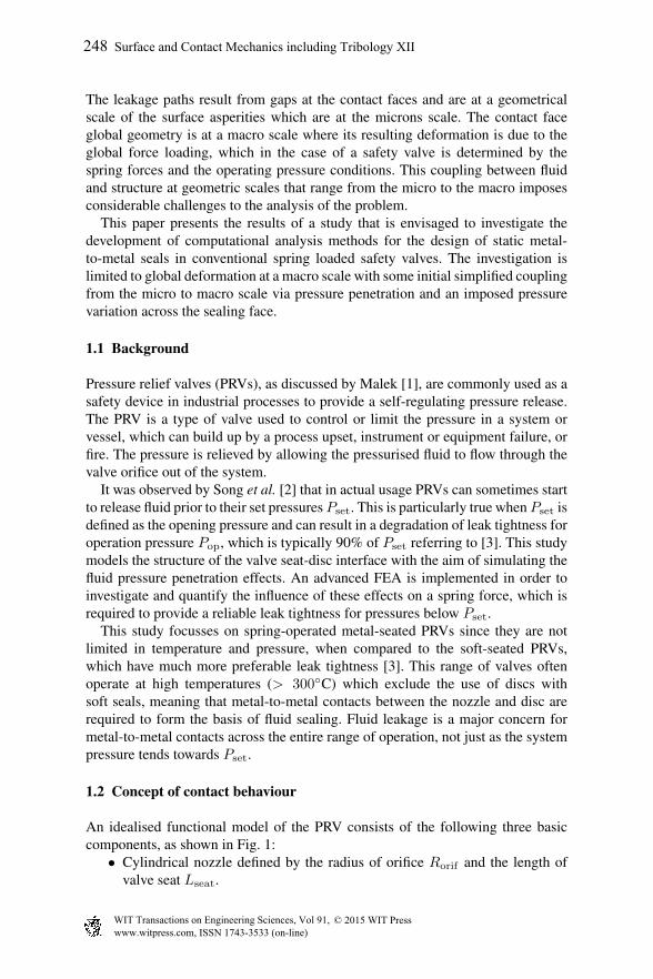
An idealised functional model of the PRV consists of the following three basiccomponents, as shown in Fig. 1:
• Cylindrical nozzle defined by the radius of orifice Rorif and the length ofvalve seat Lseat.
WIT Transactions on Engineering Sciences, Vol 91, www.witpress.com, ISSN 1743-3533 (on-line)
© 2015 WIT Press
248 Surface and Contact Mechanics including Tribology XII

Pma
macroscale
microscale
contact face
pre
ssu
rep
ressu
rep
ressu
re
Pmi
Pma macroscale
contact face
contact face
microscale
macro-microinteraction
Pmi(r)
Pma
Pma
Rorif
F
Lseat
Lseat
Lseat
Lseat
Pint(r)
}Forif
}
Fseat
a
b
c
Figure 1: Concept of macro-micro effects interaction in the contact area of metal-to-metal seal of a PRV.
• Relatively rigid disc, which keeps the nozzle closed during the normaloperation of the valve.
• Linear longitudinal spring, which is initially compressed and prevents liftingof the disc during normal operation.
The degree of spring compression is adjusted to fit the set pressure Pset. So thespring force is equal to the force produced by the internal pressure, when it reachesthe value of Pset, and applied to the disc surface corresponding to the orifice area.Since the system pressure Pma is below Pset during the normal operation, theorifice is kept tightly closed by the disc, providing a reliable seal through thedifference of forces applied to the disc. When the pressure builds up, a weakbalance of forces is achieved. Even a slight excess of Pset starts the disk lifting.This operation description is true only for an idealised (perfectly elastic) materialof the PRV. Since the real material, which is used for nozzle-disc pair, is quitefar from perfectly elastic, the following concept has been proposed and shown inFig. 1.
An internal edge of the valve seat is subjected to significant plastic deformationon the microscale, which is caused by the non-uniform contact conditions over thecontact face. Once the valve is subjected to operational conditions, the pressurisedfluid penetrates into the contact gap in the deformed contact face, as shownschematically on diagram in Fig. 1a. On the other hand, some limited degree ofleakage is always practically observed in the metal-seated valves within the wholerange of operation pressures. Since the contact is not perfectly tight, there is afluid pressure penetration (FPP) in the valve seat over the whole contact face,
WIT Transactions on Engineering Sciences, Vol 91, www.witpress.com, ISSN 1743-3533 (on-line)
© 2015 WIT Press
Surface and Contact Mechanics including Tribology XII 249
as shown on diagram in Fig. 1b. Therefore, the FPP effects are observed at twodifferent scales – macroscopic and microscopic. Since they both are assumed toexist in the same location, there should be an interaction between them. Predictionof the pressure profile over the contact face as a result of this interaction is a wayto assess an additional component of the force produced by this pressure profile.Thus, the spring force can be calculated more accurately as a sum of ‘orifice’ and‘seat’ components. An advanced FE-analysis using ANSYS is implemented forthe prediction of pressure profile as a result of macro-micro interaction as shownon diagram in Fig. 1c.
The proposed analysis concept is applied to an investigation of contactbehaviour in a typical spring-operated PRV with a medium size orifice ‘J’according to API Standard 526. An important fact is that the disc and nozzle areboth made of the austenitic stainless steel AISI 316N(L). It should be noted thatthe length of contact face of the valve seat in this PRV is relatively small whencompared to the diameter of orifice.
2 Material characterisation and modelling
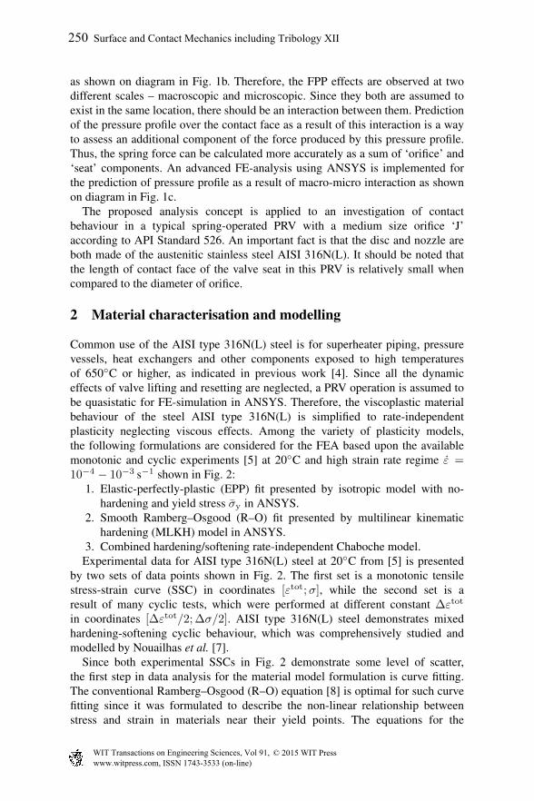
Common use of the AISI type 316N(L) steel is for superheater piping, pressurevessels, heat exchangers and other components exposed to high temperaturesof 650◦C or higher, as indicated in previous work [4]. Since all the dynamiceffects of valve lifting and resetting are neglected, a PRV operation is assumed tobe quasistatic for FE-simulation in ANSYS. Therefore, the viscoplastic materialbehaviour of the steel AISI type 316N(L) is simplified to rate-independentplasticity neglecting viscous effects. Among the variety of plasticity models,the following formulations are considered for the FEA based upon the availablemonotonic and cyclic experiments [5] at 20◦C and high strain rate regime ε =10−4 − 10−3 s−1 shown in Fig. 2:
1. Elastic-perfectly-plastic (EPP) fit presented by isotropic model with no-hardening and yield stress σy in ANSYS.
2. Smooth Ramberg–Osgood (R–O) fit presented by multilinear kinematichardening (MLKH) model in ANSYS.
3. Combined hardening/softening rate-independent Chaboche model.Experimental data for AISI type 316N(L) steel at 20◦C from [5] is presented
by two sets of data points shown in Fig. 2. The first set is a monotonic tensilestress-strain curve (SSC) in coordinates [εtot;σ], while the second set is aresult of many cyclic tests, which were performed at different constant ∆εtot
in coordinates [∆εtot/2; ∆σ/2]. AISI type 316N(L) steel demonstrates mixedhardening-softening cyclic behaviour, which was comprehensively studied andmodelled by Nouailhas et al. [7].
Since both experimental SSCs in Fig. 2 demonstrate some level of scatter,the first step in data analysis for the material model formulation is curve fitting.The conventional Ramberg–Osgood (R–O) equation [8] is optimal for such curvefitting since it was formulated to describe the non-linear relationship betweenstress and strain in materials near their yield points. The equations for the
WIT Transactions on Engineering Sciences, Vol 91, www.witpress.com, ISSN 1743-3533 (on-line)
© 2015 WIT Press
250 Surface and Contact Mechanics including Tribology XII

-700
-600
-500
-400
-300
-200
-100
0
100
200
300
400
500
600
700
-0.025 -0.02 -0.015 -0.01 -0.005 0 0.005 0.01 0.015 0.02 0.025 0.03
strain
stress (MPa)
monotonic tensile test
Δ /2 in cyclic tests (Δ = const)σ ε
FEA based on mono. curve
FEA based on cyclic curve
hardeninghardening
-0.03
softening
0.2%
EPP model with averaged σy
Figure 2: Experimental stress-strain curves [5] of AISI type 316N(L) steel at 20◦Cand fittings with the R–O (1) and MLKH models.
Table 1: Material parameters of AISI type 316N(L) steel at 20◦C corresponding tothe R–O (1) and EPP plasticity models.
TypeRamberg–Osgood EPP
B (MPa) β σy (MPa)
Monotonic 551.18 0.1075 282.6Cyclic 2379.07 0.3553 261.5Averaged — — 272.04
with E = 194 (GPa) and ν = 0.27 after [6].
WIT Transactions on Engineering Sciences, Vol 91, www.witpress.com, ISSN 1743-3533 (on-line)
© 2015 WIT Press
Surface and Contact Mechanics including Tribology XII 251
monotonic and cyclic SSCs are as follows:
εtot =σ
E+( σB
)1/β
and∆εtot
2=
∆σ
2E+
(∆σ
2B
)1/β
, (1)
where ∆εtot is the total strain range and ∆σ is the total stress range (MPa) for eachcyclic test respectively;B and β are material constants. The elastic properties usedin both R–O and elastic-perfectly-plastic (EPP) models are the Young’s modulusE in MPa and the Poisson’s ratio ν.
The elastic material properties at 20◦C are taken from [6] and given in Table 1.Using the defined value of E, the total strain εtot in the experimental curvesis decomposed into elastic and plastic strain. Then the plastic component εp ofstrain is fitted using the least squares method by the following relations, which arederived from the Eq. (1):
σ = B (εp)β and
∆σ
2= B
(∆εp
2
)β, (2)
where the resultant values of R–O material constants (B and β) are reported inTable 1. The R–O fits for monotonic and cyclic SSCs are then used to identify theconstants for the material models used for FEA.
Since the EPP model is not able to produce hardening, the multilinear kinematichardening (MLKH) model is applied to describe both types of curves [5]. Theresults of the MLKH model verification in ANSYS with a single cyclic FE-simulation of a uniaxial specimen at ∆εtot = 6% are shown in Fig. 2. It confirmsa very good match of the experiments [5] by the MLKH model with two differenttypes of material response.
3 Advanced structural FEA of the PRV operation
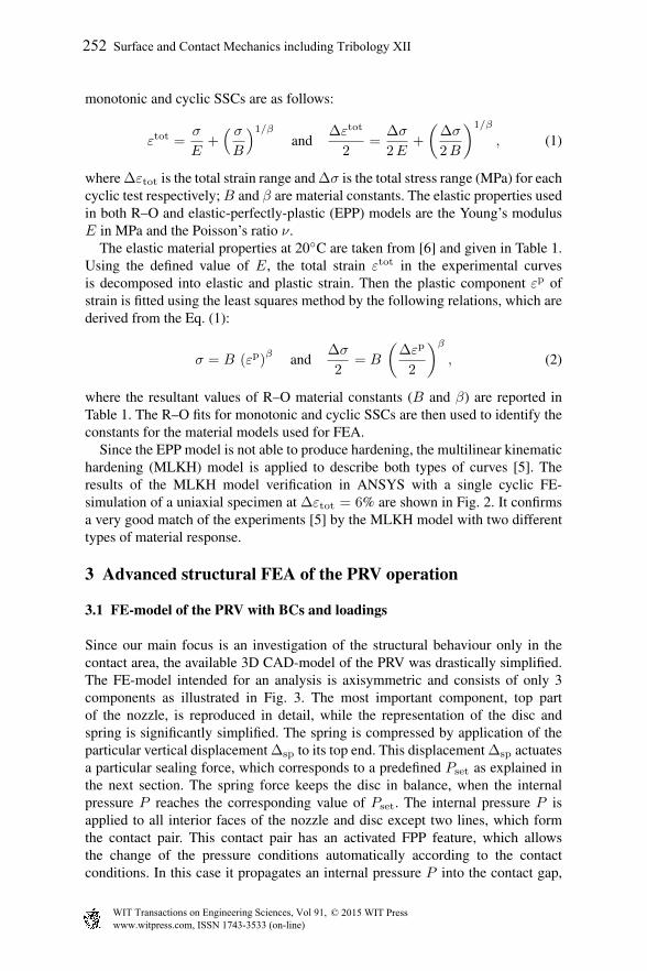
3.1 FE-model of the PRV with BCs and loadings
Since our main focus is an investigation of the structural behaviour only in thecontact area, the available 3D CAD-model of the PRV was drastically simplified.The FE-model intended for an analysis is axisymmetric and consists of only 3components as illustrated in Fig. 3. The most important component, top partof the nozzle, is reproduced in detail, while the representation of the disc andspring is significantly simplified. The spring is compressed by application of theparticular vertical displacement ∆sp to its top end. This displacement ∆sp actuatesa particular sealing force, which corresponds to a predefined Pset as explained inthe next section. The spring force keeps the disc in balance, when the internalpressure P reaches the corresponding value of Pset. The internal pressure P isapplied to all interior faces of the nozzle and disc except two lines, which formthe contact pair. This contact pair has an activated FPP feature, which allowsthe change of the pressure conditions automatically according to the contactconditions. In this case it propagates an internal pressure P into the contact gap,
WIT Transactions on Engineering Sciences, Vol 91, www.witpress.com, ISSN 1743-3533 (on-line)
© 2015 WIT Press
252 Surface and Contact Mechanics including Tribology XII
Δsp
P
80 FEs
FPP startpoint
}contact &target FEswith FPP
kinematicnodescoupling
macropressure
micropressure
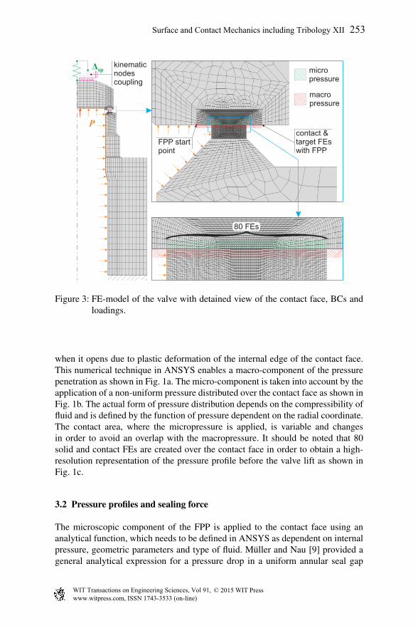
Figure 3: FE-model of the valve with detained view of the contact face, BCs andloadings.
when it opens due to plastic deformation of the internal edge of the contact face.This numerical technique in ANSYS enables a macro-component of the pressurepenetration as shown in Fig. 1a. The micro-component is taken into account by theapplication of a non-uniform pressure distributed over the contact face as shown inFig. 1b. The actual form of pressure distribution depends on the compressibility offluid and is defined by the function of pressure dependent on the radial coordinate.The contact area, where the micropressure is applied, is variable and changesin order to avoid an overlap with the macropressure. It should be noted that 80solid and contact FEs are created over the contact face in order to obtain a high-resolution representation of the pressure profile before the valve lift as shown inFig. 1c.
3.2 Pressure profiles and sealing force
The microscopic component of the FPP is applied to the contact face using ananalytical function, which needs to be defined in ANSYS as dependent on internalpressure, geometric parameters and type of fluid. Muller and Nau [9] provided ageneral analytical expression for a pressure drop in a uniform annular seal gap
WIT Transactions on Engineering Sciences, Vol 91, www.witpress.com, ISSN 1743-3533 (on-line)
© 2015 WIT Press
Surface and Contact Mechanics including Tribology XII 253
filled with a fluid as follows:
p(x) = p1
[1 −
(1 − γ2
) xL
]n, (3)
where L – length of a seal gap; p1 – internal pressure and p2 – external pressure;γ = p2/p1 – pressure ratio and n – power-law exponent, which is dependent onthe type of fluid – n = 0.5 for gas and n = 1 for liquid.
Equation (3) may be extended to the case of a plane contact gap in the valve.Since the profile of microscopic pressure distribution remains the same, themathematical form of pressure drop in the seal gap before valve opening is slightlychanged to
P (r) = Pset
[rout − r
rout − rfpp
]n, (4)
where Pset – set pressure corresponding to the balance of forces applied to thedisk, rout – outer radius of the contact area, rin – inner radius of the contact areaor radius of the orifice, rfpp – radius of fluid pressure penetration (FPP). It shouldbe noted that (rout < rfpp ≤ rin) if FPP is available, and rfpp = rin if FPP isunavailable.
Integrating Eq. (4) by r over the length of the valve seat (Lseat = rout − rin)from rin to rout, an average value of the pressure within the pressure profile isobtained in analytical form:
P =Pset
1 + n. (5)
Based upon the proposed concept, the total force, which needs to be actuated inthe spring during its preload in order to lift the valve at a set pressure Pset, consistsof the three components:
1. Orifice force or force produced by pressure Pset acting on the surface of thedisc corresponding to the area of the orifice:
For = Pset π r2in, (6)
2. Macro-fluid force, which is calculated assuming a stepped distribution ofpressure in the area of the macroscopic FPP:
Fma = Pset π(r2fpp − r2
in
), (7)
3. Micro-fluid force, which is calculated using the average pressure (5) over thearea of the microscopic FPP:
Fmi = P π(r2out − r2
fpp
). (8)
Thus, the total spring force includes an additional ‘seat’ component as:
Ftot = For + Fseat, where Fseat = Fma + Fmi. (9)
WIT Transactions on Engineering Sciences, Vol 91, www.witpress.com, ISSN 1743-3533 (on-line)
© 2015 WIT Press
254 Surface and Contact Mechanics including Tribology XII
FE-model setup:- FE size controls- spring setup- contact & FPP
2D valve geometry
Material character.:1. Material models2. Mechanical props
Input parameters:1. Type of fluid2. Spring stiffness3. Set pressure Ps
4. Operation pres.
5. Guess of the FPParea depth
P
D
o
FPP
Parametric relations:1. Total sealing force2. Spring parameters2. Spring displ. ∆sp
Solution setup:- BCs- Loadings- Solver
FPPareadepth
valvelifts?
yes no
–1FE+1FE
decre
ase
incre
ase
Guessing of the area formicro pressure application
convergedto no liftat ?Pset
no
Postprocessing:- contour plots- force vs displacement- applied pressuredistribution
solve
- quasistatic- large displ. on-
∆
3)
3 steps solution:
1) apply
2) 0
sp
→ P
P P
op
op set→
yes
input preprocess
Output:
P Dset ↔ FPP
DFPP
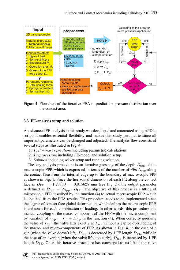
Figure 4: Flowchart of the iterative FEA to predict the pressure distribution overthe contact area.
3.3 FE-analysis setup and solution
An advanced FE-analysis in this study was developed and automated using APDL-script. It enables essential flexibility and makes this study parametric since allimportant parameters can be changed and adjusted. The analysis flow consists ofseveral steps as illustrated in Fig. 4:
1. Preliminary operations including parametric calculations.2. Preprocessing including FE-model and solution setup.3. Solution including solver setup and running solution.
The key analysis procedure is an iterative guessing of the depth Dfpp of themacroscopic FPP, which is expressed in terms of the number of FEs Nfpp alongthe contact face from the internal edge up to the boundary of macroscopic FPPas shown in Fig. 1. Since the horizontal dimension of each FE along the contactface is DFE = 1.25/80 = 0.015625 mm (see Fig. 3), the output parameteris defined as Dfpp = Nfpp · DFE. The objective of this process is a fitting ofmicroscopic FPP described by the function (4) to actual macroscopic FPP, whichis obtained from the FEA results. This procedure needs to be implemented sincethe degree of contact face global deformation, which defines the macroscopic FPP,is unknown for each combination of loading. In other words, this procedure is amanual coupling of the macro-component of the FPP with the micro-componentby variation of rfpp = rin + Dfpp in the function (4). When correctly guessingthe value of rfpp, the valve lifts exactly at Pset without a gap or overlapping ofthe macro- and micro-components of FPP. As shown in Fig. 4, in the case of agap (when the valve doesn’t lift), Dfpp is decreased by 1 FE length DFE, while inthe case of an overlap (when the valve lifts too early), Dfpp is increased by 1 FElength DFE. Once this iterative procedure has converged to no lift of the valve
WIT Transactions on Engineering Sciences, Vol 91, www.witpress.com, ISSN 1743-3533 (on-line)
© 2015 WIT Press
Surface and Contact Mechanics including Tribology XII 255

0
2
4
6
8
10
12
14
16
18
20
contact face length (mm)
set pre
ssure
(M
Pa)
contact face length (mm)set pre
ssure
(M
Pa)
0
2
4
6
8
10
12
14
16
18
20
18.6 MPa (cyclic)18.6 MPa (mono.)
15.3 MPa (cyclic)15.3 MPa (mono.)
10.2 MPa (cyclic)10.2 MPa (mono.)
5.1 MPa (cyclic)5.1 MPa (mono.)
1.98 MPa (cyclic)1.98 MPa (mono.)
mono. FEMcyclic FEM
a b
internal edge external edge internal edge external edge
Figure 5: FEA results with FPP and fluid pressure drop in contact area at differentset pressures for (a) liquid and (b) gas – markers denote the boundariesmacroscopic and microscopic FPP.
when P ≤ Pset, the main results are output in the form of values pair (Pset andcorresponding Dfpp).
4 Discussion and conclusions
The FEA have been performed for the wide range of Pset comprising 21 values(1.98–23.0 MPa). Each simulation was done for two different types of fluid (liquidor gas) and two different types of material response (monotonic or cyclic). Thesemake up a total of 84 FE-simulations, which were manually controlled to givea converged pressure profile on the contact face. Each variant of FEA required atleast 5 attempts to achieve a converged result. Therefore, about 500 FE-simulationshave been performed in this study.
Obtained results are shown in Fig. 5 in the form of dots and triangles for allvalues of Pset and in the form of pressure profiles over the contact face for 5standard values of Pset. The degree of macroscopic FPP increases non-linearlywith an increase of Pset for both types of fluids. However, the particular depthof global FPP Dfpp and corresponding length of effective contact area (Leff =Lseat−Dfpp) is quite different for liquid and gas. The other important effect shouldalso be noted that the effective contact length Leff drastically decreases with cyclicoperation of the valve.
The numerical results were fitted by analytical functions, which were used forthe formulation of relations for additional ‘seat’ component of the spring force.The number of finite elements (FEs) involved in FPP at the macroscale is fittedby a smoothing function. It is dependent on Pset and uses an approximation of the
WIT Transactions on Engineering Sciences, Vol 91, www.witpress.com, ISSN 1743-3533 (on-line)
© 2015 WIT Press
256 Surface and Contact Mechanics including Tribology XII
0
0.5
1
1.5
2
2.5
3
liquid FEA mono.
liquid FEA cycl.
liquid analytic
gas FEA mono.
gas FEA cycl.
gas analytic
“seat”
com
ponent of th
e s
pring forc
e (
kN
)
0 5 10 15 20 25
0
5
10
15
20
25
30
35
set pressure (MPa)devia
tion (
%)
2.5%
8.2%
9.1%
27%
3.4%~0.5%
18.6 MPa
7 MPa
liquid-gas (33.3%)
liquid FEA mono.
liquid FEA cycl.
gas FEA mono.
gas FEA cycl.
0 5 10 15 20 25
set pressure (MPa)
ab
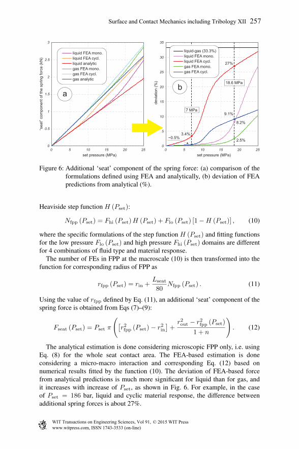
Figure 6: Additional ‘seat’ component of the spring force: (a) comparison of theformulations defined using FEA and analytically, (b) deviation of FEApredictions from analytical (%).
Heaviside step function H (Pset):
Nfpp (Pset) = Fhi (Pset)H (Pset) + Flo (Pset) [1 −H (Pset)] , (10)
where the specific formulations of the step function H (Pset) and fitting functionsfor the low pressure Flo (Pset) and high pressure Fhi (Pset) domains are differentfor 4 combinations of fluid type and material response.
The number of FEs in FPP at the macroscale (10) is then transformed into thefunction for corresponding radius of FPP as
rfpp (Pset) = rin +Lseat
80Nfpp (Pset) . (11)
Using the value of rfpp defined by Eq. (11), an additional ‘seat’ component of thespring force is obtained from Eqs (7)–(9):
Fseat (Pset) = Pset π
([r2fpp (Pset) − r2
in
]+r2out − r2
fpp (Pset)
1 + n
). (12)
The analytical estimation is done considering microscopic FPP only, i.e. usingEq. (8) for the whole seat contact area. The FEA-based estimation is doneconsidering a micro-macro interaction and corresponding Eq. (12) based onnumerical results fitted by the function (10). The deviation of FEA-based forcefrom analytical predictions is much more significant for liquid than for gas, andit increases with increase of Pset, as shown in Fig. 6. For example, in the caseof Pset = 186 bar, liquid and cyclic material response, the difference betweenadditional spring forces is about 27%.
WIT Transactions on Engineering Sciences, Vol 91, www.witpress.com, ISSN 1743-3533 (on-line)
© 2015 WIT Press
Surface and Contact Mechanics including Tribology XII 257
Referring to [3], metal-seated spring valves with operating pressures 90–95%of Pset do not stay tight for long and usually get damaged after a couple ofoperations. This fact was confirmed by the advanced FEA implemented in thisstudy using monotonic and cyclic plastic response. The effective contact area ofthe valve seat changes significantly during the cyclic operation of the valve. In thisregard, a spring force required to provide a leakage tightness of the valve needsto be adjusted correspondingly after each resetting. The results of the analysisdemonstrate that an alteration of the spring force during cyclic operation maybe over a quarter of its initial value. Analyses of the macro deformation of thevalve seat/disc under various pressures using quasistatic structural FEA with FPPtechnique revealed that:
1. Macro deformation is important and affects sealing area.2. Cyclic material response affects the structural behaviour.3. The type of fluid influences the contact pressure distribution.
References
[1] Malek, M.A., Pressure Relief Devices: ASME and API Code Simplified.McGraw-Hill: New York, USA, 2006.
[2] Song, X.-G., Park, Y.-C. & Park, J.-H., Blowdown prediction of a conventionalpressure relief valve with a simplified dynamic model. Math & CompModelling, 57(1–2), pp. 279–288, 2013.
[3] Hellemans, M., The Safety Relief Valve Handbook: Design and Use of ProcessSafety Valves to ASME and International Codes and Standards. Butterworth-Heinemann: Oxford, UK, 2009.
[4] Gorash, Y., Altenbach, H. & Lvov, G., Modelling of high-temperature inelasticbehaviour of the austenitic steel AISI type 316 using a continuum damagemechanics approach. Journal of Strain Analysis, 47(4), pp. 229–243, 2012.
[5] Chaboche, J.-L., Dang Van, K. & Cordier, G., Modelization of the strainmemory effect on the cyclic hardening of 316 stainless steel. Trans. 5th Int.Conf. on Structural Mechanics in Reactor Technology, IASMiRT: Berlin,Germany, number L11/3 in SMiRT5, pp. 1–10, 1979.
[6] Karditsas, P.J. & Baptiste, M.-J., Thermal and structural properties offusion related materials. ARIES Properties Archive: UKAEA FUS 294,Euratom/UKAEA Fusion Association, San Diego, 1995.
[7] Nouailhas, D., Cailletaud, G., Policella, H., Marquis, D., Dufailly, J., Lieurade,H.P., Ribes, A. & Bollinger, E., On the description of cyclic hardening andinitial cold working. Engineering Fracture Mechanics, 21(4), pp. 887–895,1985.
[8] Ramberg, W. & Osgood, W.R., Description of stress-strain curves by threeparameters. Technical Note no. 902, National Advisory Committee ForAeronautics, NASA, Washington DC, USA, 1943.
[9] Muller, H.K. & Nau, B.S., Fluid Sealing Technology: Principles andApplications. Marcel Dekker, Inc.: New York, USA, 1998.
WIT Transactions on Engineering Sciences, Vol 91, www.witpress.com, ISSN 1743-3533 (on-line)
© 2015 WIT Press
258 Surface and Contact Mechanics including Tribology XII