Process Improvement Understanding, Modelling and Improving the Software Process.

2009 SIMULIA Customer Conference 1
Modelling of an Improvement Device for a Tension Test Machine in Crippling Tests
Iván Lafuente* , José L. Alcaraz**, and Iñigo Ortiz de Zárate*
* Dpto. de Cálculo. Aernnova Engineering Solutions. 01510–Miñano, Alava (SPAIN) ** Dpto. Ing. Mecánica. Escuela Técnica Superior de Ingeniería de Bilbao. 48013–Bilbao (SPAIN)
Abstract: An analysis of the crippling test applied to thin profiles is considered in this paper by using a standard tension test machine. Crippling tests are compression tests leading to crush collapse. This kind of tests cannot be properly performed in the standard test machine because of an inefficient transmission of the compression load to the specimen. To accomplish a more accurate test an improvement device is designed and modelled. This proposed device consists of four symmetrically-arranged guides joining the two machine heads. The head rotation is thus avoided during the test and the compression load is transmitted to the profile without introducing bending effects through the heads. In order to show the advantage of the new design, the two cases (with and without the guides) have been analysed with Abaqus and compared one to another. The test results are also presented for the initial machine. The numerical model includes heads, potting, clamps and a C-shaped profile as specimen. This one is a carbon fibre composite modelled as an orthotropic elastic material. It results from the analysis that the proposed design provides more accurate values for the critical loads in the crippling test.
Keywords: Compression Tests, Crippling Tests, Composites.
1. Introduction
Thin profiles are commonly used in aerospace applications. In order to determine their compressive behaviour, the specimen is forced to a crushing process by compression load. This test is known as “crippling test” and is considered in this work.
When using a standard test machine (Instron model 4485), the test gives rise to important instabilities because of the introduction of bending besides compression into the specimen deformed shape. The machine heads lack the required stiffness for a reliable test.
A possible way to avoid the introduction of undesired bending is to design an implement to guide the parallel motion of the machine heads. This is proposed here by means of four symmetrically-arranged guides joining the two machine heads.

2009 SIMULIA Customer Conference 2
Load cell
Upper moving head
Upper moving plate
Specimen
Lower plate
Lower head
Clamps
Simulation of compression loaded composites has previously been considered (Ansótegui, 2008; Degenhardt, 2006). Similarly, damage in composites under compressive loadings have also been taken into account in other works (Chang, 1991).
Numerical simulation results for the initial machine and the machine with guides along with test results are presented and compared in this work. For the numerical computation the Abaqus finite elements code has been used and a material degradation model has been included. Firstly an analysis for the model without guides is performed and a suitable model is created after the adjustment to the test results. Then the improvement device is introduced in the model and results are compared with those from the machine without guides.
2. Model description
A CAD model performed with CATIA V5 for the test machine components is shown in Figure 1.
Figure 1. Test machine components.
The finite element model will consider the components between the two plates. The head stiffness and the contacts between the clamps and the specimen potting will also be taken into account.

2009 SIMULIA Customer Conference 3
Two models are implemented: one with guides and another without guides (see Figure 2).
Figure 2. Finite Element models: with guides (left) and without guides (right).
2.1 Part definition
a. Guides
Each guide is composed of 3420 hexahedral linear elements (C3D8 type). A finer mesh is used around the contact area, as shown in Figure 3. The guide material is a structural steel with an elastic modulus of 200 GPa and a Poisson ratio of 0,3.
Figure 3. Guide meshing.
Contact with lower plate
Contact with upper plate

2009 SIMULIA Customer Conference 4
b. Plates
Each plate is modelled by means of 3160 hexahedral linear elements. In order to avoid possible convergence problems in the guides contact zone, the number of elements around the holes is the same as in the outer layer of the guides ends. Plate material is steel with the same material properties as for the guides.
Figure 4. Plate meshing.
c. Specimen
A C-section or channel configuration specimen is used, modelled with 1653 shell elements (S4 type), as seen in Figure 5. Three different zones are defined, with a similar mesh size. The two profile ends form the first one to be embedded within the potting. The second one is the middle portion, where the main strain results will be obtained. Finally, it is considered the joint area between the two precedent zones.
Figure 5. Specimen meshing.
The elastic constants are shown in Table 1 and the admissible stress values in Table 2, for the specimen composite material (U.S. Dept. of Defense, 2002). YT and YC stand respectively for the tension and compression admissible stress along the direction normal to the fibres; XT and XC are

2009 SIMULIA Customer Conference 5
the admissible stresses along the fibre direction, and S12 is the admissible shear stress on the shell plane.
Table 1. Composite elastic constants. E11 (MPa) E22 (MPa) v12 G12 (MPa) G13 (MPa) G23 (MPa)
145000 8900 0,33 5600 5600 4480
Table 2. Composite strength values. YT (MPa) YC (MPa) XT (MPa) XC (MPa) S12 (MPa)
51 269 2414 972 120 A USDFLD subroutine has been used to take material degradation into account. The model follows the Puck failure theory applicable to composite materials (Puck, 1982, 1996). According to this theory mechanical properties are reduced to a 10% when failure occurs. Four different cases can be distinguished: one corresponding to the sound material and three to failure situations (matrix failure, fibre failure and matrix & fibre failure). Table 3 shows the four cases with their corresponding material constants.
Table 3. Composite mechanical properties degradation. Failure E11 (MPa) E22 (MPa) v12 G12 (MPa) G13 (MPa) G23 (MPa)
Sound 145000 8900 0,33 5600 5600 4480 Matrix failure 145000 890 0,033 560 5600 4480 Fibre failure 14500 8900 0,033 560 560 448 Matrix & Fibre failure 14500 890 0,033 560 560 448
d. Potting
The so-called potting is the component joined to the specimen ends to provide a good fastening between the thin profile and the clamps. The potting material is an epoxy resin with an elastic modulus of 5451 MPa and a Poisson ratio of 0,357. The potting mesh consists of 399 hexahedral linear elements (C3D8), as shown in Figure 6.
Figure 6. Potting meshing.

2009 SIMULIA Customer Conference 6
e. Clamps
The clamps have been modelled as rigid surfaces, since their deformation can be assumed negligible compared to that suffered by the potting or the specimen. Therefore few elements are required. Here 80 rigid elements (type R3D4) are considered in each clamp, as seen in Figure 7.
Figure 7. Clamp meshing.
f. Heads
Each machine head is modelled as a rigid surface. It consists of 55 rigid elements (type R3D4), as seen in Figure 8. The load is applied to the test by means of the controlled motion of this surface.
Figure 8. Head meshing.
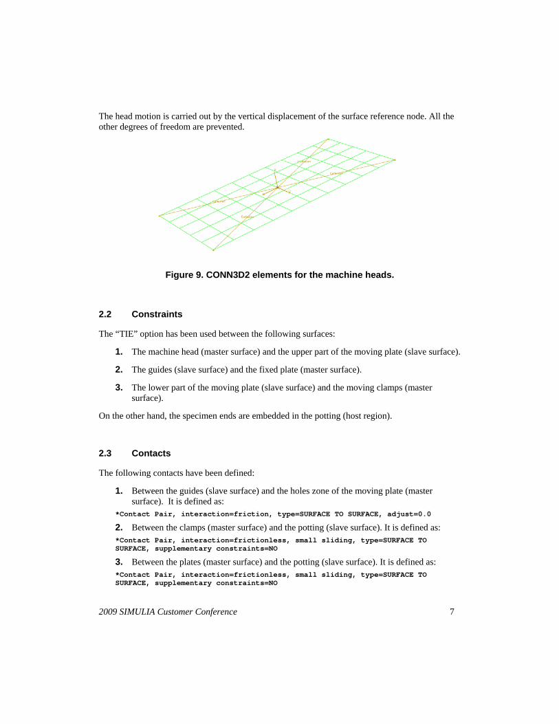
The head stiffness has been considered through four connector elements (type CONN3D2), each one connecting the surface middle point with a surface corner, as shown in Figure 9.
After some trial analyses, a stiffness value of 20 KN/mm is estimated and introduced in the computation for the three displacement directions.
2009 SIMULIA Customer Conference 7
The head motion is carried out by the vertical displacement of the surface reference node. All the other degrees of freedom are prevented.
Figure 9. CONN3D2 elements for the machine heads.
2.2 Constraints
The “TIE” option has been used between the following surfaces:
1. The machine head (master surface) and the upper part of the moving plate (slave surface).
2. The guides (slave surface) and the fixed plate (master surface).
3. The lower part of the moving plate (slave surface) and the moving clamps (master surface).
On the other hand, the specimen ends are embedded in the potting (host region).
2.3 Contacts
The following contacts have been defined:
1. Between the guides (slave surface) and the holes zone of the moving plate (master surface). It is defined as:
*Contact Pair, interaction=friction, type=SURFACE TO SURFACE, adjust=0.0
2. Between the clamps (master surface) and the potting (slave surface). It is defined as: *Contact Pair, interaction=frictionless, small sliding, type=SURFACE TO SURFACE, supplementary constraints=NO
3. Between the plates (master surface) and the potting (slave surface). It is defined as: *Contact Pair, interaction=frictionless, small sliding, type=SURFACE TO SURFACE, supplementary constraints=NO

2009 SIMULIA Customer Conference 8
2.4 Boundary conditions
There are three boundary conditions in the model:
1. The lower part of the fixed plate and the lower clamp are embedded.
2. The machine head is moved through the rigid surface displacement (simulating the load application).
3. The upper clamps do not rotate (remaining parallel to the plane 1-2).
2.5 Analysis type
Contact changes, geometrical instabilities, as well as material degradation are expected during the simulation. A non-linear analysis has accordingly been employed. The first buckling mode of the process is introduced as geometrical imperfection. A direct, Newton–Raphson integration method for the global stiffness matrix will be used in the analysis.
Figure 10 shows the effect of different time increments on the results. Below the crippling load, there is no influence of time incrementation, but after that point the best fitting corresponds to the smaller time increments. As the computational cost also increases, the time increment denoted by inc = 0.05 + 0.003125 + 0.00625 has been assumed for the final model.
Figure 10. Results comparison for different time increments.

2009 SIMULIA Customer Conference 9
3. Results
Figure 11 shows the load-displacement results for the machine test and the two numerical models, with and without guides.
Figure 11. Load-displacement results.
The initial slope is higher in the model with guides. This fact is a consequence of the higher stiffness of the model.
On the other hand, the specimen first instability is quite well captured in the plot, due in part to the introduction of the geometrical imperfection in the model.
The curve of the model without guides falls sharply once the instability limit has been reached. This points out the strong bending effect in this case.
Finally, Figure 11 shows that the results from the model with guides and from the test fit quite well.
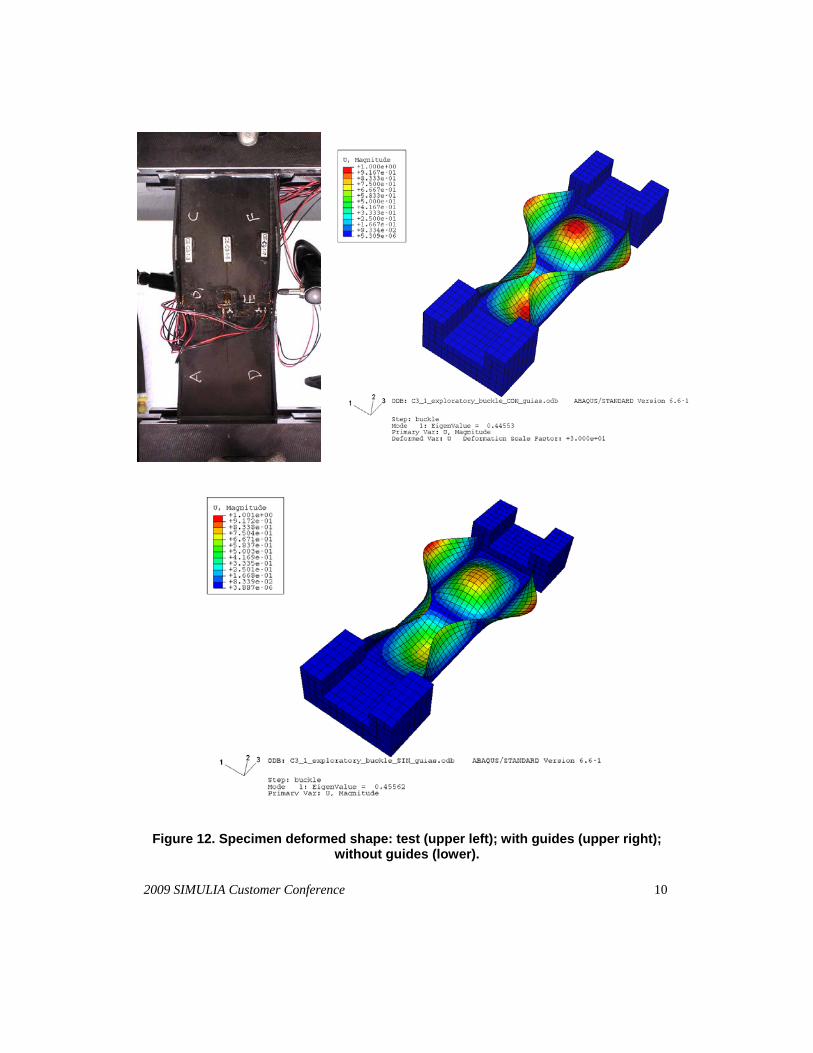
The deformed shape of the specimen is plotted in Figure 12 for the test and the models with guides (upper right) and without guides (lower). It is apparent that the deformation in the upper right figure is more symmetric that in the lower one.
2009 SIMULIA Customer Conference 10
Figure 12. Specimen deformed shape: test (upper left); with guides (upper right); without guides (lower).

2009 SIMULIA Customer Conference 11
Load-strain results have also been obtained by using 10 strain gages arranged at 5 back-to-back locations of the same cross-section, as shown in Figure 13. These load-strain results are very sensitive to the gage location and the deformed shape of the specimen. Nevertheless the numerical results agree reasonably well with the test results.
The linear part of the plots can be related to the bending effect in the model: as the slope dispersion increases there will be more instability because of the undesired bending effect. In an ideal compression test the specimen strains will provide the same slope at different readings across the section.
According to Figure 13, the test results involve the higher slope variation and accordingly more bending effect. Moreover the model with guides leads to strains with very small slope dispersion. This fact agrees with the higher initial stiffness obtained in Figure 11 for the two models and especially for the model with guides. As a consequence the load application in the model with guides is more efficiently conducted.
In order to quantify the improvement of the model with guides with reference to that without guides, a two-step procedure has been employed. Firstly, the fitting of the results from the model without guides to the test results will be checked in the linear part through the slope dispersion. Secondly, the model with guides will be compared with the model without guides and the improvement will be measured for the same results feature.
Figure 14 shows the similarity in the linear part between the test results and those from the model without guides. Gage number 1 for the test is invalidated because it seems to provide an erroneous measurement. This gage is located on one of the profile wings. The value is compared and corrected with the two gages located on the opposite wing.
By computing the highest difference between the two extreme plots (at the end of the linear part), a 3,6% difference between the test and the model without guides has been obtained, this difference considered small enough for our requirements.
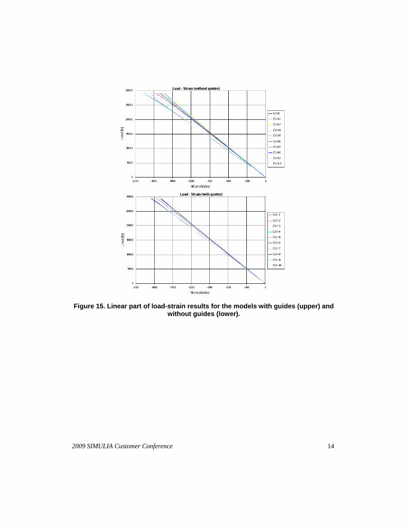
As mentioned before, the second step in this analysis is to compare the two models: with guides and without guides. Figure 15 shows the results and provides a 55% reduction in the maximum difference for the model with guides. This corroborates the improvement in the test performing conditions for the latter case.

2009 SIMULIA Customer Conference 12
Figure 13. Load-strain results.

2009 SIMULIA Customer Conference 13
Figure 14. Linear part of load-strain results for the test (upper) and the model without guides (lower).
2009 SIMULIA Customer Conference 14
Figure 15. Linear part of load-strain results for the models with guides (upper) and without guides (lower).

2009 SIMULIA Customer Conference 15
4. Conclusions
This paper has dealt with the crippling test of a C-section profile (channel configuration). By performing the test in a standard test machine, an undesired bending effect is obtained. For this reason, a modification is proposed implying the implementation of four guides between the upper and lower plates. The effect of this design improvement has been analysed in this work. The Abaqus code has proved to be useful in performing the analysis. A material degradation subroutine has been used for the specimen composite and a geometrical imperfection has also been introduced in the model.
The test results and those obtained from numerical models for a machine with or without guides have been presented and compared. From the analysis it comes out that the undesired bending effect and the subsequent instabilities during the test are prevented by using the model with guides. The application of the method to other sections or materials is quite straight-forward and will help to obtain crippling results.
5. References
1. Ansótegui J., I. Ortiz de Zarate, and F. Rebollo, “FEM simulation of potted ends on compression loaded graphite-epoxy test specimens”, 2nd Int. Conference on Buckling and Postbuckling behaviour of Composite Laminated Shell Structures, Sept. 2008.
2. Chang F. K., and L. B. Lessard, “Damage tolerance of laminated composites containing an open hole and subject to compressive loadings. Part I: Analysis”, Journal of Composite Materials, vol. 25, pp. 2-43, 1991.
3. Degenhardt R., R. Rolfes, R. Zimmermann, and K. Rohwer, “Improved material exploitation of composite airframe structures by accurate simulation of postbuckling and collapse” (COCOMAT project), Composite Structures, vol. 73, n. 2, 175-178, 2006.
4. Puck A., “Festigkeitsanalyse von Faser-Matrix-Laminaten”, Carl Hanser Verlag, München, 1996.
5. Puck A., and H. Schürmann, “Die Zug/Druck-Torsionsprüfung an rohrförmigen Probekörpern”, Kunstoffe, vol. 72, n. 9, pp. 554-561, 1982.
6. U.S. Department of Defense, “Composite materials handbook”. MIL-HDBK-17-3F. Volume III: Materials Usage, Design, and Analysis. 2002.