
Modelling of 3D Cadastral Systems - GDMC · Modelling of 3D Cadastral Systems Peter van Oosterom 1,...
14
Modelling of 3D Cadastral Systems Peter van Oosterom 1 , Jantien Stoter 2 and Christiaan Lemmen 2,3 1 OTB Research Institute for Housing, Urban and Mobility Studies, Delft University of Technology, Jaffalaan 9, 2628 BX Delft, The Netherlands, Tel +31 15 2786950, Fax +31 15 2782745 2 International Institute for Geo-Information Science and Earth Observation (ITC), Hengelosestraat 99, 7514 AE Enschede, The Netherlands, Tel. +31 53 4874523, Fax + 31 53 4874575. 3 Dutch Cadastre, Apeldoorn, P.O. Box 9046, 7300 GH Apeldoorn, The Netherlands, Tel. +31 55 5285695 [email protected] A standardized core cadastral domain model (CCDM), covering land registration and cadastre in a broad sense (multipurpose cadastre), will serve at least two important goals: 1. avoid reinventing and re-implementing the same functionality over and over again, but provide an extensible basis for efficient and effective cadastral system development based on a model driven architecture, and 2. enable involved parties, both within one country and between different countries, to communicate based on the shared ontology implied by the model. This paper will focus on the inclusion of 3D aspects within the core cadastral model. Two important components of the 3D Cadastre model are: 1. the ‘surface parcel partition’ based on a detailed elevation model and 2. the volume parcel and its representation. Technological solutions for both parts are not yet available in commercial Geo-ICT software and therefore solutions in a Geo-DBMS environment have been investigated, designed and developed . A number of countries in the world do already have legislation allowing the registration of volume parcels, sometimes even including detailed regulations for 3D survey plans. However, until today these are not yet integrated in the cadastral information system. 1. Introduction Until today most countries (or states or provinces) have developed their own cadastral system because there are supposed to be huge differences between different systems. It should be emphasised that a cadastral system entails a) land registration, b) the ‘administrative/legal component', and c) (geo referenced) cadastral mapping, the ‘spatial component'. There are systems that operate deed registration, other operate title registration, some systems are centralized, and others decentralized. Some systems are based on a general boundaries approach, others on fixed boundaries. Some cadastres have a fiscal background, others a legal one (Bogaerts and Zevenbergen, 2001). However, it is also obvious that because of differences in systems the implementation and system's maintenance of a cadastral system are not cheap, especially if one considers the ever-changing requirements. Also, the different implementations (foundations) of the cadastral systems do not make meaningful communication very easy, e.g. in an international context such as within Europe. Looking at it from a little distance one can observe that the systems are in principle the same: they are all based on the relationships between persons and land, via (property) rights and are in most countries influenced by developments in the Information and Communication Technology (ICT). The two main functions of every cadastral system are: 1. keeping the contents of this relationship up-to-date (based on legal transactions) and 2. providing information on this registration. Organisations are now increasingly confronted with rapid developments in the technology, a technology push: internet, (geo)-databases, modelling standards, open systems, GIS, as well as a growing demand for new services, a market pull: e-governance, sustainable development, electronic conveyance, integration of public data and systems. Cadastral modelling is considered as a basic tool facilitating appropriate system development and re-engineering and in addition it forms the basis for meaningful communication between different (parts of the) systems. Standardization is a well- known subject since the establishment of cadastral systems. Open markets, globalisation, and effective and efficient development and maintenance of flexible (generic) systems ask for further standardization. The initiative described in this paper will demonstrate how standards-based distributed networks of databases and information services can help consumers and citizens to access vital data, businesses to offer premium customer services, and governments to provide more effective service to citizens. In this paper we specifically focus on the 3D aspect of cadastral systems. Individualisation of property started originally with subdividing the surface into property units using 2D boundaries. For this reason the basic entity of current cadastral maps is the ‘parcel’, which makes the cadastral map a 2D map. To ensure completeness and consistency, 2D parcels may not overlap and gaps may not occur (forming a surface partition). Although parcels are represented in 2D, someone with a right to a parcel always has in general been entitled to a space in 3D, i.e. a right of ownership on a parcel relates to a space in 3D that can be used by the owner (it includes space above and below the parcel as well) and is not limited to just the surface parcel defined in 2D without any height or depth. If the right of ownership only applied to the surface, the use of the property would be impossible. Consequently, from a juridical point of view cadastral registration always has been 3D. The 2D approach of registration has been adequate for decades to give insight into traditional property situations, where it is clear which persons are entitled to
Transcript of Modelling of 3D Cadastral Systems - GDMC · Modelling of 3D Cadastral Systems Peter van Oosterom 1,...

Modelling of 3D Cadastral Systems
Peter van Oosterom 1, Jantien Stoter 2 and Christiaan Lemmen 2,3
1OTB Research Institute for Housing, Urban and Mobility Studies, Delft University of Technology, Jaffalaan 9, 2628 BX Delft, The Netherlands, Tel +31 15 2786950, Fax +31 15 2782745
2International Institute for Geo-Information Science and Earth Observation (ITC), Hengelosestraat 99, 7514 AE Enschede, The Netherlands, Tel. +31 53 4874523, Fax + 31 53 4874575.
3Dutch Cadastre, Apeldoorn, P.O. Box 9046, 7300 GH Apeldoorn, The Netherlands, Tel. +31 55 5285695 [email protected]
A standardized core cadastral domain model (CCDM), covering land registration and cadastre in a broad sense (multipurpose cadastre), will serve at least two important goals: 1. avoid reinventing and re-implementing the same functionality over and over again, but provide an extensible basis for efficient and effective cadastral system development based on a model driven architecture, and 2. enable involved parties, both within one country and between different countries, to communicate based on the shared ontology implied by the model. This paper will focus on the inclusion of 3D aspects within the core cadastral model. Two important components of the 3D Cadastre model are: 1. the ‘surface parcel partition’ based on a detailed elevation model and 2. the volume parcel and its representation. Technological solutions for both parts are not yet available in commercial Geo-ICT software and therefore solutions in a Geo-DBMS environment have been investigated, designed and developed . A number of countries in the world do already have legislation allowing the registration of volume parcels, sometimes even including detailed regulations for 3D survey plans. However, until today these are not yet integrated in the cadastral information system.
1. Introduction Until today most countries (or states or provinces) have developed their own cadastral system because there are supposed to be huge differences between different systems. It should be emphasised that a cadastral system entails a) land registration, b) the ‘administrative/legal component', and c) (geo referenced) cadastral mapping, the ‘spatial component'. There are systems that operate deed registration, other operate title registration, some systems are centralized, and others decentralized. Some systems are based on a general boundaries approach, others on fixed boundaries. Some cadastres have a fiscal background, others a legal one (Bogaerts and Zevenbergen, 2001). However, it is also obvious that because of differences in systems the implementation and system's maintenance of a cadastral system are not cheap, especially if one considers the ever-changing requirements. Also, the different implementations (foundations) of the cadastral systems do not make meaningful communication very easy, e.g. in an international context such as within Europe. Looking at it from a little distance one can observe that the systems are in principle the same: they are all based on the relationships between persons and land, via (property) rights and are in most countries influenced by developments in the Information and Communication Technology (ICT). The two main functions of every cadastral system are: 1. keeping the contents of this relationship up-to-date (based on legal transactions) and 2. providing information on this registration. Organisations are now increasingly confronted with rapid developments in the technology, a technology push: internet, (geo)-databases, modelling standards, open systems, GIS, as well as a growing demand for new services, a market pull: e-governance, sustainable development, electronic conveyance, integration of public data and systems. Cadastral modelling is considered as a basic tool facilitating appropriate system development and re-engineering and in addition it forms the basis for meaningful communication between different (parts of the) systems. Standardization is a well-known subject since the establishment of cadastral systems. Open markets, globalisation, and effective and efficient development and maintenance of flexible (generic) systems ask for further standardization. The initiative described in this paper will demonstrate how standards-based distributed networks of databases and information services can help consumers and citizens to access vital data, businesses to offer premium customer services, and governments to provide more effective service to citizens. In this paper we specifically focus on the 3D aspect of cadastral systems. Individualisation of property started originally with subdividing the surface into property units using 2D boundaries. For this reason the basic entity of current cadastral maps is the ‘parcel’, which makes the cadastral map a 2D map. To ensure completeness and consistency, 2D parcels may not overlap and gaps may not occur (forming a surface partition). Although parcels are represented in 2D, someone with a right to a parcel always has in general been entitled to a space in 3D, i.e. a right of ownership on a parcel relates to a space in 3D that can be used by the owner (it includes space above and below the parcel as well) and is not limited to just the surface parcel defined in 2D without any height or depth. If the right of ownership only applied to the surface, the use of the property would be impossible. Consequently, from a juridical point of view cadastral registration always has been 3D. The 2D approach of registration has been adequate for decades to give insight into traditional property situations, where it is clear which persons are entitled to

which parcels (including space above and below the parcel). However, the question can be posed if traditional cadastral registration, which is based on the concept of a 2D parcel, is also adequate for registering all kinds of situations that occur in the modern world. Pressure on land in urban areas and especially their business centres has led to overlapping and interlocking constructions. The creation of property rights to match these developments is available within existing legislation, however describing and depicting them in the cadastral registration poses a challenge. The challenge is how to register overlapping and interlocking constructions and how to register the property situations above and below the surface in a cadastral registration that registers information on 2D parcels. Although property has been located on top of each other for many years, it is only recently that the question has been raised as to whether cadastral registration should be extended into the third dimension. The growing interest for 3D cadastral registration is caused by a number of factors:
• a considerable increase in (private) property values; • the number of tunnels, cables and pipelines (water, electricity, sewage, telephone, gas, glass fibre data cables,
coax TV cables), underground parking places, shopping malls, buildings above roads/railways and other cases of multilevel buildings has grown considerably in the last forty years;
• an upcoming 3D approach in other domains, 3D GIS (Geographical Information Systems), 3D topographic data, 3D data collection (GPS, laser, surveying) 3D planning, which makes a 3D approach of cadastral registration technologically realisable.
The core cadastral domain model (CCDM) therefore supports 3D cadastral registration; besides the surface parcels (defined in 2D but implying 3D columns), the CCDM also recognizes true 3D-defined volume parcels as real estate objects; see Section 2. Two alternatives for 3D cadastre support, which do not introduce a new 3D volume parcel as real estate object (which requires also changes to the legislation) are presented in Section 3: a). Rights are associated with 3D RightObjects and b). Legal space of physical objects is registered. In both alternatives the parcels remain the only units on which rights or restrictions can be established, the other new introduced objects types should be considered additional in order to provide better insight into the 3D situation. However, the introduction of a full 3D cadastre remains the superior solution (but requires a change in legislation in most countries). Therefore the conceptual model of a full 3D cadastre is further analysed in Section 4, together with implementation issues of both the surface parcels (in 3D) and the volume parcels. A case study in Queensland, Australia is used as an illustration. Section 5 contains the conclusions. 2. Core Cadastral Domain Model (CCDM) Figure 1 shows the central part of the Core Cadastral Domain Model (CCDM) as was already presented at the FIG working week in April 2003, Paris (Lemmen, Van Oosterom 2003). It shows the Unified Modeling Language (UML) class diagram, which represents the result of the previous work. The relationship between real estate objects (e.g. parcels) and persons (sometimes called ‘subjects’) via rights is the foundation of every land administration. Besides rights, there can also be restrictions between the real estate objects and the persons. The figure shows that RightOrRestriction is an association class between the classes Person and RealEstateObject. Note that this an n-to-m relationship, with the conditions that every persons should at least be associated with one RealEstateObject and vice versa; every RealEstate object should be associated with at least one Person (indicated in the UML diagram with the multiplicity of ‘1..*’ at both ends of the association). The first refinement is the extension of the class RightOrRestrction to explicitly include Responsibilities as well. A restriction means that you have to allow someone to do something or that you have to refrain from doing something yourself. Responsibilities mean that one has to actively do something.
Figure 1: Core of the Cadastral Domain Model: Person, RightOrRestricton(OrResponsibility), RealEstateObject
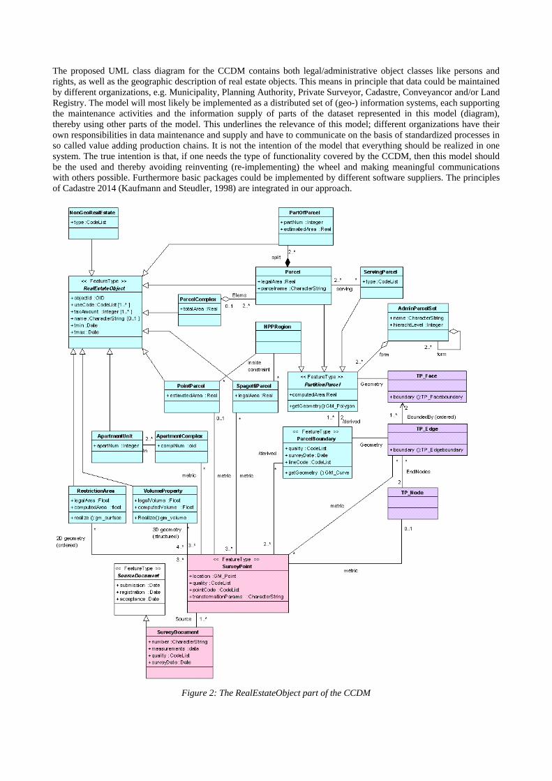
The proposed UML class diagram for the CCDM contains both legal/administrative object classes like persons and rights, as well as the geographic description of real estate objects. This means in principle that data could be maintained by different organizations, e.g. Municipality, Planning Authority, Private Surveyor, Cadastre, Conveyancor and/or Land Registry. The model will most likely be implemented as a distributed set of (geo-) information systems, each supporting the maintenance activities and the information supply of parts of the dataset represented in this model (diagram), thereby using other parts of the model. This underlines the relevance of this model; different organizations have their own responsibilities in data maintenance and supply and have to communicate on the basis of standardized processes in so called value adding production chains. It is not the intention of the model that everything should be realized in one system. The true intention is that, if one needs the type of functionality covered by the CCDM, then this model should be the used and thereby avoiding reinventing (re-implementing) the wheel and making meaningful communications with others possible. Furthermore basic packages could be implemented by different software suppliers. The principles of Cadastre 2014 (Kaufmann and Steudler, 1998) are integrated in our approach.
Figure 2: The RealEstateObject part of the CCDM

Because of the high pressure on the use of space, more and more situations occur which can best be modelled in three dimensions. Normally a (2D) Parcel represents the whole 3D column from the center of the earth, through the surface out into the sky. Explicit 3D VolumeProperties ‘carve out’ a part of this space in favour of another Person (the buyer of a 3D VolumeProperty). It is possible that one VolumeProperty overlaps with many Parcels (again this can be obtained via spatial overlay). VolumeProperties are modelled without external topology, but with internal topology by referencing several times to the same SurveyPoint, when this is shared between the different faces of a polyhedron, which is the geometry type that represents the 3D spatial properties of VolumeProperties. VolumeProperties should not overlap in 3D space. However, their projection in 2D space may overlap. It is expected that it will not happen often that VolumeProperties will share faces with other explicit VolumePropties (as is the case in 2D with the PartitionParcels). Might this assumption turn out to be wrong, then a 3D topological structured model should be introduced. Discussion on alternative ‘3D cadastral models’ can be found in section 3. The Cadastral Domain Model is based on already accepted and available standards on geometry and topology in 2D published by ISO and OGC (ISO, 1999a, 1999b, OpenGIS Consortium 1998, 2000a, 2000b, 2000c and 2000d). Geometry is based on SurveyPoints (mostly after geo referencing, depending on data collection mode: tape, total station, GPS, etc) and is associated with the classes tp_node (topology node) and tp_edge (topology edge) to describe intermediate ‘shapes’ points between nodes, metrically based on SurveyPoints. The association between a ParcelBoundary and SurveyDocument is derived via the classes SurveyPoint, tp_node and tp_edge. Parcels have a 2D geometric description. A Parcel corresponds one-to-one to the tp_face in a topological structure (as defined by ISO TC 211 and OpenGIS Consortium). Concerning 3D, implementation standards on both geometry and topology need to be specified. 3. Three dimensional alternatives/extensions Current cadastral registration systems, based on 2D topological and geometrically described parcels, have shown limitations in providing insight in (the 2D and 3D) location of 3D constructions (e.g. pipelines, tunnels, building complexes) and in the vertical dimension (depth and height) of rights established for 3D constructions (Stoter and Ploeger, 2002; Stoter and Ploeger, 2003). In the previous section the VolumeProperty was introduced, but this requires a significant change in the legislation in most countries. Therefore in this section some alternatives (with less legal impact and based on the well known concept of the 2D parcel) for 3D situations are presented together with their UML class diagrams. As 3D legal volumes, 3D constructions themselves cannot be queried in current cadastral registration systems. For example it is not possible to perform a query such as 'who is the owner of this tunnel?'. To overcome these limitations, the 3D aspect should be incorporated in the core cadastral data model. Two alternatives to the VolumeProperty of the core cadastral data model have been introduced in the 3D cadastre research (Stoter and Ploeger, 2002; Stoter and Ploeger, 2003; Stoter, 2004). These will be described in this section. 3.1 Registration of the 3D extension of rights The first alternative is just a simple extension of the central part of the model as was shown in figure 1: the introduction of a 3D right-object. The UML class diagram of 3D right-objects is shown in figure 3. For every right that is established on a parcel and that concerns a complex situation (one parcel is used by more than one person) a 3D right-object is maintained. This contains the 3D representation of the space to where the right applies, which is also maintained in the DBMS. The 3D right-object is established on a parcel for a 3D construction (Stoter and Ploeger, 2002). The 2D extent of a 3D right-object is the actual parcel-boundary. The upper and lower limits of the 3D right-object are the upper and lower limits of the space to where the right applies (Stoter and Ploeger, 2002). The 3D right-object gives insight into the vertical dimension of the rights established. For example when a railway tunnel crosses a parcel and a right of superficies is established on the parcel, the 3D right-object is the 3D description of the space to where the right applies. This example is illustrated in figure 4. For this example new (fictive) parcel boundaries were created in order to avoid that parts of parcels that do not overlap with the tunnel are affected with a right of superficies. With the 3D right-objects it is possible to see that the rights are established for an underground construction, also the depth and height of the

construction is visible, which is not visible on conventional cadastral maps.
Figure 3: UML class diagram of 3D right-objects
One 3D right-object can be associated with more than one right, e.g. if a tunnel is held by two subjects. One 3D right-object can have a reference to more than one physical object. For example when two tunnels held by one subject cross a parcel and only one right is established for the two tunnels. All 3D right-objects belonging to one physical object can be found since they refer to the same 3D physical object. The factual ownership of a volume of space can be found by tracing the subject(s) that has/have the right that is associated with the 3D right-object. The data model needs some adjustment compared to the current cadastral model, but the principle of the 2D parcels as basic objects remains the same. The registration of a 3D right-object will not take place if only one subject has the complete right on a parcel. For the tunnel the registration of 3D right-objects will not take place, when the Ministry of Transport and Public Works owns the intersecting parcel. This leads to 'gaps' in the 3D registration. This is illustrated in figure 4 on the right.
Figure 4: 3D right-objects representing the 3D extent of rights established on 2D parcels for a railway tunnel owned by
the Ministry. Left: all the parcels are encumbered by right of superficies, new parcels are created for all intersecting parcels. Right: Newly subdivided parcels are encumbered with a right of superficies (with 3D representation), other
newly subdivided parcels are now owned by the Ministry while other (complete) parcels owned by the Ministry are not subdivided .
3.2 Legal space of object is registered How to know the actual location of the tunnel and to avoid the 'gaps' in the registration? A solution is the registration of the complete construction itself, as is shown for the railway tunnel in figure 5. This would be the most optimal solution to register the legal space of the 3D physical object. The legal space is the space that is relevant for the cadastre (bounding envelope of the object), which is usually larger than the physical extent of the object itself (for example including a safety zone). Note that this solution does not introduce the possibility to register 3D physical objects as real-estate objects. The cadastral registration of the legal status of real estate is still based on 2D parcels.

Figure 5: Registration of the legal space of the railway tunnel. The dashed line is the projection of the tunnel on the surface. Note that the parcels are not divided into smaller parcels.
The UML class diagram of this registration is shown in figure 6. Apart from parcels (cadastral objects), the legal space of 3D physical objects are also registered. The holder of the 3D physical object is a subject with a right on the intersecting parcels established for the 3D physical object (factual ownership, which is not the same as the juridical ownership). This can be right of superficies, but also complete ownership. In general the holder of a 3D physical object is the person or organization who is responsible for the 3D physical object, and uses the object as if he were the owner. Rights and limited rights are still registered on parcels. The only right that a person can get on a 3D physical object is that he can become the holder of this object. Therefore, a 3D physical object is not a subset of cadastral objects: 3D physical objects are maintained in addition to 2D parcels. The juridical relationship between the legal space of the 3D object and the intersecting parcel(s) is stored implicitly, because the holder of a 3D physical object is maintained. This is the same (non-natural) person who has a right on the intersecting parcels. The solution of registering the legal space of 3D objects compensates many limitations of current cadastral registration. The intersecting parcels still need a right referring to a 3D construction, but the parcels need not to be divided into smaller parcels. The spatial relationships between parcels and the (legal space of the) 3D physical object can be maintained with spatial functions in the DBMS.
Figure 6: UML class diagram of 3D physical objects 4. 3D Cadastre implementation aspects The term ‘3D cadastre’ can be interpreted in many ways ranging from a full 3D cadastre supporting volume parcels, to traditional cadastres in which limited information is maintained on 3D situations. In our research we have distinguished three different conceptual models for a 3D cadastre (with several alternatives):
- Full 3D cadastre (see section 2), in which persons can explicitly be entitled to volumes: o Alternative 1: combination of (traditional) infinite parcel columns and volume parcels o Alternative 2: only parcels are supported that are bounded in three dimensions (volume parcels)
- Hybrid cadastre, in which persons are entitled to volumes by giving them rights on the intersecting parcels (see section 3):
o Alternative 1: registration of 2D parcels in all cases of real property registration and additional registration of 3D legal space in the case of 3D property units within one parcel, using a bottom and top height level of the space to which rights apply (see subsection 3.1)
o Alternative 2: registration of 2D parcels in all cases of real property registration and additional registration of the legal space of physical objects in 3D space (see subsections 3.2)
- 3D administrative tags/warnings linked to parcels in current cadastral registration (not discussed earlier, but this is the current situation in many countries)

The last solution (3D administrative tags and warnings) has proven to be a good starting point (it is current practice in many cadastral registrations). However a fundamental lack of this approach is that both spatial and non-spatial information is not integrated in the cadastral registration: the 3D information is stored in separated files. The hybrid approach has shown to be a good alternative for cadastres that are still very much land (surface) oriented, i.e. right to real property can only be established by encumbering the intersecting surface parcels with limited rights and restrictions. Therefore one basic principle is not addressed. Since the legal status is still registered by means of land parcels, querying the legal status in 3D still means collecting information on the legal status of the intersecting surface parcels. Although parcels are traditionally represented in 2D, someone with a right to a parcel always has been entitled to a space in 3D. This led to no disputes as long as only one person was entitled to a land parcel since the traditional cadastre was capable of reflecting such property situations. However, in recent times stratified property is common practice, and in many countries multifunctional use of space is official planning policy. Also the way humans relate to land has changed drastically (value of private property has increased considerably). Today’s cadastral registration should therefore reflect the true principle of property rights that entitle persons to volumes and not to just areas. The ultimate ambition for 3D cadastral registration should be a full 3D cadastre in which it is possible to entitle persons both to unconstrained parcel columns that are defined by boundaries on the surface and to bounded amounts of space (volume parcels). In a full 3D cadastre, 3D space (universe) is subdivided into volumes partitioning the 3D space. The legal basis, real estate transaction protocols and the cadastral registration should support the establishment and conveyance of rights that explicitly entitle persons to volumes (i.e. 3D rights). The 2D cadastral map does not lay down any restrictions on 3D rights: 3D rights are not related to the surface configuration (as is the case in the two other conceptual models of a 3D cadastre). Real estate objects can be defined in 3D. Rights and restrictions can be related to volumes. Relationships between two volume parcels may be necessary to take care of for example the accessibility of a volume parcels which is not directly connected to the surface. In subsection 4.1 the two alternatives for a full 3D Cadastre a compared and it is concluded that alternative 1 (combination of infinite parcels columns and volume parcels) is the best solution. Next subsection 4.2 discusses a model for integrated storage the surface parcels and the surface height (based on a refined constrained TIN structure). The model for representing the volume parcels (based on a polyhedron data type) is discussed in subsection 4.3. Finally, this section is concluded with a case study in which the different parts of the solution are used: surface parcels and volume parcels (subsection 4.4). 4.1 Full 3D Cadastre alternatives In the full 3D cadastre, alternative 2, the only real estate object that is recognised by the cadastre is a volume parcel (bounded in all dimensions). These volume parcels form a complete partition of the domain in 3D space. In this solution it is no longer possible to entitle persons to infinite parcel columns, defined by surface parcel boundaries, but only to well-defined (and totally bounded), surveyed volumes. In this alternative cadastral registration of the whole country is converted into 3D. The question can be posed if a full 3D cadastre that only supports volume parcels is realistic for cadastral registrations that have a long history and already contain a lot of information that is related to 2D parcels which still suffice in many cases. It requires a total renewal of the cadastre, also in 2D situations: traditional 2D situations (parcels with no other owners in the 3D column) also need to be changed. Therefore, in our research we focused on the more realistic alternative of a full 3D cadastre, which combines volume parcels with parcels that are defined by parcel boundaries on the surface (but which correspond to the infinite parcel columns in 3D space). The full 3D cadastre that combines parcels defined on the surface (corresponding to infinite 3D parcel columns) and volume parcels starts with the currently registered parcels (that still suffice in many 2D situations). In addition to the infinite parcel columns, volume parcels are distinguished. Part of the UML class diagram of this solution was already shown in figure 2. The collection of the 2.5D surfaces of parcels (parcels draped over a height surface) explicitly covers the whole surface (without overlaps and gaps), that is, a complete surface partition. This is further examined in subsection 4.2. This is a very important concept in cadastral registration in order to avoid inconsistencies. A Parcel implies the whole 3D column above and below the surface or what is left after volume parcels have been subtracted from the parcel column. The geometry of the VolumeParcel defines a bounded space in 3D (and the possible realisation of this is discussed in subsection 4.3). Consequently a complete space partition is defined by the (infinite) Parcel columns and the VolumeParcels. One VolumeParcel can be established crossing several parcels and several volume parcels can be established above or below one parcel. Important constraints for the full 3D cadastre are:
1. projection of Parcels that are defined on the surface should form a full partition of the 2.5D earth surface; 2. VolumeParcels may not intersect other VolumeParcels (in 3D).
To be able to register the Parcels and VolumeParcels in the cadastral registration, all real estate objects must have a survey document, which should make clear to what space the real estate object refers. The 3D information in these survey documents can then be integrated in the cadastral geographical data set, which will be a mix of 2.5D objects (surface parcels and restriction areas) and 3D objects.

4.2 Elevation model based surface Parcels In the 3D cadastre research the conceptual models of a 3D cadastre, as described in section 2, are translated into prototype implementations. Therefore the required technology has been studied and, if necessary, existing technology has been extended with self-implemented extensions (Stoter, 2004). The DBMS is considered as the core in the prototype architecture, since DBMS is the fundamental part in the new generation GIS architecture. In this section we focus on the first technical aspect of the proposed full 3D cadastral model when combining the volume parcels with elevation model based surface parcels: the 2D parcels need to be represented in 2.5D, draped over a height surface. In section 4 another important technical aspect of our model is discussed: how true 3D volume objects can be represented in the DBMS. For the surface parcels (2.5D representations), we studied the most appropriate data structure. TINs (Triangular Irregular Network) have proven to be a suitable structure for representing height surfaces. Therefore we focused our research on representing the height surface of parcels in a TIN structure. For this research four different types of TINs were generated, all representing surface height models based on point heights obtained from laser altimetry, and of which the last three also include 2D parcels. In all cases the data is stored in one single DBMS. In the future a distributed DBMS structure may be possible within the Geo-Information Infrastructure (GII). An integrated view, based on two different databases (as the different data sets are maintained by different organisations in different databases) may be feasible from the technical perspective. There is a close relationship between Digital Elevation Models (DEMs, 2.5D), based on for example raw laser-altimetry point data, and the topographic objects or features embedded in the terrain. 2D objects, from another independent source, such as a cadastral or topographic map, can explicitly be incorporated as part of the TIN structure, which is representing a height surface (Lenk, 2001; Stoter and Gorte, 2003). In this case the TIN structure is based on both 2D objects and point heights. The data structure of the surface partition of 2D objects is embedded within the TIN. Within this data structure, the 2D objects are identifiable in the TIN and are obtainable from the TIN, as a selection of triangles which yield 2.5D surfaces of individual 2D objects. This is the topic of this research. For the study described here, the following two data sets have been used (see figure 7): laser height data and (2D) cadastral parcel. A number of different triangulation methods are tested as basis for the TIN of the integrated height/parcel model: Unconstrained TIN, Constrained TIN, Conforming TIN, and Refined constrained TIN (Stoter et al., 2004). After some analyses, the most promising solution, the refined constrained TIN, was selected.

Figure 7: Data sets used in this research; top: elevation (dark = low, light = high), middle: cadastral parcels, bottom:
integrated 2D surface parcels and height points in a conforming TIN (note: observation point from other side) 4.3 Volume objects In the previous subsection it was described how to derive and store elevation model based surface parcels. In this subsection it is described how the second main element of our conceptual model, true 3D volume objects can be supported, including validation and spatial functions in 3D, in a DBMS. The present Geo-DBMSs do not support 3D primitives. The absence of a real 3D volume primitive in the Geo-DBMSs, however, creates major problems. Geo-DBMSs do not recognise 3D spatial volume objects, because they do not have a 3D volume primitive to model them. This results in DBMS functions that do not work properly (e.g. there is no validation for the 3D volume object as a whole and functions only work when these objects are projected, because the third dimension is ignored). In our research we implemented a polyhedron data type in the DBMS (Stoter and Van Oosterom, 2002; Arens et al., 2003) as an extension to the geometry model of Oracle Spatial (Oracle, 2002). The (2D) geometry model of Oracle is (more or less) similar to the OGC (ISO TC211) model. The polyhedron is the equivalent of a polygon, but in 3D. It is made up of several flat faces that enclose a volume. An advantage is that one polyhedron equals one factual object. A polyhedron has exactly one exterior boundary (set of faces). For every internal ‘cavity’ (hollow) the polyhedron has also exactly one interior boundary. In total a polyhedron has therefore one ore more boundaries (shells). Because a polyhedron can have holes in the exterior and interior boundary (set of faces), it can model many types of objects. The 3D primitive was implemented in a geometrical model with internal topology. The polyhedron was realised by storing the vertices explicitly as (x,y,z) and describing the arrangement of these vertices in the faces of the polyhedron. This yielded a hierarchical boundary representation (Aguilera, 2001; Zlatanova, 2000). Note that edges were not stored explicitly in this model. Managing topological structures between objects (e.g. sharing common faces) is not within the scope of the polyhedron primitive. However, internal topology within one object was maintained since the vertices for one object would be stored only once: faces were defined by internal references to nodes and nodes were shared by faces. The implementation details and examples can be found in (Arens et al., 2003). The SQL ‘INSERT INTO’ command is used to insert a polyhedron (cube) in the table (see Figure 8), which show the syntax when encoding a polyhedron primitive: INSERT INTO polyhedron_table (id, geometry) VALUES (1, -- id of object mdsys.sdo_geometry(3002, -- geometry type: 3D line (polyhedron faked for spatial index) NULL, NULL, mdsys.sdo_elem_info_array( -- array with triplets:
-- starting offset, element type, interpretation code 1,2,1, -- first triplet is line for spatial indexing, next six faces 25,0,1006, 29,0,1006, 33,0,1006, 37,0,1006, 41,0,1006, 45,0,1006), mdsys.sdo_ordinate_array( 1,1,0, 1,3,0, 3,3,0, 3,1,0, -- coordinates of the nodes 1-4 1,1,2, 1,3,2, 3,3,2, 3,1,2, -- coordinates of the nodes 5-8 1,2,3,4, 8,7,6,5, 1,4,8,5, -- bottom, top, front face (node references) 2,6,7,3, 1,5,6,2, 4,3,7,8) -- back, left, right face (node references) ));

Figure 8: Polyhedron (cube) defined by its six faces It is important that the spatial data be checked when it is inserted or changed in the DBMS. Checking the geometry of the spatial objects is called validation. Validation is necessary to ensure that the objects can be correctly manipulated, e.g. it is impossible to compute the volume of a cube when the top face is omitted; this would merely be an open box. Validating may seem fairly easy to humans, but a computer needs a large set of rules to check spatial data. Validation of the values of a data type (such as the polyhedron) is lowest, most fundamental, level of a spatial integrity constraint in the DBMS. To allow for checking the spatial data, it is important to give an accurate definition of the 3D primitive. A polyhedron is a bounded subset of 3D coordinate space, which is enclosed by a finite set of flat polygons in such a way that each edge of a polygon is shared by exactly one other polygon (Aguilera, 2001). A valid polyhedron bounds a single volume, which means that from every point (also on the boundary), every other point (also on the boundary) can be reached via the interior. The implemented validation function and some of the 3D functions have a tolerance value as input parameter. For example, the flat faces of a polyhedron are flat surfaces within a certain tolerance, as the points that make up the polygon can be slightly outside the flat plane, because of the geodetic measuring methods (Stoter and Salzmann, 2003; Stoter and Van Oosterom, 2002; Teunissen and Van Oosterom, 1988) and the finite representation of coordinates in a digital computer. To solve this problem a close-to-zero tolerance value was introduced. It is important that this value is not zero, as this would introduce errors in the functions if there were any deviations in floating point computations. It should not be too large either; otherwise invalid objects would be accepted as valid. A good value for the tolerance is the standard deviation of the geodetic measurements. The standard functions in most current Geo-DBMSs (including Oracle Spatial), ignore the third dimension, that is the 3D spatial objects are projected onto 2D coordinate space. For example, the area of a face that is standing up (vertical face) is zero, because its 2D projection is a line. To offer realistic functionality, some of the most common functions were implemented in 3D (for 0D up to 3D primitives):
• Unary function/program to insert data: Creating data from 3D multi-polygons and VRML. • Binary functions that return a Boolean: Point-in-polyhedron and intersection tests. • Unary functions that return a scalar: Area, perimeter and volume. • Binary functions that return a scalar: Distance between centroids. • Unary functions that return a simple geometry: Bounding box, centroid, 2D footprint and transformation
functions. • Binary functions that return a simple geometry: Line segment representing the distance between centroids.
4.4 Example from Queensland, Australia In order to evaluate the developed model and concepts a case study with real data has been conducted. The cadastral registration in Queensland is used here to illustrate in more detail the characteristics of a land registration that is already able to define parcels with a bounded volume. Queensland was selected from the other countries because for a number of years it already has detailed regulations for 3D survey plans and many examples are available from the Public Register (and it also has a complete digital 2D cadastral map). 3D cadastral issues in Queensland have been studied in collaboration with the Queensland Government, Department of Natural Resources, Mines and Energy (NRME). Volumetric parcels in the registration of Queensland, Autralia. According to the Land Title Act of Queensland (Queensland, 2003), a standard parcel (defined in 2D, but implying the 3D column) is a lot (or a collection of lots) which are unlimited in height and depth. Apart from these 'unrestricted' parcels, also Volumetric parcels are possible since 1997: parcels that are fully limited by bounding surfaces and are therefore independent of the 2D boundaries of the surface parcels. A case study from practice will be used to illustrate the establishment of volumetric parcels in Queensland: the establishment of 3D property units for the Gabba Cricket stadium in Brisbane. This stadium overlaps two streets: Vulture Street in the north and Stanley Street in the south (see figure 9).

Figure 9: Overview of Gabba Stadium overhanging Stanley Street in the south and Vulture Street in the north, Brisbane, Australia.
The 3D geometries can be incorporated in a cadastral geographical dataset that contains surface parcels represented in 2.5D in order to get a 3D overview of the complete situation. For this purpose a conforming TIN (Triangular Irregular Network) was generated that incorporated the surface partition of the cadastral base map (see section 3). The result is shown in figure 10.
Figure 10: Visualisation of 3D geometries of volumetric parcels together with the 2.5D cadastral base map.
5. Conclusion A core cadastral data model should serve at least two purposes:
1. Enable effective and efficient implementation of flexible (and generic) cadastral information systems based on a model driven architecture (as argued in this paper), and
2. Provide the ‘common ground’ for data exchange between different systems in the cadastral domain. The later one is a very important motivator to develop a core cadastral data model, which could be used in an international context; e.g. the EULIS project and the OGC (ISO TC211) activities such as ‘Property and Land Information Initiative’. It has always been the intention of the FIG core cadastral domain model (CCDM) to be compliant with both OGC and ISO TC211 standards (including the geometry and topology). In order to adhere to the ISO standard a model has to adhere to certain modelling rules (ISO19109) and the spatial types as defined in (ISO 19107) have to be used. Other relevant parts of the standard are about temporal modelling and geodetic coding. One of the advantages of modelling in UML is that it gives the possibility to generate an exchange format for the data in a standardised way. The GML3 standard (ISO 19136) describes how to translate an UML model to an GML Applications Schema (Portele, 2004). The foundation of the new CCDM is a 3D spatio-temporal parcel (actually four dimensions) with possible fuzzy boundaries. This does not mean that every cadastral system should have four dimensional fuzzy
parcels, but the model gives the overall framework. The actual systems are in a certain sense ’special cases’ of this general model; a number of examples of systems fitting in the CCDM:
• a traditional 2D parcel based system (with exact boundaries) • the system extended with 3D VolumeProperties • a 2D system but with temporal rights, actually the RealEstateObjects do have fixed geometry, but the right,
restrictions or responsibilities do change over time (could be in according to some kind of repeating pattern). • a 2D system with well defined parcels, but extended (in certain areas) with more fuzzy types of parcels
(SpagettiParcels and PointParcels) The new version of the model is intended to be a kind of interoperable implementation specification version of Cadastre 2014 (which is at a more abstract level). Being at an implementation level, it will guarantee that different systems adhering to this specification of the CCDM will be interoperable. This paper focused on modelling the 3D aspect of a Cadastral registration and the most prosing model (full 3D cadastre based on infinite parcel columns and volume parcels) was further investigated. The full 3D cadastre offers many improvements compared to traditional cadastral registrations:
• The real situation is no longer projected on the surface, i.e. volumetric parcels are not dominated by the parcel pattern on the surface.
• Persons can be entitled to space in a transparent way instead of establishing property rights on intersecting parcels to establish the legal status above and below the surface.
• The space is precisely described in a 3D survey document, which offers a uniform way of defining 3D property units.
The full 3D cadastre also offers improvements in countries and states that already establish 3D property units unrelated to the surface:
• The information from the 3D survey document can be used to insert the volume parcels in a topological structure and in geometrical primitives in the DBMS.
• The volume parcels can be viewed interactively. • The geometry of volume parcels can be checked, e.g. are the faces planar, is the volume closed, are there no
self-intersections? • The 3D situation can be (spatially) queried in the DBMS (e.g. do volume parcels intersect?). • The volume parcels can be visualised in an integrated view with a 2.5D representation of the parcels that are
defined by parcel boundaries on the surface. • The volume parcels and the 2.5D surface parcels can be queried in the DBMS, e.g. is the volume parcel
located above or below the surface, or does it intersect the surface? In this article we presented the 3D cadastre model that showed the best potential for the long-term future based on the requirements for cadastral registration: a full 3D cadastre that supports both infinite parcel columns defined by 2D surface parcels and volume parcels. The advantage of this model is that it has a strong link to the current 2D registration (parcels represented with parcel boundaries are still supported) while it also is possible to establish volume parcels which are no longer related to the surface. For the representation of parcels in this model, a height surface of parcels is needed. The integrated model of parcels and point heights was also described in this article. Several TINs were created and evaluated. The refined constrained TIN showed the best potential. In the future the representation of the integrated TIN should be implemented as an integrated view (in the DBMS sense) on the two data sets maintained as independent and distributed sources and not as a physical permanent integration. The second technological development was the selection, design and realisation of a 3D volume primitive within the geo-DBMS, a polyhedron data type, which is used to represent the (completely bounded) volume parcel. Acknowledgements We express our gratitude to the Netherlands’ Kadaster for the cooperation and the support of this research. We thank Rod Thompson (of the Queensland Government, Department of Natural Resources and Mines) for providing us with the different data sets needed for the Queensland case study (DTM, parcels, survey documents, land administration information)/ We thank our former MSc-thesis students Calin Arens and Friso Penninga for their efforts in the development of respectively the 3D polyhedron data type and the TIN based parcel surface models. Finally, we thank our partners in the GDMC (Geo Database Management Center), Oracle, Bentley and ESRI, again for making their software available. This publication is the result of the research programme 'Sustainable Urban Areas' (SUA) carried out by Delft University of Technology. References Aguilera, A., 1998. Orthogonal polyhedra: study and application. Ph.D. Dissertation, Universitat Politècnica de
Catalunya, Barcelona, Spain, 216 pp. Arens, C., J.E. Stoter, and P.J.M. van Oosterom, 2003. Modelling 3D spatial objects in a GeoDBMS using a 3D
primitive. In Proceedings AGILE 2003, Lyon, France, April 2003.

Boagearts, T. and Zevenbergen, J., 2001, 'Cadastral Systems - Alternatives', in: ‘Computers, Environment and Urban Systems’, Theme Issue ‘Cadastral Systems’, p. 325-337, Volume 25, number 4-5, 2001, Elsevier Science, New York.
ISO TC 211/WG 2, 1999a, ‘Geographic information - Spatial schema’, Technical Report second draft of ISO 19107 (15046-7), International Organization for Standardization, November 1999.
ISO TC 211/WG 3, 1999b, ‘Geographic information - Meta data’. Technical Report draft of ISO 19115 (15046-15), International Organization for Standardization, June 1999.
ISO19107 Geographic information – Spatial schema), Geneva, Switzerland. ISO ISO19109 Geographic information – Rules for application schema), Geneva, Switzerland. ISO ISO19136 Geographic information – Geography Markup Language (2004), Geneva, Switzerland. ISO Kaufmann, Jürg and Steudler, Daniel, 1998, ‘Cadastre 2014, A Vision for a Future Cadastral System, FIG, July 1998,
http://www.swisstopo.ch/fig-wg71/cad2014.htm Lenk, U., 2001, Strategies for integrating height information and 2D GIS data. In Joint OEEPE/ISPRS workshop: From
2D to 3D, establishment and maintenance of national core spatial databases, Hannover, Germany, October 2001. Lemmen, Christiaan and Oosterom, Peter van, 2003, ‘Further Progress in the Development of a Core Cadastral Domain
Model’, FIG Working Week, Paris, France April 2003. To be published at FIG website and www.oicrf.org Lemmen, C., P. van der Molen, P. van Oosterom, H. Ploeger, W. Quak, J. Stoter, and J. Zevenbergen, (2003b). A
modular standard for the Cadastral Domain, Digital Earth 2003 - Information Resources for Global Sustainability The 3rd International Symposium on Digital Earth, 21-15 September 2003, Brno, Czech Republic
Oosterom, van, Peter and Lemmen Christiaan, 2002a, ‘Impact Analysis of Recent Geo-ICT developments on Cadastral Systems’, FIG XXII Congres, Washington DC, USA, April 2002 www.fig.net/figtree/pub/fig_2002/Js13/JS13_vanoosterom_lemmen.pdf
Oosterom, van, Peter and Lemmen Christiaan, 2002b, 'Towards a Standard for the Cadastral Domain: Proposal to establish a Core Cadastral Data Model', COST Workshop ‘Towards a Cadastral Core Domain Model’, Delft, The Netherlands, 2002, http://www.i4.auc.dk/costg9/
OpenGIS Consortium, Inc. 1998, ‘OpenGIS simple features specification for SQL’, Technical Report Revision 1.0. OpenGIS Consortium, Inc, 2000a, ‘OpenGIS catalog interface implementation specification’ Technical Report version
1.1 (00-034), OGC, Draft. OpenGIS Consortium, Inc., 2000b: ‘OpenGIS grid coverage specification’, Technical Report Revision 0.04 (00-019r),
OGC. OpenGIS Consortium, Inc., 2000c: ‘OpenGIS recommendation - Geography Markup Language (GML)’ Technical
Report version 1.0 (00-029), OGC. OpenGIS Consortium, Inc., 2000d: ‘OpenGIS web map server interface implementation specification’, Technical
Report reversion 1.0.0 (00-028), OGC. ORACLE, 2002, Oracle spatial user’s guide and reference release 9.0.1 part number a88805-01. Technical report,
ORACLE, June 2002. Portele, C. (2004), Mapping UML to GML Application Schemas.
URL: http://www.interactive-instruments.de/ugas/ShapeChange.pdf Queensland Government, 2003, Land Title Regulation, 1994, Land Title Act 1994, Reprinted as in force on 1 July
2003. Stoter, J.E. and H.D. Ploeger, 2002, Multiple use of space: current practice and development of a 3D cadastre. In: E.M.
Fendel, K. Jones, R. Laurini and M. Rumor (eds.), Proceedings of UDMS ’02 23rd Urban Data Management Symposium, ’30 Years of UDMS, Looking Back, Looking Forward (Prague, Czech Republic, 1-4 October 2002), Prague, pp. I.1-I.16. CDrom.
Stoter, J.E. and P.J.M. van Oosterom, 2002, Incorporating 3D geo-objects into a 2D Geo-DBMS. In Proceedings FIG, ACSM/ASPRS, Washington D.C. USA, April 2002.
Stoter, J.E. and B. Gorte, 2003, Height in the cadastre, integrating point heights and parcel boundaries. In Proceedings FIG Working Week, Paris, France, April 2003.
Stoter, J.E. and H.D. Ploeger, 2003, Registration of 3D objects crossing parcel boundaries, FIG Working week 2003, April, Paris, France.
Stoter, J.E., Salzmann, M.A., 2003. Where do cadastral needs and technical possibilities meet? In: Cadastral Systems III, 3D Cadastres. In: P.J.M. van Oosterom and C.H.J. Lemmen (eds.); Computers, Environment and Urban Systems (CEUS), July 2003, Volume 27 no. 4, pp. 395-410. ISSN: 0198-9715.
Stoter, J.E., F. Penninga and P.J.M. van Oosterom, 2004, Generalization of integrated terrain elevation and 2D object models, in proceedings SDH 2004, augustus 2004, Leicester, UK.
Stoter, J.E., 2004, 3D Cadastre, PhD thesis, TU Delft, 344 pp. Teunissen, W.J.M., Van Oosterom, P.J.M., 1988. The creation and display of arbitrary polyhedra in HIRASP.
Technical Report, Number: 88-20, University of Leiden, the Netherlands. Zlatanova, S., 2000, 3D GIS for urban development. Ph.D. Dissertation, ITC, Publication 69, Enschede, the
Netherlands, 222 pp.