Anna Savage Report JAQU Air Quality Methodology Modelling ...
Modelling
Methodology
Status: Draft
Version/release: Planned as 2.0
Revision: Planned as A
Date: April 27th, 2009
ebIX Modelling Methodology 2
C O N T E N T
1 INTRODUCTION ..................................................................................................................................... 5
1.1 ABOUT THIS DOCUMENT ...................................................................................................................... 5 1.2 NEW IN VERSION 2.0 ............................................................................................................................ 5 1.3 OBJECTIVE ........................................................................................................................................... 5 1.4 WHY METHODOLOGY .......................................................................................................................... 5 1.5 ETC, EBIX TECHNICAL COMMITTEE ................................................................................................... 6 1.6 REFERENCES ........................................................................................................................................ 6 1.7 CHANGE LOG ....................................................................................................................................... 7
2 OVERVIEW OF THE EBIX METHODOLOGY .................................................................................. 8
2.1 INTRODUCTION TO THE EBIX MODELLING METHODOLOGY ................................................................ 8 2.2 FROM MODEL TO BUSINESS DOCUMENT .............................................................................................. 8 2.3 COMBINING COMMON ELEMENTS ........................................................................................................ 8 2.4 ROOM FOR NATIONAL STANDARDS...................................................................................................... 9
3 MODELLING WITHIN EBIX .............................................................................................................. 10
3.1 THE STRUCTURE OF A BUSINESS COLLABORATION MODEL ............................................................... 10 3.2 BUSINESS REQUIREMENTS VIEW ....................................................................................................... 12
3.2.1 Business Domain View .............................................................................................................. 12 3.2.2 Business Entity View .................................................................................................................. 13 3.2.3 Business Partner View ............................................................................................................... 15
3.3 BUSINESS CHOREOGRAPHY VIEW ..................................................................................................... 15 3.3.1 Business Transaction View ........................................................................................................ 16 3.3.2 Business Collaboration View ..................................................................................................... 18 3.3.3 Business Realization View ......................................................................................................... 18
3.4 BUSINESS INFORMATION VIEW ......................................................................................................... 19
4 UMM ACKNOWLEDGEMENT AND PROCESS BEHAVIOUR PRINCIPLES ........................... 21
4.1 ACKNOWLEDGEMENTS ...................................................................................................................... 21 4.1.1 Time to Acknowledge Receipt (Time expression) ...................................................................... 21 4.1.2 Time to Acknowledge Processing (Time expression) ................................................................ 21
4.2 BUSINESS TRANSACTION ................................................................................................................... 22 4.2.1 Business Transaction Type (Enumeration) ................................................................................ 22 4.2.2 Secure Transport (Boolean) ...................................................................................................... 22
4.3 (BUSINESS ACTION (ABSTRACT) ........................................................................................................ 22 4.3.1 Authorization (Boolean) ............................................................................................................ 23 4.3.2 Non Repudiation of Receipt (Boolean) ...................................................................................... 23 4.3.3 Non Repudiation (Boolean) ....................................................................................................... 23 4.3.4 Intelligible Check (Boolean) ...................................................................................................... 23
4.4 PROCESS BEHAVIOUR RELATED TO REQUESTING BUSINESS ACTION (ABSTRACT).............................. 23 4.4.1 Time to Respond (Time expression) ........................................................................................... 23 4.4.2 Retry Count (Integer)................................................................................................................. 24
4.5 PROCESS BEHAVIOUR RELATED TO INFORMATION PIN (ABSTRACT) .................................................. 24 4.5.1 Confidential (Boolean) .............................................................................................................. 24 4.5.2 Tamper Proof (Boolean) ............................................................................................................ 24 4.5.3 Authenticated (Boolean) ............................................................................................................ 24
5 VERSIONING ......................................................................................................................................... 25
5.1 VERSIONING OF XML SCHEMAS ........................................................................................................ 25 5.1.1 Major Versions .......................................................................................................................... 25 5.1.2 Minor Versions .......................................................................................................................... 25
5.2 VERSIONING OF UMM MODELS......................................................................................................... 26

ebIX Modelling Methodology 3
6 SUBMISSIONS TO UN/CEFACT ......................................................................................................... 27
7 EBIX TRANSFORMATION RULES ................................................................................................... 28
7.1 BUSINESS DOCUMENT TYPE ............................................................................................................... 28 7.2 DEPENDENCY MATRIX ....................................................................................................................... 29 7.3 BUSINESS DOCUMENT SET ................................................................................................................ 29 7.4 HOW TO COMBINE BOTTOM UP MODELLING AND REUSABLE ELEMENTS? ......................................... 31 7.5 RELATIONS BETWEEN VERSIONED MODELLING ELEMENTS ............................................................... 32
8 SYNTAX SPECIFIC DOCUMENTS .................................................................................................... 33
8.1 INTRODUCTION .................................................................................................................................. 33 8.2 CHANNEL REQUIREMENTS ................................................................................................................. 33
8.2.1 Choreography ............................................................................................................................ 33 8.3 SYNTAX MAPPING .............................................................................................................................. 34
8.3.1 XML ........................................................................................................................................... 34 8.3.2 EDIFACT ................................................................................................................................... 34
9 TABLE OF FIGURES ............................................................................................................................ 37
APPENDIX A EBIX PROJECTS............................................................................................................ 38
A.1 THE EBIX MODELLING PROJECT OUTLINE ......................................................................................... 39 A.2 MILESTONE REQUIREMENTS .............................................................................................................. 40 A.2.1 MILESTONE 1. PROJECT APPROVED FOR DEVELOPMENT ............................................................... 40 A.2.2 MILESTONE 2: SCOPE DEFINED ...................................................................................................... 41 A.2.3 MILESTONE 3: BUSINESS PROCESS DEFINED .................................................................................. 42 A.2.4 MILESTONE 4: INFORMATION REQUIREMENTS DEFINED ............................................................... 42 A.2.5 MILESTONE 5: BUSINESS COLLABORATION MODEL AND TRANSLATION GUIDES APPROVED ........ 43
APPENDIX B EBIX MAGICDRAW CC/UMM PROFILE ................................................................ 44
APPENDIX C DEFINITIONS AND GLOSSARY ................................................................................ 45
APPENDIX D INTRODUCTION TO UN/CEFACT MODELLING METHODOLOGY (UMM) .. 48
D.1 INTRODUCTION TO UMM .................................................................................................................. 48 D.2 BUSINESS REQUIREMENTS VIEW ....................................................................................................... 48 D.3 BUSINESS PARTNER VIEW ................................................................................................................. 49 D.4 BUSINESS ENTITY VIEW .................................................................................................................... 50 D.4.1 BUSINESS ENTITY STATES .............................................................................................................. 50 D.4.2 BUSINESS DATA VIEWS ................................................................................................................. 50 D.5 BUSINESS DOMAIN VIEW................................................................................................................... 50 D.6 BUSINESS CHOREOGRAPHY VIEW, .................................................................................................... 52 D.7 BUSINESS TRANSACTION VIEW ......................................................................................................... 52 D.7.1 STATES ........................................................................................................................................... 54 D.8 BUSINESS COLLABORATION VIEW .................................................................................................... 55 D.9 BUSINESS REALIZATION VIEW .......................................................................................................... 58 D.10 BUSINESS INFORMATION VIEW ......................................................................................................... 59 D.11 PRIMLIBRARY .................................................................................................................................. 60 D.12 ENUMLIBRARY................................................................................................................................. 60 D.13 CDTLIBRARY .................................................................................................................................... 60 D.14 QDTLIBRARY .................................................................................................................................... 60 D.15 CCLIBRARY ....................................................................................................................................... 60 D.16 BIELIBRARY ...................................................................................................................................... 61 D.17 DOCLIBRARY .................................................................................................................................... 61
APPENDIX E INTRODUCTION TO UML .......................................................................................... 62
ebIX Modelling Methodology 4
E.1 TERMS ................................................................................................................................................ 62 E.2 USECASES AND USECASE DIAGRAMS ............................................................................................... 63 E.2.1 USECASE........................................................................................................................................ 63 E.2.2 ACTOR ........................................................................................................................................... 64 E.2.3 EXTEND RELATIONSHIP ................................................................................................................. 64 E.2.3.1 ASSOCIATION ................................................................................................................................. 64 E.2.3.2 GENERALISATION .......................................................................................................................... 65 E.2.3.3 EXTEND RELATIONSHIP ................................................................................................................. 65 E.2.3.4 INCLUDE RELATIONSHIP ................................................................................................................ 66 E.3 ACTIONS, ACTIVITIES AND ACTIVITY DIAGRAMS ............................................................................. 67 E.3.1 ACTIVITIES ..................................................................................................................................... 67 E.3.2 ACTIONS ........................................................................................................................................ 68 E.3.3 OUTPUTPIN .................................................................................................................................... 68 E.3.4 ACTIONINPUTPIN ........................................................................................................................... 68 E.3.5 CALLBEHAVIORACTION ................................................................................................................ 70 E.4 CLASSES AND CLASS DIAGRAM ......................................................................................................... 71 E.4.1 CLASSES ......................................................................................................................................... 71 E.4.1.1 DATA TYPES ................................................................................................................................... 71 E.4.1.2 ENUMERATION ............................................................................................................................... 71 E.4.1.3 ENUMERATIONLITERAL ................................................................................................................. 72 E.4.1.4 TYPES ............................................................................................................................................. 72 E.4.2 GRAPHIC PATHS ............................................................................................................................. 72 E.4.2.1 ASSOCIATIONS ............................................................................................................................... 72 E.4.2.2 ASSOCIATION CLASS ..................................................................................................................... 73 E.4.2.3 MULTIPLICITY ELEMENT ............................................................................................................... 74 E.4.2.4 DEPENDENCY ................................................................................................................................. 74 E.4.2.5 GENERALIZATION .......................................................................................................................... 75 E.4.3 REALIZATION ................................................................................................................................. 76 E.4.4 UN/CEFACT RULES FOR MESSAGE DIAGRAMS ............................................................................ 76 E.5 STATES ............................................................................................................................................... 78 E.5.1 STATEMACHINE ............................................................................................................................. 78 E.5.2 PROTOCOL STATE MACHINE .......................................................................................................... 78 E.5.3 OBJECTNODE ................................................................................................................................. 79

ebIX Modelling Methodology 5
1 Introduction
1.1 About this document
The ebIX methodology is written mainly as a guide for ebIX projects and working groups, to help them in
their work. The methodology describes items such as how to do modelling according to ebIX rules, how to
make changes to models and business documents, etc.
1.2 New in version 2.0
Main changes from previous version:
• The ebIX Methodology is upgraded to follow the UN/CEFCAT Modelling Methodology version 2
(UMM), which is a complete recast of the previous version 1.
• The methodology outline in chapter Appendix A is updated to be in line with UMM 2.0.
• The extract from UMM is updated to version 2.0 and moved to Appendix D.
• Chapter 3, Modelling within ebIX is completely rewritten and includes among others examples of the
UML structure for CuS (and partly EMD).
• The extract from UML, Appendix E, is updated to version 2.1.2.
• The term Business information model is replaced with the term Business collaboration model in most
of the places used.
• The chapter containing CC information has been removed. The information (CC/BIE definitions) can
be found in Appendix C, Definitions and glossary.
• The chapter that contained Layout of ebIX documents has been removed. The layout will be added to
new chapters related to BRSs and RSMs.
1.3 Objective
A deregulated European energy market consists of several different business areas operated by a number of
parties with different roles. Each of these business areas has their own business experts with an in-depth
knowledge of the business processes and information flows within their area. Making common electronic data
exchange standards for these different business areas, involving different business experts, requires a common
methodology to assure that standards are made in a harmonised way.
The objective of ebIX is to define appropriate electronic data interchange standards for the different business
processes. In order to come to stable and coherent interchange standards, precise modelling in a syntax
independent way is needed. Accordingly, this has led to the development of a methodology, which defines the
rules for how to make ebIX business collaboration models and related technical documents for specification of
the exchange of electronic documents. The methodology is based on the UMM (UN/CEFACT Modelling
Methodology) and UML (Unified Modelling Language).
The objective of this document is to give an introduction to basic standards and other documents that are
relevant for the ebIX work. This includes the different UN/CEFACT standards, such as UMM, UPCC, UCM
and NDR, but also other documents such as the harmonised role model from ebIX, EFET and ETSO.
The audience for the document is mainly modelling experts participating in ebIX Technical Committee
(ETC), but parts of it, such as the description of the UMM Business Requirements View, may be useful for
business people participating in the development of business models.
1.4 ebIX requirements for the methodology
Given the objective described above we have reasons to decide on a methodology consisting of:
• Model independent of syntax and derive syntax dependent information exchanges from these models.
• Reuse common objects (information elements).
• Allow for national extensions and customisation.
ebIX Modelling Methodology 6
• Fit the ebIX models and information exchanges into the broader UN/CEFACT standards.
This implies:
• use UML for object oriented modelling
• taking CCTS (Core Components Technical Specification) as source of reusable information elements
• adopting UMM as the basis for the ebIX methodology
• adopting MDA (Model Driven Architecture) for deriving syntax dependent structures
1.5 ETC, ebIX Technical Committee
The ebIX methodology is maintained by ETC. If there is comments or suggestions to the methodology please
contact any member of ebIX/ETC.
For comments to the document, please contact the ebIX® secretary at [email protected].
1.6 References
[1] UN/CEFACT Unified Modelling Methodology (UMM), version 2.0, see http://www.untmg.org/
[2] UN/CEFACT Core Component Technical Specification (CCTS), see http://www.untmg.org/
[3] UML Profile for Core Components (UPCC), see http://www.untmg.org/
[4] Core Components Message Assembly (CCMA), see http://www.untmg.org/
[5] UN/CEFACT Business Requirements Specification (BRS) Documentation Template, see
http://www.uncefactforum.org/ICG/
[6] UN/CEFACT Requirements Specification Mapping (RSM) Documentation Template and Conformity
Rules, see http://www.uncefactforum.org/ICG/
[7] ebIX model for customer switching, see http://www.ebix.org/
[8] ebIX models for metered data, see http://www.ebix.org/
[9] The Harmonised Role Model – ETSO, ebIX and EFET, see www.edi.etso-net.org
Note:
The Role model describes a model identifying all the roles that can be played for given domains within
the electricity market. The roles are of a logical nature (such as a trade responsible party), which act
within a given domain (such as a balance area) and shall always define specific responsibility. A
prerequisite for the identified roles is that the responsibilities of the roles must be mutually exclusive in
the model. The document covers the roles as identified in current development being carried out in
information exchange. It will naturally grow or evolve as this work progresses.
[10] ebIX Common rules and recommendations, see http://www.ebix.org/
[11] ebIX Domain model, see http://www.ebix.org/
Note:
The purpose of the Business Domain Model is to show the structure and dynamics of the European
energy industry. It ensures that all users, standards developers and software providers have a common
understanding of the business domain with no special focus on an electronic commerce solution. The
domain is divided into sub domains showing UseCase analysis on each sub domain. All modelling done
within ebIX will be carried out on a part of the business domain model. The Business Domain Model
ebIX Modelling Methodology 7
shows the scope of the business domain, business domain UseCase diagram and description and business
domain activity diagram.
[12] ebIX Core Components (CC), see http://www.ebix.org/
[13] Unified Modeling Language™ (UML®), version 2, see
http://www.omg.org/technology/documents/modeling_spec_catalog.htm
[14] UN/CEFACT XML Naming and Design Rules (NDR), see
http://www.uncefactforum.org/ATG/ATG_Home.htm
[15] ebIX Recommendations for acknowledgement and error handling) see http://www.ebix.org/
1.7 Change log
Ver. Rel. Rev. Date Changes
Draft for 2 0 A February 27th 2009 Draft version. Update of appendix E.1, Terms
and definitions and E.4, Classes and Class
diagram.
Draft for 2 0 A December 10nd Draft version. Changes according to ETC
meeting December 9-10 2008
Draft for 2 0 A October 28nd Draft version. Changes according to ETC
meeting October 2008
Draft for 2 0 A October 2nd Draft version. Main changes can be found in
chapter 1.2.
Draft for 2 0 A August 18th 2008 Draft version. Main changes can be found in
chapter 1.2.
Draft for 2 0 A July 2008 1st draft for version 2.0. Changes not tract.
1 1 - January 2006 Restructured version
1 0 - March 31st, 2004 First version
ebIX Modelling Methodology 8
2 Overview of the ebIX Methodology As a basic principle the ebIX methodology shall be used for all ebIX projects. This methodology is based on:
• UN/CEFACT Modelling Methodology (UMM) [1]
• UN/CEFACT Core Components Technical Specification (CCTS) [2]
• UML Profile for Core Components (UPCC) [3]
• Core Components Message Assembly (CCMA) [4]
• A project methodology made together with ETSO [9]
• ebIX rules and recommendations [10]
2.1 Introduction to the ebIX Modelling methodology
The basis for all modelling within ebIX is the UN/CEFACT Modelling Methodology (UMM). The UMM
employs a “step by step” approach to capture the business knowledge from business analysts in non-technical
terms, independent of any specific modelling tool. The energy business environment is large and complex.
Any basic understanding of this environment begins with information and documentation. The UMM is an
incremental business process and collaboration model construction methodology that provides levels of
specification granularity suitable for communicating the model to business practitioners, business application
integrators, and network application solution providers. The UMM provides the conceptual framework to
communicate common concepts.
The UMM is targeted to the modellers and facilitators working with the business experts to extract their
business knowledge. They need a high-level understanding of the concepts behind OO modelling, business
process modelling, and knowledge of UML in order to utilize the UMM.
ebIX business collaboration models will always reflect the core business need for a majority of the countries
participating in the ebIX project. National exceptions and additions will not be a part of a core ebIX business
collaboration model.
The complete model is more than just pictures accompanying text. Behind the pictures and the accompanying
text there should always be a UMM compliant model that can be read and understood by relevant software
and among others be used for automation of the creation of messages in specific syntaxes, such as XML and
EDIFAICT.
Within UMM the Business Requirements View is normally modelled top-down, while the Business
Choreography View normally is modelled bottom-up. In modelling one can distinguish two basic principles:
cascading and iteration. Cascading means that you start one phase and complete it before you move on to the
next phase. Iteration means that you go back and forth between two (or even more) phases until each phase is
completed. In UMM you start with a cascade and iterate when needed. It shall always be possible to go back
one or more steps if we find errors or omissions in previous phases.
2.2 From model to business document
Once a model is completed, we have not yet finished, as the ultimate objective of a project is to specify the
actual exchange of information. This means that finally we have to:
• translate the class diagrams into EDIFACT messages, XML-schemas or other means of transportation;
• translate activity diagrams into procedures.
2.3 Combining common elements
Once we have started the modelling we will find some elements appearing again and again in most diagrams.
In ebIX it is the task of ETC (ebIX Technical Committee) to define those common elements for all ebIX
projects, for example confirmation and rejection procedures and related business documents. And, we have
ebIX Common rules and recommendations [10] to define basic principles for the business documents.

ebIX Modelling Methodology 9
2.42.2 Room for national standards
This chapter will be reviewed when the first ebIX models from CuS and EMD are published.
In doing this we shall always have to bear in mind that ebIX aim at specifying the common elements for all
participants in the European energy market. There are, however, special needs within the national markets,
such as special rules and procedures, so we have to leave room for national detailing. Nevertheless it should
be our aim to harmonise as much as possible, since each national specialty means an obstacle for a truly open
European market.
Since ebIX models are open for national extensions, the creation of national standards based on ebIX models
should follow the following these steps:
1. pick up the appropriate ebIX technology independent model
2. add national extensions like special codes and elements
3. decide on technology:
a. document based or web services
b. syntax (XML, EDIFACT)
c. channel requirements influencing the information exchange
4. generate a complete set of business documents reading syntax independent model, including
extensions, regarding interchange channel information and the syntax selected.
ebIX Modelling Methodology 10
3 Modelling within ebIX
3.1 The structure of a business collaboration model
The structure of the ebIX business collaboration model shall be in line with the ebIX Domain model [11], i.e.
the top level of the model is the European energy market, the second level is named by the relevant domain
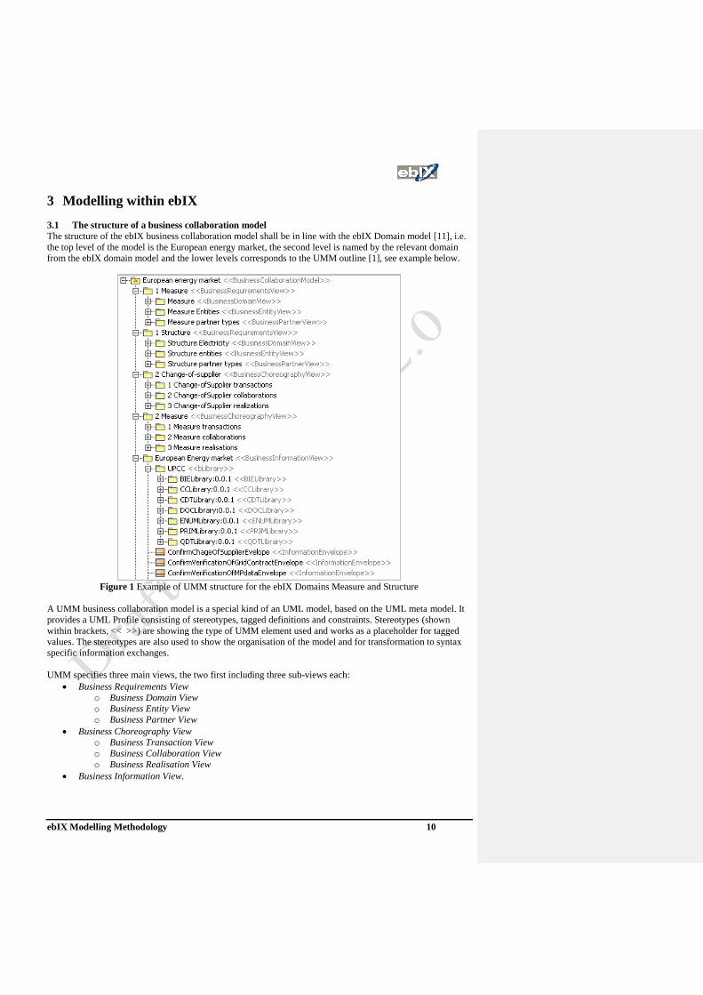
from the ebIX domain model and the lower levels corresponds to the UMM outline [1], see example below.
Figure 1 Example of UMM structure for the ebIX Domains Measure and Structure
A UMM business collaboration model is a special kind of an UML model, based on the UML meta model. It
provides a UML Profile consisting of stereotypes, tagged definitions and constraints. Stereotypes (shown
within brackets, << >>) are showing the type of UMM element used and works as a placeholder for tagged
values. The stereotypes are also used to show the organisation of the model and for transformation to syntax
specific information exchanges.
UMM specifies three main views, the two first including three sub-views each:
• Business Requirements View
o Business Domain View
o Business Entity View
o Business Partner View
• Business Choreography View
o Business Transaction View
o Business Collaboration View
o Business Realisation View
• Business Information View.

ebIX Modelling Methodology 11
The audience for the Business Requirements View is the business users, while the audience for the Business
Choreography View and the Business Information View is technical persons that will implement the modes in
their software systems. These views will be further described later in this chapter.
The Business Requirements View is used for capturing the business collaborations and information entities and
uses common business terms. This view is not meant to be readable by electronic data systems, only by
human readers.
The Business Choreography View and the Business Information View will however be modelled in such a way
that electronic data systems can read and understand the model, e.g. for automatic configuration of
communication systems.
Below is shown an example of the different views used within UMM.
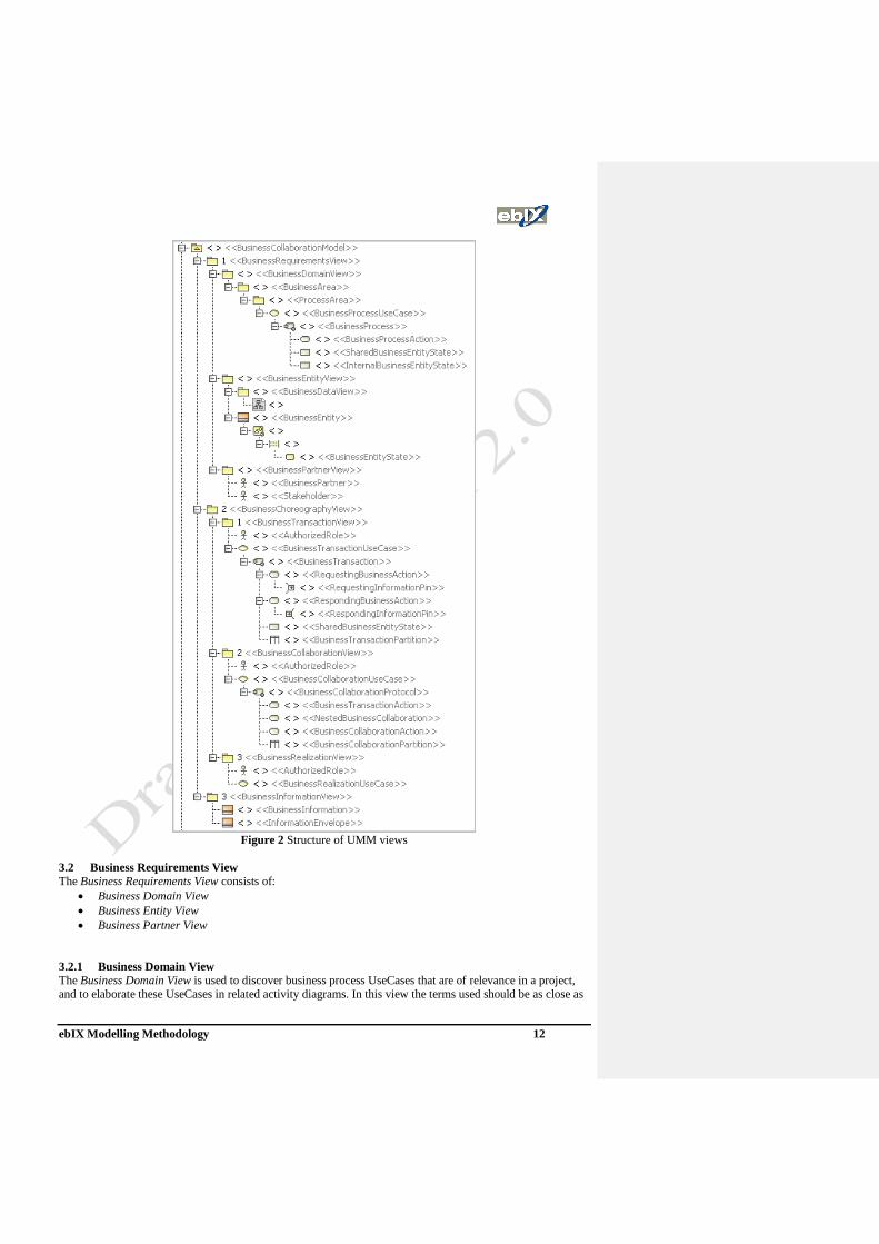
ebIX Modelling Methodology 12
Figure 2 Structure of UMM views
3.2 Business Requirements View
The Business Requirements View consists of:
• Business Domain View
• Business Entity View
• Business Partner View
3.2.1 Business Domain View
The Business Domain View is used to discover business process UseCases that are of relevance in a project,
and to elaborate these UseCases in related activity diagrams. In this view the terms used should be as close as

ebIX Modelling Methodology 13
possible to the terms used within the business area. These terms shall later on, in the Business Choreography
View and the Business Information View, be mapped to standardised terms from the Harmonised role model
[9] and the UN/CEFACT Core Component Library (CCL).
The Business Domain View will be described using a part of, or the whole of, a Business areas or a and
Process areas. Note that a Business area may be orthogonal to a Process area.
Mea
su
re
Business areas
Process
areas
Se
ttle
Stru
ctu
re
Exchange metered data
Change-of-Supplier
Figure 3 Business areas and Process areas
Figure 3 Structure of UMM Business domain view
3.2.2 Business Entity View
In the Business Entity View all relevant entities are elaborated and documented. The entities may be
candidates for business documents, object classes used within the business documents and more abstract
entities used for describing a lifecycle.
ebIX Modelling Methodology 14
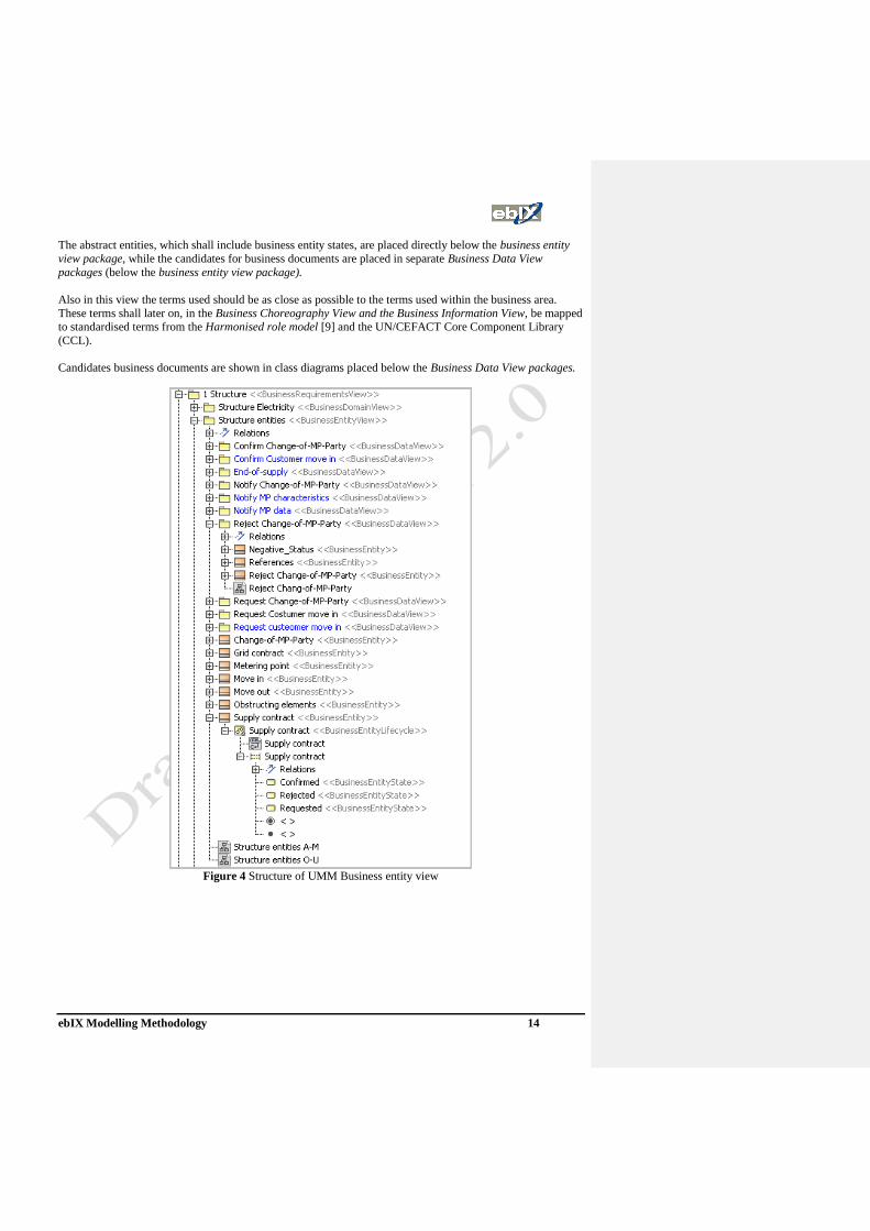
The abstract entities, which shall include business entity states, are placed directly below the business entity
view package, while the candidates for business documents are placed in separate Business Data View
packages (below the business entity view package).
Also in this view the terms used should be as close as possible to the terms used within the business area.
These terms shall later on, in the Business Choreography View and the Business Information View, be mapped
to standardised terms from the Harmonised role model [9] and the UN/CEFACT Core Component Library
(CCL).
Candidates business documents are shown in class diagrams placed below the Business Data View packages.
Figure 4 Structure of UMM Business entity view

ebIX Modelling Methodology 15
3.2.3 Business Partner View
In the Business Partner View all relevant roles are elaborated and documented.
Also in this view the terms used should be as close as possible to the terms used within the business area.
These terms shall later on, in the Business Choreography View and the Business Information View, be mapped
to standardised terms from the Harmonised role model [9]. The ebIX, EFET and ETSO Harmonised role
model itself is placed on the top level of the MagicDraw project, in parallel with the ebIX Business
collaboration model.
Figure 5 Structure of UMM Business partner view
Note that ebIX has added some an additional stereotypes to the Business partner view for roles from the
Harmonised role model, i.e.:
<<HarmonisedRole>> A role taken from the Harmonised European energy market role model from
ebIX, ETSO and EFET [9].
<<BusinessActor>> A role defined within the model itself. This may be a candidate for addition to
the Harmonised role model or a specialisation of a role from the Harmonised
role model.
<<ModelRole>> A generic role (generalisation) of roles, used to simplify the model.
3.3 Business Choreography View
The Business Choreography View consists of:
• Business Transaction View
• Business Collaboration View
• Business Realisation View

ebIX Modelling Methodology 16
3.3.1 Business Transaction View
In the Business Transaction View relevant transactions are modelled. A transaction will always have two
Authorised roles placed within its Business Transaction View package.
A transaction view should be modelled in a generic way, such that the transaction can be reused in the
Business Collaboration View and the Business Realisation View. This also means that the Authorised roles
often will be abstract (generic) roles, later on mapped to real roles in the Business Collaboration View and the
Business Realisation View.
The following generic roles may be used in Business transactions.
Role Transaction pattern (see below)
Responsible role Commercial Transaction, Request/Confirm, Query/Response, Request/Response,
Notification and Information Distribution
Linked role Notification and Information Distribution
Initiating role Commercial Transaction, Request/Confirm, Query/Response and
Request/Response
Affected role Notification and Information Distribution
Note that a Business transaction only concerns two roles at the time.
The transaction documented will always be one of six UMM transaction patterns:
1. Commercial Transaction
2. Request/Confirm
3. Query/Response
4. Request/Response
5. Notification
6. Information Distribution
The business transaction type determines a corresponding business transaction pattern. A business transaction
pattern provides a language and grammar for constructing business transactions. The business transaction type
follows one of the following six property value conventions:
(1) Commercial Transaction used to model the “offer and acceptance” business transaction
process that results in a residual obligation between both parties to
fulfil the terms of the contract.
(2) Query/Response used to query for information that a responding partner already has
e.g. against a fixed data set that resides in a database.
(3) Request/Response used for business contracts when an initiating partner requests
information that a responding partner already has and when the
request for business information requires a complex interdependent
set of results.
(4) Request/Confirm used if an initiating partner asks for information that requires only
confirmation with respect to previously established contracts or with
respect to a responding partner’s business rules.
(5) Information Distribution used to model an informal information exchange business
transaction that therefore has no non-repudiation requirements.
(6) Notification used to model a formal information exchange business transaction
that therefore has non-repudiation requirements
The following figure provides a set of decision criteria for selection of business transaction patterns.

ebIX Modelling Methodology 17
Is this a formal non-
reputable
notification?
Is there a response
required?
Does the responder
already have the
information?
Is context validation
required before
processing by the
receiver?
NoYes
Is there a residual
obligation between
roles to fulfil terms of
the contract?
No
Yes
Select
Commercial
Transaction
Select
Request/
Response
Select
Request/
Confirm
Select
Query/
Response
Yes
No
Yes
No
Select
Information
Distribution
Select
Notification
YesNo
Figure 6 Decision criteria for selection of business transaction patterns (from UMM)
Figure 7 Structure of UMM Business transaction view

ebIX Modelling Methodology 18
3.3.2 Business Collaboration View
A Business Collaboration View is used to define the business choreography of exactly one business
collaboration. This business choreography is specified by the concept of a Business Collaboration Protocol.
The requirements of a Business Collaboration Protocol are captured by a Business Collaboration UseCase.
The Business Collaboration View is composed of exactly one Business Collaboration UseCase and one
Business Collaboration Protocol.
Business collaboration UseCases may optionally have multiple parent Business Collaboration UseCases and
may include multiple Business Transaction UseCases. A Business Collaboration UseCase may also be
extended by additional Business collaboration UseCases
Figure 8 Structure of UMM Business collaboration view
3.3.3 Business Realization View
Business partners identified in the previous Business Requirements View must not directly be associated with
Business Collaboration UseCases and Business Transaction UseCases. In order to specify that a specific set
of Business partners collaborate, we use the concept of a Business realization. Each Business realization is
defined in its own Business Realization View. A Business realization realizes exactly one Business
Collaboration UseCase, but each Business Collaboration UseCase may be realized by multiple business
realizations.
ebIX Modelling Methodology 19
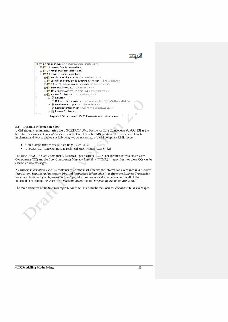
Figure 9 Structure of UMM Business realization view
3.4 Business Information View
UMM strongly recommends using the UN/CEFACT UML Profile for Core Components (UPCC) [3] as the
basis for the Business Information View, which also reflects the ebIX position. UPCC specifies how to
implement and how to deploy the following two standards into a UMM compliant UML model:
• Core Components Message Assembly (CCMA) [4]
• UN/CEFACT Core Component Technical Specification (CCTS ) [2]
The UN/CEFACT’s Core Components Technical Specification (CCTS) [2] specifies how to create Core
Components (CC) and the Core Components Message Assembly (CCMA) [4] specifies how these CCs can be
assembled into messages.
A Business Information View is a container of artefacts that describe the information exchanged in a Business
Transaction. Requesting Information Pins and Responding Information Pins (from the Business Transaction
View) are classified by an Information Envelope, which serves as an abstract container for all of the
information exchanged between the Requesting Action and the Responding Action or vice versa.
The main objective of the Business Information view is to describe the Business documents to be exchanged.
ebIX Modelling Methodology 20
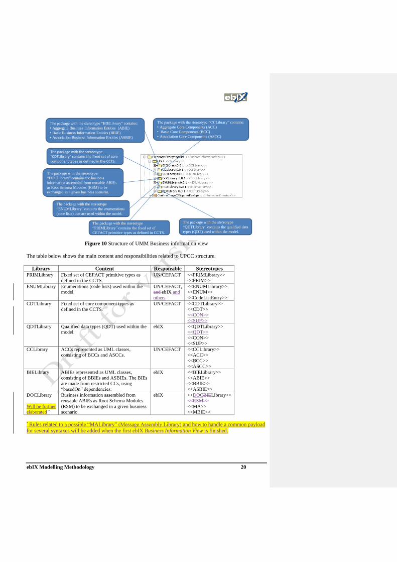
The package with the stereotype
“PRIMLibrary” contains the fixed set of
CEFACT primitive types as defined in CCTS.
The package with the stereotype “CDTLibrary” contains the fixed set of core component types as defined in the CCTS.
The package with the stereotype
“DOCLibrary” contains the business
information assembled from reusable ABIEs
as Root Schema Modules (RSM) to be
exchanged in a given business scenario.
The package with the stereotype
“ENUMLibrary” contains the enumerations
(code lists) that are used within the model.
The package with the stereotype “CCLibrary” contains:
• Aggregate Core Components (ACC)
• Basic Core Components (BCC)
• Association Core Components (ASCC)
The package with the stereotype “BIELibrary” contains:
• Aggregate Business Information Entities (ABIE)
• Basic Business Information Entities (BBIE)
• Association Business Information Entities (ASBIE)
The package with the stereotype
“QDTLibrary” contains the qualified data
types (QDT) used within the model.
Figure 10 Structure of UMM Business information view
The table below shows the main content and responsibilities related to UPCC structure.
Library Content Responsible Stereotypes PRIMLibrary Fixed set of CEFACT primitive types as
defined in the CCTS.
UN/CEFACT <<PRIMLibrary>>
<<PRIM>>
ENUMLibrary
Enumerations (code lists) used within the
model.
UN/CEFACT,
and ebIX and
others
<<ENUMLibrary>>
<<ENUM>>
<<CodeListEntry>>
CDTLibrary Fixed set of core component types as
defined in the CCTS.
UN/CEFACT <<CDTLibrary>>
<<CDT>>
<<CON>>
<<SUP>>
QDTLibrary Qualified data types (QDT) used within the
model.
ebIX <<QDTLibrary>>
<<QDT>>
<<CON>>
<<SUP>>
CCLibrary ACCs represented as UML classes,
consisting of BCCs and ASCCs.
UN/CEFACT <<CCLibrary>>
<<ACC>>
<<BCC>>
<<ASCC>>
BIELibrary ABIEs represented as UML classes,
consisting of BBIEs and ASBIEs. The BIEs
are made from restricted CCs, using
“basedOn” dependencies.
ebIX <<BIELibrary>>
<<ABIE>>
<<BBIE>>
<<ASBIE>>
DOCLibrary
Will be further
elaborated *
Business information assembled from
reusable ABIEs as Root Schema Modules
(RSM) to be exchanged in a given business
scenario.
ebIX <<DOCBIELibrary>>
<<RSM>>
<<MA>>
<<MBIE>>
* Rules related to a possible “MALibrary” (Message Assembly Library) and how to handle a common payload
for several syntaxes will be added when the first ebIX Business Information View is finished.

ebIX Modelling Methodology 21
4 UMM acknowledgement and process behaviour principles This chapter contains an extract from the UMM documentation and will be reviewed after finalisation of a
complete CuS and/or EMD model.
UMM areis using tagged values to specify different needs for how the behaviour of a Business transaction
should be. These tagged values can be found in the different objects within the Business Transaction View.
4.1 Acknowledgements
UMM recognises two types of acknowledgements: Acknowledgement of receipt and Acknowledgement of
processing. The usage of acknowledgements is implicit specified using tagged values, expressing time to
acknowledge, in the Business actions in the Business transaction view. The actual acknowledgement business
information (e.g. messages) is not shown in any of the UMM views. The actual content of the
acknowledgement business information and business rules used within ebIX can be found in the ebIX
Recommendation for acknowledgement and error handling handling [15].
4.1.1 Time to Acknowledge Receipt (Time expression)
The tag TimeToAcknowledgeReceipt related to the stereotype Business Action is used for specifying the time
to acknowledge receipt.
Both partners may agree to mutually verify receipt of business information within a specific time duration.
Acknowledgements of receipt may be sent for both the requesting business information and the responding
business information. This means the sender of the business information may be the requesting authorized role
as well as the responding authorized role – it depends on whether requesting or responding business
information is acknowledged. Similarly, the affirmant may be the requesting authorized role as well as the
responding authorized role – again depending of which business information is acknowledged. Inasmuch we
use the terms sender and affirmant in the explanation of acknowledgement of receipt semantics.
An affirmant must exit the transaction if they are not able to verify the proper receipt of a business
information within agreed timeout period. A sender must retry a business transaction if necessary or must
send notification of failed business control (possibly revoking a contractual offer) if an affirmant does not
verify properly receipt of a business information within the agreed time period. The time to acknowledge
receipt is the maximum duration from the time a business information is sent by a sender until the time a
verification of receipt is “properly received” by the sender (of the business information). Accordingly, the
time to acknowledge receipt is always specified by the sender’s business action, i.e. time counted on the
sender side. This verification of receipt is an auditable business signal and is instrumental in contractual
obligation transfer during a contract formation process (e.g. offer/accept).
4.1.2 Time to Acknowledge Processing (Time expression)
The tag TimeToAcknowledgeProcessing related to the stereotype Business Action is used for specifying the
time to acknowledge processing.
Similarly to the timeToAcknowledgeReceipt, the sender of a business information might be the requesting
authorized role as well as the responding authorized role – depending whether a requesting or a responding
business information is acknowledged. Also the affirmant may be one of the two authorized roles. Thus, we
use again the terms sender and affirmant in the explanation of the acknowledgment of processing semantics.
Both partners may agree to the need for an acknowledgment of processing to be returned by a responding
partner after the requesting business information passes a set of business rules and is handed over to the
application for processing. The time to acknowledge processing of a business information is the duration from
the time a sender sends a business information until the time an acknowledgement of processing is “properly
received” by the sender (of the business information).
ebIX Modelling Methodology 22
Accordingly, the time to acknowledge processing is always specified by the sender’s business action, i.e. time
counted on the sender side. An affirmant must exit the transaction if they are not able to acknowledge
processing of business information within the maximum timeout period. A sender must retry a business
transaction if necessary or must send notification of failed business control (possibly revoking a contractual
offer) if an affirmant does not acknowledge processing of business information within the agreed time period.
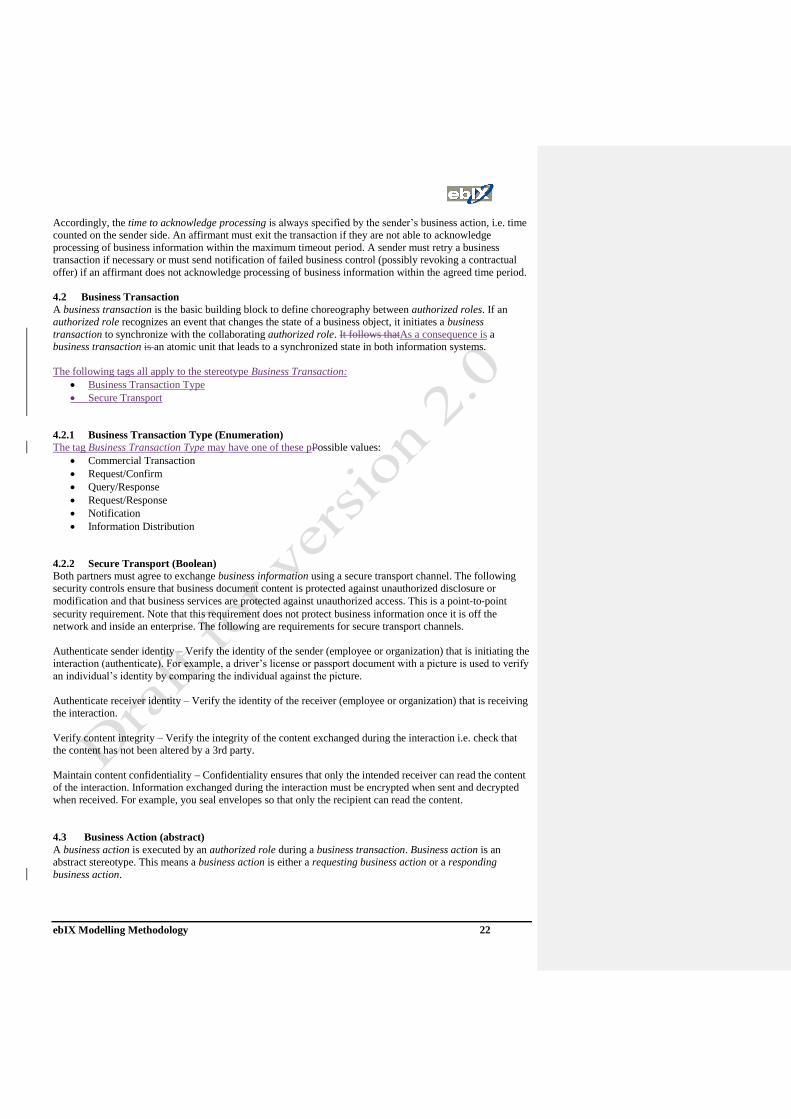
4.2 Business Transaction
A business transaction is the basic building block to define choreography between authorized roles. If an
authorized role recognizes an event that changes the state of a business object, it initiates a business
transaction to synchronize with the collaborating authorized role. It follows thatAs a consequence is a
business transaction is an atomic unit that leads to a synchronized state in both information systems.
The following tags all apply to the stereotype Business Transaction:
• Business Transaction Type
• Secure Transport
4.2.1 Business Transaction Type (Enumeration)
The tag Business Transaction Type may have one of these pPossible values:
• Commercial Transaction
• Request/Confirm
• Query/Response
• Request/Response
• Notification
• Information Distribution
4.2.2 Secure Transport (Boolean)
Both partners must agree to exchange business information using a secure transport channel. The following
security controls ensure that business document content is protected against unauthorized disclosure or
modification and that business services are protected against unauthorized access. This is a point‐to‐point
security requirement. Note that this requirement does not protect business information once it is off the
network and inside an enterprise. The following are requirements for secure transport channels.
Authenticate sender identity – Verify the identity of the sender (employee or organization) that is initiating the
interaction (authenticate). For example, a driver’s license or passport document with a picture is used to verify
an individual’s identity by comparing the individual against the picture.
Authenticate receiver identity – Verify the identity of the receiver (employee or organization) that is receiving
the interaction.
Verify content integrity – Verify the integrity of the content exchanged during the interaction i.e. check that
the content has not been altered by a 3rd party.
Maintain content confidentiality – Confidentiality ensures that only the intended receiver can read the content
of the interaction. Information exchanged during the interaction must be encrypted when sent and decrypted
when received. For example, you seal envelopes so that only the recipient can read the content.
4.3 (Business Action (abstract)
A business action is executed by an authorized role during a business transaction. Business action is an
abstract stereotype. This means a business action is either a requesting business action or a responding
business action.
ebIX Modelling Methodology 23
The following tags all apply to the stereotype Business Transaction:
• isAuthorizationRequired: boolean
• isIntelligibleCheckRequired: boolean
• isNonRepudiationReceiptRequired: boolean
• isNonRepudiationRequired: boolean
• timeToAcknowledgeProcessing: TimeExpression
• timeToAcknowledgeReceipt: TimeExpression
4.3.1 Authorization (Boolean)
If an authorized role needs authorization to request a business action or to respond to a business action then
the sender must sign the business document exchanged and the receiver must validate this business control
and approve the authorizer. A receiver must signal an authorization exception if the sender is not authorized to
perform the business activity. A sender must send notification of failed authorization if a receiver is not
authorized to perform the responding business activity.
4.3.2 Non Repudiation of Receipt (Boolean)
The isNonRepudiationOfReceiptRequired tag requires the receiver of a business information to send a signed
receipt. If the isNonRepudiationOfReceiptRequired tag is false, this indicates that an involved party must not
be able to repudiate the execution of sending the signed receipt.
4.3.3 Non Repudiation (Boolean)
The isNonRepudiationRequired tag is used to indicate that an involved party must not be able to repudiate the
execution of the business action that input/outputs business information.
4.3.34.3.4 Intelligible Check (Boolean)
In order to define the isIntelligibleCheckRequired semantics, we use again the terms sender and affirmant.
Both partners may agree that an affirmant must check that business information is not garbled (unreadable,
unintelligible) before verification of proper receipt is returned to the sender (of the business information).
Verification of receipt must be returned when a document is “accessible” but it is preferable to also check for
garbled transmissions at the same time in a point‐to‐point synchronous business network where partners
interact without going through an asynchronous service provider.
4.4 Process behaviour related to Requesting Business Action (abstract)
A requesting business action is a business action that is performed by an authorized role requesting
business service from another authorized role.
4.4.1 Time to Respond (Time expression)
A business transaction action has to be executed within a specific duration. The initiating partner must send a
failure notification to a responding partner on timeout.
A responding partner simple terminates its activity. The time to perform is the maximum duration between the
moment the requesting authorized role initiates the business transaction action, i.e. sending the requesting
business information envelope, and the moment the requesting authorized role receives a substantive
response. The substantive response is the responding business information envelope if there is any. In case
not, it is the acknowledgement of processing, if any. If not it is the acknowledgement of receipt, if any.

ebIX Modelling Methodology 24
4.4.2 Retry Count (Integer)
The requesting authorized role must re‐initiate the business transaction so many times as specified by the
retry count in case that a time‐out‐exception – by exceeding the time to acknowledge receipt, or the time to
acknowledge processing, or the time to respond – is signaled. This parameter only applies to time‐out signals
and not document content exceptions or sequence validation exceptions – i.e., failed business control
exceptions.
4.5 Process behaviour related to Information Pin (abstract)
The abstract concept information pin represents the incoming/outgoing point for business information in a
business action. Business information is sent from the requesting authorized role to the responding authorized
role or the reverse way. The actual exchanged information is represented using the type business information.
Both concrete stereotypes requesting information pin and responding information pin inherit from the abstract
stereotype information pin.
4.5.1 Confidential (Boolean)
If the flag is set, the exchanged information is encrypted so that unauthorized parties cannot view the
information.
4.5.2 Tamper Proof (Boolean)
If the flag is set, the exchanged information has an encrypted message digest that can be used to check if the
message has been tampered with. This requires a digital signature (sender’s digital certificate and encrypted
message digest) associated with the document entity.
4.5.3 Authenticated (Boolean)
If the flag is set, there is a digital certificate associated with the document entity. This provides proof of the
signer’s identity.

ebIX Modelling Methodology 25
5 Versioning
5.1 Versioning of XML schemas
ebIX will follow the rules given by in the UN/CEFACT XML Naming and Design Rules (NDR) related to
versioning scheme, consisting of:
• Status of the XML Schema file,
• A major version number,
• A minor version number and
• A revision number.
These values are declared in the version attribute in the xsd:schema element. The major version number is
also reflected in the namespace declaration for each XML Schema file.
The xsd:schema version attribute MUST use the following template:
<xsd:schema ... version=”<major>”p”<minor>[”p”<revision>]”>
Where:
<major> = sequential number of the major version.
<minor> = sequential number of the minor version.
<revision> = optional sequential number of the Revision.
5.1.1 Major Versions
A major version of a UN/CEFACT XML Schema file constitutes significant non- backwards compatible
changes. If any XML instance based on an older major version of UN/CEFACT XML Schema attempts
validation against a newer version, it may experience validation errors. A new major version will be produced
when non- backward compatible changes occur. This would include the following changes:
• Removing or changing values in enumerations
• Changing of element names, type names and attribute names
• Changing the structures so as to break polymorphic processing capabilities
• Deleting or adding mandatory elements or attributes
• Changing cardinality from mandatory to optional
Major version numbers will be based on logical progressions to ensure semantic understanding of the
approach and guarantee consistency in representation. Non- negative, sequentially assigned incremental
integers satisfy this requirement.
Every XML Schema File major version number MUST be a sequentially assigned incremental integer greater
than zero.
5.1.2 Minor Versions
The minor versioning of an XML Schema file identifies its compatibility with the preceding and subsequently
minor versions within the same major version.
Within a major version of an UN/CEFACT XML Schema file there can be a series of minor, or backward
compatible, changes. The minor versioning of an UN/CEFACT XML Schema file determines its compatibility
with UN/CEFACT XML Schema files with preceding and subsequent minor versions within the same major
version. The minor versioning scheme thus helps to identify backward and forward compatibility. Minor
versions will only be increased when compatible changes occur, i.e

ebIX Modelling Methodology 26
• Adding values to enumerations
• Optional extensions
• Add optional elements
Minor versioning MUST be limited to declaring new optional XML content, extending existing XML content,
or refinements of an optional nature.
Minor versions will be declared using the xsd:version attribute in the xsd:schema element. It is only necessary
to declare the minor version in the schema version attribute since instance documents with different minor
versions are compatible with the major version held in the same namespace. By using the version attribute in
each document instance, the application can provide the appropriate logic switch for different compatible
versions without having knowledge of the schema version which the document instance was delivered.
Minor version changes are not allowed to break compatibility with previous versions within the same major
version. Compatibility includes consistency in naming of the schema constructs to include elements,
attributes, and types. UN/CEFACT minor version changes will not include renaming XML Schema
constructs.
For a particular namespace, the major version and subsequent 975 minor versions and revisions create a linear
relationship.
Rules related to the minor version number:
• Minor versions MUST NOT rename existing XML Schema defined artifacts.
• Changes in minor versions MUST NOT break semantic compatibility with prior versions having the
same major version number. • XML Schema Files for a minor version XML Schema MUST incorporate all XML Schema
components from the immediately preceding version of the XML Schema File.
5.2 Versioning of UMM models
To be done.

ebIX Modelling Methodology 27
56 Submissions to UN/CEFACT The submission of ebIX business collaboration models to UN/CEFACT shall be in line with the requirements
from:
• UN/CEFACT Business Requirements Specification (BRS) Documentation Template [5]
• UN/CEFACT Requirements Specification Mapping (RSM) Documentation Template and Conformity
Rules [6]

ebIX Modelling Methodology 28
67 ebIX transformation rules
This chapter will be rewritten!
6.17.1 Business document type
A business document has a business document type that is defined by:
• the nature of the business transaction where it is being used,
• the role responsible for the information in the business transaction and
• the direction of the information flow.
A business document has a certain structure that is determined by:
• the Business document type,
• the Business sector (e.g. electricity or gas),
• the Ancillary-role (the role explicitly included in the header part of the business document),
• the “Reason for transaction” (i.e. in which business process the business transaction is used) and
• the Business document function code (e.g. add, change or delete).
The following rules apply for the business document type:
• There can only be one responsible role for the information components in a business document type.
• The actual information content of a business document may be a subset of the total information
components structure of a certain business document type, dependent on the business sector, the “non-
responsible” role, the attribute “Reason for transaction” and the Business document function code.
• The “responsible” role in the business transaction is implicit given by the business document type.
• The “non-responsible” role is explicitly specified in the header section of the business document.
• A business document may contain several instances of transactions, of the same type.
Transaction
pattern
Responsible role included in the
document type
Ancillary-role (explicit given in the
business document header)
Commercial
Transaction
Request/Confirm
Query/Response The “Responsible role” is the role
receiving the initiating document.
Sender role in the initiating document
Receiver role in the responding document
Request/Response See above Sender role in the initiating document
Receiver role in the responding document
Notification The “Responsible role” is the role
sending the document.
Receiver role
Information
Distribution
Notice that it may be different Reasons for transactions and/or Business document function codes within a
business document, dependent on the requirements given in the class diagram for the business document. The
responsible role (sender or receiver) is implicit given by the business document type.
Each business document is specified using a UML class diagram. The class diagram shall describe the
classification of the attributes as required (no cardinality – default cardinality) or dependent (0..1). A general
rule within ebIX is to see all optional elements as dependent and describe the dependency in a dependency
matrix associated with the business document. If an element is dependent on national rules the attribute must
be specified in national user guides. This shall be stated in the ebIX business collaboration model.

ebIX Modelling Methodology 29
6.27.2 Dependency matrix
The ETC meeting 10081002 proposes to remove this chapter.
Given the principles specified above, it might be possible to use dependency matrices for specifying how to
reuse business documents within a given syntax. A specific business document, identified by a business
document type, might be used in different business processes, dependent on the syntax. A dependency matrix
is set up to show the dependency for different usage. The attribute Reason for transaction will specify in
which business process the business document is used. Different usage of attributes or classes will often be
related to the relevant Reason for transaction.
Dependency matrices are typically used for simplifying the implementation of syntax specific messages and
may be used for specifying the usage of attributes dependent on other attributes in the messages or to specify
allowed codes.
6.37.3 Business Document Set
In the present ebIX models we find Business Documents being specified in the Class Diagrams. For efficiency
reasons we may still want to be able to combine Business Documents in a set for the exchange with another
party, for certain syntaxes. So in the models, the information to be exchanged could be regarded as bottom-up
defined, since the business defines the information, which is only later combined in a set.
Several Business Documents may be combined in one Business Document Set:
BusinessDocumentSet
+identifier : BusinessDocumentSet_ID...
xxx_BusinessDocument
Data
Type
1
1
1..*
Figure 11 Business Document Set (overview)
There are conditions that have to be met in order to combine Business Documents in one set. Business
Documents may only be combined in one Business Document Set if they have the same information the two
upper Classes in the Class Diagram (the Class “xxx_BusinessDocument” and the Class
“BusinessDocumentType”). Additionally there may be special conditions related to the chosen syntax.

ebIX Modelling Methodology 30
392_BusinessDocument
+requestForAcknowledgementOf Acceptance : ebIX 01C::QDT::ResponseType_Code = AB{SG=0}
+messageDateTime : ebIX 01C::QDT::DateTime{SG=0, Qualifier=DTM-C507.2005=137}
+@marketDomain : ebIX 01C::QDT::MarketDomain_Code = E01{frozen, SG=0}
+receiverID : ebIX 01C::QDT::Party_ID{SG=2, Qualifier=NAD-3035=MR}
+senderID : ebIX 01C::QDT::Party_ID{SG=2, Qualifier=NAD-3035=MS}
+timeZone : ebIX 01C::QDT::TimeZone{SG=0}
BusinessDocumentType
+@reasonForTransaction : ebIX 01C::QDT::ReasonForTransaction_Code = E56{frozen, SG=4}
+@function : ebIX 01C::QDT::BusinessDocumentFunction_Code = 9{frozen, SG=0}
+@businessSector : ebIX 01C::QDT::BusinessSector_Code = 23{frozen, SG=0}
+@type : ebIX 01C::QDT::BusinessDocumentType_Code = 392{frozen, SG=0}
+@ancillaryRole : ebIX 01C::QDT::Role_Code = DDQ{frozen, SG=2}
+@classDiagramVersion : UDT::Identifier [0]{frozen}
Contract
+startDate : ebIX 01C::QDT::DateTime{SG=4, Qualifier=DTM-C507.2005=92}...
MeteringPoint
+meterReadingInstruction : ebIX 01C::QDT::Instruction_Code [0..1]{SG=4}
+identifier : ebIX 01C::QDT::Domain_ID{SG=4, Qualifier=LOC-3227=172}
Author ksparreb
Creation date 2/7/05 6:19 PM
Modification date 2/9/05 5:22 PM
Structure Edifact , UTILMD , 01C
Diagram name 392, 23, E56, DDQ, 9
Documentation
CD Description Request change Balance Responsible
BusinessDocumentData
+identifier : ebIX 01C::QDT::BusinessDocument_ID{SG=4}...
MP_Address
+buildingNumber : char{Data=NAD-C059.3042, SG=11}
+postCode : ebIX 01C::QDT::Postal_Code{SG=11}
Party
+identifier : ebIX 01C::QDT::Party_ID{SG=11}
<<enumeration>>
Instruction_Code
(CodeList ebIX)
E01 (No meter reading available)
version: not yet used
New balance Responsible
{Qualifier=NAD-3035=DDK,
SG=11}
1
1
{Qualifier=NAD-3035=IT,
SG=11}
0..1
1
1
1
Figure 12 Business Document Set (details)
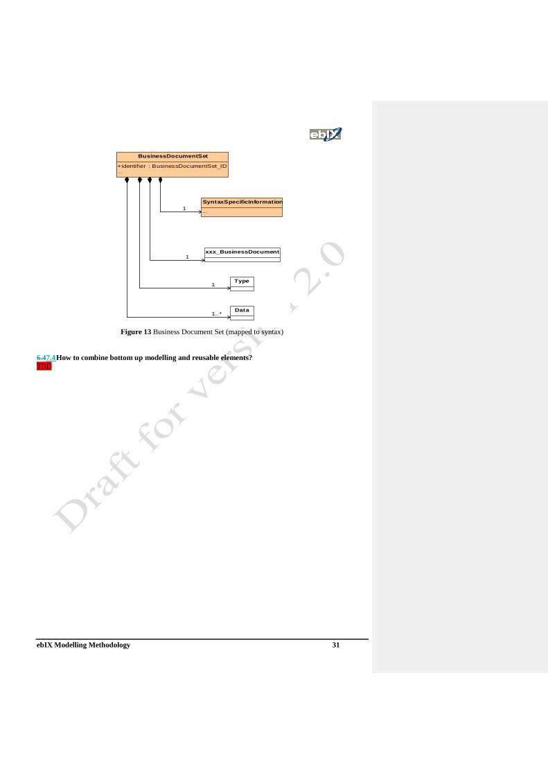
This condition is represented in the model below. As you see:
• a set may only contain one instance of the class Exx_BusinessDocument
• a set may only contain one instance of the class BusinessDocumentType
• the only information the BusinessDocumentSet adds to the combination of BusinessDocuments is the ID
for the BusinessDocumentSet.
This enables us to combine several sets of “data” in one BusinessDocumentSet, as long as they have the two
classes that describe the information in common.
ebIX Modelling Methodology 31
BusinessDocumentSet
+identifier : BusinessDocumentSet_ID...
SyntaxSpecificInformation
...
xxx_BusinessDocument
Data
Type
1..*
1
1
1
Figure 13 Business Document Set (mapped to syntax)
6.47.4 How to combine bottom up modelling and reusable elements?
TBD

ebIX Modelling Methodology 32
6.57.5 Relations between versioned modelling elements
To be updated.
ebIX model versions are determined by the versions of the components used in the model. The figure below
shows the relations between the various elements used in the modelling.
model ebIX
SyntaxMappedClass
UseCase
+version [1]
Sequence
+version [1]
Class
+version [1]
Activity
+version [1]
SyntaxMappedCC
+version [1]
CC ebIX
ebIX
+version [1]
BBIE
+version [1]
ABIE
+version [1]
QDT
+version [1]
role model
role
+version [1]
domain
+version [1]
installation
+version [1]
CC UN/CEFACT
UDT
+version [1]
ACC
+version [1]
BCC
+version [1]
UN/Cefact
+version [1]
+version [1]
ebIX acknowledgement and error report
ebIX recommendations for cancellation
+version [1]
ebIX rules and recommendations
+version [1]
documents ebIX
ebIX methodology
+version [1]
UN/Cefact naming and design rules
+version [1]
documents UN/CEFACT
XML
+version [1]
Edifact
+version [1]
codelists UN/CEFACT
codelist
+version [1]
codelists ebIX
codelist
+version [1]
+version [1]
Core Components
national domain
+version [1]
national model
+version [1]
ebIX domain
+version [1]
Role model
+version [1]
ebIX model
+version [1]
Syntax
+version [1]
ebIX EFET ETSO UCTE IEC
0..*
0..10..1
1..* 1..*
Figure 14 Relations between versioned modelling elements

ebIX Modelling Methodology 33
78 Syntax specific documentsTechnology specific requirements
7.18.1 Introduction
We have channel requirements and syntax requirements. The channel requirements relate to the type of
communication used, while the syntax requirements relate to which syntax to use, e.g. XML or EDIFACT.
Channel requirements do have a strong impact on Acknowledgements and process behaviour. Chapter 4 is
outlining how process behaviour and acknowledgement can be determined by stereotypes and tagged values
to keep this channel related information apart from the process models itself.
7.28.2 Channel requirements
As a principle, information from the channel itself shall not be interpreted in a way that is not defined within
the channel. For instance file names shall never be used to transport relevant information. However the
channel can supply relevant information if defined explicitly within the channel. For instance:
• A channel that is limited to only one business document type, e.g. WS (WEB-service).
• The sender id for channels that require authentication of the sender.
The ebIX Methodology is not mandating any special standard for message envelopes, such as SOAP or
ebXML-MS or the European Communication Platform (ECP) from ETSO. However channels can demand the
use of a specific header structure, such as SOAP, ebXML-MS or ECP.
7.2.1 Asynchronous or synchronous channels requirements
7.2.2 Christoph and Kees: make some sentences
Different communication channels require different information in the header part of a business document.
For example in the case of a WS the receiver part will be known through the address of the WS and if
authentication of the sender is required also the sender id will be given directly from the WS. This means that
the requirements for header information will vary by the type of communication cannel and syntax. For this
reason the header part of a business document will never be modelled in the UMM Business requirements
View. Business document header specifically made for each communication cannel and syntax will be added
in the Business Information View. The content of a header may include sender and receiver id, document type,
relevant dates and references.
Similar to different requirements for header information, also the requirements for bundling of the detail
section of the business documents may vary between different communication channels and syntaxes. For this
reason the cardinality between the document header and the detailed sections may be specified as 1 or 1..* in
the Business Information View, depending on the syntax and communication channel.
In case of asynchronous communication channel (e.g. SMTP) every business document exchanged shall be
acknowledged, either by an acknowledgement of receipt, an acknowledgement of processing or a responding
business document. This rule does not apply for the acknowledgements themselves. Maintaining this rule is
ensuring that both communication partners have a synchronous knowledge of the transaction.
• Adding header
• Adding references
• Bundling or sets
• Belgian revolution rules
• Dealing with acknowledgements
• Filling envelope, e.g. SOAP.
7.2.38.2.1 Choreography
Where to put WS specifications (tagged values in the Business transaction actions?).
Kees: make some sentencesTo be done.
ebIX Modelling Methodology 34
7.38.3 Syntax mapping
7.3.18.3.1 XML
XML schemas shall be based on the UN/CEFACT XML Naming and Design Rules (NDR) [14].
7.3.28.3.2 EDIFACT
7.3.2.18.3.2.1 Basic rules
The current solution for mapping between a UML Class diagram and EDIFACT requires the following steps:
1) Find a suitable EDIFACT message:
a) Compare the functional definition of the process and business document with the definitions of
EDIFACT messages, preferably EDIFACT messages made for the energy industry, such as UTILMD
or UTILTS. If a definition matches or matches satisfactorily, take the EDIFACT message as a basis
and request extension of the EDIFACT functional definition with the missing functions. Otherwise,
request a new EDIFACT message.
b) For each class and attribute within this class, find segment groups and segments of which the
definition matches, possibly at a more generic level of abstraction. If no segment matches, request a
new (generic) segment.
c) Ensure that the segments used within the EDIFACT structure are in the same level as in the Class
diagram. If the level within the EDIFACT message not matches the levels in the class diagram, and
workarounds are not possible, request an EDIFACT message structure change.
d) If the segment found is qualified, look in the segment’s qualifier code list for a qualifier that matches
the specific definition of the attribute. If none is found, request a new one. If the definition of an
existing qualifier may be slightly adapted, request a change.
e) Check the structure of the segment. In many cases the structure will not match the structure of the
class/attribute. If the element and sub-element structure of the segment match the attribute, and if the
definitions also match, use the elements. Request changes and additions to the segment structure
where appropriate.
2) Document the relationship between the Class diagram (ABIE/BBIE) and the EDIFACT message:
a) Add the appropriate EDIFACT elements; Segment group, Segment, Composite element, Data
element, and Qualifier, to the Class diagram.
7.3.2.28.3.2.2 EDIFACT structure as UML tagged values
ebIX has created a set of tagged values and rules to facilitate the creation of syntax dependent interchange
formats for EDIFACT. The use of tags is differentiated over the mapping levels, i.e.:
➢ Class diagram
➢ Relation
➢ Class
➢ Attribute
➢ Qualified data type (QDT)
The following rules apply:
• In a Class Diagram the common structural mapping values for a set of elements shall be linked to the
next higher level;
• Mapping values for data shall preferably be linked to the Qualified data types (and so become
reusable).
The following tagged values have been defined by ebIX:

ebIX Modelling Methodology 35
Tag Comments
Structure • The tag “Structure” is used for mapping on class diagram level
Structure =<syntax>, <UNSM>, <version>
<syntax> = EDIFACT
<UNSM> = UTILMD or UTILTS
<version> 01C, 02B or 07B
Diagram
name • The tag “Diagram name” is used for mapping on class diagram level
Structure =<syntax>, <UNSM>, <version>
<syntax> = EDIFACT
<UNSM> = UTILMD or UTILTS
<version> 01C, 02B or 07B
SG • The tag “SG” (Segment Group) is used for mapping on relation- and data-
level
• The values for SG include all numbers of segment groups as required.
SG=<group number>
Qualifier • Tagged values for “Qualifier” are only used for information that is syntax
dependent and for which in EDIFACT qualifiers have to be used.
Qualifier=<Segment-Composite data element.data element=<value>>)
Data • For attributes for which the data type is not qualified the data itself have to be
mapped on attribute level using the tag “Data” and optionally qualifying
information.
• The mapping on Qualified Data Type level regards the data itself and uses
the tag “Data” and optionally qualifying information (see above)
Data= <Segment-Composite data element.data element=<value>>
Comments to the table:
• Text in Italic is optional.
• The delimiter used between Segment and Composite Data Element is hyphen ‘-‘.
• The delimiter used between Composite Data Element and the Data Element or between Data Elements
within one Composite Data Element is full stop ‘.‘.
• Each data element has a separate value for the tags “Qualifier” and “Data”.
• The tagged values for a Class Diagram as such (“Structure”) are represented in the “Diagram
Information” in the Class Diagram.
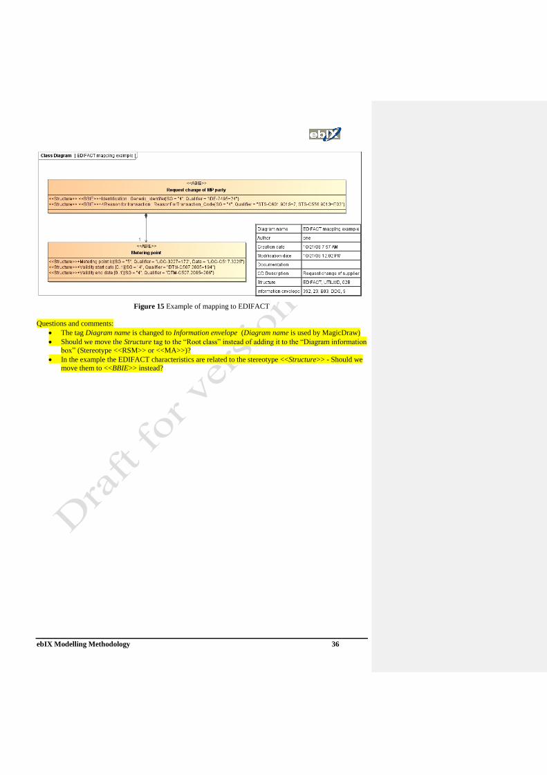
ebIX Modelling Methodology 36
Figure 15 Example of mapping to EDIFACT
Questions and comments:
• The tag Diagram name is changed to Information envelope (Diagram name is used by MagicDraw)
• Should we move the Structure tag to the “Root class” instead of adding it to the “Diagram information
box” (Stereotype <<RSM>> or <<MA>>)?
• In the example the EDIFACT characteristics are related to the stereotype <<Structure>> - Should we
move them to <<BBIE>> instead?
ebIX Modelling Methodology 37
89 Table of figures
Figure 1 Example of UMM structure for the ebIX Domains Measure and Structure ...................................... 10 Figure 2 Structure of UMM views.................................................................................................................... 12 Figure 3 Business areas and Process areas ....................................................................................................... 13 Figure 4 Structure of UMM Business domain view ......................................................................................... 13 Figure 5 Structure of UMM Business entity view ............................................................................................ 14 Figure 6 Structure of UMM Business partner view .......................................................................................... 15 Figure 7 Generic roles used in the Business Transaction View ........................ Error! Bookmark not defined. Figure 8 Decision criteria for selection of business transaction patterns (from UMM) ................................... 17 Figure 9 Structure of UMM Business transaction view ................................................................................... 17 Figure 10 Structure of UMM Business collaboration view .............................................................................. 18 Figure 11 Structure of UMM Business realization view .................................................................................. 19 Figure 12 Structure of UMM Business information view ................................................................................ 20 Figure 13 Business Document Set (overview) ................................................................................................. 29 Figure 14 Business Document Set (details) ...................................................................................................... 30 Figure 15 Business Document Set (mapped to syntax) .................................................................................... 31 Figure 16 Relations between versioned modelling elements ............................................................................ 32 Figure 17 Example of mapping to EDIFACT .................................................................................................. 36 Figure 18 ebIX methodology outline ................................................................................................................ 39 Figure 19 Business Partners (example) ............................................................................................................ 49 Figure 20 Business Entity State Diagram (example) ........................................................................................ 50 Figure 21 Business Process UseCase (example) .............................................................................................. 51 Figure 22 Business Process UseCase with sub-processes (example) ............................................................... 51 Figure 23 Business Process Activity (example) ................................................................................................ 52 Figure 24 Business Transaction UseCase (example) ....................................................................................... 53 Figure 25 Business Transaction Activity (example) ......................................................................................... 53 Figure 26 Business Collaboration UseCase (example) .................................................................................... 55 Figure 27 Business Collaboration Protocol (example) .................................................................................... 56 Figure 28 Nested Business Collaboration Protocol (example) ........................................................................ 56 Figure 29 Business Realization (example) ........................................................................................................ 59 Figure 30 UseCase diagram .............................................................................................................................. 63 Figure 31 association ........................................................................................................................................ 65 Figure 32 Generalisation .................................................................................................................................. 65 Figure 33 UseCase diagram with include and extend relations ........................................................................ 66 Figure 34 Activity with actions ........................................................................................................................ 68 Figure 35 Actions with input pins and output pins ........................................................................................... 69 Figure 36 Call Behaviour Action ...................................................................................................................... 70 Figure 37 Class ................................................................................................................................................. 71 Figure 38 Enumeration ..................................................................................................................................... 72 Figure 39 Associations ..................................................................................................................................... 73 Figure 40 Compositions and Aggregations ...................................................................................................... 73 Figure 41 Association class .............................................................................................................................. 74 Figure 42 Multiplicity ....................................................................................................................................... 74 Figure 43 Dependency ...................................................................................................................................... 75 Figure 44 Generalisation .................................................................................................................................. 75 Figure 45 Realisation ........................................................................................................................................ 76 Figure 46 Example of class diagram ................................................................................................................ 77 Figure 47 Protocol state machine ..................................................................................................................... 79 Figure 48 Object nodes with states ................................................................................................................... 79

ebIX Modelling Methodology 38
Appendix A ebIX projects
The ebIX modelling methodology is a further development (extension) of the methodology agreed between
ebIX, ETSO and EFET and requires among others the use of UMM to describe the business processes in
question. It is aimed at the creation of ebIX business collaboration models for defined business process areas,
or parts of a business process area, within the energy market. It is a 9-step process with 5 key milestones that
concludes with a business collaboration model and a set of translation guides, approved and posted to the
ebIX web site for implementation.
This chapter should be reviewed by everyone:
• It is a mixture of project and modelling rules
• It’s based on at harmonised model between ETSO and ebIX, but changed by ebIX
• Is it here from historical reasons?
• Deliverables from ebIX projects (user documentation)
o How to structure?
o Made for whom?
o BRS/RSM?
o Let the work groups decide?

ebIX Modelling Methodology 39
A.1 The ebIX Modelling project outline
Figure 16 ebIX methodology outline
Each of the 8 steps can be resumed as follows:
1. Prior to any project development a Business area, or a Process area (part of a business area), for
development has to be identified and approved. Any ebIX participating member may submit a
development area for consideration. The submission method or content has not been formalised. It is the

ebIX Modelling Methodology 40
knowledge within the evaluation team of business practises covering several countries that will determine
the validity or not of setting up a project.
2. Once the development area is approved a project team is set up to prepare a detailed project plan. This
plan once approved will form the basis of all future development work. It provides a perspective of the
area that is to be covered and the expected deliverables. Once the project plan has been approved the first
milestone of development has been reached. This is project management and should probably not be a
part of the ebIX methodology.
3. Project development then begins and UseCase diagrams are produced which detail the project
requirements.
4. The UseCase diagrams from step 3 must be compared with the relevant part of the ebIX Domain model,
[11], to see if the UseCase diagrams are aligned. In the case where the ebIX Domain model, [11], does not
cover all the processes defined within the project a modification request is initialised in order to adjust the
ebIX Domain model, [11].
5. In the case where the role model does not cover all the roles or domains necessary to satisfy the project
requirements a modification request is initialised in order to adjust the Role model once the business
process development has confirmed their use.
Once the project requirements have been scoped within the Domain model and the Role model the second
milestone of development has been reached.
6. The business processes are then developed within the frame of the UMM Business Requirement View
using UseCase diagrams, activity diagrams, and/or state diagrams. Through these diagrams the workflow
of the business processes in question is developed. This process refines the project’s scope. If additional
roles or domains are identified, a maintenance request is submitted to the Domain model [11]or the
Harmonised role model, [9], maintenance group. The Role model and Domain model adjustments may be
an iterative process and will continue until the project’s scope has been successfully integrated into it.
This process may additionally require modifications to the project requirements. The main deliverable
from this activity is a Business Requirement Specification (BRS), which shall be in line with the
UN/CEFACT BRS Documentation Template. The approval of the business processes signifies that the
third milestone of development has been reached.
7. From the business processes and workflow diagrams, the required set of information requirements can be
identified. Each business document identified between two roles that are determined as being a candidate
for automation is modelled within the UMM Business Choreography View and the Business Information
View. The business processes will be shown as UseCase diagrams and Activity diagrams, while the actual
information exchanged will be presented using class diagrams. The ebIX core components are
interrogated to make use of existing objects or core components. New core components are added to the
repository if necessary. The approval of the collaboration model signifies that the fourth milestone of the
development has been reached. 8. From the class diagrams syntax specific documents, such as XML schemas and EDIFACT guides are
made. The main deliverable from this activity is a Requirement Specification Mapping (RSM), which
shall be in line with the UN/CEFACT RSM Documentation Template and the layout key for ebIX
documents. The approval of the syntax specific deleverables signifies that the fifth and final milestone of
development has been reached. The approved business collaboration model is then inserted in the ebIX
web site for implementation.
The requirements necessary to satisfy each of the milestones will be covered in more detail in the next
chapters of this document. In relation to the UMM one can easily see that the inception phase which addresses
the workflows of business modelling and requirements are covered by the first six milestones, and the
elaboration phase which addresses the workflows of analysis and design are covered with the seventh
milestone. The eight milestone is not addressed within the UMM.
A.2 Milestone requirements
A.2.1 Milestone 1. Project approved for development This is project management and should probably not be a part of the ebIX methodology.

ebIX Modelling Methodology 41
The initial phase of starting up an ebIX process is to prepare a project plan. A project plan can only be
developed against an approved development area.
The project plan will contain the following:
1. Presentation of the project,
2. Outline of the goals and benefits
3. Explanation of how it is going to be organised,
4. Description of the deliverables,
5. Establishment of the initial timetable,
6. Declaration of needed resources,
7. Presentation of the development costs.
The presentation of the project will describe a single and complete business area, or process area. It will
provide the framework for the future development.
The goals must be clearly stated and measurable.
The organisation of the project will identify a project leader and the team that is going to work on the project.
The members of the team must have a commitment from their organisation that they, or their replacement,
will follow the project through to completion.
The deliverables, which are generally one business collaboration model and a set of translation guides, will
define what is to be expected when the project has been terminated.
The initial timetable will be built identifying the key development milestones. For example, the four
milestones of development could be used as the principal milestones for the development of the deliverables.
The milestones are not necessarily limited to those outlined in this methodology. However, the basic
milestones must be outlined as a minimum.
If external consulting resources are to be used these should be identified here along with any travel costs that
may be required. ebIX members finance the project through their time, where their expected contribution is
over and above the normal time necessary for meeting preparation and meeting time then this should be
identified.
The key deliverable of this milestone is the project plan, which has to receive official ebIX approval before
the project itself can be launched. It is recommended that the approval process in question be identified in the
project plan.
A.2.2 Milestone 2: Scope defined The initial task of the project is to situate it within its general context and in more detail. Once the context has
been defined through the development of UseCases, all the roles necessary to complete the task and the
models placement within the ebIX Domain model will have been identified.
ebIX has together with ETSO/TF-EDI and EFET developed the Harmonised role model, [9], that is used to
identify areas of interest and all the roles and domains necessary to satisfy them. This role model is a living
model that outlines all the roles and domains with their principal interactions within the industry. It is
consequently not necessary in the preparatory stages to spend a significant amount of time working on the
overall business domain. This task is already catered for within the role model.
However, during the development of the project requirements it may happen that roles that have not
previously been identified may appear. The project should prepare a maintenance request to change the role
model. This request will be confirmed during the next development phase.

ebIX Modelling Methodology 42
The key deliverables at this milestone is as follows:
• An outline of the project scope identifying all the roles and domains in the role model that will come
into play in the project;
• A reference to where the model fits within the ebIX Domain model.
• The initial version UseCases describing the requirements and their explanatory text.
• An eventual revised version of the role model along with the maintenance requests outlining the
revisions;
A.2.3 Milestone 3: Business process defined The business process analysis stage builds on the UseCases that have been developed during the project
requirements stage. It introduces activity diagrams, state diagrams and optionally sequence diagrams that
show the interactions between the various roles. These are placed in the context of the UseCases previously
defined.
The UseCases may be refined at this milestone, as more information becomes available. This provides
clarification to more detailed points that are not necessary during a requirements development process. For
example more detailed UseCases may be developed to show up particular contexts that are necessary in order
to describe completely the business process in question.
However, if a UseCase described during the requirements step is completely put into question then it may be
necessary to reiterate the requirements phase completely.
This stage of the methodology will also identify the workflow requirements for the business process. It will
identify all the information flows (business documents) between the different roles that are necessary to
satisfy the requirements. The relationships between the information flows will also be developed.
The need for any new roles or domains is confirmed and appropriate maintenance requests are submitted to
the role model maintenance group. The role model maintenance process may immediately approve the new
role or they may require clarification or suggest the use of another role. This is an iterative process that shall
continue until the project has a satisfactory solution to the roles that it wishes to present in its project
requirement and business collaboration models.
The key deliverables at this milestone are as follows:
• A Business Requirement Specification (BRS), made in accordance to the UN/CEFACT BRS
Documentation Template, i.e.:
o The finalised version of the business process UseCases and the associated explanatory test.
o The activity diagrams and optional state diagrams and sequence diagrams, and associated text
describing the interactions between the roles. This includes workflow requirements for the
business process and business documents between roles necessary to satisfy the business
requirements.
• If any, the finalised role model maintenance requests.
During this activity the first versions of the needed information should be made as simple class diagrams.
Knowing the rough content of the business documents makes it easier for the project group to discuss the
sequence and activity diagrams. Note that these class diagrams only are meant for helping the project group in
defining the business processes. Final class diagrams, to be used for generating syntax specific information
exchanges, will be developed in the next steps.
A.2.4 Milestone 4: Information requirements defined The workflow of the business processes from the UMM Business Requirements View is elaborated in
accordance to the requirements from the UMM Business Choreography View. The deliverables from the UMM

ebIX Modelling Methodology 43
Business Choreography View is a business process model, which may be read and executed by electronic
means (i.e. a software system).
All the business documents that have been identified will be further analysed to identify their content and
documented according to requirements from the UMM Business Information View and the UN/CEFACT
Profile for Core Components (UPCC). Class diagrams will be used for this purpose.
During this analysis the ebIX core components will be examined in order to determine whether or not existing
objects or components will satisfy the requirements. If so, they will be introduced into the model. If a core
component could satisfy the requirement with the adjustment of the definition then a maintenance request
should be placed against the ebIX core components repository. Ask ETC (ebIX Technical Committee) for a
new core component if an equivalent core component cannot be found. For certain core components there are
associated code lists. Ask ETC for a code if a new code is required.
The key deliverable from this activity is a Requirement Specification Mapping (RSM), which shall be in line
with the UN/CEFACT RSM Documentation Template and the layout key for ebIX documents.
A.2.5 Milestone 5: Business collaboration model and translation guides approved ebIX project chooses which technologies to be used, e.g. XML, Web services or EDIFACT. The deliverables
from this milestone will depend on the syntax chosen.

ebIX Modelling Methodology 44
Appendix B ebIX MagicDraw CC/UMM profile When working with the ebIX MagicDraw CC/UMM profile, one of the following projects should be opened:
• Measure.mdzip
• Operate.mdzip
• Plan.mdzip
• Structure.mdzip
• Settle.mdzip
• Trade.mdzip
• Harmonised role model.mdzip
Opening one of the above projects will automatically open the following profiles:
• UML_Standard_Profile.xml
• UMM Base Module Profile.mdzip
• Harmonised role model Profile.mdzip
• BCSS ebIX Profile.mdzip
• BCSS CEFACT Profile.mdzip
• UMM Profile.mdzip
• Generic Processes.mdzip
• Local Extensions The Netherlands.mdzip
And the following model:
• European Energy Market.mdzip
Alternatively, if you open the model European Energy Market.mdzip, all domain-projects will be opened
automatically.
ebIX Modelling Methodology 45
Appendix C Definitions and glossary
The following definitions are compatible with the current UMM and UN/CEFACT definitions.
Business
collaboration:
An activity conducted between two or more parties for the purpose of
achieving a specified outcome.
Business document: Also named Message. A set of information components that are
interchanged as part of a business activity. It is a set of information
components used in one type of business transaction and exchanged
between two or more roles. An occurrence of a business document may
contain several instances of the same kind.
Business document
type:
A business document type is defined by the type of business transaction
where it is being used, the role responsible for the information in the
business transaction, the direction of the information flow, the sector
(electricity or gas) and the Business document function code. A business
document type has a certain structure. The structure can however be
enhanced or reduced dependent on the business sector (electricity or gas),
the Ancillary-role (the role explicitly included in the header part of the
document) and the “Reason for transaction” (i.e. in which business
process the business transaction is used).
Business entity: Something that is accessed, inspected, manipulated, produced, and worked
on in the business.
Business
Information
Entity (BIE):
A piece of business data or a group of pieces of business data with a
unique business semantic definition. A Business Information Entity can be
a Basic Business Information Entity (BBIE), an Association Business
Information Entity (ASBIE), or an Aggregate Business Information Entity
(ABIE). A BIE is a Core Component, restricted for usage within a specific
context. See also the definition of Core Components.
Business
Collaboration
model:
A model that references all meta-information associated with specific
Business Processes or Process areas. The Business Collaboration model
references Business Entities, Business Information Entities, and Business
Information Objects to accomplish that task.
Business Object: An unambiguously identified, specified, referenceable, registerable and re-
useable scenario or scenario component of a business transaction. The
term business object is used in two distinct but related ways, with slightly
different meanings for each usage:
• In a business model, business objects describe a business itself, and its
business context. The business objects capture business concepts and
express an abstract view of the business’s “real world”. The term
“modelling business object” is used to designate this usage.
• In a design for a software system or in program code, business objects
reflects how business concepts are represented in software. The
abstraction here reflects the transformation of business ideas into a
software realization. The term “systems business objects” is used to
designate this usage.
Business process: The means by which one or more activities are accomplished in operating
business practices. The Business Process as described using the
UN/CEFACT Catalogue of Common Business Processes.
Business transaction: A business transaction is a set of business information and business signal
exchanges amongst two business partners that must occur in an agreed
format, sequence and time period. A business transaction is a logical unit
of business conducted by two parties that generates a computable success
or failure state. The community, the partners, and the process, are all in a
definable, and self-reliant state prior to the business transaction, and in a

ebIX Modelling Methodology 46
new definable, and self-reliant state after the business transaction. In other
words if you are still 'waiting' for your business partner's response or
reaction, the business transaction has not completed.
Business transaction
pattern:
A business transaction pattern provides a language and grammar for
constructing business transactions. The business transaction type follows
one of the following six property‐value conventions:
1. Commercial Transaction
2. Request/Confirm
3. Query/Response
4. Request/Response
5. Notification
6. Information Distribution
Core Components
(CC):
A building block for the creation of a semantically correct and meaningful
information exchange package. It contains only the information pieces
necessary to describe a specific concept. There are four different
categories of Core Components defined by UN/CEFACT/ebXML:
Basic Core Component (BCC):
A Core Component, which constitutes a singular business characteristic of
a specific Aggregate Core Component that represents an Object Class. It
has a unique Business Semantic definition. A Basic Core Component
represents a Basic Core Component Property and is therefore of a Data
Type, which defines its set of values. Basic Core Components function as
the Properties of Aggregate Core Components.
Association Core Component (ASCC):
A Core Component, which constitutes a complex business characteristic
of a specific Aggregate Core Component that, represents an Object Class.
It has a unique Business Semantic definition. An Association Core
Component represents an Association Core Component Property and is
associated to an Aggregate Core Component, which describes its
structure.
Core Component Type (CCT):
A Core Component, which consists of one and only one Content
Component, that carries the actual content plus one or more
Supplementary Components giving an essential extra definition to the
Content Component. Core Component Types do not have Business
Semantics.
Aggregate Core Component:
A collection of related pieces of business information that together convey
a distinct business meaning, independent of any specific Business
Context. Expressed in modelling terms, it is the representation of an
Object Class, independent of any specific Business Context.
Implementation
guide:
Within ebIX the term Implementation guide (IG) is used for a technical
framework describing an EDIFACT message used in several business
processes. E.g. UTILTS and UTILMD. In other organisations the term IG
may be used slightly differently, e.g. within ETSO the term IG is used for
documents describing a complete description of a business process,
including the business collaboration model and translation guides.
Scenario: A formal specification of a class of business activities having the same
business goal.
Template: A pattern, such as a part of a model, from which copies (reuse) can be
made. A template may typically consist of parts of UML artefacts (e.g.
activity and class diagrams). Examples of templates are the message
header of a business document, the time series part of a business
document containing metered data or a generic acknowledgment process.
Translation guide: Document describing a business document, translated from a syntax

ebIX Modelling Methodology 47
neutral class diagram into a specific syntax, such as XML or EDIFACT.

ebIX Modelling Methodology 48
Appendix D Introduction to UN/CEFACT Modelling Methodology (UMM) This appendix is an extract of the UMM documentation, which can be found at [1], UN/CEFACT Unified
Modelling Methodology (UMM), version 2.0, see http://www.untmg.org/
D.1 Introduction to UMM The basis for the ebIX Methodology is the UN/CEFCAT modelling Methodology. UN/CEFACT’s Modelling
Methodology (UMM) is a UML modelling approach to design the business services that each partner must
provide in order to collaborate. It provides the business justification for the services to be implemented in a
service oriented collaboration architecture. UMM focuses on developing a global choreography of inter
organizational business processes and their information exchanges. UMM models are notated in UML syntax
and are platform independent models. The platform independent UMM models identify which services need
to be realized in a service oriented architecture, implementing the business collaboration. This approach
provides insurance against technical obsolescence.
UMM consists of three views each covering a set of well defined artifacts:
• Business Requirements View (bRequirementsV)
• Business Choreography View (bChoreographyV)
• Business Interaction View (bInteractionV)
Constraints:
• A Business Collaboration Model MUST contain one Business Choreography View and one Business
Information View
• A Business Collaboration Model CAN contain more than one Business Requirements View
• A Business Collaboration Model CAN contain more than one Business Choreography View
• A Business Collaboration Model CAN contain more than one Business Information View
• A Business Requirements View, a Business Choreography View and a Business Information View
MUST be directly located under the root of the Business Collaboration Model
A UMM business collaboration model is a special kind of an UML model, based on the UML meta model. It
provides a UML Profile consisting of stereotypes, tagged definitions and constraints. Stereotypes are used as a
description of the type of UMM elements used and works as a placeholder for tagged values. The stereotypes
are also used to show the organisation of the model and for transformation to syntax specific information
exchanges.
D.2 Business Requirements View The Business Requirements View is used to gather existing knowledge. It identifies the business processes in
the domain and the business problems that are important to stakeholders. It is important at this stage that
business processes are not constructed, but discovered. Stakeholders might describe intra organizational as
well as organizational business processes. All of this takes place in the language of the business experts and
stakeholders. The business requirements view results in a categorization of the business domain (manifested
as a hierarchical structure of packages) and a set of relevant business processes (manifested as UseCase s).
The result may be depicted in UseCase diagrams. In order to model the dynamics of each business process,
one may use a Business Process Activity Model, or a Sequence Diagram, which would be placed beneath the
Business Process UseCase . As a practical note, the Business Process Activity Model may depict a process or
processes which involve one or more Business Partners. A Sequence Diagram will depict information
exchanges between two or more Business Partners. The Business Partners are described within their own
package (Business Partner View). A Business Process Activity Model may show state changes to Business
Entities. Business Entities are “real world things” having business significance and are shared among the
business partners involved in the collaboration. The Business Entities and their lifecycles of state changes are
modelled in the Business Entity View. Furthermore, the Business Entity View also contains one or more
packages which represent the conceptual data structures of the Business Entities.
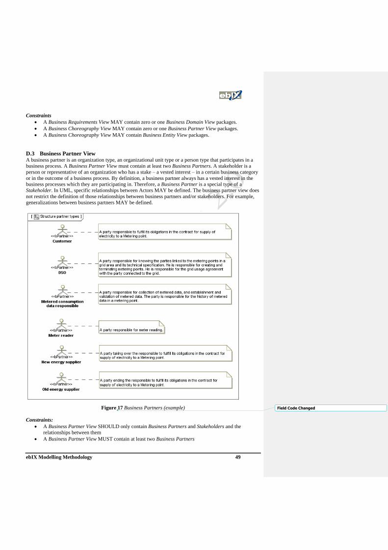
ebIX Modelling Methodology 49
Constraints
• A Business Requirements View MAY contain zero or one Business Domain View packages.
• A Business Choreography View MAY contain zero or one Business Partner View packages.
• A Business Choreography View MAY contain Business Entity View packages.
D.3 Business Partner View A business partner is an organization type, an organizational unit type or a person type that participates in a
business process. A Business Partner View must contain at least two Business Partners. A stakeholder is a
person or representative of an organization who has a stake – a vested interest – in a certain business category
or in the outcome of a business process. By definition, a business partner always has a vested interest in the
business processes which they are participating in. Therefore, a Business Partner is a special type of a
Stakeholder. In UML, specific relationships between Actors MAY be defined. The business partner view does
not restrict the definition of those relationships between business partners and/or stakeholders. For example,
generalizations between business partners MAY be defined.
Figure 17 Business Partners (example)
Constraints:
• A Business Partner View SHOULD only contain Business Partners and Stakeholders and the
relationships between them
• A Business Partner View MUST contain at least two Business Partners
Field Code Changed

ebIX Modelling Methodology 50
D.4 Business Entity View A business entity is a real-world thing having business significance that is shared between two or more
business partners in a collaborative business process (e.g. “order”, “account”, etc.). Within the business entity
view at least one, but possibly more business entities are described. Thus, the Business Entity View is
composed of one to many Business Entities.
Constraints:
• The Business Entity View MUST contain only Business Entities
• A Business Entity has zero or one UML State Diagram that expresses its behavior
• A UML State Diagram describing the lifecycle of a Business Entity SHOULD only contain Business
Entity States, Pseudo States, Final States or Transitions
• A Business Entity has zero or one Business Data View that describes its conceptual design
• Within a Business Data View UML Class Diagrams SHOULD be used
D.4.1 Business entity states The lifecycle of a business entity MAY be described as a flow of business entity states. Depending on the
importance of the business entity lifecycle, the lifecycle may or may not be included. A lifecycle is described
using a UML State Diagram. The lifecycle represents the different business entity states a business entity can
exist in. The lifecycle of a business entity consists of at least one business entity state. Therefore, the lifecycle
of a business entity is composed of one or more Business Entity States.
Figure 18 Business Entity State Diagram (example)
D.4.2 Business Data Views A business entity is a potential candidate for becoming a business document in later steps of the UMM. A
business data view MAY be used to elaborate a first conceptual design of a business entity. Hence, a Business
Entity is composed of zero to one Business Data Views. Within a business data view, A UML class diagram is
used to describe the assembly of a business entity. Thus, a Business Data View contains one-to-many UML
Class Diagrams.
D.5 Business Domain View The business domain view is used to discover business processes UseCases that are of relevance in a project.
A business process UseCase is executed by at least one (but possibly more) business partners. A business
partner might execute multiple business process UseCase s.
Field Code Changed
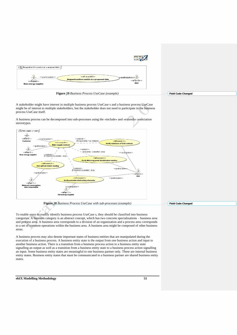
ebIX Modelling Methodology 51
Figure 19 Business Process UseCase (example)
A stakeholder might have interest in multiple business process UseCase s and a business process UseCase
might be of interest to multiple stakeholders, but the stakeholder does not need to participate in the business
process UseCase itself.
A business process can be decomposed into sub-processes using the «include» and «extends» association
stereotypes.
Figure 20 Business Process UseCase with sub-processes (example)
To enable users to readily identify business process UseCase s, they should be classified into business
categories. A business category is an abstract concept, which has two concrete specializations – business area
and process area. A business area corresponds to a division of an organization and a process area corresponds
to a set of common operations within the business area. A business area might be composed of other business
areas.
A business process may also denote important states of business entities that are manipulated during the
execution of a business process. A business entity state is the output from one business action and input to
another business action. There is a transition from a business process action to a business entity state
signalling an output as well as a transition from a business entity state to a business process action signalling
an input. Some business entity states are meaningful to one business partner only. These are internal business
entity states. Business entity states that must be communicated to a business partner are shared business entity
states.
Field Code Changed
Field Code Changed

ebIX Modelling Methodology 52
Figure 21 Business Process Activity (example)
Constraints:
• The Business Domain View package MUST include at least one Business Area.
• A Business Area package MUST include one or more Business Area packages or one or more Process
Area packages or one or more Business Process UseCases.
• A Process Area MUST contain one or more other Process Areas or at least one Business Process
• Business Partners MUST be connected with Business Process UseCases using the participates
relationship
• Stakeholders MUST be connected with Business Process UseCases using the isOfInterestTo
relationship
• A Business Process UseCase SHOULD be refined by a Business Process
• A Business Process, which has no Activity Partitions, MUST contain one or more Business Process
Actions and MAY contain Internal Business Entity States or Shared Business Entity States.
• An Activity Partition being part of a Business Process MUST contain one or more Business Process
Actions and MAY contain Internal Business Entity States.
D.6 Business Choreography View, The Business Choreography View is the second out of the 3 views of a UMM compliant business
collaboration model. The business choreography view describes the view how the business analyst sees the
process to be modelled. The requirements captured in the business requirements view serve as a basis for the
definition of a choreography of information exchanges. The business choreography view is a container for
three different artefacts that together describe the overall choreography of information exchanges.
Constraints:
• A Business Choreography View MUST contain at least one Business Collaboration View package.
• A Business Choreography View MUST contain at least one Business Transaction View package.
• A Business Choreography View MAY contain Business Realization View packages.
D.7 Business Transaction View A Business Transaction View is a container for artefacts that define a choreography leading to synchronized
states of business entities at both sides of the interaction. In fact, a business transaction view captures two
Field Code Changed

ebIX Modelling Methodology 53
different artefacts that define the business transaction. First, the business analyst defines concrete
requirements specifying the business transaction on a more general level by using business transaction
UseCases.
Figure 22 Business Transaction UseCase (example)
Second, he defines the flow of information exchanges in accordance to the requirements specified in this
container.
Figure 23 Business Transaction Activity (example)
Constraints:
• The Business Transaction View MUST contain exactly one Business Transaction UseCase, exactly
two Authorized Roles, and exactly two participates associations.
• A Business Transaction UseCase MUST be associated with exactly two Authorized Roles via
stereotyped binary participate associations.
• A Business Transaction UseCase MUST not include further UseCases.
• A Business Transaction UseCase MUST be included in at least one Business Collaboration UseCase.
• A Business Transaction UseCase MUST not be source or target of an extend association.
• Authorized Roles in a Business Transaction View must have a unique name within the scope of the
package, they are located in.
• A Business Transaction UseCase MUST be described by exactly one Business Transaction defined as
a child element of the Business Transaction UseCase.
• A Business Transaction MUST have exactly two partitions. Each of them MUST be stereotyped as
Business Transaction Partition. One partition MUST contain the Requesting Business Action and one
MUST contain the Responding Business Action.

ebIX Modelling Methodology 54
• A Business Transaction Partition MUST have a classifier, which MUST be one of the associated
Authorized Roles of the corresponding Business Transaction UseCase.
• The Business Transaction Partition of the requesting authorized role must contain exactly one
Requesting Business Action, one Requesting Information Pin and one Initial State. Furthermore there
MUST be at least two Final States in this Business Transaction Swim lane. Each of the Final States
MAY have a Business Entity Shared State as predecessor. One of the Final States SHOULD reflect a
Control Failure – this Final State SHOULD not have a predecessing Business Entity Shared State.
• If the transaction is a two‐way business transaction, then the partition of the requesting authorized role
MUST contain one-to-many Responding Information Pins.
• The Business Transaction Partition of the responding authorized role MUST contain exactly one
Responding Business Action and one Requesting Information Pin. If the transaction is a two‐way
business transaction, then the partition must contain one-to-many Responding Information Pins as
well. Otherwise, it is a one‐way business transaction and the responder partition must not contain a
Responding Information Pin.
• A Requesting Business Action MUST embed exactly one Requesting Information Pin and zero-to-
many Responding Information Pins.
• A Responding Business Action MUST embed exactly one Requesting Information Pin and zero-to-
many Responding Information Pins.
• Exactly one Transition MUST lead from the Requesting Information Pin embedded in the Requesting
Business Action to the Requesting Information Pin embedded in the Responding Business Action.
• Exactly one Transition MUST lead from each Responding Information Pin embedded in the
Responding Business Action to exactly one Responding Information Pin embedded in the Requesting
Business Action (only two way business transactions).
• Each Requesting Information Pin and each Responding Information Pin MUST either be source or
target of exactly one Transition.
• One Transition MUST lead from the Requesting Business Action to each Business Entity Shared State
and one Transition MUST lead from each Business Entity Shared State to a Final State. If no
Business Entity Shared States are used, one Transition MUST lead from the Requesting Business
Action to each Final State.
• Each Requesting Information Pin and each Responding Information Pin MUST have a classifier,
which MUST itself be a class and stereotyped as Business Information or as a child thereof.
D.7.1 States A business transaction is the basic building block to define a choreography of a business collaboration
between collaborating business partners. Communication in a business collaboration is about aligning the
information systems of the business partners. Aligning the information systems means that all relevant
business objects are in the same state in each information system. If a business partner recognizes an event
that changes the state of a business object, it initiates a business transaction to synchronize with the
collaborating business partner. It follows that a business transaction is an atomic unit that leads to a
synchronized state in both information systems.
A UMM business transaction takes place between two authorized roles. Each role must implement its own
business partner interface. It follows, that a UMM business transaction results in two state machines each
describing a business partner interface.
The UMM is used to specify a contractual flow of business document exchanges that business partners will
agree on. However, the flow as specified by UMM 1.0 requires human interpretation. This is due to the fact
that there exist ambiguous interdependencies between the business documents, the business transactions and
the business collaboration protocol. Business documents are exchanged leading to a business success or a
business failure of a business transaction. However, the same business document type is used to signal a
positive and a negative response. It is up to human interpretation how the business document content looks
like for a positive response and how it looks like for a negative response. Furthermore, the flow among
business transactions - which is specified by a business collaboration protocol - depends on the result of these

ebIX Modelling Methodology 55
business transactions. Unfortunately, the transition guards between the business transactions do not require
any formalism allowing traceability to the transaction results.
In order to overcome these limitations UMM 2.0 is extended by three concepts. Firstly, OCL invariants for a
positive response as well as for a negative response are introduced. An incoming response document is
checked against the OCL invariants to determine whether a business transaction succeeds or fails. Secondly,
the concept of business entity states into business transactions is incorporate. This means if the positive
invariant applies for a response document, the business entity manipulated by the business transaction is set to
an explicitly named business entity state before reaching the successful end state. Similarly, accordance with
the negative invariant results in another explicitly named business entity state before ending with a failure.
Thirdly, these business entity states are checked in the guard conditions of the control flow of a business
collaboration protocol by using the corresponding OCL function.
These UMM extensions lead to an unambiguous choreography that is understood by humans, but is also
automatically processable by machines. This is a prerequisite to derive unambiguous platform specific
protocols, such as a local choreography for each business partner in BPEL. The transformation of our UMM
extension to BPEL is part of future work.
D.8 Business Collaboration View The business collaboration view is a container for artefacts describing the flow of a complex business
collaboration between business partner types that may involve many steps. Similar to the business transaction
view, the Business Collaboration View captures two different artefacts as well. Once the business analyst has
specified the concrete requirements for a business collaboration by using business collaboration UseCases, he
is able to define the flow in accordance to the requirements defined in this container.
Figure 24 Business Collaboration UseCase (example)
Constraints:
• A Business Collaboration View MUST contain exactly one Business Collaboration UseCase.
• A Business Collaboration View MUST contain at least two Authorized Roles.
• A Business Collaboration UseCase MUST have at least two participates associations to Authorized
Roles contained in the same Business Collaboration View.
• Each Authorized Role contained in the Business Collaboration View MUST have exactly one
participates association to the Business Collaboration UseCase included in the same Business
Collaboration View.
• An Authorized Role MUST not have more than one participates association leading to a Business
Collaboration UseCase. (Note, different Authorized Roles with the same name may participate in
different Business Collaboration UseCases).
• A Business Collaboration UseCase MUST have at least one include relationship to either another
Business Collaboration UseCase or to a Business Transaction UseCase.

ebIX Modelling Methodology 56
A Business Collaboration View is used to define the business choreography of exactly one business
collaboration. This business choreography is specified by the concept of a Business Collaboration Protocol.
The requirements of a Business Collaboration Protocol are captured by a Business Collaboration UseCase.
Each Business Collaboration UseCase and its corresponding Business Collaboration Protocol are defined in
their own business collaboration view package. Accordingly, the Business Collaboration View is composed of
exactly one Business Collaboration UseCase and one Business Collaboration Protocol.
In UMM 2.0, role mapping between business collaboration authorized roles and either called business
transaction authorized roles or business collaboration protocol authorized roles is defined in the business
collaboration protocol. This role mapping is accomplished by information flows and specializations of
information flows, i.e. Initiating Flow and Responding Flow, between either business collaboration partitions
or nested collaborations and either business collaboration actions or business transaction actions. Using the
approach also enhances the business collaboration protocol by graphically illustrating the relationships
between authorized roles and the choreography of actions within a business collaboration protocol.
Figure 25 Business Collaboration Protocol (example)
Figure 26 Nested Business Collaboration Protocol (example)
Constraints:
• Exactly one Business Collaboration Protocol MUST be placed beneath each Business Collaboration
UseCase.
• A Business Collaboration Protocol MUST contain at least one Business Transaction Action or one
Business Collaboration Action.
• Each Business Transaction Action MUST call exactly one Business Transaction
• Each Business Transaction called by a Business Transaction Action MUST be placed beneath a
Business Transaction UseCase which is included in the Business Collaboration UseCase that covers
the corresponding Business Collaboration Protocol.

ebIX Modelling Methodology 57
• Each Business Collaboration Protocol called by a Business Collaboration Action MUST be placed
beneath a Business Collaboration Protocol UseCase which is included in the Business Collaboration
UseCase that covers the corresponding Business Collaboration Protocol.
• A Business Collaboration Protocol MUST contain at least two Business Collaboration Partitions.
• The number of Authorized Roles in the Business Collaboration View MUST match the number of
Business Collaboration Partitions in the Business Collaboration Protocol which is placed beneath the
Business Collaboration UseCase of the same Business Collaboration View.
• Each Authorized Role in the Business Collaboration View MUST be assigned to a Business
Collaboration Partition in the Business Collaboration Protocol which is placed beneath the Business
Collaboration UseCase of the same Business Collaboration View.
• Each Business Collaboration Partition MUST be classified by exactly one Authorized Role included
in the same Business Collaboration View as the Business Collaboration UseCase covering the
Business Collaboration Protocol containing this Business Collaboration Partition.
• A Business Collaboration Partition MUST be either empty or contain one or more Nested Business
Collaborations.
• Each Business Transaction Action MUST be the target of exactly one Initial Flow which source
MUST be a Business Collaboration Partition.
• Each Business Transaction Action MUST be the source of exactly one Initial Flow which target
MUST be either a Business Collaboration Partition or a Nested Business Collaboration.
• The Initial Flow sourcing from a Business Transaction Action and the Initial Flow targeting a
Business Transaction Action MUST NOT be targeting to, or sourcing from, the same Business
Collaboration Partition, nor targeting to a Nested Business Collaboration within the Business
Collaboration Partition.
• If a Business Transaction Action calls a two‐way Business Transaction, this Business Transaction
Action MUST be the source of exactly one Responding Flow which target MUST be a Business
Collaboration Partition.
• If a Business Transaction Action calls a two‐way Business Transaction, this Business Transaction
Action MUST be the target of exactly one Responding Flow which source MUST be either a Business
Collaboration Partition or a Nested Business Collaboration.
• The Responding Flow sourcing from a Business Transaction Action and the Responding Flow
targeting a Business Transaction Action MUST NOT be targeting to /sourcing from the same Business
Collaboration Partition, nor targeting to a Nested Business Collaboration within thisBusiness
Collaboration Partition.
• If a Business Transaction Action calls a one‐way Business Transaction, this Business Transaction
Action MUST NOT be the source of a Responding Flow and MUST NOT be the target of a
Responding Flow.
• The Responding Flow targeting a Business Transaction Action must start from the Business
Collaboration Partition / Nested Business Collaboration which is the target of the Initial Flow
starting from the same Business Transaction Action.
• The Responding Flow starting from a Business Transaction Action must target the Business
Collaboration Partition which is the source of the Initial Flow targeting to the same Business
Transaction Action.
• A Nested Business Collaboration MUST be the target of exactly one Initial Flow.
• A Nested Business Collaboration MAY be the source of a Responding Flow, but MUST NOT be the
source of more than one Responding Flow.
• A Business Collaboration Action MUST be the target of two or more Information Flows UML
standard: <<flow>>).
• A Business Collaboration Action MUST not be the source of an Information Flow.
• A Business Collaboration Action MUST not be the source and MUST not be the target of an Initial
Flow.
• A Business Collaboration Action MUST not be the source and MUST not be the target of a
Responding Flow.

ebIX Modelling Methodology 58
• A Business Transaction Action MUST not be the source and MUST not be the target of an
Information Flow (<<flow>>) that is neither stereotyped as Initial Flow nor as Responding Flow.
• A Nested Business Collaboration MUST not be the source and MUST not be the target of an
Information Flow that targets to / sources from a Business Collaboration Action.
• The number of Information Flows targeting a Business Collaboration Action MUST match the
number of Business Collaboration Partitions contained in the Business Collaboration Protocol that is
called by this Business Collaboration Action.
• Either an Authorized Role classifying a Business Collaboration Partition that is the source of an
Information Flow targeting a Business Collaboration Action MUST match an Authorized Role
classifying a Business Collaboration Partition in the Business Collaboration Protocol that is called by
this Business Collaboration Action or the Information Flow must be classified by an Authorized Role
classifying a Business Collaboration Partition in the Business Collaboration Protocol that is called by
this Business Collaboration Action.
D.9 Business Realization View The Collaboration Realization View describes the realization of a business collaboration UseCase for a
specific set of business partner types.
Business partners identified in the previous Business Requirements View must not directly be associated with
business collaboration UseCase s and business transaction UseCase s. In order to specify that a specific set of
business partners collaborate, we use the concept of a business realization. Each business realization is defined
in its own business realization view. Accordingly, the Business Realization View is composed of exactly one
Business Realization. A business realization realizes exactly one business collaboration UseCase . Each
business collaboration UseCase may be realized by multiple business realizations. Not each business
collaboration UseCase d (e.g. one that is nested within another one) needs to have a corresponding business
realization.
Two or more authorized roles participate in a business realization. Usually, the names of the authorized roles
participating in the business collaboration UseCase will be the names of the authorized roles in the business
realization realizing it. However, the authorized roles participating in the business collaboration UseCase and
the business realization will be defined in different namespaces. Furthermore, the number of actors
participating in a business collaboration UseCase must be the same as the number of actors participating in the
business realization realizing it.
In order to bind a business realization to the business partners executing it, business partners are mapped to
the authorized roles participating in the business realization. It is required that each authorized role of a
business realization (but not an authorized role in general) is target of exactly one mapsTo‐association from
a business partner. A business partner may play multiple authorized roles of a business realization.
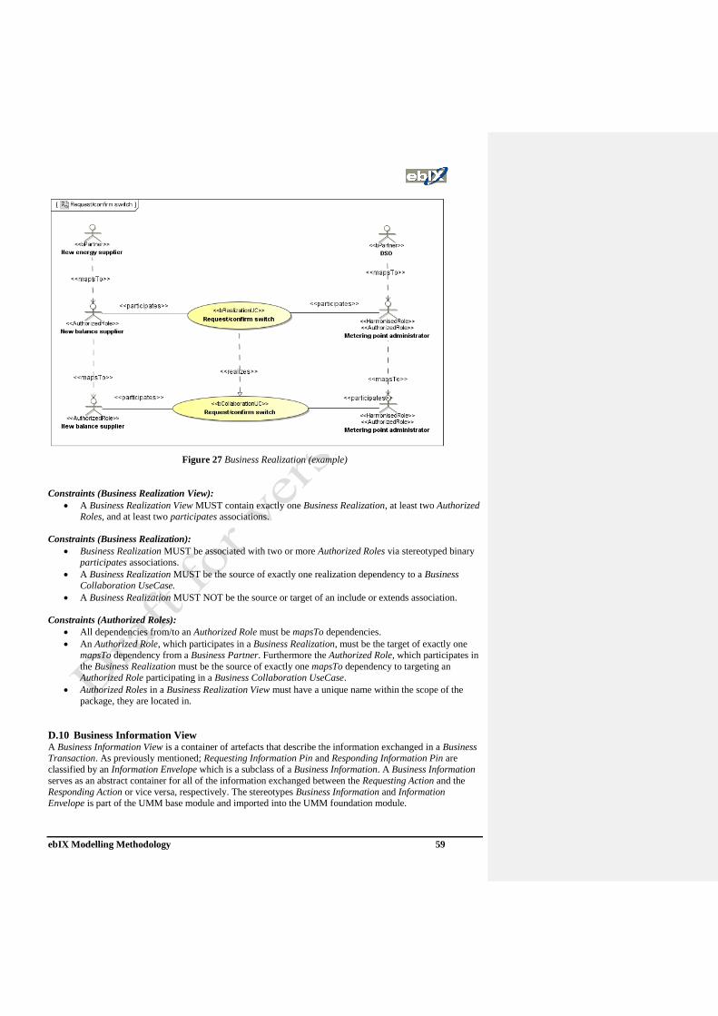
ebIX Modelling Methodology 59
Figure 27 Business Realization (example)
Constraints (Business Realization View):
• A Business Realization View MUST contain exactly one Business Realization, at least two Authorized
Roles, and at least two participates associations.
Constraints (Business Realization):
• Business Realization MUST be associated with two or more Authorized Roles via stereotyped binary
participates associations.
• A Business Realization MUST be the source of exactly one realization dependency to a Business
Collaboration UseCase.
• A Business Realization MUST NOT be the source or target of an include or extends association.
Constraints (Authorized Roles):
• All dependencies from/to an Authorized Role must be mapsTo dependencies.
• An Authorized Role, which participates in a Business Realization, must be the target of exactly one
mapsTo dependency from a Business Partner. Furthermore the Authorized Role, which participates in
the Business Realization must be the source of exactly one mapsTo dependency to targeting an
Authorized Role participating in a Business Collaboration UseCase.
• Authorized Roles in a Business Realization View must have a unique name within the scope of the
package, they are located in.
D.10 Business Information View A Business Information View is a container of artefacts that describe the information exchanged in a Business
Transaction. As previously mentioned; Requesting Information Pin and Responding Information Pin are
classified by an Information Envelope which is a subclass of a Business Information. A Business Information
serves as an abstract container for all of the information exchanged between the Requesting Action and the
Responding Action or vice versa, respectively. The stereotypes Business Information and Information
Envelope is part of the UMM base module and imported into the UMM foundation module.

ebIX Modelling Methodology 60
The current UMM foundation module does not mandate a specific business information modelling approach.
However, UMM strongly suggests using UN/CEFACT’s Core Components and Core Components Message
Assembly artefacts to model the business information. Because Core Components are syntax independent and
stereotyped, the usage of the UML Profile for Core Components is suggested within the Business Information
View.
Constraints:
• A Business Information View can contain Information Envelopes or any other document modelling
artefacts.
• Any artefact that is used in order to set the type of a Requesting Information Pin or a Responding
Information Pin in a Business Transaction MUST be of type Information Envelope.
D.11 PRIMLibrary The package with the stereotype “PRIMLibrary” contains the fixed set of CEFACT primitive types as defined
in the CCTS. The CEFACT primitive types are later on used to provide primitive types for the content
components (CON) and supplementary components (SUP) of the core data types (CDT) and qualified data
types (QDT) and are represented as UML classes with the stereotype “PRIM”.
D.12 ENUMLibrary The package with the stereotype “ENUMLibrary” contains the enumerations (code lists) that are used within
the model. Enumerations may later on used to restrict the content component (CON) of qualified data types
(QDT) and are represented as UML enumerations with the stereotype “ENUM”.
D.13 CDTLibrary The package with the stereotype “CDTLibrary” contains the fixed set of core component types as defined in
the CCTS. The core component types are later on used to derive qualified data types (QDT) by restriction and
are represented as UML classes with the stereotype “CDT” containing exactly one content component as a
UML attribute with the stereotype “CON” and one to many supplementary components as UML attributes
with the stereotype “SUP”.
D.14 QDTLibrary The package with the stereotype “QDTLibrary” contains the qualified data types (QDT) used within the
model. The qualified data types are derived by restriction from CDTs and are represented as UML classes
with the stereotype “QDT” containing exactly one content component as a UML attribute with the stereotype
“CON” and zero to many supplementary components as UML attributes with the stereotype “SUP”.
The fact that a QDT is derived from a CDT is represented as a UML dependency with stereotype basedOn
between a QDT and a CDT. The name of a QDT contains the name of the CDT it is based on prefixed by zero
to many semantic qualifiers separated with underscore as defined in the CCTS.
D.15 CCLibrary The package with the stereotype “CCLibrary” contains aggregate core components represented as UML
classed with stereotype “ACC” consisting of basic core components represented as UML attributes with
stereotype “BCC” and association core components represented as UML compositions with stereotype
“ASCC”. Aggregate core components are generic information objects as defined in the CCTS. The aggregate
core components (ACC) are later on used to derive aggregate business information entities (ABIE) by
restriction. The name of a class with stereotype “ACC” is the object class term as defined in the CCTS while
the names the attributes with stereotype “BCC” are the property terms and the target roles of compositions

ebIX Modelling Methodology 61
with stereotype “ASCC” are the representation terms (not the dictionary entry names respectively). The types
of the attributes with stereotype “BCC” are taken from the “CDTLibrary”.
D.16 BIELibrary The package with the stereotype “BIELibrary” contains aggregate business information entities represented as
UML classed with stereotype “ABIE” consisting of basic business information entities represented as UML
attributes with stereotype “BBIE” and association business information entities represented as UML
compositions with stereotype “ASBIE”. ABIEs are reusable information objects that are derived by restriction
from ACCs. The fact that an ABIE is derived from an ACC is represented as a UML dependency with
stereotype “basedOn” between an ABIE and an ACC. The names of ABIEs, BBIEs and ASBIEs contain the
name of the respective ACC, BCC and ASCC they are based on prefixed by zero to many semantic qualifiers
separated with underscore as defined in the CCTS.
Note that the classes with stereotype “ABIE” can be restricted by means of:
• restricted number of attributes (BBIEs) and compositions (ASBIEs),
• restricted multiplicity of attributes (BBIEs) and compositions (ASBIEs) and
• restricted data types using qualified data types (QDT) as restricted CDTs to type attributes (BBIEs).
D.17 DOCLibrary The package with the stereotype “DOCLibrary” contains the business information assembled from reusable
ABIEs as Root Schema Modules (RSM) to be exchanged in a given business scenario.
Business information from a “DOCLibrary” can be used as part of an UMM collaboration model within the
Business Information View.
ebIX Modelling Methodology 62
Appendix E Introduction to UML
This appendix is an extract of the OMG Unified Modeling Language (OMG UML), Superstructure, V2.1.2,
which can be found at [13]. It gives an overview of the possibilities UML gives when modelling business
processes within the energy industry and explains the artefacts used within ebIX models.
E.1 Terms and definitions Actor: An actor specifies a role played by a user or any other system that interacts with the
subject. An actor is represented by “stick man” icon with the name of the actor in the
vicinity (usually above or below) the icon.
Classifier: A classifier is a classification of instances. It describes a set of instances that have features
in common.
Guard: A condition that must be satisfied in order to enable an associated transition to fire. In a
simple transition with a guard, the guard is evaluated before the transition is triggered. In
compound transitions involving multiple guards, all guards are evaluated before a
transition is triggered, unless there are choice points along one or more of the paths. The
order in which the guards are evaluated is not defined. If there are choice points in a
compound transition, only guards that precede the choice point are evaluated according to
the above rule. Guards downstream of a choice point are evaluated if and when the choice
point is reached (using the same rule as above). In other words, for guard evaluation, a
choice point has the same effect as a state.
Operation: A service that can be requested from an object to effect behaviour. An operation has a
signature, which may restrict the actual parameters that are possible.
Package: A package is used to group elements, and provides a namespace for the grouped elements.
A package can be contained in other packages.
State A condition or situation during the life of an object during which it satisfies some
condition, performs some activity, or waits for some event.
Transitions: A relationship between two states indicating that an object in the first state will perform
certain specified actions and enter the second state when a specified event occurs and
specified conditions are satisfied. On such a change of state, the transition is said to fire.
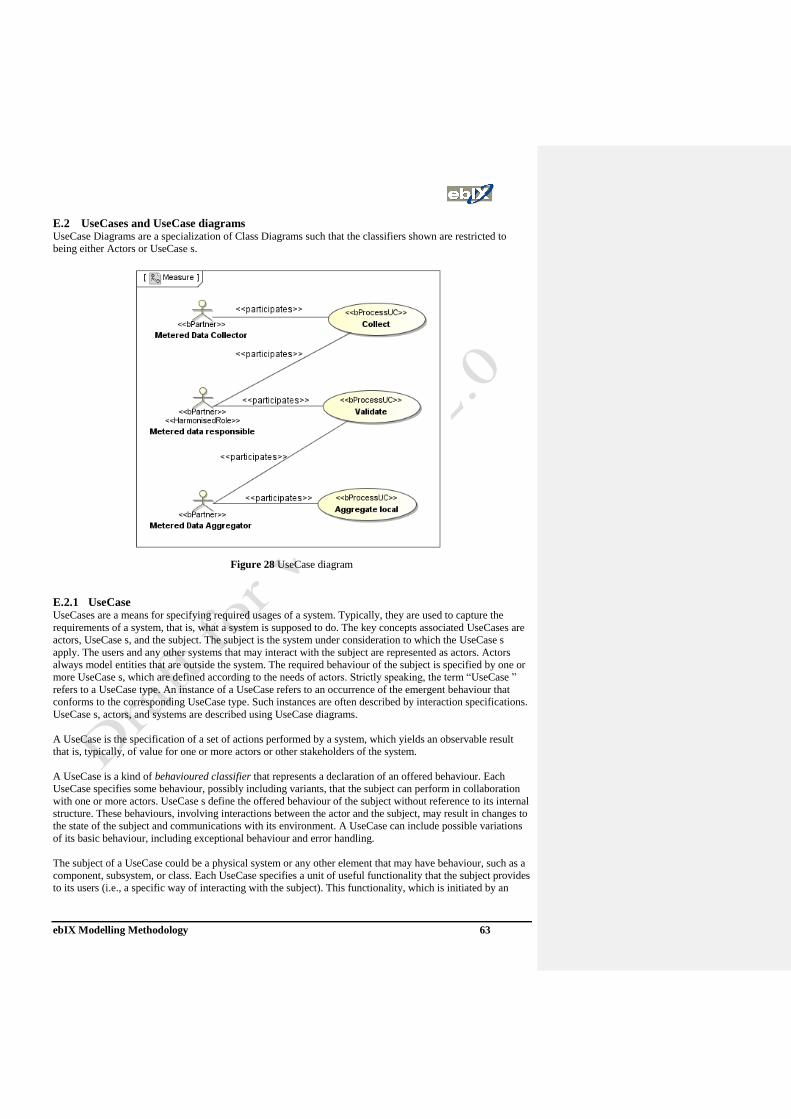
ebIX Modelling Methodology 63
E.2 UseCases and UseCase diagrams UseCase Diagrams are a specialization of Class Diagrams such that the classifiers shown are restricted to
being either Actors or UseCase s.
Figure 28 UseCase diagram
E.2.1 UseCase UseCases are a means for specifying required usages of a system. Typically, they are used to capture the
requirements of a system, that is, what a system is supposed to do. The key concepts associated UseCases are
actors, UseCase s, and the subject. The subject is the system under consideration to which the UseCase s
apply. The users and any other systems that may interact with the subject are represented as actors. Actors
always model entities that are outside the system. The required behaviour of the subject is specified by one or
more UseCase s, which are defined according to the needs of actors. Strictly speaking, the term “UseCase ”
refers to a UseCase type. An instance of a UseCase refers to an occurrence of the emergent behaviour that
conforms to the corresponding UseCase type. Such instances are often described by interaction specifications.
UseCase s, actors, and systems are described using UseCase diagrams.
A UseCase is the specification of a set of actions performed by a system, which yields an observable result
that is, typically, of value for one or more actors or other stakeholders of the system.
A UseCase is a kind of behavioured classifier that represents a declaration of an offered behaviour. Each
UseCase specifies some behaviour, possibly including variants, that the subject can perform in collaboration
with one or more actors. UseCase s define the offered behaviour of the subject without reference to its internal
structure. These behaviours, involving interactions between the actor and the subject, may result in changes to
the state of the subject and communications with its environment. A UseCase can include possible variations
of its basic behaviour, including exceptional behaviour and error handling.
The subject of a UseCase could be a physical system or any other element that may have behaviour, such as a
component, subsystem, or class. Each UseCase specifies a unit of useful functionality that the subject provides
to its users (i.e., a specific way of interacting with the subject). This functionality, which is initiated by an
ebIX Modelling Methodology 64
actor, must always be completed for the UseCase to complete. It is deemed complete if, after its execution, the
subject will be in a state in which no further inputs or actions are expected and the UseCase can be initiated
again or in an error state.
UseCase s can be used both for specification of the (external) requirements on a subject and for the
specification of the functionality offered by a subject. Moreover, the UseCase s also state the requirements the
specified subject poses on its environment by defining how they should interact with the subject so that it will
be able to perform its services.
The behaviour of a UseCase can be described by a specification that is some kind of Behaviour (through its
owned Behaviour relationship), such as interactions, activities, and state machines, or by pre-conditions and
post-conditions as well as by natural language text where appropriate. It may also be described indirectly
through a Collaboration that uses the UseCase and its actors as the classifiers that type its parts. Which of
these techniques to use depends on the nature of the UseCase behaviour as well as on the intended reader.
These descriptions can be combined.
E.2.2 Actor An Actor models a type of role played by an entity that interacts with the subject (e.g., by exchanging signals
and data), but which is external to the subject (i.e., in the sense that an instance of an actor is not a part of the
instance of its corresponding subject). Actors may represent roles played by human users, external hardware,
or other subjects. Note that an actor does not necessarily represent a specific physical entity but merely a
particular facet (i.e., “role”) of some entity that is relevant to the specification of its associated UseCase s.
Thus, a single physical instance may play the role of several different actors and, conversely, a given actor
may be played by multiple different instances. Since an actor is external to the subject, it is typically defined
in the same classifier or package that incorporates the subject classifier.
Style Guidelines Actor names should follow the capitalization and punctuation guidelines used for classes in
the model. The names of abstract actors should be shown in italics.
E.2.3 Extend relationship There are four basic relationships that can be used within UseCase diagrams:
• Relationship between Actors and UseCases:
o Association
• Relationship between Actors:
o Generalisation
• Relationship between UseCases:
o Include
o Extend
E.2.3.1 Association An association describes a set of tuples whose values refer to typed instances. An instance of an association is
called a link.
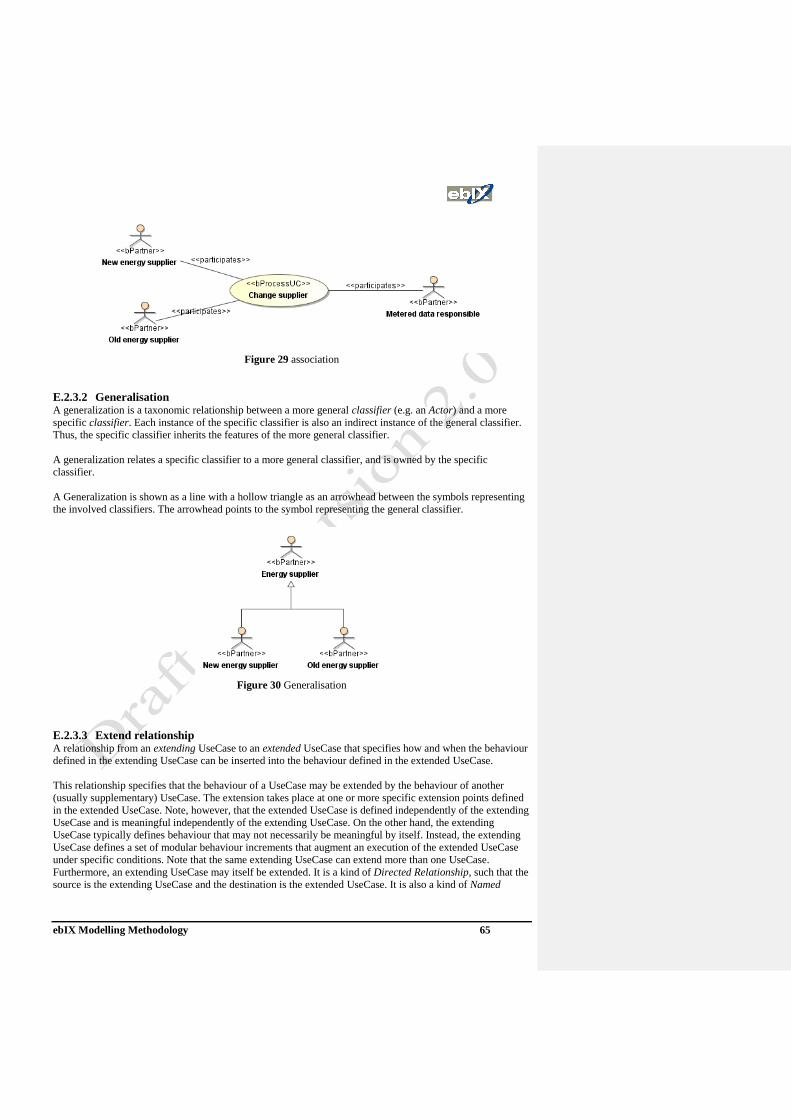
ebIX Modelling Methodology 65
Figure 29 association
E.2.3.2 Generalisation A generalization is a taxonomic relationship between a more general classifier (e.g. an Actor) and a more
specific classifier. Each instance of the specific classifier is also an indirect instance of the general classifier.
Thus, the specific classifier inherits the features of the more general classifier.
A generalization relates a specific classifier to a more general classifier, and is owned by the specific
classifier.
A Generalization is shown as a line with a hollow triangle as an arrowhead between the symbols representing
the involved classifiers. The arrowhead points to the symbol representing the general classifier.
Figure 30 Generalisation
E.2.3.3 Extend relationship A relationship from an extending UseCase to an extended UseCase that specifies how and when the behaviour
defined in the extending UseCase can be inserted into the behaviour defined in the extended UseCase.
This relationship specifies that the behaviour of a UseCase may be extended by the behaviour of another
(usually supplementary) UseCase. The extension takes place at one or more specific extension points defined
in the extended UseCase. Note, however, that the extended UseCase is defined independently of the extending
UseCase and is meaningful independently of the extending UseCase. On the other hand, the extending
UseCase typically defines behaviour that may not necessarily be meaningful by itself. Instead, the extending
UseCase defines a set of modular behaviour increments that augment an execution of the extended UseCase
under specific conditions. Note that the same extending UseCase can extend more than one UseCase.
Furthermore, an extending UseCase may itself be extended. It is a kind of Directed Relationship, such that the
source is the extending UseCase and the destination is the extended UseCase. It is also a kind of Named
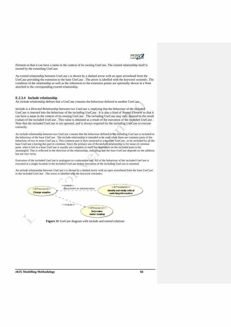
ebIX Modelling Methodology 66
Element so that it can have a name in the context of its owning UseCase. The extend relationship itself is
owned by the extending UseCase.
An extend relationship between UseCase s is shown by a dashed arrow with an open arrowhead from the
UseCase providing the extension to the base UseCase . The arrow is labelled with the keyword «extend». The
condition of the relationship as well as the references to the extension points are optionally shown in a Note
attached to the corresponding extend relationship.
E.2.3.4 Include relationship An include relationship defines that a UseCase contains the behaviour defined in another UseCase .
Include is a Directed Relationship between two UseCase s, implying that the behaviour of the included
UseCase is inserted into the behaviour of the including UseCase . It is also a kind of Named Element so that it
can have a name in the context of its owning UseCase . The including UseCase may only depend on the result
(value) of the included UseCase . This value is obtained as a result of the execution of the included UseCase .
Note that the included UseCase is not optional, and is always required for the including UseCase to execute
correctly.
An include relationship between two UseCase s means that the behaviour defined in the including UseCase is included in
the behaviour of the base UseCase . The include relationship is intended to be used when there are common parts of the
behaviour of two or more UseCase s. This common part is then extracted to a separate UseCase , to be included by all the
base UseCase s having this part in common. Since the primary use of the include relationship is for reuse of common
parts, what is left in a base UseCase is usually not complete in itself but dependent on the included parts to be
meaningful. This is reflected in the direction of the relationship, indicating that the base UseCase depends on the addition
but not vice versa.
Execution of the included UseCase is analogous to a subroutine call. All of the behaviour of the included UseCase is
executed at a single location in the included UseCase before execution of the including UseCase is resumed.
An include relationship between UseCase s is shown by a dashed arrow with an open arrowhead from the base UseCase
to the included UseCase . The arrow is labelled with the keyword «include».
Figure 31 UseCase diagram with include and extend relations

ebIX Modelling Methodology 67
E.3 Actions, Activities and Activity diagrams The focus of activity modelling is the sequence and conditions for coordinating lower-level behaviours, rather
than which classifiers own those behaviours. These are commonly called control flow and object flow models.
The behaviours coordinated by these models can be initiated because other behaviours finish executing,
because objects and data become available, or because events occur external to the flow
E.3.1 Activities Activity modelling emphasizes the sequence and conditions for coordinating lower-level behaviours, rather
than which classifiers own those behaviours. These are commonly called control flow and object flow models.
The actions coordinated by activity models can be initiated because other actions finish executing, because
objects and data become available, or because events occur external to the flow.
An action execution corresponds to the execution of a particular action. Similarly, an activity execution is the
execution of an activity, ultimately including the executions of actions within it. Each action in an activity
may execute zero, one, or more times for each activity execution. At the minimum, actions need access to
data, they need to transform and test data, and actions may require sequencing. The activities specification (at
the higher compliance levels) allows for several (logical) threads of control executing at once and
synchronization mechanisms to ensure that activities execute in a specified order. Semantics based on
concurrent execution can then be mapped easily into a distributed implementation. However, the fact that the
UML allows for concurrently executing objects does not necessarily imply a distributed software structure.
Some implementations may group together objects into a single task and execute sequentially - so long as the
behaviour of the implementation conforms to the sequencing constraints of the specification.
There are potentially many ways of implementing the same specification, and any implementation that
preserves the information content and behaviour of the specification is acceptable. Because the
implementation can have a different structure from that of the specification, there is a mapping between the
specification and its implementation. This mapping need not be one-to-one: an implementation need not even
use object-orientation, or it might choose a different set of classes from the original specification.
The mapping may be carried out by hand by overlaying physical models of computers and tasks for
implementation purposes, or the mapping could be carried out automatically. This specification neither
provides the overlays, nor does it provide for code generation explicitly, but the specification makes both
approaches possible.
An action represents a single step within an activity, that is, one that is not further decomposed within the
activity. An activity represents a behaviour that is composed of individual elements that are actions. Note,
however, that a call behaviour action may reference an activity definition, in which case the execution of the
call action involves the execution of the referenced activity and its actions (similarly for all the invocation
actions). An action is therefore simple from the point of view of the activity containing it, but may be complex
in its effect and not be atomic. As a piece of structure within an activity model, it is a single discrete element;
as a specification of behaviour to be performed, it may invoke referenced behaviour that is arbitrarily
complex. As a consequence, an activity defines a behaviour that can be reused in many places, whereas an
instance of an action is only used once at a particular point in an activity.
An action may have sets of incoming and outgoing activity edges that specify control flow and data flow from
and to other nodes. An action will not begin execution until all of its input conditions are satisfied. The
completion of the execution of an action may enable the execution of a set of successor nodes and actions that
take their inputs from the outputs of the action.
An activity is the specification of parameterized behaviour as the coordinated sequencing of subordinate units
whose individual elements are actions. There are actions that invoke activities (directly by
“CallBehaviorAction” or indirectly as methods by “CallOperationAction”.

ebIX Modelling Methodology 68
E.3.2 Actions An action is the fundamental unit of behaviour specification. An action takes a set of inputs and converts them
into a set of outputs, though either or both sets may be empty. This clause defines semantics for a number of
specialized actions, as described below. Some of the actions modify the state of the system in which the action
executes. The values that are the inputs to an action may be described by value specifications, obtained from
the output of actions that have one output (in StructuredActions), or in ways specific to the behaviours that use
them. For example, the activity flow model supports providing inputs to actions from the outputs of other
actions.
Actions are contained in behaviours, which provide their context. Behaviours provide constraints among
actions to determine when they execute and what inputs they have. The Actions clause is concerned with the
semantics of individual, primitive actions.
Figure 32 Activity with actions
E.3.3 OutputPin An output pin is a pin that holds output values produced by an action.
E.3.4 ActionInputPin An action input pin is a kind of pin that executes an action to determine the values to input to another.

ebIX Modelling Methodology 69
Figure 33 Actions with input pins and output pins
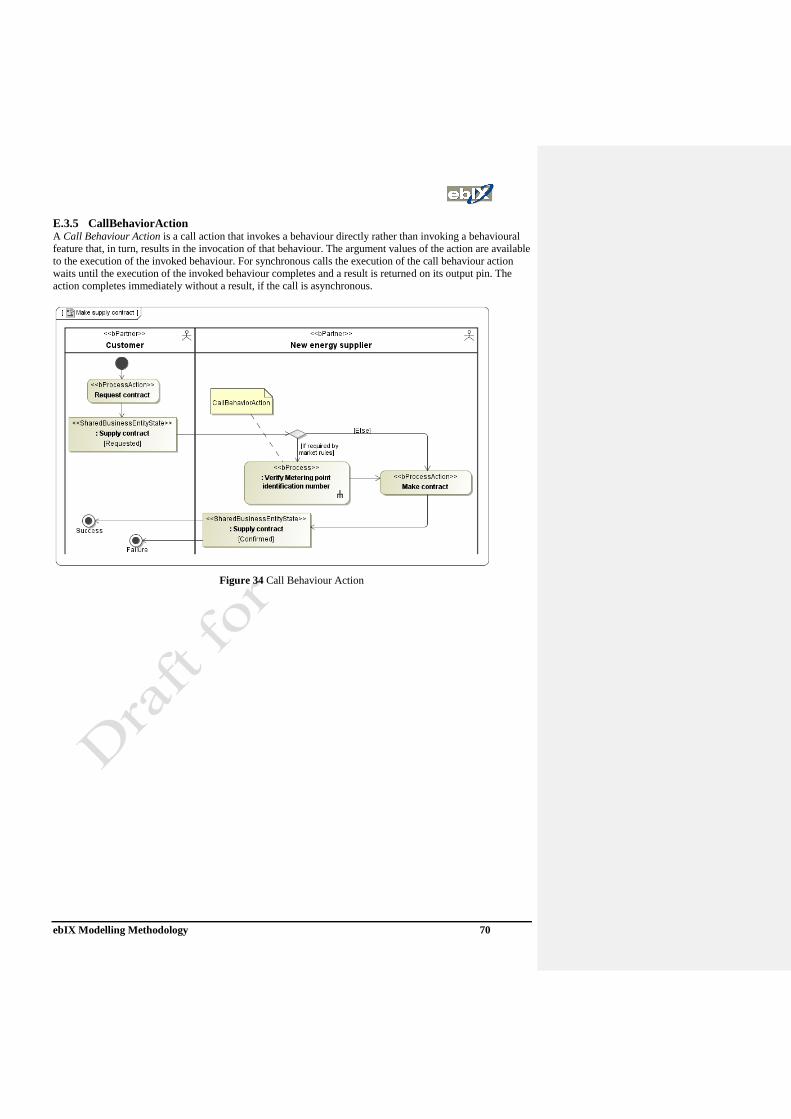
ebIX Modelling Methodology 70
E.3.5 CallBehaviorAction A Call Behaviour Action is a call action that invokes a behaviour directly rather than invoking a behavioural
feature that, in turn, results in the invocation of that behaviour. The argument values of the action are available
to the execution of the invoked behaviour. For synchronous calls the execution of the call behaviour action
waits until the execution of the invoked behaviour completes and a result is returned on its output pin. The
action completes immediately without a result, if the call is asynchronous.
Figure 34 Call Behaviour Action
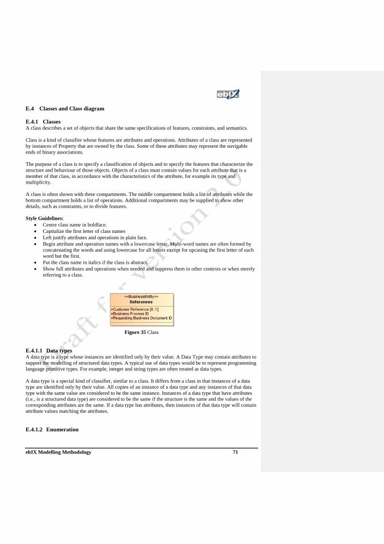
ebIX Modelling Methodology 71
E.4 Classes and Class diagram
E.4.1 Classes A class describes a set of objects that share the same specifications of features, constraints, and semantics.
Class is a kind of classifier whose features are attributes and operations. Attributes of a class are represented
by instances of Property that are owned by the class. Some of these attributes may represent the navigable
ends of binary associations.
The purpose of a class is to specify a classification of objects and to specify the features that characterize the
structure and behaviour of those objects. Objects of a class must contain values for each attribute that is a
member of that class, in accordance with the characteristics of the attribute, for example its type and
multiplicity.
A class is often shown with three compartments. The middle compartment holds a list of attributes while the
bottom compartment holds a list of operations. Additional compartments may be supplied to show other
details, such as constraints, or to divide features.
Style Guidelines:
• Centre class name in boldface.
• Capitalize the first letter of class names
• Left justify attributes and operations in plain face.
• Begin attribute and operation names with a lowercase letter. Multi-word names are often formed by
concatenating the words and using lowercase for all letters except for upcasing the first letter of each
word but the first.
• Put the class name in italics if the class is abstract.
• Show full attributes and operations when needed and suppress them in other contexts or when merely
referring to a class.
Figure 35 Class
E.4.1.1 Data types A data type is a type whose instances are identified only by their value. A Data Type may contain attributes to
support the modelling of structured data types. A typical use of data types would be to represent programming
language primitive types. For example, integer and string types are often treated as data types.
A data type is a special kind of classifier, similar to a class. It differs from a class in that instances of a data
type are identified only by their value. All copies of an instance of a data type and any instances of that data
type with the same value are considered to be the same instance. Instances of a data type that have attributes
(i.e., is a structured data type) are considered to be the same if the structure is the same and the values of the
corresponding attributes are the same. If a data type has attributes, then instances of that data type will contain
attribute values matching the attributes.
E.4.1.2 Enumeration
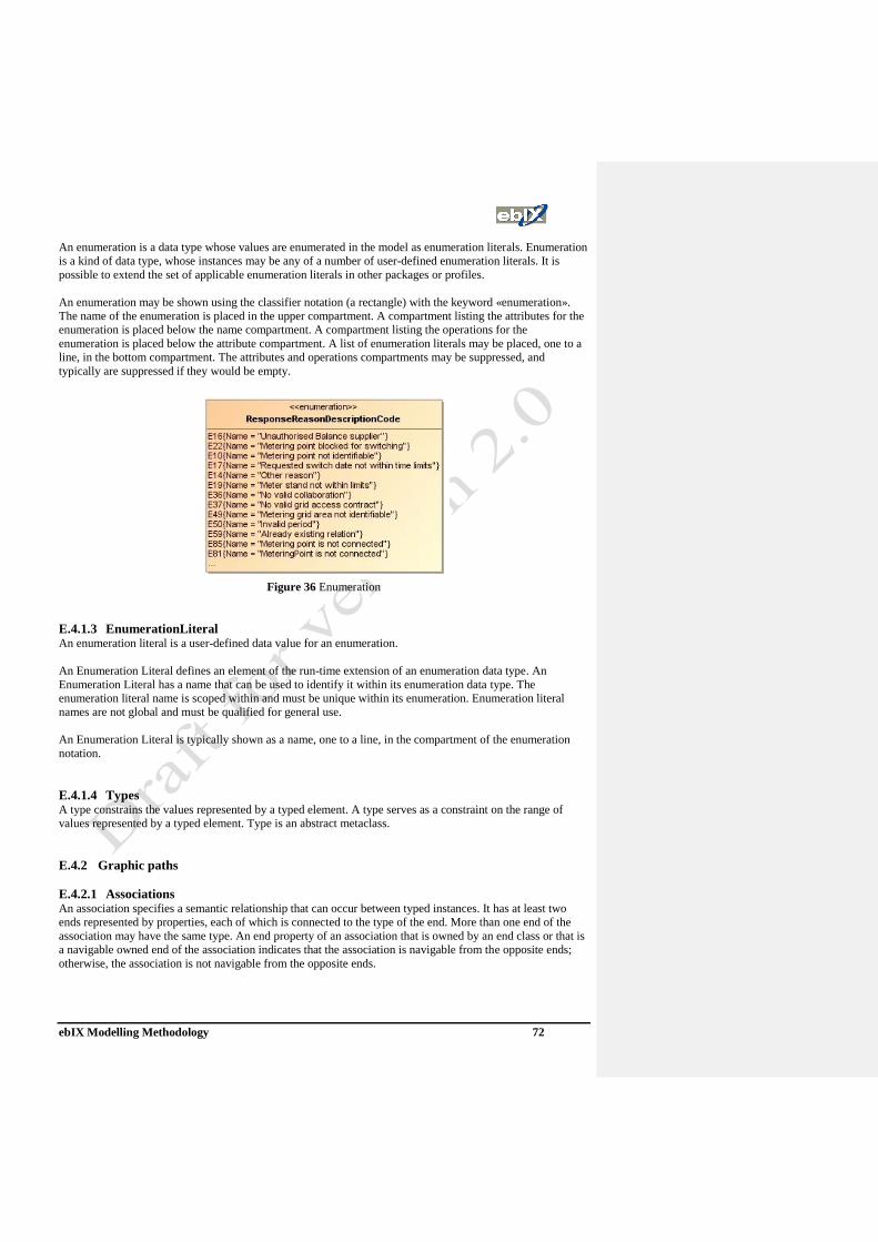
ebIX Modelling Methodology 72
An enumeration is a data type whose values are enumerated in the model as enumeration literals. Enumeration
is a kind of data type, whose instances may be any of a number of user-defined enumeration literals. It is
possible to extend the set of applicable enumeration literals in other packages or profiles.
An enumeration may be shown using the classifier notation (a rectangle) with the keyword «enumeration».
The name of the enumeration is placed in the upper compartment. A compartment listing the attributes for the
enumeration is placed below the name compartment. A compartment listing the operations for the
enumeration is placed below the attribute compartment. A list of enumeration literals may be placed, one to a
line, in the bottom compartment. The attributes and operations compartments may be suppressed, and
typically are suppressed if they would be empty.
Figure 36 Enumeration
E.4.1.3 EnumerationLiteral An enumeration literal is a user-defined data value for an enumeration.
An Enumeration Literal defines an element of the run-time extension of an enumeration data type. An
Enumeration Literal has a name that can be used to identify it within its enumeration data type. The
enumeration literal name is scoped within and must be unique within its enumeration. Enumeration literal
names are not global and must be qualified for general use.
An Enumeration Literal is typically shown as a name, one to a line, in the compartment of the enumeration
notation.
E.4.1.4 Types A type constrains the values represented by a typed element. A type serves as a constraint on the range of
values represented by a typed element. Type is an abstract metaclass.
E.4.2 Graphic paths
E.4.2.1 Associations An association specifies a semantic relationship that can occur between typed instances. It has at least two
ends represented by properties, each of which is connected to the type of the end. More than one end of the
association may have the same type. An end property of an association that is owned by an end class or that is
a navigable owned end of the association indicates that the association is navigable from the opposite ends;
otherwise, the association is not navigable from the opposite ends.

ebIX Modelling Methodology 73
A binary association is normally drawn as a solid line connecting two classifiers, or a solid line connecting a
single classifier to itself (the two ends are distinct). A line may consist of one or more connected segments.
An association declares that there can be links between instances of the associated types. A link is a tuple with
one value for each end of the association, where each value is an instance of the type of the end.
When one or more ends of the association are ordered, links carry ordering information in addition to their end
values.
Navigability means instances participating in links at runtime (instances of an association) can be accessed
efficiently from instances participating in links at the other ends of the association. The precise mechanism by
which such access is achieved is implementation specific. If an end is not navigable, access from the other
ends may or may not be possible. An open arrowhead on the end of an association indicates the end is
navigable.
Figure 37 Associations
An association end is the connection between the line depicting an association and the icon (often a box)
depicting the connected classifier. A name string may be placed near the end of the line to show the name of
the association end. The name is optional and suppressible. Various other notations can be placed near the end
of the line as follows:
• A multiplicity
• A property string enclosed in curly braces, e.g. {sequence} to show that the end represents a sequence
(an ordered bag).
Note that by default an association end represents a set.
An association may represent a composite aggregation (i.e., a whole/part relationship). Only binary
associations can be aggregations. Composite aggregation is a strong form of aggregation that requires a part
instance be included in at most one composite at a time. If a composite is deleted, all of its parts are normally
deleted with it.
An association with aggregationKind = shared differs in notation from binary associations in adding a hollow
diamond as a terminal adornment at the aggregate end of the association line. An association with
aggregationKind = composite likewise has a diamond at the aggregate end, but differs in having the diamond
filled in.
Figure 38 Compositions and Aggregations
E.4.2.2 Association Class
An Association Class is a model element that has both association and class properties. An Association
Class can be seen as an association that also has class properties, or as a class that also has association
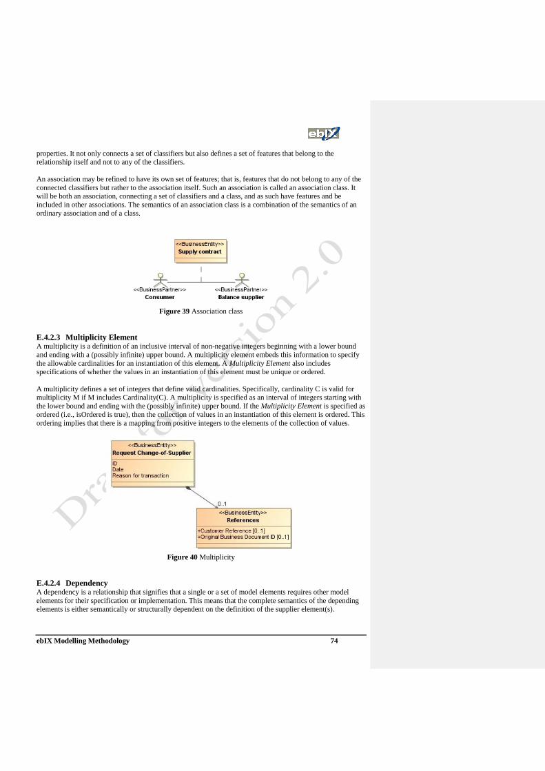
ebIX Modelling Methodology 74
properties. It not only connects a set of classifiers but also defines a set of features that belong to the
relationship itself and not to any of the classifiers.
An association may be refined to have its own set of features; that is, features that do not belong to any of the
connected classifiers but rather to the association itself. Such an association is called an association class. It
will be both an association, connecting a set of classifiers and a class, and as such have features and be
included in other associations. The semantics of an association class is a combination of the semantics of an
ordinary association and of a class.
Figure 39 Association class
E.4.2.3 Multiplicity Element A multiplicity is a definition of an inclusive interval of non-negative integers beginning with a lower bound
and ending with a (possibly infinite) upper bound. A multiplicity element embeds this information to specify
the allowable cardinalities for an instantiation of this element. A Multiplicity Element also includes
specifications of whether the values in an instantiation of this element must be unique or ordered.
A multiplicity defines a set of integers that define valid cardinalities. Specifically, cardinality C is valid for
multiplicity M if M includes Cardinality(C). A multiplicity is specified as an interval of integers starting with
the lower bound and ending with the (possibly infinite) upper bound. If the Multiplicity Element is specified as
ordered (i.e., isOrdered is true), then the collection of values in an instantiation of this element is ordered. This
ordering implies that there is a mapping from positive integers to the elements of the collection of values.
Figure 40 Multiplicity
E.4.2.4 Dependency A dependency is a relationship that signifies that a single or a set of model elements requires other model
elements for their specification or implementation. This means that the complete semantics of the depending
elements is either semantically or structurally dependent on the definition of the supplier element(s).
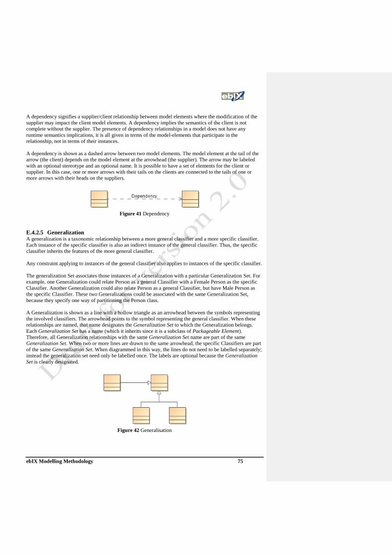
ebIX Modelling Methodology 75
A dependency signifies a supplier/client relationship between model elements where the modification of the
supplier may impact the client model elements. A dependency implies the semantics of the client is not
complete without the supplier. The presence of dependency relationships in a model does not have any
runtime semantics implications, it is all given in terms of the model-elements that participate in the
relationship, not in terms of their instances.
A dependency is shown as a dashed arrow between two model elements. The model element at the tail of the
arrow (the client) depends on the model element at the arrowhead (the supplier). The arrow may be labeled
with an optional stereotype and an optional name. It is possible to have a set of elements for the client or
supplier. In this case, one or more arrows with their tails on the clients are connected to the tails of one or
more arrows with their heads on the suppliers.
Figure 41 Dependency
E.4.2.5 Generalization A generalization is a taxonomic relationship between a more general classifier and a more specific classifier.
Each instance of the specific classifier is also an indirect instance of the general classifier. Thus, the specific
classifier inherits the features of the more general classifier.
Any constraint applying to instances of the general classifier also applies to instances of the specific classifier.
The generalization Set associates those instances of a Generalization with a particular Generalization Set. For
example, one Generalization could relate Person as a general Classifier with a Female Person as the specific
Classifier. Another Generalization could also relate Person as a general Classifier, but have Male Person as
the specific Classifier. These two Generalizations could be associated with the same Generalization Set,
because they specify one way of partitioning the Person class.
A Generalization is shown as a line with a hollow triangle as an arrowhead between the symbols representing
the involved classifiers. The arrowhead points to the symbol representing the general classifier. When these
relationships are named, that name designates the Generalization Set to which the Generalization belongs.
Each Generalization Set has a name (which it inherits since it is a subclass of Packageable Element).
Therefore, all Generalization relationships with the same Generalization Set name are part of the same
Generalization Set. When two or more lines are drawn to the same arrowhead, the specific Classifiers are part
of the same Generalization Set. When diagrammed in this way, the lines do not need to be labelled separately;
instead the generalization set need only be labelled once. The labels are optional because the Generalization
Set is clearly designated.
Figure 42 Generalisation

ebIX Modelling Methodology 76
E.4.3 Realization Realization is a specialized abstraction relationship between two sets of model elements, one representing a
specification (the supplier) and the other represents an implementation of the latter (the client). Realization
can be used to model stepwise refinement, optimizations, transformations, templates, model synthesis,
framework composition, etc.
Figure 43 Realisation
E.4.4 UN/CEFACT rules for message diagrams The following rules apply when making class diagrams for messages (Canonical model) based on the
UN/CEFACT Requirements Specification Mapping (RSM).
• All classes shall be normalized. That is to say:
1. An attribute shall represent a single piece of information
2. An attribute shall appear only once (i.e. it cannot be repeated)
3. An attribute shall have a distinct name
4. Each instance of a class must be uniquely identifiable
5. There is no positional dependence between the attributes
6. All attributes contribute to the definition of the class
• The only relationship permitted in a UMM compliant class diagram is a composite aggregation. All
compositions shall be unidirectional (directed composition).
• Target association end names shall be used.
• The multiplicity of an attribute is only used to indicate a conditional attribute with the convention
[0..1] that immediately follows the attribute name.
• The multiplicity of an association shall only appear at the target end of the association.
• An attribute shall use a core components data type
• Only XOR constraints are allowed between associations.
• Enumerations shall be used to identify code lists. In the canonical model an enumeration shall be used
to identify a restriction on a generic code list.
• No association classes or association names are permitted in the canonical model
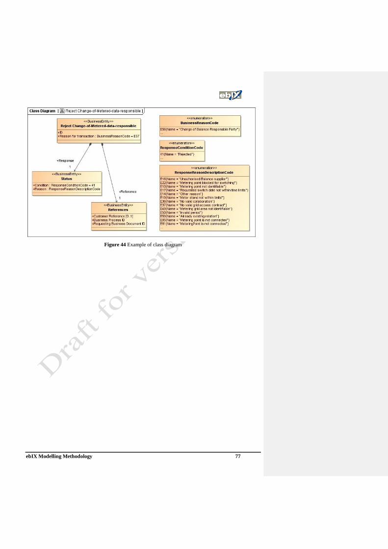
ebIX Modelling Methodology 77
Figure 44 Example of class diagram

ebIX Modelling Methodology 78
E.5 States The usage of states within ebIX models are under discussion not yet be used.
E.5.1 StateMachine The StateMachine package defines a set of concepts that can be used for modelling discrete behaviour through
finite state-transition systems. In addition to expressing the behaviour of a part of the system, state machines
can also be used to express the usage protocol of part of a system. These two kinds of state machines are
referred to here as behavioural state machines and protocol state machines.
Behavioural state machines
State machines can be used to specify behaviour of various model elements. For example, they can be
used to model the behaviour of individual entities (e.g., class instances). The state machine formalism
described in this sub clause is an object-based variant of Harel statecharts.
Protocol State machines
Protocol state machines are used to express usage protocols. Protocol state machines express the legal
transitions that a classifier can trigger. The state machine notation is a convenient way to define a
lifecycle for objects, or an order of the invocation of its operation. Because protocol state machines do
not preclude any specific behavioural implementation, and enforces legal usage scenarios of
classifiers, interfaces, and ports can be associated to this kind of state machines.
E.5.2 Protocol state machine
A protocol state machine is always defined in the context of a classifier. It specifies which operations of the
classifier can be called in which state and under which condition, thus specifying the allowed call sequences
on the classifier’s operations. A protocol state machine presents the possible and permitted transitions on the
instances of its context classifier, together with the operations that carry the transitions. In this manner, an
instance lifecycle can be created for a classifier, by specifying the order in which the operations can be
activated and the states through which an instance progresses during its existence.
The states of a protocol state machine (protocol states) present an external view of the class that is exposed to
its clients. Depending on the context, protocol states can correspond to the internal states of the instances as
expressed by behavioural state machines, or they can be different.
A protocol state machine expresses parts of the constraints that can be formulated for pre- and post-conditions
on operations. The translation from protocol state machine to pre- and post-conditions on operations might not
be straightforward, because the conditions would need to account for the operation call history on the
instance, which may or may not be directly represented by its internal states. A protocol state machine
provides a direct model of the state of interaction with the instance, so that constraints on interaction are more
easily expressed.
The protocol state machine defines all allowed transitions for each operation. The protocol state machine must
represent all operations that can generate a given change of state for a class. Those operations that do not
generate a transition are not represented in the protocol state machine.
Protocol state machines constitute a means to formalize the interface of classes, and do not express anything
except consistency rules for the implementation or dynamics of classes.
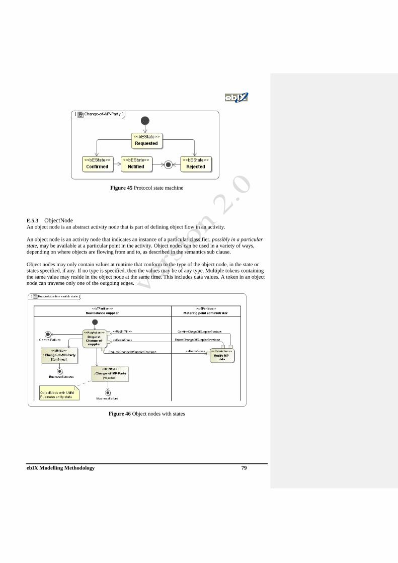
ebIX Modelling Methodology 79
Figure 45 Protocol state machine
E.5.3 ObjectNode
An object node is an abstract activity node that is part of defining object flow in an activity.
An object node is an activity node that indicates an instance of a particular classifier, possibly in a particular
state, may be available at a particular point in the activity. Object nodes can be used in a variety of ways,
depending on where objects are flowing from and to, as described in the semantics sub clause.
Object nodes may only contain values at runtime that conform to the type of the object node, in the state or
states specified, if any. If no type is specified, then the values may be of any type. Multiple tokens containing
the same value may reside in the object node at the same time. This includes data values. A token in an object
node can traverse only one of the outgoing edges.
Figure 46 Object nodes with states