Modelling Aqueous Corrosion || Modelling the Capacitive Behaviour of the Passive Film
17
MODELLINGTHECAPACITIVEBEHAVIOUR OF THEPASSIVEFILM R.OLTRA, P.BUCAILLE, M. INDRIANJAFY Laboratoire de Recherches sur la Reactivite des Solides URA 23 CNRS, BP138 21004 Dijon, France ABSTRA CT: In this paper, two different models of the capacitive behaviour of the passive film are presented. The first one considers the electrochemical cell as an "input-output" system which can be characterized by its impulse response. The second model describes the first step of the transient of electrical coupling process assuming that no direct faradaic process occurs during this stage. In other words, the transient cu"ent results solely of the charge and discharge of the double layer. In a second part, one comparison of these models with the experimentation is realized combining the pulsed laser depassivation technique and a multi-ring disk electrode which provides a validated experimental tool for evaluating of the theorical model. 1. Introduction Thispaper will bedevotedtoananalysisofthemodellingoftheroleofthepassive film during the transient steps encountered in localized corrosion processes, i.e. depassivation, unstable pitting. During transient steps (depassivation or repassivation),thepassive film interactswiththelocalizedunfilmedmetallicsurface. It hasbeenproposed to useanequivalentelectricalcircuitinordertodescribethe potentialchangeduringthepitinitiationandrepassivationwhichclearlyputforward the interaction between the passive surrounding surface and the pit area [1]. Nevertheless the modelling of the coupling current, assuming a pure capacitive behaviour,hasnotbeenperformedtoourknowledge. Inthispaper,afirstapproachwhichcanbecomparedtotheanalysisproposed by Isaacs [1] will be first presented, and in a second part the modelling of the coupling current has been tentatively attempted. From an experimental point of view, these two models have been checked by initiatingelectrochemical transient eventswithapulsedlaserbeamirradiatingawell-definedelectrode. First,thepulsedlasertechniqueallowsone to measuretheimpulseresponseh(t) ofanelectrochemicalcellduringatransientlocalizedcorrosionsituationassuming asan"input-output"system [2]. Secondly,thepulsedlasertechniquehasbeenusedtoallowthemeasurementof the local galvanic current as function of the surface in a local disturbance of a 279 K. R. Trethewey and P. R. Roberge (eds.), Modelling Aqueous Corrosion, 279-295. © 1994 Kluwer Academic Publishers.
Transcript of Modelling Aqueous Corrosion || Modelling the Capacitive Behaviour of the Passive Film

MODELLING THE CAPACITIVE BEHAVIOUR OF THE PASSIVE FILM
R.OLTRA, P.BUCAILLE, M. INDRIANJAFYLaboratoire de Recherches sur la Reactivite des SolidesURA 23 CNRS, BP13821004 Dijon, France
ABSTRACT: In this paper, two different models of the capacitive behaviour ofthe passive filmare presented. The first one considers the electrochemical cell as an "input-output" system whichcan be characterized by its impulse response. The second model describes the first step of thetransient of electrical coupling process assuming that no direct faradaic process occurs duringthis stage. In other words, the transient cu"ent results solely of the charge and discharge of thedouble layer. In a second part, one comparison of these models with the experimentation isrealized combining the pulsed laser depassivation technique and a multi-ring disk electrodewhich provides a validated experimental tool for evaluating of the theorical model.
1. Introduction
This paper will be devoted to an analysis of the modelling of the role of the passivefilm during the transient steps encountered in localized corrosion processes, i.e.depassivation, unstable pitting. During transient steps (depassivation orrepassivation), the passive film interacts with the localized unfilmed metallic surface.It has been proposed to use an equivalent electrical circuit in order to describe thepotential change during the pit initiation and repassivation which clearly put forwardthe interaction between the passive surrounding surface and the pit area [1].Nevertheless the modelling of the coupling current, assuming a pure capacitivebehaviour, has not been performed to our knowledge.In this paper, a first approach which can be compared to the analysis proposed
by Isaacs [1] will be first presented, and in a second part the modelling of thecoupling current has been tentatively attempted. From an experimental point ofview, these two models have been checked by initiating electrochemical transientevents with a pulsed laser beam irradiating a well-defined electrode.First, the pulsed laser technique allows one to measure the impulse response h(t)
of an electrochemical cell during a transient localized corrosion situation assumingas an "input-output" system [2].Secondly, the pulsed laser technique has been used to allow the measurement of
the local galvanic current as function of the surface in a local disturbance of a
279
K. R. Trethewey and P. R. Roberge (eds.), Modelling Aqueous Corrosion, 279-295.© 1994 Kluwer Academic Publishers.

280
capacitive electrode.These studies could be related to the debate recently presented about the
discussion of the modelling of the potential transients observed during the initiationof pitting [3,4].
2. Modelling of the hehaviour of a passive electrode
As presented in a detailed previous work [5,6], an electrochemical cell correspondingto a transient localized corrosion situation can be assumed as an "input-output"system which can be characterized by its impulse response h(t)[2]. The input signali,,,,(t) is the local current related to the localized corrosion. The output signal s(t)which is the measured parameter is dependent on the electrochemical conditions,Le. s(t) is the counter-electrode current (E imposed) or the corrosion potential (freecorrosion). In the two situations, the signal i(r,c{t) and s(t) are connected through thefollowing convolution product:
.s(t) = h(t)*ikc(t) = !ikc(t).h(t-'t)d'to
(1)
The experimental studies of the transient electrical coupling (v(t) or i(t) accordingto conditions) during the repassivation of a disk-ring electrode lead to the definitionof an equivalent electrical network (Figure 1) and to the expression of h(t)[4]. Thusin imposed potential conditions, considering the output current i(t) reaching thecounter-electrode loop, the impulse response is defined by:
h.(t) = !errl-.!)I ~ ~\ ~
(2)
and in free corroding conditions, the output signal v(t) is the change of the corrosionpotential Eoorr• Then, the impulse response is:
(3)
These impulse responses are identical to those obtained for a low-pass filter of
which the cut-off frequencies are respectively 1 and 12rr..ReCp 2rr..R.,Cp
The actual current ik:c involved during experimentation can be calculated from themeasured parameter, Le. the current reaching the potentiostat loop i(t) inpotentiostatic conditions or the free corrosion potential v(t) in free corroding

281
conditions. Using the relation (1), the input ilc.,(t) is given by the derivation of s(t):
t
~[h(t) * i/«) = ~[fi/«(t).h(t-t)dt]o
t
= i/cc(t).h(O) + fi/«(t).h'(t-t)dto
= i/cc.h(O) + i/«(t) * h '(t)
i(t)
vet)
Figure 1 - An equivalent electrical circuit for describing a localized corrosion situation:(a) in potentiostatic conditions (b) in free corrosion conditions
(4)

282
Taking into account the expression of the impulse response h(t), the local currenti1a: can be expressed as follows:
(5)
Thus, in free corroding conditions, the potential measured v(t), allows one to deducei'a:(t) with the help of the following relation:
i._-<t) = -C !![v(t)] - v(t)"" Pdt R,
(6)
This latter expression shows clearly the importance of the electrochemistry of thepassive surface through the value of Rt and c;, in free corroding situations.
3. Analytical modelling of the coupling current
3.1. INTRODUCTION
In this part, we will evaluate mathematically, with an analytical calculation, thetransient current and potential distribution in a cylindrical cell between a shortlydisturbed circular area and the passive concentric surrounding one if we consideronly their capacitive behavior in free potential condition. Our model describes onlythe first step of the transient electrical coupling process with the assumption that nodirect faradaic process occurs during the stage. In other words, the transient currentsresult solely from electrical processes of adsorption, charge and discharge of thedouble layer, both on the disturbed area and the passive one. The finite circularelectrode used in this problem is the commonly employed geometry forelectrochemical modelling.
3.2. ANALYTICAL MODEL
The geometry of the cell is illustrated in Figure 2. Two concentric and coplanarcircular areas of radius a and b represent respectively the disturbed surface and thesurrounding passive one. The thickness of the electrolyte is designated by h. Thepotential in an electrolyte medium must satisfy Laplace's equation
(7)
Taking into account the electrochemical polarization and the capacitive behaviour(Figure 3), the current density flowing through an electrode can be described with

the following boundary condition:
c34> _ 1 c c34>-~ - lC.(0cW0j) [Eo-4>l - ~~
z
Figure 2 - Cell Geometry
p
283
(8)
electrochemicalpolarization(linear)
CapacitiveEffects
I
Figure 3 - Equivalent electrical network for an metal-electrode interface
The first term of the second part contains the classical Wagner polarizationparameter "(<3cIl/c3j) and the open-circuit potential Eo, " being the electrolyticalconductivity of the liquid medium. This term depicts the linearized kinetic conditionfor stationary process. The second term, in which c denotes the interfacialcapacitance per area unit, describes the current flowing from the double layer. Inour analysis, we omit the polarization and consider only the second part of thegeneral boundary condition. By analogy with the Wagner polarization parameter

284
which has the dimension of a length, one can notice that the boundary condition forcapacitive behaviour contains another parameter l:!c, of which the unit is cm.s· l !Then, we apply the following boundary and initial conditions:
For the disturbed surface, z=O, Os;p s;a:
(9)
Cdis designates the specific capacitance of the disturbed surface and Et, its initialpotential just after the disturbing effect.
For the passive surrounding surface, z=O, a< p s;b
(Cl4l) _ cp Cl4laz ,=0 lC ~
(10)
Cp is the specific capacitance of the passive surface and Ep its initial potential. Forour analysis, we assume that these two capacitances are equal and take the value ofthe double layer: Cdis=Cp=C. The other boundaries of the cell, i.e. the envelope of thecylinder (p=b) and the upper plane of the cell (z=h) are assumed to be insulators.
3.3. MATHEMATICAL SOLUTION
An analytical solution of this problem can be derived from the galvanic problem ofconcentric circular anodic and cathodic areas. As presented in Table 1, the boundarycondition related to the capacitive behaviour can be identified to the linearizedexpression of the polarization if we apply on the first the Laplace's transform.One can notice that the transformed boundary condition of pure capacitive
behaviour takes the same expression as for polarization if we substitute the opencircuit potential Eo by E(I=o/s and the Wagner parameter lC(<3cI>/c3j) by l:!(sc). Then,according to the calculation of Gal-Or and Yahalom [7] and operating the substitution, the solution with the transformed potential becomes:

TABLE 1Mathematical solution
285
Originalexpressions ofthe boundaryconditions onthe electrode
variable
equation
Transformedboundaryconditions
GALVANIC CORROSION(linearized electrochemical
polarization)
lRANSIENT BEHAVIOUR(capacitive effects)
«p,t,S) = f4>(p,z,t).e -.stdto
(Laplace's transform)

286
Thus, performing the inverse Laplace's transform, we obtain the potential:
~(p,z,t) ;(~rEtis+(1-:: fp
(a, ~ p h-z. ICXR+_l.f _ h+2 - EdIs-E~ L,AR.JO(XR-).cosb(XR.-).exp[--WI&&U\A,R'-) t]
b R~ b b cb b
An being the coefficient of the serial expansion:
(12)
(13)
The current density on the electrode is obtained by derivation of the potentialdistribution and using Ohm's law:
The total current flow from a part of electrode at the time t is deduced as follows:
P> 2~
I(p"pz,t) ; f fj(p,z.,t)pdpd6P, 0
(15)
3.4 NUMERICAL EVALUAnON
The computation was carried out on an Epson PC 386DX33 with a numericalcoprocessor. The numbers of terms in the series were computed in order to reacha convergence of 10-7• Thus, The Figure 4 shows the time evolution of the potentialinside the electrochemical cell during a transient coupling. By analogy with thegalvanic corrosion problem, we can notice than the potential lines are moreconcentrated near disturbed-passive boundary.

t=O.25ms
287
Figure 4 . Time evolution of the potential distribution during a transient coupling(a=0.15 em; b=0.6 em; h=0.5 cm; C=45j.tF.em,2; K=4.5 mDl.em'l)

288
4. Experimental checking of the models
4.1. EXPERIMENTAL TECHNIQUE
4.1.1. Laser. Regarding the localized corrosion experiments the pulsed laserirradiation provides at least two original features:
- the depassivation can be considered as instantaneous, so then theperturbation and the resulting electrochemical transient can be described interms respectively of a Dirac excitation and an impulse response;- the geometrical parameters are well defined because the spot size and itslocation can be adjusted accurately.
This laser depassivation technique developed at the laboratory can be compared toa method used in electroanalytical chemistry for activating in situ glassy carbon electrode [8]. The laser source used in this work is a pulsed Nd-YAG laser at 1064 nm.For each impact, the energy of 1OMW.cm-2 provided during a short time of 25 ns isof the same order of magnitude than the values recommended to "clean" theaforementioned electrodes covered with thin oxide films [8]. By analogy with thegeneration of compressive stresses at the surface of metallic surfaces coated with afilm of water or oil, due to a thermoelastic effect, the pulsed laser irradiation of ametallic electrode protected from corrosion by a passive film has been analyzed interms of two contributions: a thermomechanical effect at the inner part of themetal-electrolyte interface resulting on a mechanical ejection of the passive film andcavitation in the electrolyte [9]. The electrochemical responses after the laser pulse,i.e. the corrosion current or the corrosion potential transients, allow one to checkthese two contributions.
4.1.2. Electrodes. As the laser beam can be accurately focused on the metallicsurface, all the experiments were conducted on electrodes ofwhich the depassivatedand the passive areas were separated and electrically insulated. The lateral surfaceof electrodes was covered with a cataphoretic paint providing an excellent protectionagainst infiltration of electrolyte between metal and insulator. The reducedgap(lOOJLm) between the disk and rings was filled up with a epoxy resin. Thesespecially designed dual electrodes permit the investigation of the nature of theelectrical coupling during localized corrosion as mentioned in previous publication[5] and they have also been tested during transient phenomena of corrosion such asdepassivation or initiation and repassivation of a pit [6]. Two kinds of speciallydesigned electrodes were used: a) a multi-ring electrode; and b) a dual electrode.
Multi-ring electrode
The electrode (304 stainless steel) is made of a central part (the disc, 3 mm in dia.)
289
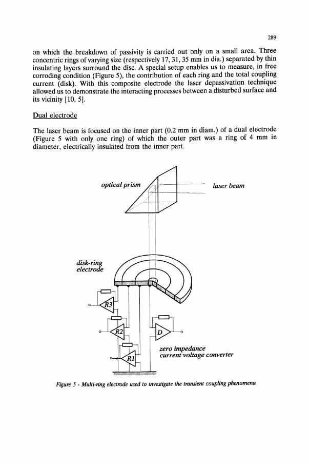
on which the breakdown of passivity is carried out only on a small area. Threeconcentric rings of varying size (respectively 17, 31, 35 mm in dia.) separated by thininsulating layers surround the disc. A special setup enables us to measure, in freecorroding condition (Figure 5), the contribution of each ring and the total couplingcurrent (disk). With this composite electrode the laser depassivation techniqueallowed us to demonstrate the interacting processes between a disturbed surface andits vicinity [10, 5].
Dual electrode
The laser beam is focused on the inner part (0.2 mm in diam.) of a dual electrode(Figure 5 with only one ring) of which the outer part was a ring of 4 mm indiameter, electrically insulated from the inner part.
laser beam
disk-ringelectrode
zero impedancecurrent voltage converter
Figure 5 -Multi-ring electrode used to investigate the transient coupling phenomena

290
4.2. IMPULSE RESPONSE OF A PASSIVE SURFACE
With an iron dual-electrode in HCl04, pHl, the current transient (coupling currentfcan be recorded simultaneously with the change of the potential of the electrode asshown in Figure 6. The laser pertubation was performed after passivation of thewhole electrode. In Figure 6, the current transient is a coupling current, involvingreactions on the two parts of the electrode. As the passive film is removed from thelaser irradiated disc, the charge for repassivation can be assumed to be supplied bythe surrounding surface.
A.p'
-6E-05
-1.2£-04
-J. 8£-04
-2.4£-04
-3£-04
-3.6£-04
-4.2£-04
-t 8E-04
-5.4E-04
I. 2E-03 2.4E-03 3.6E-03
V/ESS
.238
.226
. 21 ~
.202
,19
,178
.165
, 15~
,1.2
,13
t 8E-03 SEC
Figure 6 - Potential and current fluctuations recorded at free corroding conditions iron disk-ringelectrode (0.25 mm/2 mm) in HCI04 , pHl.
Taking into account the duration of the phenomena (about 1 millisecond inFigure 6), only a discharge of the capacitor associated with the passive surroundingring can be assumed. This behaviour has been previously analysed through the"input-output" model. The calculation of the current transient defined in equation(6) has been compared to the experimental measurement, shown in Figure 7. Agood agreement has been found proving the validity of the "input-output" model.
4.3. MEASUREMENT OF TIffi EFFECT OF TIlE COUPLING LENGTIl UPON TIlELOCAL CURRENT DIS1RIBU1l0N
To investigate the role of the capacitance, the multi-ring electrode was immersed ina borate buffer solution (pH=8.4;conductivity=4.5mO·1.cm·1). The laser energy wasfixed at 0.6 J.cm·2 in order to limit the perturbation of the passive interface to thedouble layer [11]. Figure 8 shows the typical results which are obtained in a borate
291
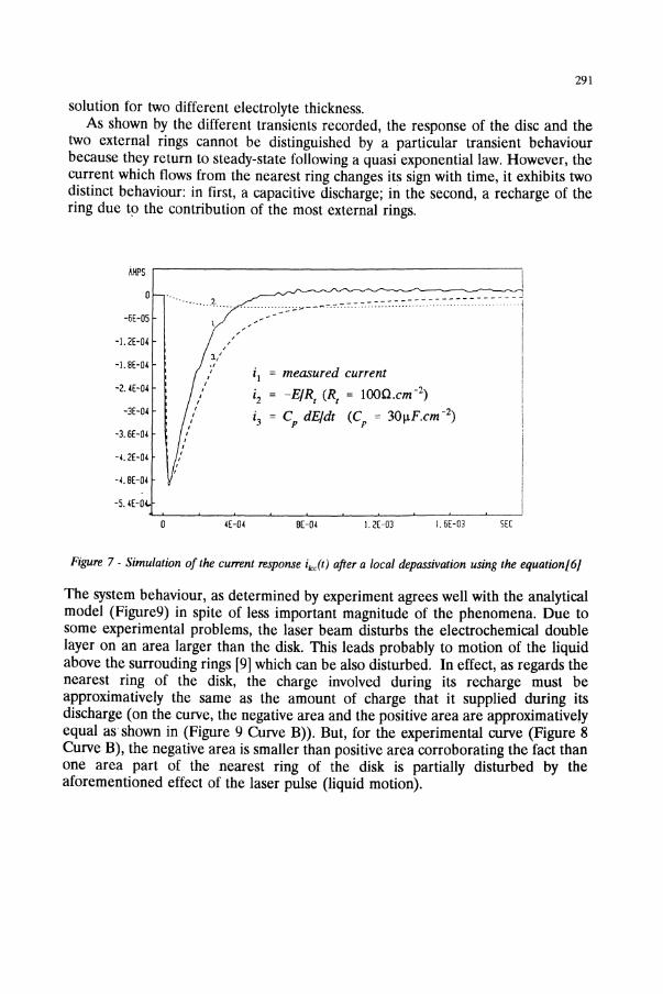
solution for two different electrolyte thickness.As shown by the different transients recorded, the response of the disc and the
two external rings cannot be distinguished by a particular transient behaviourbecause they return to steady-state following a quasi exponential law. However, thecurrent which flows from the nearest ring changes its sign with time, it exhibits twodistinct behaviour: in first, a capacitive discharge; in the second, a recharge of thering due tp the contribution of the most external rings.
iJU's .-----------------------,
i J = measured current
i2 = -EIRr
CRt = lOOn.cm -2)
i3= C dE/dt (C = 3011F.cm -2)
p r
-6E-OS
-].2E-04
-I. 8E-04
-2.4E-04
-3E-04
-3.6E-04
-( 2E-04
-4.8E-04
-5.4E-0
·· ..... 2
//,,
:3-/.,
:;:-: .... ----.- -
I
------------------~:·~·l
IIIII
I\
i
4E-04 8E-04 l.2E-03 I. 6E-03 SEC
Figure 7 - Simulation of the current response ilclt) after a local depassivation using the equation[6]
The system behaviour, as determined by experiment agrees well with the analyticalmodel (Figure9) in spite of less important magnitude of the phenomena. Due tosome experimental problems, the laser beam disturbs the electrochemical doublelayer on an area larger than the disk. This leads probably to motion of the liquidabove the surrouding rings [9] which can be also disturbed. In effect, as regards thenearest ring of the disk, the charge involved during its recharge must beapproximatively the same as the amount of charge that it supplied during itsdischarge (on the curve, the negative area and the positive area are approximativelyequal as shown in (Figure 9 Curve B)). But, for the experimental curve (Figure 8Curve B), the negative area is smaller than positive area corroborating the fact thanone area part of the nearest ring of the disk is partially disturbed by theaforementioned effect of the laser pulse (liquid motion).

292
electrolyte thickness = Icrn+0.40-r-------------.,
B
0.00
-E -0.40Q)......:J Ao-0.80
-1.20+----,----,---.-----10.0 14.0 28.0 42.0 56.0
time, ms
electrolyte thickness = 0.3crn+0.40.....---------------,
B
0.00
~
E~ -0.40cQ)
A......:J0
-0.80
-1.20+---......-----.-----r----j0.0 14.0 28.0 42.0 56.0
time, ms
Figure 8 - Experimental measurement of the current during a transient coupling for 2 electrolytethicknesses (A-disk (d =3 mm) B-Ring 1 (d = 17 mm) CoRing 2 (d =31 mm) D·Ring 3 (d =35
mm) K= 4.5 mOl.cm·I )

293
electrolyte thickness = Icm+0.40 ........---------------,
B
«E'E -0.40~::J()
-0.80
14.010.57.03.5-1.20...J.-..1L----r-----,...----,----!0.0
B
/0~/~
~c
j
time, ms
electrolyte thickness = 0.3cm+0.40
0.00
«E.: -0.40c:Q)~~
::J()
-0.80
-1.200.0 3.5 7.0 10.5 14.0
time. ms
Figure 9 - Time evolution of the cu"ent during a transient coupling computed with equation[26j for 2electrolyte thicknesses (A-disk (d =3 mm) B-Ring 1 (d = 17 mm) CoRing 2 (d = 31 mm) D-Ring 3
(d = 35 mm) C = 45,w.cm'z K = 4.5 m{)l.cm,l)
294
5. Conclusion
Two models have been described in this paper which confirm the role of thecapacitance of the passive film in localized corrosion. The "input-output" model canbe applied to unstable pitting and supports the capacitance model proposed byIsaacs [4] in opposition to the galvanic model [3]. Our approach allowed us todescribe with the same basic concept the transient behaviour in potentiostatic orfreely corroding conditions.The galvanic transient interaction during a local pertubation of the passive film
has been tentatively calculated from an analytical solution according to a calculationdefined for galvanic coupling in steady-state conditions.By means of the pulsed laser depassivation technique the two models have been
checked experimentally and the experiments fitted quite well the modellingapproach.
List of symbols
h(t)
h;(t)
hit)ikJt)s(t)Re
R,,,~
abhpztcI>(p,z,t)j(p,z,t)I(pI>P2,t)EdisErC
Cdis
cp
It
Jo, Jl
Xm
general impulse response describing the transient behaviourof an electrochemical cell, S-l or O.S-limpulse response corresponding to an electrochemical cell inimposed potential conditions, S-1impulse response in free corroding conditions, Alocalized corrosion current, Ameasured output signal in an electrochemical cell, A or Velectrolyte resistance, 0transfer resistance, Qtime constants, sdisk radius, emring radius, emelectrolyte thickness, emradial coordinates, emaxial coordinates, cmtime, spotential inside the cell, Vlocal current density, Acm-2
total current flow a part of the electrode, Apotential of the disturb area, Vpotential of the passive area, Vinterfacial capacitance of the electrode, F.cm-2
interfacial capacitance of the disturbed area, F.cm-2
interfacial capacitance of the passive area, F.cm-2
electrolyte conductivity, O-l.m-l
Bessel functions of frrst kind and order respectively 0 and 1zeroes of J1

295
REFERENCES
1. H.S. Isaacs and Y. Ishikawa, "Current and potential transients during localized corrosionof stainless steel", 1. Electrochem.Soc., Vol. 132, 1985, 1288-1293.
2. A. Papoulis, "Probability, RandomVariables, and stochastic processes", McGrawHiIl ed.,1965.
3. M.Hashimoto, S-Miyitjima and T.Murata, "A stochastic analysis of potential fluctuationduring passive film breakdown and repair on iron", Corrosion Sci., Vol. 33, 1992, 895-904.
4. H.S. Isaacs, Comments upon "A stochastic analysis of potential fluctuations duringpassive fIlm breakdown and repair on iron", Corrosion Sci., Vol. 34, 1993,525-528.
5. R Oltra, a. M. Indrianjafy, J.e. Colson, and M. Keddam, "Current and potentialtransients during mechanical depassivation of passive iron, Materials Science Forum, Vol.44&45, 1989, 259-270.
6. R Oltra and a.M. Indrianjafy, "Effect of electrical transient coupling phenomena onthe initiation of pits by a pulsed laser", J. Electrochem. Soc., Vol. 140, 1993,343-347.
7. L. Gal-Or, Y. Raz and 1. Yahalom, "Mathematical characterization of corrosioncurrents in local electrolytic cells", J. Electrochem. Soc, Vol. 120, 1973, 598-603.
8. M. Poon and R.L. McCreery, "In situ laser activation of glassy carbon electrodes",Anal.chem., Vol. 58, 1986,2745-2750.
9. R Oltra, a.M. Indrianjafy, and J.P. Boquillon, "Pulsed laser depassivation of metallicelectrodes in aqueous corrosive media", J. Phys. III, Vol. 3, 1991, 769774.
10. R Oltra, G.M. Indrianjafy, and M. Keddam, in Transient Techniques in CorrosionScience and Engineering, W.H. Smyri, D.D. Macdonald, and W.J. Lorenz, Editors, PV 89-1,p. 363, The Electrochemical Society Softbound Proceedings Series, Pennington, NJ(1989).
11. RK. Jaworski and RL. McCreery, "Laser-induced transients currents on glassy carbonelectrodes",1. Electrochem. Soc., Vol. 140, 1993, 1360-1365.