Modelling Aqueous Corrosion || Modelling Corrosion in Nuclear Systems
23
MODELLINGCORROSION IN NUCLEAR SYSTEMS Philippe BERGE Electricitl de France, 1-9 rue Nicolau 93407 Saint-Ouen France ABSTRACT. Numerous cases of corrosion have affected equipment in nuclear power plant. Once detected, it is necessary to be able to predict their evolution in order to determine appropriate corrective measures. Modelling is most often empirical and, if the number of cases is sufficient, may be supported by statistical evaluations. The study of the physical mechanisms involved is indispensable in order to provide guidelines for the models and to identify the parameters which must be taken into account. 1. Introduction Corrosionphenomenahavebeenencounteredinnuclearpowergenerationfromthe earliest stages, and for widely different reactor types, and have had a marked influenceonmaintenancecosts,andinsomecases,ontheindustrialdevelopment ofthesystemitself [1]. The numerous examples, onlya few ofwhich will be described in the present paper,haveanumberofcommonpoints.Forexample,lackofknowledge, at the designstage,ofthefactorswhichaffectthecorrosionofcomponentmaterialsunder normal or accidental operating conditions [2]. These factors often involve the contentsofresidual elements in themetalorofimpuritiesinthefluid,whichcan becomeconcentrated in contactwithheatexchangingsurfaces.Thisisthecasefor thephenomenawhich will bediscussedbelow,such as corrosion-erosionofsteelin hightemperaturewater,thecorrosionofsteelsincarbondioxide,orthecorrosion ofheatexchangertubes in steamgenerators by theelementspresentintheboiling water. Inotherexamples,thematerialmicrostructure,eitherresultingfromtheapplied heat treatment, or in the vicinity ofwelds, has been the principal cause of the corrosion observed. This is particularlytruefortheoccurrenceofstresscorrosion cracking in the heat affected zones of austenitic stainless steel welds in Boiling WaterReactors,orforthecrackingcaused by theprimarymediuminhighnickel austeniticalloys in PressurizedWaterReactors. Theessentialrequirement,oncethecorrosionphenomenonhasbeendetected, is tobeabletopredictitsdevelopmentwithtime.Theindustrialstrategywithregard tothesecomponents(run,repairorreplace) is basedentirelyontheabilitytomodel the phenomenon involved in order to predict its kinetics. This necessity for 65 K. R. Trethewey and P. R. Roberge (eds. J, Modelling Aqueous Corrosion, 65-87. © 1994 Kluwer Academic Publishers.
Transcript of Modelling Aqueous Corrosion || Modelling Corrosion in Nuclear Systems

MODELLING CORROSION IN NUCLEAR SYSTEMS
Philippe BERGEElectricitl de France,1-9 rue Nicolau93407 Saint-OuenFrance
ABSTRACT. Numerous cases of corrosion have affected equipment in nuclear power plant.Once detected, it is necessary to be able to predict their evolution in order to determineappropriate corrective measures. Modelling is most often empirical and, if the number of casesis sufficient, may be supported by statistical evaluations. The study of the physical mechanismsinvolved is indispensable in order to provide guidelines for the models and to identify theparameters which must be taken into account.
1. Introduction
Corrosion phenomena have been encountered in nuclear power generation from theearliest stages, and for widely different reactor types, and have had a markedinfluence on maintenance costs, and in some cases, on the industrial developmentof the system itself [1].The numerous examples, only a few of which will be described in the present
paper, have a number of common points. For example, lack of knowledge, at thedesign stage, of the factors which affect the corrosion of component materials undernormal or accidental operating conditions [2]. These factors often involve thecontents of residual elements in the metal or of impurities in the fluid, which canbecome concentrated in contact with heat exchanging surfaces. This is the case forthe phenomena which will be discussed below, such as corrosion-erosion of steel inhigh temperature water, the corrosion of steels in carbon dioxide, or the corrosionof heat exchanger tubes in steam generators by the elements present in the boilingwater.In other examples, the material microstructure, either resulting from the applied
heat treatment, or in the vicinity of welds, has been the principal cause of thecorrosion observed. This is particularly true for the occurrence of stress corrosioncracking in the heat affected zones of austenitic stainless steel welds in BoilingWater Reactors, or for the cracking caused by the primary medium in high nickelaustenitic alloys in Pressurized Water Reactors.The essential requirement, once the corrosion phenomenon has been detected, isto be able to predict its development with time. The industrial strategy with regardto these components (run, repair or replace) is based entirely on the ability to modelthe phenomenon involved in order to predict its kinetics. This necessity for
65
K. R. Trethewey and P. R. Roberge (eds. J, Modelling Aqueous Corrosion, 65-87.© 1994 Kluwer Academic Publishers.

66
prediction is particularly important in the nuclear industry, for which the safety ofthe installations demands a drastic limitation of the risks associated with the failureof certain components.A thorough understanding of the physical mechanisms underlying the observed
corrosion phenomenon is necessary in order to identify the factors which affect itskinetics. However, even in the very rare cases where such detailed knowledge isavailable, it is usually not sufficient on its own to develop a quantitative predictionmodel.The corrosion rate is more generally formulated by an empirical approachrequiring numerous laboratory tests, or by the analysis of examples observed in thefield, provided that they are sufficiently numerous. It is also only in the latter casethat statistically-based models can be developed, whose use will sometimes involvethe risk associated with the long term extrapolation of short time data.
2. High Temperature Oxidation
The simplest law describing the kinetics of uniform oxidation of a metal in amedium in which it is not soluble is given by a parabolic formula m = Av't, in whichthe weight of metal oxidized, m, in a time t, depends on a constant A, which can bedetermined experimentally, and which depends on the temperature, the alloycomposition, etc. This law reflects the fact that the oxide layer formed provides adegree of protection which is proportional to its thickness.In fact, this simple relationship rarely remains valid over a long period of time.
This rapidly became evident in the case of the zirconium alloys used for fuelcladding in water reactors, where the first stage of oxidation, corresponding toincreasing protection of the alloy, was followed by accelerated kinetics, related tometallurgical, physical and chemical factors, which, at least in the initial stages, weremodelled in an empirical manner.The same difficulty is encountered when it comes to predicting the thicknessallowance to be made in certain superheater tubes to take account of oxidation byhigh temperature steam. The double oxide layer formed, whose growth mechanismhas been widely studied [3J, often "multiplies" by stratification, due to chemical ormechanical changes. The total thickness at the end of life obviously depends on thenumber of strata formed (Figures 1 and 2).The most serious case involving an unsuspected transition in oxidation kineticsconcerned plain carbon steel components exposed to the carbon dioxide coolant inMagnox-type graphite-gas reactors, both in France and in Great Britain.The oxidation of steels in carbon dioxide at temperatures around 400 °C was
believed to follow a parabolic law, with the formation of a protective magnetitelayer. However, various factors, including residual elements in the steel, such assilicon, together with water vapour and carbon monoxide impurities in the gas,caused the expected growth mechanism to change to catastrophic oxidation.

Weight gain Oxide striation
67
-------
Exposure time
Figure 1 - Oxide Stratification Kinetics.
50 ~ml1li( .,
Figure 2 - Oxide Stratification· Multiple Layers on a Cr-Mo Steel in Superheated Steam.
68
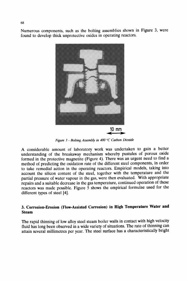
Numerous components, such as the bolting assemblies shown in Figure 3, werefound to develop thick unprotective oxides in operating reactors.
10 mm11II( ..
Figure 3 - Bolling Assembly in 400°C Carbon Dioxide
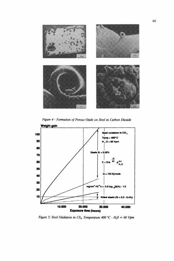
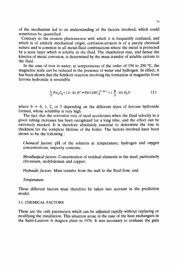
A considerable amount of laboratory work was undertaken to gain a betterunderstanding of the breakaway mechanism whereby pustules of porous oxideformed in the protective magnetite (Figure 4). There was an urgent need to find amethod of predicting the oxidation rate of the different steel components, in orderto take remedial action in the operating reactors. Empirical models, taking intoaccount the silicon content of the steel, together with the temperature and thepartial pressure of water vapour in the gas, were then evaluated. With appropriaterepairs and a suitable decrease in the gas temperature, continued operation of thesereactors was made possible. Figure 5 shows the empirical formulae used for thedifferent types of steel [4].
3. Corrosion-Erosion (Flow-Assisted Corrosion) in High Temperature Water andSteam
The rapid thinning of low alloy steel steam boiler walls in contact with high velocityfluid has long been observed in a wide variety of situations. The rate of thinning canattain several millimetres per year. The steel surface has a characteristically bright
69
Figure 4 - Formation of Porous Oxide on Steel in Carbon Dioxide
We ht 81n
40.000
Steel oxldellon In co.I
T~=4OO"C
H,O=60Vpm
ISIMla Si c 0.05%
I ~C=Kre RT po.-I H,O
Q.125Kjlmole
Imglcm'/10" h =·5.6 log Jll(%) • 113
I
10.000 20.000 30.000Expoture time (hours)
1-+---::>.....,:::.~---==__""""'=~--4-Killed ...... CSI ,. 0.2·0.4%)
50
40
90
80
70
60
30
100
Figure 5: Steel Oxidation in COJJ Temperature 400°C· Hp = 60 Vpm

70
appearance, with a dimpled, orange-peel, morphology, which micrographicexamination reveals a preferential attack of the pearlite (Figure 6).This phenomenon has also occurred extensively in the water-steam circuits of
nuclear boilers, typical examples being the feedwater inlet and economizer tubingin advanced gas-cooled reactors or the evaporator tubes in graphite-gas systems.Particularly serious cases have arisen in pressurized water reactors (PWR),
involving breakthrough in the J-shaped tubes of the steam generator feedwaterdistribution systems, and the ruptme of large diameter piping in the feedwatercircuits, one accident having led to the loss of human life and damage amounting toseveral millions of dollars.
Figure 6 - Bugey 5 drain pipe examination (divergent)
Numerous investigations of this phenomenon have been undertaken in Germany[5], Great Britain [6] and France [7, 8]. This work first of all provided an empiricalevaluation of the effects of the rate-controlling parameters, and subsequent studies
71
of the mechanism led to an understanding of the factors involved, which couldsometimes be quantified.Contrary to the erosion phenomenon with which it is frequently confused, andwhich is of entirely mechanical origin, corrosion-erosion is of a purely chemicalnature and is common in all metal-fluid combinations where the metal is protectedby a scale layer which is soluble in the fluid. The dissolution rate, and hence thekinetics of metal corrosion, is determined by the mass transfer of soluble cations tothe fluid.In the case of iron in water, at temperatures of the order of 150 to 250°C, the
magnetite scale can be reduced in the presence of water and hydrogen. In effect, ithas been shown that the Schikorr reaction involving the formation of magnetite fromferrous hydroxide is reversible
(1)
where b = 0, 1, 2, or 3 depending on the different types of ferrous hydroxideformed, whose solubility is very high.The fact that the corrosion rate of steel accelerates when the fluid velocity in a
given tubing increases has been recognized for a long time, and the effect can beextremely marked. It is therefore absolutely essential to determine the loss inthickness for the complete lifetime of the boiler. The factors involved have beenshown to be the following :
Chemical factors: pH of the solution at temperature; hydrogen and oxygenconcentrations; impurity contents;
Metallurgical factors: Concentration of residual elements in the steel, particularlychromium, molybdenum and copper;
Hydraulic factors: Mass transfer from the wall to the fluid flow; and
Temperature.
These different factors must therefore be taken into account in the predictionmodel.
3.1. CHEMICAL FACTORS
These are the only parameters which can be adjusted rapidly without replacing ormodifying the installation. This situation arose in the case of the heat exchangers inthe Saint-Laurent A magnox plant in 1976. It was necessary to evaluate the gain
72
which could be expected by modifying the water treatment, using either ammoniaor an amine, such as morpholine.A study of the mechanism involved led to the development of a formula enabling
the determination of the effect of pH and dissolved hydrogen content, making itpossible to predict the improvement which could be obtained. Since the oxidationrate is linear, the protection provided by the scale remains constant, albeit onlyslightin the case of rapid corrosion. Its dissolution rate is therefore equal to its rate offormation in contact with the metal. The latter is equal to roughly half of the overallcorrosion rate, the other half of the iron oxidized going directly into solution withoutcontributing to the formation of the scale layer. The rate of scale dissolution isrelated to the difference between Ceq, the concentration of ferrous iron soluble atequilibrium in reaction (1), and the concentration C1 in contact with the scale, viathe term K(Ceq - Ct ), K being the reaction rate constant, assuming first orderkinetics (as has been shown elsewhere).The corrosion rate, controlled by mass transfer, can be expressed in the form k(Ct
- Co), where k is the mass transfer coefficient in the fluid and Co is the concentrationof ferrous iron in the solution far from the wall. These two expressions can becombined to eliminate CI> which is unknown, to obtain the corrosion rate V:
with
V= Ceq-Co
..!K+..!2 k
(2)
(3)
These formulae thus show that the corrosion rate is proportional to the cube rootof the hydrogen partial pressure and enable quantification of the effect on corrosionof the pH in the liquid phase at high temperature.The variation of the ammonia concentration and the addition of morpholine in theSaint Laurent A feedwater enabled the predicted corrosion rate to be confirmed, bymeasuring the hydrogen produced as a function of the calculated high temperaturepH (Figure 8).The role of dissolved oxygen is very important (Figure 9), since the ferric ironformed from the ferrous iron in the presence of oxygen has a very low solubility.The release of soluble product is practically zero when the water contains largeamounts of dissolved oxygen. However, consideration of oxygen content cannotalways be readily applied. For concentrations less than 2 to 3 ppb, the modelsemployed are unable to account for this factor, since the measurements are toounreliable.

73
IFLOW ASSISTED CORROSION I
r (erosion· corrosion)~
Influonclng Poromo'o" J JFe" production at the
Oltyde I Solution Interlace
Waler Cheml~lry
(pH 0, IFell trensfer inloIne bulk water
Alloy Compo,>llICl'l(e r canll'lll l
T(!IIlIIlI,lhlll'
Vc• ~ (C
oq- Col ......__.J~
2K + k
C.o:rro51on ,.te
Vc = 2 K (Coq - C,l
l •
Hydrodyntlmlc~
(Flow veloclly geometry II
Corr06Ion_!J!~e
Vc = k (C 1 - Co)
Figure 7 - Schematic diagram of flow-assisted corrosion
H 2Produetion mglhr
a Plant test• Calculation
o ~0.2
7.06.56.0
(
~ NH. OHpH9.0 + 0.2..~ 9.1
- •9.3'\:_6morpholine pH 9.
~ /...ru
2
1
o5.5
0.2
0.6
Figure 8 . Results of tests in St Laurent A (1975-1977)

74
I II
,I
~'-I 1
-\- 5'35.8 Aeco<ding I;~s~ _
'-v-t.6m/s_ -pH-7
II
pL 40bitI =tl
\. /1-120"<: -=t13C,Mo44 y- 35mIs
'. pH-7 -
"-~~~ --1\-- ---{-
0- Converted Villues ~0.\
$peeifK: M••riel W.., bt.i 1000500
"gcmTti
0.5
10
100
50
\00 200 300 400 ,.gI1<g 500----+ O..yg~ Content
Figure 9 . Effect of Oxygen Content on Material Wear Due to Erosion-Corrosion [5]
3.2. METALLURGICAL FACTORS
While it is easy with the proposed mechanism to show tHat chromium, for example,which has very low solubility in a reducing medium, will counteract dissolution, inorder to evaluate the effect of chromium level in the steel, it is necessary to useempirical formulae based on experimental tests [9,10].In practice, for relatively severe conditions, a threshold of 0.1% Cr in the steelseems to be sufficient to prevent dissolution. This level of 0.1% Cr has been usedfor the specification of steels for water tubing where there is a risk of corrosionerosion.
3.3. HYDRAULIC FACTORS
The effect of the mass transfer coefficient k can also be determined from equation(2) above. This coefficient is often difficult to evaluate, due to the flow geometry.It can be determined by polarographic methods or by measuring thinning on plastermoulds in test installations [11].
3.4. TEMPERATURE
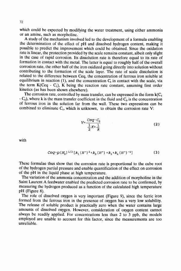
The marked effect of fluid temperature on the corrosion kinetics had beendetermined empirically. A more theoretical approach has also been made and showsgood agreement with the empirical values employed [12], Figure 10.
75
4.0
-,..
IZtl \40 1iO
TEMPERATURE, °cISO 200
Figure 10 - Theoretical culVes for tempemture dependence of erosion-corrosion taking into accountboth mass transfer (------) and kinetic (- - -) limitations to the rate, calculated at flow rates of 151,
302, 454, 605, 756 and 907 kg h·1 (n = 2) and with an activation energy of 67 k mole-I for the kineticrate{l2].
All of these different evaluations have been used to develop corrosion-erosionprediction codes. These are particularly necessary for determining when thephenomenon is likely to appear, together with its evolution when it does occur, andcan be used as a guideline for non-destructive inspection and the choice ofappropriate remedial action.These codes are based on the formulae described above for the hydrogen
concentration, the pH and the mass transfer (EDF Cicero code), and also on purelystatistical data, as in the case of the American code developed by EPRI. Extremelysatisfactory results have been obtained in applications based on case analyses.
4. Stress Corrosion Cracking
Stress corrosion cracking is a major cause of damage in many components in waterreactors, including fuel cladding, pipes and tubing in stainless steels and alloys, boltsand fittings in high strength alloys etc.In the primary coolant, certain alloys undergo stress corrosion cracking in the
absence of any chemical impurities. This is particularly the case for high strengthbolting materials, depending on the heat treatments employed (17-4 PH, Alloys X750 and A 286). However, the example which has been most widely publicized since

76
1959 is that of the nickel-rich Ni-Cr-Fe austenitic grade, Alloy 600.Despite warnings by Coriou in 1959, this alloy is widely used in pressurized water
reactors because of the compatibility of its thermal expansion coefficient with thatof ferritic steel, together with its good SCC resistance in chloride-containing media.It is employed for numerous components, while the welding materials, Inconels 82and 182, with closely similar compositions, have also revealed to be prone to SCCin laboratory tests.
Cases of SCC in Alloy 600 have been observed in PWR plants in the followingcomponents:
a. The steam generator tubing (Figures 11 and 12);b. The pressurizer heaters and instrumentation tubes; andc.More recently, in the reactor head penetration sleeves for the control rods (Figure13).
l'rirn!!fY Ji4l<Jtnm ilO«ot1:1:!n lltllC',killt!)Jtim~·I.1·~
TNrm1ns'"
m"d\lll
!'t1~$14l<
j~ ilO«ot1l:!n ~l'1l!C:kil1§
Figure 11 - Schematic diagram of a PWR steam generator

77
Figure: 12 - Steam generator tube: visual examination of the inner surfaceat the top of the rolled area, after specimen flattening.
An evaluation of the risk of cracking in this material has been undertaken for all ofthese components [13].Over the last three years or so, a large number of studies have been devoted to
the mechanism involved and have led to an empirical model for the onset ofcracking (initiation time) and the prediction of its development, based on crackpropagation rates.
4. 1. MECHANISMS
Numerous mechanisms are envisaged for see in Alloy 600. Although the mannerof modelling the corrosion often appears to be independent of the mechanisminvolved, in fact, the choice of the key parameters considered to be pertinent in themodel usually depends on an implicit mechanism, which therefore exerts a stronginfluence on the result.The mechanisms the most often considered for see in Alloy 600 are localized
dissolution [14, 15] and hydrogen embrittlement (16, 17]. Other theories have

78
appeared more recently, involving damage by internal grain boundary oxidation [18],by creep [19, 20], or by cleavage due to a specific interaction between plasticdeformation and corrosion [21, 22].
Thermal sleeve
Vessel headGIeel
\.
longitudinalcracks
Conlrol rod drive shaft
StainlessCladding
Ineonel 182buttering
Ineonel 182weld
" Int~onel 600penetration
Conical guide
Figure 13 - see ofAlloy 600 in PWR plants: vessel head penetration
4. 1. 1.Localized dissolution. The emergence of slip steps at the crack tip leads toperiodic breakdown of the passive film, causing accelerated metal dissolution,followed by repassivation. The periodic repetition of this sequence of events directlycontrols the rate of crack advance. Calculations lead to a relation which predicts thatthe propagation rate Vf can be determined if the repassivation kinetics of thematerial (described by a t-n law) are known, together with the local strain rate e, viathe relation Vf = A(n)e-o. This theory has two essential consequences:
- The predominant mechanical parameter is the strain rate and not the stress, whichacts only indirectly via the rate of deformation which it produces.

79
- The phenomenon of crack growth results directly from a loss of matter due todissolution, and does not involve brittle fracture. The dissolution is controlledessentially by e and by the chemical composition of both the material and themedium.
Consequently, modelling of the phenomenon must be based on the variation of thelocal strain rate with mechanical loading, and requires data on the value of theexponent n and the function A(n), as a function of the nature of the material andthe physical-chemical conditions of tbe medium.For Alloy 600, the repassivation kinetics have been quantified in the primarymedium at 360°C and the predicted relation between strain rate and crackpropagation rate has been verified [23], providing an argument in favour of this typeof mechanism.
4.1.2.Hydrogen-induced cracking mechanism. The hydrogen produced by reduction ofthe water, which oxidizes the metal, can induce different embrittlement phenomena:
- by internal pressure development [24]: the hydrogen transported in the lattice inatomic form recombines locally at micro-cavities, generating high internal pressures,which promote cracking. In a recent variant of this mechanism, an identical role hasbeen attributed to bubbles of methane observed in Alloy 600 cracked in the primarymedium at 360°C [16, 17]. The methane is assumed to form at the grain boundariesby reaction between the hydrogen and carbon in solution.
- by lowering the cohesive energy of the lattice. The cohesive energy can be loweredeither at the surface (adsorption [25]) or within the volume of the material, due tothe presence of hydrogen, which concentrates in regions of high triaxial stress [26,27]. Measurements have shown that hydrogen effectively accumulates in Alloy 600under stress in the primary medium [28].
- by local increase in plasticity. This is particularly the theory of Pei [29], who showsthat, by facilitating shear, hydrogen can promote dislocation pile-ups, leading tomore rapid attainment of the local cleavage stress.
These different hydrogen embrittlement theories are complex, and lend themselvesless readily to operational modelling, but although no serious attempt has beenmade for Alloy 600, this mechanism is often evoked. Their principal practicalinterest is the assertion that the key mechanical parameter is probably the stress,which produces disbonding. However, the strain rate can also have an independenteffect, via the hydrogen transport phenomena. In this case, crack growth is no longerdue to the loss of matter, but to brittle fracture, and the corrosion has only a veryindirect role, by producing hydrogen, part of which can cause embrittlement.
80
4.1.3./ntemal oxidation mechanism. According to Scott [18], sec in Alloy 600 is dueto internal oxidation at grain boundaries. The predominant mechanism in this caseis the diffusion of oxygen from the water, and fracture is assumed to be due eitherto embrittlement by an intergranular layer of oxygen, or to the indirect effect of highpressure CO2 bubbles formed by reaction between the oxygen and carbon in solutionat the grain boundaries. The activation energy for this mechanism is unknown andits practical impact is not clear.
4.1.4.Creep damage. This mechanism [19,20] is based on the fact that intergranuJarfailure by pure creep can be observed in Alloy 600 in an inert environment at 360or 400 0c. According to Was [19], the intergranular sec failure mode and the creepdeformation mode are identical: formation and coalescence of grain boundary voids,leading to intergranular rupture. The effect of the medium would be simply toaccelerate creep.
4.1.5. Cleavage due to interaction between the medium and plastic strain. This model,initially developed for the transgranular cracking of stainless steels, and recentlyapplied to intergranular sec in Alloy 600, predicts cleavage either at the grainboundaries, or in a zig-zag path in their vicinity. The cleavage is caused by thecombination of the macroscopic stress and local stress fields due to dislocation pileups at obstacles near the grain boundary. A local increase in plasticity due to theenvironment (dissolution and hydrogen) is necessary to produce the effect. The zigzag cracking near grain boundaries predicted by this model has effectively beenobserved in Alloy 600 in the primary medium [22]. Although modelling of themechanism is still incomplete, what are probably the most important practicalconsequences are the prediction of cracking by cleavage, with in this case adominant role of the stress, and a material plasticity locally modified by the medium.
4.2. CRACK INITIAnON
The factors which determine the crack initiation time are the applied stress, thetemperature, the mode and extent of chromium carbide precipitation, the grain size,the amount of cold work and the hydrogen content of the medium.
The empirical formula used is of the form [26]:
(4)
Attempts to justify the stress exponent, whose value of 4 is not universally accepted,are not very convincing. The value of the activation energy has not been determinedon the basis of theoretical considerations. A tentative formulation for the role ofhydrogen has been made in terms of its effect on the dissolution of iron, but doesnot confirm the (H2)1f3 law observed experimentally over a wide range of
81
concentrations [27]. The formula used is essentially empirical and has been appliedto all the components in order to evaluate the risk of cracking during the plannedlifetime of a plant.For a hydrogen content of 30-50 cc kg-! and for the operating conditions of the
primary medium, the formula becomes:
-22000
t =ka-4 e~r(5)
where a is in MPa and the coefficient k has a value between 0.02 and 0.2. Inparticular, k can vary by a factor of 10 for different alloy structures, principally withregard to the chromium carbide distribution [28]. There is a large uncertainty in thisevaluation, since the stress level incorporates residual stresses in the material, whichcan have variable degrees of cold work.
4.3. CRACKING OF STEAM GENERATOR TUBES IN THE PRIMARY MEDIUM
4.3.1. Crack initiation. While qualitative and comparative studies can use theempirical formula given above, a satisfactory prediction of the variation with timeof the degree of cracking in a steam generator requires a statistical approach, suchas that introduced in a code developed by Electricite de France [29]. The scatterobserved in the initiation times for longitudinal cracks in the region of high residualstress at the transition between the expanded zone inside the plate and the tubeunaffected by this operation can be closely described by the Weibull distribution law[30]. With appropriate adjustments based on abundant inspection data, it is thuspossible to obtain an accurate prediction of the variation of damage with time.
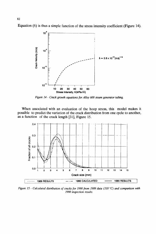
4.3.2. Crack propagation. For the thin-walled steam generator tubes, the propagationof longitudinal cracks through the thickness occurs in a time which is very shortcompared to that for initiation. It has been shown that short cracks, even whenextending through the thickness, represent neither a significant leak nor a risk ofsudden failure of the tube, provided that their length remains less than 15 to 16 mm.In contrast, longitudinal growth can lead to unacceptable crack lengths and the rateof propagation in this direction is therefore an essential factor in the prediction ofthe consequences of a defect, in terms of the useful lifetime of the affectedcomponent. The rate of crack propagation is also the most useful parameter fordetermining the life of thick products, such as the head penetration sleeves. Thestatistical analysis of eddy-current inspection crack length data or laboratory testresults can be used to develop a model of the type:
da =f(K)dt
(6)
82
Equation (6) is thus a simple function of the stress intensity coefficient (Figure 14).
10" ~----------------,
----'
""";';',,,
II,,,,
10.11 L-~'---._-.-_...-----._-.--l
10 20 30 40 50 60Stress Intensity, K(MPa¥rii)
Figure 14 - Crack growth equations for Alloy 600 steam generator tubing.
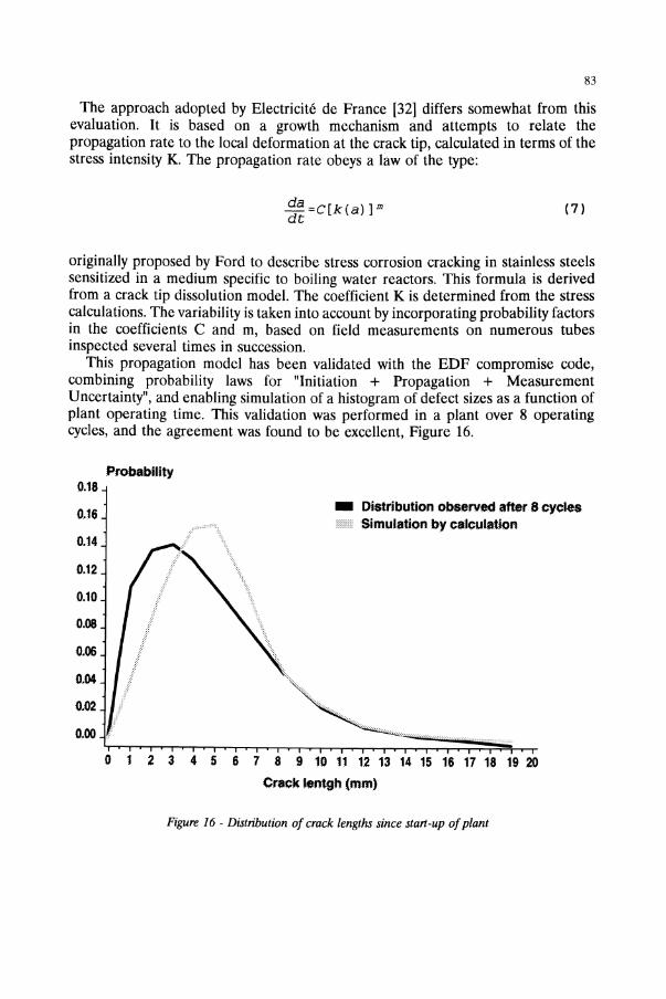
When associated with an evaluation of the hoop stress, this model makes itpossible to predict the variation of the crack distribution from one cycle to another,as a function of the crack length [31], Figure 15.
II
I
0,4-1-.. . I - -l~-1---1---
03 --- -f---, :.~ --- - _I 1_- -- -- _ __
!" 1([\,: 1J-1---+--+--I-'_-I---J-_.1~ ~. j/ "'~. Ii!~ 0,1 \iJ:.'''-: \ '.
t'.N'·,:-.:I I ;:,. '"
0,0 1 2 3 4 5 6 6 9 10 11 12 13 14 15
Crack size (mm)
I ._... 1989 RESULTS _. - 1990 CALCULATED -- 1990 RESULTS
Figure 15 - Calculated distribution of cracks for 1990 from 1989 data (310°C) and comparison with1990 inspection results.
83
The approach adopted by Electricite de France [32] differs somewhat from thisevaluation. It is based on a growth mechanism and attempts to relate thepropagation rate to the local deformation at the crack tip, calculated in terms of thestress intensity K. The propagation rate obeys a law of the type:
da =C[k(a)] mdt
(7)
_ Distribution observed etterS cycJesIf Simulation by calculation
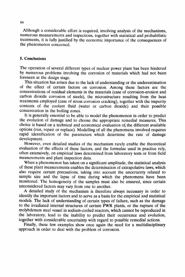
originally proposed by Ford to describe stress corrosion cracking in stainless steelssensitized in a medium specific to boiling water reactors. This formula is derivedfrom a crack tip dissolution model. The coefficient K is determined from the stresscalculations. The variability is taken into account by incorporating probability factorsin the coefficients C and m, based on field measurements on numerous tubesinspected several times in succession.This propagation model has been validated with the EDF compromise code,
combining probability laws for "Initiation + Propagation + MeasurementUncertainty", and enabling simulation of a histogram of defect sizes as a function ofplant operating time. This validation was performed in a plant over 8 operatingcycles, and the agreement was found to be excellent, Figure 16.
Probability0.18
0.16
0.14
0.12
0.10
0.08
0.06
0.04
0.02
0,(1() t,.,........--......,.....................-,.........-"....,......,-,---,-.-,=:::~~~!h--r-o 1 2 3 4 5 6 7 8 9 10 11 12 13 14 15 16 17 18 19 20
Crack 1entgh (mm)
Figure 16 - Distribution of crack lengths since start-up ofplant
84
Although a considerable effort is required, involving analysis of the mechanisms,numerous measurements and inspections, together with statistical and probabilistictreatments, it is fully justified by the economic importance of the consequences ofthe phenomenon concerned.
5. Conclusions
The operation of several different types of nuclear power plant has been hinderedby numerous problems involving the corrosion of materials which had not beenforeseen at the design stage.This situation has arisen due to the lack of understanding or the underestimation
of the effect of certain factors on corrosion. Among these factors are theconcentrations of residual elements in the materials (case of corrosion-erosion andcarbon dioxide corrosion of steels), the microstructure resulting from the heattreatments employed (case of stress corrosion cracking), together with the impuritycontents of the coolant fluid (water or carbon dioxide) and their possibleconcentration in the boiling zones.
It is generally essential to be able to model the phenomenon in order to predictthe evolution of damage and to choose the appropriate remedial measures. Thischoice is based on a technical and economical evaluation ot the different availableoptions (run, repair or replace). Modelling of all the phenomena involved requiresrapid identification of the parameters which determine the rate of damagedevelopment.However, even detailed studies of the mechanism rarely enable the theoretical
evaluation of the effects of these factors, and the formulae used in practice rely,often extensively, on empirical laws determined from laboratory tests or from fieldmeasurements and plant inspection data.When a phenomenon has taken on a significant amplitude, the statistical analysis
of these plant measurements enables the determination of extrapolative laws, whichalso require certain precautions, taking into account the uncertainty related tosample size and the lapse of time during which the phenomena have beenmonitored. The homogeneity of the samples must also be ensured, since certainunconsidered factors may vary from one to another.A detailed study of the mechanism is therefore always necessary in order to
identify the important factors and to serve as a basis for the empirical and statisticalmodels. The lack of understanding of certain types of failure, such as the damageto the irradiated internal structures of certain PWR plants, or the rupture of themolybdenum steel vessel in sodium-cooled reactors, which cannot be reproduced inthe laboratory, lead to the inability to predict their occurrence and evolution,together with considerable uncertainty with regard to possible remedial actions.Finally, these few examples show once again the need for a multidisciplinary
approach in order to deal with the problem of corrosion.

85
6. Acknowledgements
The author expresses his gratitude to D. Noel and P. Pitner (EDF) for discussionsand help on this paper.
References
1. Ph. Berge, E de Kdroulas, "The Present Situation regarding Environmental Degradationof Components in Pressurized Water Reactors", Paper presented at the 4th InternationalSymposium on Environmental Degradation in Nuclear Power Systems, Jekyll Island, USA,6-10 August, 1989.
2. RW. Staehle, "Combining Design and Corrosion for Predicting Life", Paper presentedat the Nace Symposium on Life Prediction of Corrodible Structure, Kavai, Hawaii, 5-8November, 1991.
3. Ph. Berge, H. Hennaut, M. Maurice, M. Wanee, "Etude morphologique des OxydesFormes sur les Aciers Inoxydables dans l'Eau et la Vapeur aHaute Temperature", MemoiresScientifiques, Rev. Metallurgique, Vol. 62, No.3, 1965.
4. J. Garaud, "La Corrosion des Aciers au Carbone par Ie Gaz Carbonique", Report GDLD551/5769, 1975, Electricite de France.
5. H.G. Heitmann, W. Kastner, "Erosion-Corrosion in Water Steam Cycles Causes andCounter Measures", Paper presented at Specialist Meeting on Corrosion-Erosion, Electricitede France, Les Renardieres, France, May, 1982.
6. GJ. Bignold, K. Garbett, R. Garnsey, I.S. Woolsey, "Erosion-Corrosion in NuclearSteam Generators", Paper presented at British Nuclear Engineering Society Conference,Boumemouth, United-Kingdom, 14-17 October, 1980.
7. Ph. Berge, J. Ducreux, P. Saint-Paul, "Effect of Chemistry on CorrosionErosion ofSteels in Water and Wet Steam", Paper presented at British Nuclear Engineering SocietyConference, Boumemouth, United-Kingdom, 14-17 October, 1980.
8. M. Bouchacourt, A. Lenormand, EN. Remy, "Corrosion-Erosion dans les CircuitsSecondaires - La maitrise du dommage", Paper presented at the SFEN InternationalSymposium, Fontevraud II, France, 10- 14 September, 1990.
9. W.M.M. Huijbregts, "The Influence of Chemical Composition of Carbon Steel onErosion-Corrosion in Wet Steam", Paper presented at Specialist Meering on CorrosionErosion, Electricite de France, Les Renardieres, France, May, 1982.
10. J. Ducreux, "Etude exp6rimentale de I'Influence de la Composition Chimique des Acierssur leur Resistance A I'Erosion-Corrosion", Paper presented at Specialist Meeting on
86
Corrosion-Erosion, Electricite de France, Les Renardieres, France, May, 1982.
11. M.W.E. Coney, H.S. Oates, SJ. Wilkin, "Thermal Hydraulic Effects on Mass TransferBehaviour and on Erosion-Corrosion Metal Loss Rates", Paper presented at SpecialistMeeting on Corrosion-Erosion, Electricite de France, Les Renardieres, France, May, 1982.
12. G.l. Bignold, K. Garbett, I.S. Woolsey, "Mechanistic Aspects of the TemperatureDependance of Erosion-Corrosion", Paper presented at Specialist Meeting on CorrosionErosion, Electricite de France, Les Renardieres, France, May, 1982.
13. R Boudot, "Methode d'Evaluation de la Sensibilite A la Corrosion Sous Contrainte enMilieu Primaire REP de Pieces en Alliages aBase de Nickel", Report HT40INEQ/1454.D,1992, Departement Etudes des Materiaux, DER, Electricite de France.
14. F.P. Ford, "Mechanisms of Environmental Cracking in Systems Peculiar to the PowerGeneration Industry", Report NP-2589, September, 1992, EPRI.
15. RW. Staehle, "Stress Corrosion Cracking of the Fe-Cr-Ni Alloy System", in "TheTheory of Stress Corrosion Cracking in Alloys", 1.e. Scully (Ed), NATO, Bruxelles, Belgium,1971,223.
16. C.H. Shen, P.G. Shewmon, "A Mechanism For Hydrogen-Induced Intergranular StressCorrosion Cracking in Alloy 600", Met, Trans., Vol 21A, 1990, 1261.
17. Y. Shen, P.G. Shewmon, "Intergranular Stress Corrosion Cracking of Alloy 600 and x750 in High Temperature Water", Met, Trans., Vol 22A, 1991, 1857.
18. P. Scott, M. Ie Calvar, "Some Possible Mechanisms of Intergranular Cracking of Alloy600 in PWR Primary Water", Paper presented at EPRI Airlie Workshop, Warrenton, VA,USA, 6-9 April, 1993.
19. G.S. Was, "Deformation and Intergranular Cracking Behaviour of Ni-Cr-Fe Alloys atHigh Temperature", Paper presented at EPRI Airlie Workshop, Warrenton, VA, USA, 6-9April, 1993.
20. M.M. Hall, "Thermally Activated Low Temperature Creep and Primary Water StressCorrosion Cracking of Ni-Cr-Fe Alloys", Paper presented at EPRI Airlie Workshop,Warrenton, VA, USA, 6-9 April, 1993.
21. T. Magnin, "A Unified Model for Trans and Intergranular Stress Corrosion Crackingin FCC Ductile Alloys",In: "Corrosion-Deformation Interactions", T. Magnin and 1.M. GrasEds., Les Editions de Physique, Fontainebleau, France, 5-7 October, 1992, 1993,27.
22. 1.M. Boursier, O. de Bouvier, J.M. Gras, D. Noel, R Rios, F. Vaillant, "SCC of Alloy600 in High Temperature Water: A Study of Mechanisms", In: "Corrosion-DeformationInteractions", T. Magnin and 1.M. Gras (Eds.), Les Editions de Physique, Fontainebleau,

87
France, 5-7 October, 1992, 1993, 117.
23. O. Cayla, P. Combrade, M. Foucault, A Gelpi, G. Slama, D. Vanqon, "About The Roleof Surface Films on Alloy 600 Corrosion in High Temperature Deaerated Environments",Paper presented at the 3rd International Symposium on Environmental Degradation ofMaterials in Nuclear Power Systems Water Reactors, Traverse City, USA, 30 August-3September, 1987.
24. C.A Zapffe, "Neumann Bands and the Planar-Pressure Theory of HydrogenEmbrittlement", J./.S./., Vol. 154, No.2, 1946, 123.
25. N.J. Petch, "The Lowering of Fracture-Stress Due to Surface Absoption", Phil. Mag.,Vol. 1, 1956, 331.
26. AR. Troiano, "The Role of Hydrogen and Other Interstitials in the MechanicalBehavior of Metals", Trans, ASM, 52, 1960, 54.
27. Ph. Berge, "Modelling Corrosion for Life Prediction of Nuclear Reactors Components",Paper presented at Nace Symposium on Life Prediction of Corrodible Structures,Cambridge, United-Kingdom, 23-26 September, 1991.
28. D. Gariga Majo, J.M. Gras, Y. Rouillon, F. Vaillant, J.c. Van Duysen, G. Zacharie,"Prediction of the Stress Corrosion Cracking Resistance of Alloy 600 in PurelPrimaryWater", Paper presented at the Nace Symposium on Life Prediction of CorrodibleStructures, Cambridge, United-Kingdom, 23-26 September, 1991.
29. P. Pitner, T. Riffard, "Traitement Statistique du Retour d'Experience sur I'Amorqagedes Fissures Longitudinales en Zone de Transition de Dudgeonnage (GV REP 900)",Report HP/ 16-90, 1990, Electricite de France.
30. I.A Gorman, R.W. Staehle, K.D. Strauropoulos, C.S. Welty, "Application of StatisticalDistributions to Characterizing and Predicting Corrosion in Tubing in Steam Generators ofPressurized Water Reactors", Paper presented at the Nace Symposium on Life Predictionof Corrodible Structures, Cambridge, United-Kingdom, 23-26 September, 1991.
31. P.M. Scott, "An Analysis of Primary Water Stress Corrosion Cracking in SteamGenerators", NENCSNI-UNIPEDE, Paper presented at Specialist Meeting on OperatingExperience with Steam Generators, BruxelIes, Belgium, 16-20 October, 1991.
32. B. Granger, "Tubes GV en Inconel 600 - Modelisation de la Corrosion Sous Tensiondans Ie Logiciel EPMGV", Report ENMEC.93.0025, 1993, Electricite de France.