
Modelling and Simulation for Micro Injection Molding …Modelling and Simulation for Micro Injection...
17
11 Modelling and Simulation for Micro Injection Molding Process Lei Xie 1 , Longjiang Shen 2,3 and Bingyan Jiang 3 1 Institute of Polymer Materials and Plastics Engineering, Clausthal University of Technology, 2 Institute of Mechanical Engineering, Clausthal University of Technology, 3 College of Mechanical and Electronic Engineering, Central South University,Changsha 1,2 Germany 3 P.R.China 1. Introduction 1.1 Micro injection molding process Since end of 60s’ last century, with the booming of the semi-conductive materials processing technologies related to IC (Integrated Circuits) industry, parts or components in micro-scale which is hard to see with naked eyes stepped into the attention of scientists. Thereafter, the various functional micro systems were rapidly widely used in different areas, such as watch and camera industry, printer ink jet, information storage, sensors and transducers, micro fluidic system, micro heat exchanger, micro reactor and so on (Madou M. J. 1997; Madou M. J. 2002). After impressive development, a new research scientific and engineering area was formed, named as Micro-Electronic-Mechanical systems (MEMs). Especially, in the last ten years, Micro optical electron system (MOEMS) and Bio- micro electron mechanical system (Bio-MEMS) played important roles in the Information Technology (IT) and Bio-Medical Engineering (BioM) fields (Yu L. Y.2002; Wilson K., Molnar P. & Hickman J. 2007; Spatz Joachim P. 2005; Pal, P. & Sato, K. 2009; Heckele M & Schomburg WK 2004). Fig. 1-1. Processing cycle of conventional injection molding process (Source: Veltkamp) www.intechopen.com
-
Upload
nguyenthien -
Category
Documents
-
view
254 -
download
6
Transcript of Modelling and Simulation for Micro Injection Molding …Modelling and Simulation for Micro Injection...
11
Modelling and Simulation for Micro Injection Molding Process
Lei Xie1, Longjiang Shen2,3 and Bingyan Jiang3 1Institute of Polymer Materials and Plastics Engineering,
Clausthal University of Technology, 2Institute of Mechanical Engineering, Clausthal University of Technology,
3College of Mechanical and Electronic Engineering, Central South University,Changsha 1,2Germany 3P.R.China
1. Introduction
1.1 Micro injection molding process
Since end of 60s’ last century, with the booming of the semi-conductive materials processing
technologies related to IC (Integrated Circuits) industry, parts or components in micro-scale
which is hard to see with naked eyes stepped into the attention of scientists. Thereafter, the
various functional micro systems were rapidly widely used in different areas, such as watch
and camera industry, printer ink jet, information storage, sensors and transducers, micro
fluidic system, micro heat exchanger, micro reactor and so on (Madou M. J. 1997; Madou M.
J. 2002). After impressive development, a new research scientific and engineering area was
formed, named as Micro-Electronic-Mechanical systems (MEMs). Especially, in the last ten
years, Micro optical electron system (MOEMS) and Bio- micro electron mechanical system
(Bio-MEMS) played important roles in the Information Technology (IT) and Bio-Medical
Engineering (BioM) fields (Yu L. Y.2002; Wilson K., Molnar P. & Hickman J. 2007; Spatz
Joachim P. 2005; Pal, P. & Sato, K. 2009; Heckele M & Schomburg WK 2004).
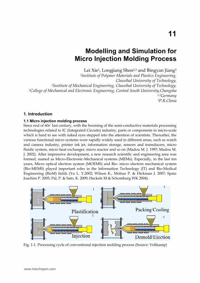
Fig. 1-1. Processing cycle of conventional injection molding process (Source: Veltkamp)
www.intechopen.com
Computational Fluid Dynamics Technologies and Applications
318
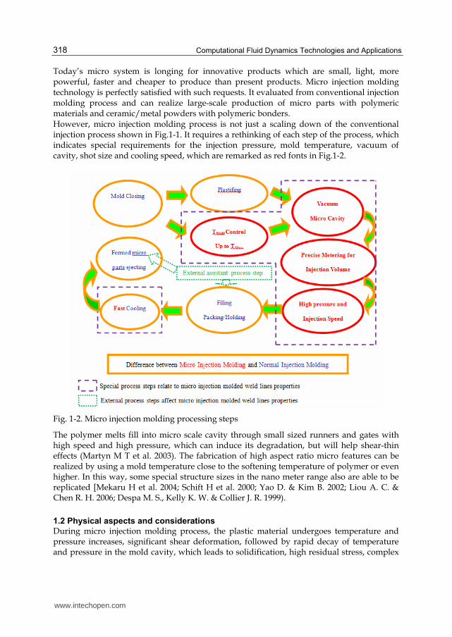
Today’s micro system is longing for innovative products which are small, light, more powerful, faster and cheaper to produce than present products. Micro injection molding technology is perfectly satisfied with such requests. It evaluated from conventional injection molding process and can realize large-scale production of micro parts with polymeric materials and ceramic/metal powders with polymeric bonders. However, micro injection molding process is not just a scaling down of the conventional injection process shown in Fig.1-1. It requires a rethinking of each step of the process, which indicates special requirements for the injection pressure, mold temperature, vacuum of cavity, shot size and cooling speed, which are remarked as red fonts in Fig.1-2.
Fig. 1-2. Micro injection molding processing steps
The polymer melts fill into micro scale cavity through small sized runners and gates with high speed and high pressure, which can induce its degradation, but will help shear-thin effects (Martyn M T et al. 2003). The fabrication of high aspect ratio micro features can be realized by using a mold temperature close to the softening temperature of polymer or even higher. In this way, some special structure sizes in the nano meter range also are able to be replicated [Mekaru H et al. 2004; Schift H et al. 2000; Yao D. & Kim B. 2002; Liou A. C. & Chen R. H. 2006; Despa M. S., Kelly K. W. & Collier J. R. 1999).
1.2 Physical aspects and considerations
During micro injection molding process, the plastic material undergoes temperature and pressure increases, significant shear deformation, followed by rapid decay of temperature and pressure in the mold cavity, which leads to solidification, high residual stress, complex
www.intechopen.com
Modelling and Simulation for Micro Injection Molding Process
319
molecular orientation, and other part properties that determine the molded part quality. The process design of micro injection molding involves the determination of a number of processing parameters, e.g., pressure (injection, holding, back and melt), temperature (coolant, nozzle, barrel, melt and mould), time (fill, holding, cooling and cycle), clamping force, injection speed, injection stroke, etc. In such process, the irregular geometry in micro scale and the complex thermo-mechanical history during the injection molding cycle, it is generally necessary to resort to numerical simulation methods to properly simulate the molding process and develop the capability of predicting the final configuration of the molded part, which is particularly important in precision injection molding operations. However, due to those special processing features of micro injection molding process (micro scale parts dimension, high pressure/shear rate, high mold temperature, and fast cooling speed), the flowing behavior and phase transfer of polymer melts perform different as well. Therefore, comparing with numerical simulation of conventional injection molding process, there are some new physical aspects associated with the scale-down of forming parts need to consider, which are: - Sliding of polymer frozen layer due to high shear stress near mold wall; - High heat transfer rate of polymer melts in micro cavity resulting from micro
mass/volume of materials; - Complex rheological behaviour of polymer melts flowing in micro geometry, especially
in sub-micro/nano dimensional cavities; - Dominating of sources force related to surface effect and neglecting of sources forces
contributed by viscous and interior because of the micro scale.
2. Software selection
Based on the criterion of technical performance, the selection of the CFD (computational fluid dynamics) software package for simulating micro injection molding process should consider the five aspects as following: - Friendly User-Interface(UI) contributes to the easy start-up for beginner; - Suitable mathematic models and efficient numerical solution method; - Flexible user define function for mathematic models and boundary conditions; - Convenient pre- and post- processing unit or interface; - High capability-price rate. Nevertheless, such software satisfied with all aspects is nearly possible, the users and customers need to make their decision depending on their stand and emphasis as for the application and project they are focusing on. The special commercial software for injection molding process are normally having human-based UI and powerful pre-/post- unit with smoothly operations, which make sure the beginner can drive the software in the short term, but such kind of software supplies less user defined functions limiting the software application in new technology development. In contrast, the general CFD packages open widely for user define ability in mathematic model, boundary condition, mesh elements type, numerical solution and multi-physical phenomena coupling, whereas they appear more complex and comprehensive operation interfaces which causes learning time-consuming.
2.1 Special commercial software for injection molding process
Since the first attempts to filling simulation of injection molding process, there have been numbers of commercial CAE software packages developed for injection molding process, in
www.intechopen.com
Computational Fluid Dynamics Technologies and Applications
320
which a couple of them have been maturely applied in industry and academics, such as MoldFlow®, Modex3D®, CADMOULD®, SIGAMA® etc. Though these software packages are originally developed for the process simulation of traditional injection molding, the 3D module of them are often used in micro injection molding, especially for the macro injection molding components with micro features. On the other side, with the rapid development of micro injection molding technology, these traditional injection molding based software packages are trying to satisfy the requirements of micro injection molding process simulation by technology update and progress.
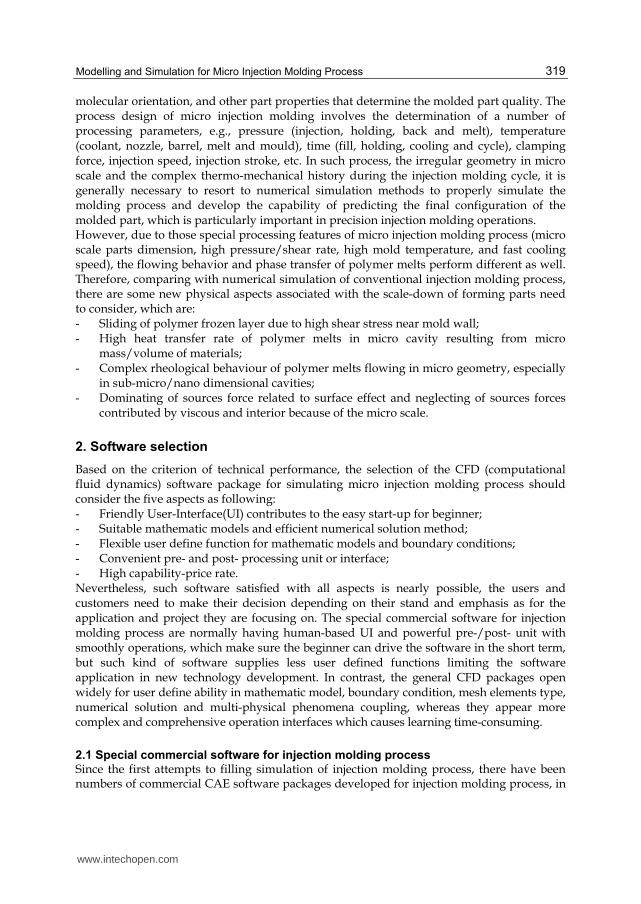
a) Multi-fiber connector micro injection molding simulation
b) 3D simulation of micro gear with 150µm diameter for weld line position prediction
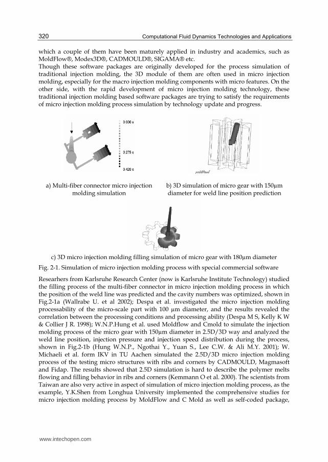
c) 3D micro injection molding filling simulation of micro gear with 180µm diameter
Fig. 2-1. Simulation of micro injection molding process with special commercial software
Researhers from Karlsruhe Research Center (now is Karlsruhe Institute Technology) studied the filling process of the multi-fiber connector in micro injection molding process in which the position of the weld line was predicted and the cavity numbers was optimized, shown in Fig.2-1a (Wallrabe U. et al 2002); Despa et al. investigated the micro injection molding processability of the micro-scale part with 100 µm diameter, and the results revealed the correlation between the processing conditions and processing ability (Despa M S, Kelly K W & Collier J R. 1998); W.N.P.Hung et al. used Moldflow and Cmold to simulate the injection molding process of the micro gear with 150µm diameter in 2.5D/3D way and analyzed the weld line position, injection pressure and injection speed distribution during the process, shown in Fig.2-1b (Hung W.N.P., Ngothai Y., Yuan S., Lee C.W. & Ali M.Y. 2001); W. Michaeli et al. form IKV in TU Aachen simulated the 2.5D/3D micro injection molding process of the testing micro structures with ribs and corners by CADMOULD, Magmasoft and Fidap. The results showed that 2.5D simulation is hard to describe the polymer melts flowing and filling behavior in ribs and corners (Kemmann O et al. 2000). The scientists from Taiwan are also very active in aspect of simulation of micro injection molding process, as the example, Y.K.Shen from Longhua University implemented the comprehensive studies for micro injection molding process by MoldFlow and C Mold as well as self-coded package,
www.intechopen.com
Modelling and Simulation for Micro Injection Molding Process
321
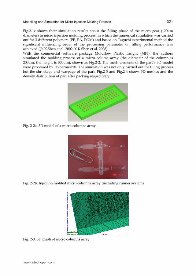
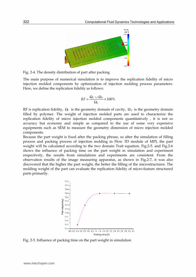
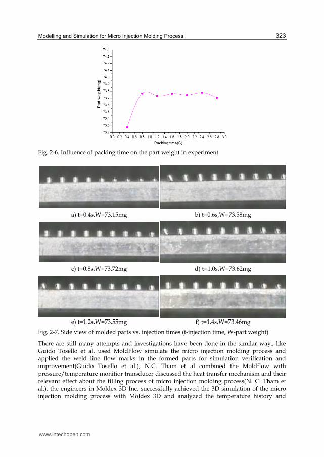
Fig.2-1c shows their simulation results about the filling phase of the micro gear (120µm diameter) in micro injection molding process, in which the numerical simulation was carried out for 3 different polymers (PP, PA, POM) and based on Taguchi experimental method the significant influencing order of the processing parameter on filling performance was achieved ((Y.K.Shen et al. 2002; Y.K.Shen et al. 2008). With the commercial software package Moldflow Plastic Insight (MPI), the authors simulated the molding process of a micro colums array (the diameter of the column is 200µm, the height is 300µm), shown as Fig.2-2. The mesh elements of the part’s 3D model were processed by Hypermesh®. The simulation was not only carried out for filling process but the shrinkage and warpage of the part. Fig.2-3 and Fig.2-4 shows 3D meshes and the density distribution of part after packing respectively.
Fig. 2-2a. 3D model of a micro columns array
Fig. 2-2b. Injection molded micro columns array (including runner system)
Fig. 2-3. 3D mesh of micro columns array
www.intechopen.com
Computational Fluid Dynamics Technologies and Applications
322
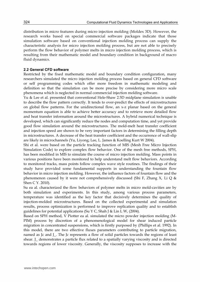
Fig. 2-4. The density distribution of part after packing
The main purpose of numerical simulation is to improve the replication fidelity of micro injection molded components by optimization of injection molding process parameters. Here, we define the replication fidelity as follows:
C P
C
RF 100%Ω ∪ Ω
= ×Ω
RF is replication fidelity, CΩ is the geometry domain of cavity, PΩ is the geometry domain
filled by polymer. The weight of injection molded parts are used to characterize the replication fidelity of micro injection molded components quantitatively , it is not so accuracy but economy and simple as compared to the use of some very expensive equipments such as SEM to measure the geometry dimension of micro injection molded components. Because the part weight is fixed after the packing phrase, so after the simulation of filling process and packing process of injection molding in Flow 3D module of MPI, the part weight will be calculated according to the two domain Trait equation. Fig.2-5. and Fig.2-6 shows the influence of packing time on the part weight in simulation and experiment respectively, the results from simulations and experiments are consistent. From the observation results of the image measuring apparatus, as shown in Fig.2-7, it was also discovered that the higher the part weight, the better the filling of the microstructures. The molding weight of the part can evaluate the replication fidelity of micro-feature structured parts primarily.
Fig. 2-5. Influence of packing time on the part weight in simulation
www.intechopen.com
Modelling and Simulation for Micro Injection Molding Process
323
Fig. 2-6. Influence of packing time on the part weight in experiment
a) t=0.4s,W=73.15mg b) t=0.6s,W=73.58mg
c) t=0.8s,W=73.72mg d) t=1.0s,W=73.62mg
e) t=1.2s,W=73.55mg f) t=1.4s,W=73.46mg
Fig. 2-7. Side view of molded parts vs. injection times (t-injection time, W-part weight)
There are still many attempts and investigations have been done in the similar way., like Guido Tosello et al. used MoldFlow simulate the micro injection molding process and applied the weld line flow marks in the formed parts for simulation verification and improvement(Guido Tosello et al.), N.C. Tham et al combined the Moldflow with pressure/temperature monitior transducer discussed the heat transfer mechanism and their relevant effect about the filling process of micro injection molding process(N. C. Tham et al.). the engineers in Moldex 3D Inc. successfully achieved the 3D simulation of the micro injection molding process with Moldex 3D and analyzed the temperature history and
www.intechopen.com
Computational Fluid Dynamics Technologies and Applications
324
distribution in micro features during micro injection molding (Moldex 3D). However, the research works based on special commercial software packages indicate that those simulation software based on conventional injection molding process can supply the characteristic analysis for micro injection molding process, but are not able to precisely perform the flow behavior of polymer melts in micro injection molding process, which is resulting from their mathematic model and boundary condition in background of macro fluid dynamics.
2.2 General CFD software
Restricted by the fixed mathematic model and boundary condition configuration, many researchers simulated the micro injection molding process based on general CFD software or self programming codes which offer more freedom in mathematic modeling and definition so that the simulation can be more precise by considering more micro scale phenomena which is neglected in normal commercial injection molding software. Yu & Lee et al. presented that conventional Hele-Shaw 2.5D midplane simulation is unable
to describe the flow pattern correctly. It tends to over-predict the effects of microstructures
on global flow patterns. For the unidirectional flow, an x-z planar based on the general
momentum equation is able to achieve better accuracy and to retrieve more detailed flow
and heat transfer information around the microstructures. A hybrid numerical technique is
developed, which can significantly reduce the nodes and computation time, and yet provide
good flow simulation around the microstructures. The mold-melt heat transfer coefficient
and injection speed are shown to be very important factors in determining the filling depth
in microstructures. A decrease of the heat transfer coefficient and the occurrence of wall-slip
are likely in microchannels (Yu, Liyong; Lee, L. James & Koelling Kurt W 2004).
Shi et al. were based on the particle tracking function of MIS (Mesh Free Micro Injection
Simulation Code) to explore complex flow behavior. One of the mesh free methods, SPH,
has been modified in MIS to simulate the course of micro injection molding. Mass points in
various positions have been monitored to help understand melt flow behaviors. According
to monitored tracks, mass points follow complex wave style routines. The findings of their
study have provided some fundamental supports in understanding the fountain flow
behavior in micro injection molding. However, the influence factors of fountain flow and the
phenomenon caused by it were not comprehensively discussed (Shi F, Zhang X, Li Q &
Shen C Y. 2010).
Su ea al. characterized the flow behaviors of polymer melts in micro mold-cavities are by
both simulation and experiments. In this study, among various process parameters,
temperature was identified as the key factor that decisively determines the quality of
injection-molded microstructures. Based on the collected experimental and simulation
results, process optimization is performed to improve replication quality and to establish
guidelines for potential applications (Su Y C, Shah J & Lin L W, (2004). Based on SPH method, V Piotter ea al. simulated the micro powder injection molding (M-PIM) process by discretion of a phenomenological model for shear induced particle migration in concentrated suspensions, which is firstly purposed by (Phillips et al. 1992). In this model, there are two effective fluxes parameters contributing to particle migration, named as Jc and J_. The Jc represents a flow of solid particles towards the regions of least shear. J_ demonstrates a particle flux related to a spatially varying viscosity and is directed towards regions of lower viscosity. Generally, the viscosity supposes to increase with the
www.intechopen.com
Modelling and Simulation for Micro Injection Molding Process
325
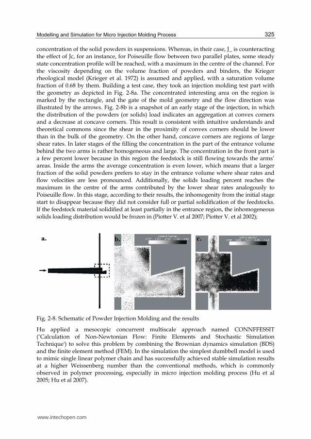
concentration of the solid powders in suspensions. Whereas, in their case, J_ is counteracting the effect of Jc, for an instance, for Poiseuille flow between two parallel plates, some steady state concentration profile will be reached, with a maximum in the centre of the channel. For the viscosity depending on the volume fraction of powders and binders, the Krieger rheological model (Krieger et al. 1972) is assumed and applied, with a saturation volume fraction of 0.68 by them. Building a test case, they took an injection molding test part with the geometry as depicted in Fig. 2-8a. The concentrated interesting area on the region is marked by the rectangle, and the gate of the mold geometry and the flow direction was illustrated by the arrows. Fig. 2-8b is a snapshot of an early stage of the injection, in which the distribution of the powders (or solids) load indicates an aggregation at convex corners and a decrease at concave corners. This result is consistent with intuitive understands and theoretical commons since the shear in the proximity of convex corners should be lower than in the bulk of the geometry. On the other hand, concave corners are regions of large shear rates. In later stages of the filling the concentration in the part of the entrance volume behind the two arms is rather homogeneous and large. The concentration in the front part is a few percent lower because in this region the feedstock is still flowing towards the arms’ areas. Inside the arms the average concentration is even lower, which means that a larger fraction of the solid powders prefers to stay in the entrance volume where shear rates and flow velocities are less pronounced. Additionally, the solids loading percent reaches the maximum in the centre of the arms contributed by the lower shear rates analogously to Poiseuille flow. In this stage, according to their results, the inhomogenity from the initial stage start to disappear because they did not consider full or partial solidification of the feedstocks. If the feedstock material solidified at least partially in the entrance region, the inhomogeneous solids loading distribution would be frozen in (Piotter V. et al 2007; Piotter V. et al 2002);
Fig. 2-8. Schematic of Powder Injection Molding and the results
Hu applied a mesocopic concurrent multiscale approach named CONNFFESSIT (‘Calculation of Non-Newtonian Flow: Finite Elements and Stochastic Simulation Technique') to solve this problem by combining the Brownian dynamics simulation (BDS) and the finite element method (FEM). In the simulation the simplest dumbbell model is used to mimic single linear polymer chain and has successfully achieved stable simulation results at a higher Weissenberg number than the conventional methods, which is commonly observed in polymer processing, especially in micro injection molding process (Hu et al 2005; Hu et al 2007).
www.intechopen.com
Computational Fluid Dynamics Technologies and Applications
326
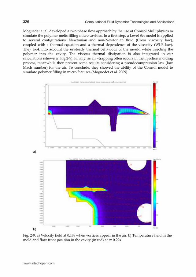
Moguedet et al. developed a two phase flow approach by the use of Comsol Multiphysics to simulate the polymer melts filling micro cavities. In a first step, a Level Set model is applied to several configurations: Newtonian and non-Newtonian fluid (Cross viscosity law), coupled with a thermal equation and a thermal dependence of the viscosity (WLF law). They took into account the unsteady thermal behaviour of the mould while injecting the polymer into the cavity. The viscous thermal dissipation is also integrated in our calculations (shown in Fig.2-9). Finally, as air –trapping often occurs in the injection molding process, meanwhile they present some results considering a pseudocompression law (low Mach number) for the air. To conclude, they showed the ability of the Comsol model to simulate polymer filling in micro features (Moguedet et al. 2009).
a)
b)
Fig. 2-9. a) Velocity field at 0.18s when vortices appear in the air; b) Temperature field in the mold and flow front position in the cavity (in red) at t= 0.29s
www.intechopen.com
Modelling and Simulation for Micro Injection Molding Process
327
The authors(Xie et al 2009) executed the simulation experiments for development of weld
line in micro injection molding process respectively with specific commercial software
(Mold Flow®) and general computational fluid dynamic (CFD) software (Comsol
®Multiphysics), and the real comparison experiments were also carried out. The results
show that during micro injection molding process, the specific commercial software for
normal injection molding process is not valid to describe the micro flow process, the shape
of flow front in micro cavity flowing which is important in weld line developing study and
the contact angle due to surface tension are not able to be simulated. In order to improve the
simulation results for micro weld line development, the general CFD software is applied
which is more flexible in user defining function. The results show better effects in describing
micro fluid flow behaviour. As a conclusion, as for weld line forming process, the numerical
simulation method can give a characteristic analysis results for processing parameters
optimizing in micro injection molding process, but for both kinds of software quantitative
analysis cannot be obtained unless the boundary condition and micro fluid mathematic
model are improved in the future.
According to the presented literatures on micro injection molding process simulation, it can
be found that with general CFD software, the numerical simulation can be more precise than
the case with special commercial software based on conventional injection molding process.
However, it cannot realize the quantitative analysis for the process even with self defined
CFD software, since there are still many phenomena and mechanism not clear yet for
microfluidics, especially in such comprehensively complex processing conditions. Therefore,
the improvement of modelling in physics and mathematics for microfluidics will be the key
issue to reach the better numerical simulation results.
3. Important issues in modelling and simulating of micro injection molding process
Physical and mathematic modelling for the process or phenomena supposed to be simulated
are always the most important issues and basement. The precise physical model with
appropriate assumption and simplification will lower the complication of the mathematic
description which is directly associated with the following solution efficiency. The next
sections will discuss the aspects should be emphasized in micro injection molding
simulation related to physical and mathematic points.
3.1 Physical model and assumption
The hele-shaw model (hieber & Shen 1982) is the typical physical model used in injection
molding process simulation that provides simplified governing equations for non-
isothermal, non-Newtonian and inelastic flows in a thin cavity, as shown in Fig.2-10. In
www.intechopen.com
Computational Fluid Dynamics Technologies and Applications
328
micro injection molding process, the model is also suitable when there is no special
phenomena need to describe, like fountain flow, jetting, particle tracing and filler/matrix
secretion etc. In hele-shaw model, normally the following assumption were purposed and
applied before mathematic modelling in the next step:
1. The thickness of the cavity is much smaller than the other dimensions, considered as
thin cavity;
2. Polymer melts are incompressible and viscous fluid without elastics, whose flowing
viscosity is shear dominated. Viscous force is much higher than inertia and
gravitational forces;
3. Velocity in thickness direction is zero and in thickness direction the pressure gradient is
zero as well;
4. The pressure in the flow front is zero and there is no fountain flow in the flow front;
5. There is no wall slides for frozen layer of polymers in the area near to mold walls;
6. The heat transfer between mold and polymer melts dominated by conductive way and
inner of polymer melts transfer the heat by the convection.
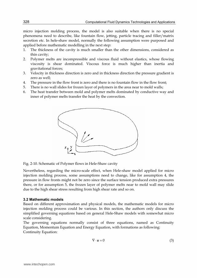
Fig. 2-10. Schematic of Polymer flows in Hele-Shaw cavity
Nevertheless, regarding the micro-scale effect, when Hele-shaw model applied for micro
injection molding process, some assumptions need to change, like for assumption 4, the
pressure in flow fronts might not be zero since the surface tension produced extra pressures
there, or for assumption 5, the frozen layer of polymer melts near to mold wall may slide
due to the high shear stress resulting from high shear rate and so on.
3.2 Mathematic models
Based on different approximation and physical models, the mathematic models for micro
injection molding process could be various. In this section, the authors only discuss the
simplified governing equations based on general Hele-Shaw models with somewhat micro
scale considering.
The governing equations normally consist of three equations, named as Continuity
Equation, Momentum Equation and Energy Equation, with formations as following:
Continuity Equation:
0∇ ⋅ =u (3)
www.intechopen.com
Modelling and Simulation for Micro Injection Molding Process
329
Momentum Equation:
D
pDt
2ρ ηγ ρ⋅
= −∇ + ∇ ⋅ + u
g (4)
Energy Equation:
( )pT
C T k Tt
2 :ρ ηγ γ⋅ ⋅∂
+ ⋅ ∇ = ∇ ⋅ ∇ + ∂ u (5)
where u , ρ , p ,η , γ⋅
, g , pC , T , k denote the velocity vector, density, pressure, non-
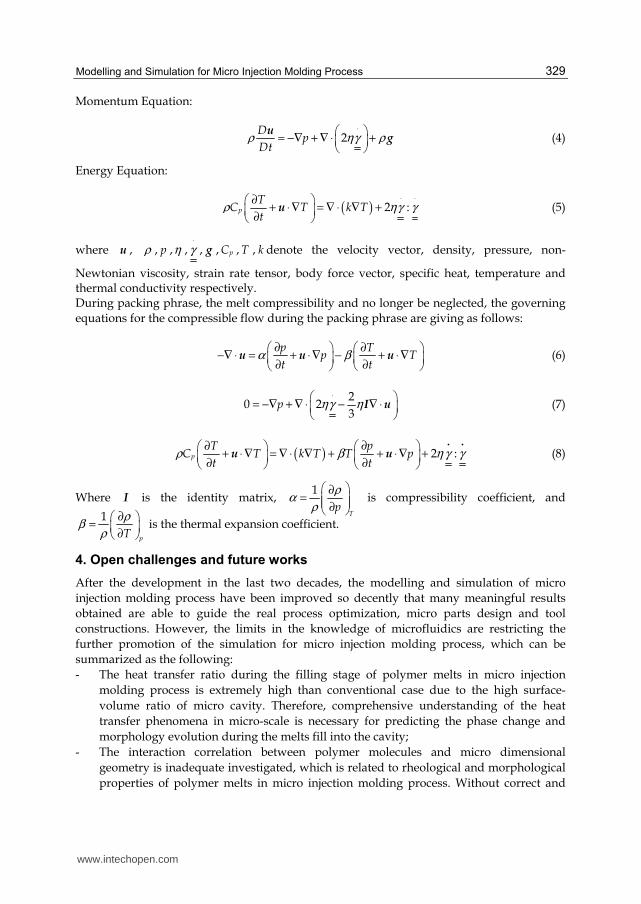
Newtonian viscosity, strain rate tensor, body force vector, specific heat, temperature and thermal conductivity respectively. During packing phrase, the melt compressibility and no longer be neglected, the governing
equations for the compressible flow during the packing phrase are giving as follows:
p T
p Tt t
α β∂ ∂
−∇ ⋅ = + ⋅ ∇ − + ⋅ ∇ ∂ ∂ u u u (6)
p2
0 23
ηγ η⋅
= −∇ + ∇ ⋅ − ∇ ⋅ I u (7)
( )p
pTC T k T T p
t t2 :ρ β η γ γ
∂∂ + ⋅ ∇ = ∇ ⋅ ∇ + + ⋅∇ +
∂ ∂
u u (8)
Where Ι is the identity matrix, T
p
1 ρα
ρ
∂= ∂ is compressibility coefficient, and
pT
1 ρβ
ρ
∂ =
∂ is the thermal expansion coefficient.
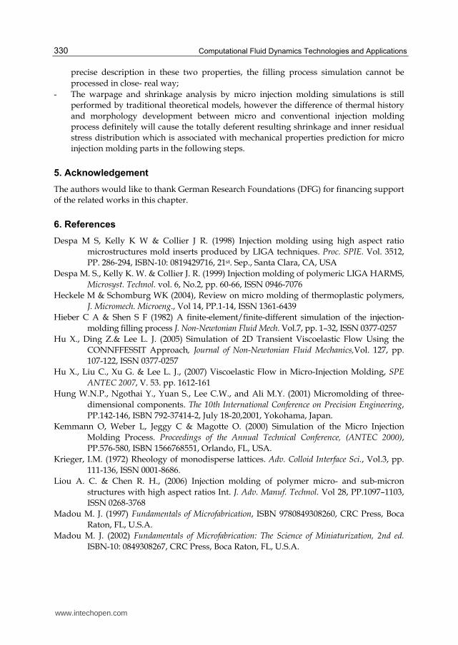
4. Open challenges and future works
After the development in the last two decades, the modelling and simulation of micro
injection molding process have been improved so decently that many meaningful results
obtained are able to guide the real process optimization, micro parts design and tool
constructions. However, the limits in the knowledge of microfluidics are restricting the
further promotion of the simulation for micro injection molding process, which can be
summarized as the following:
- The heat transfer ratio during the filling stage of polymer melts in micro injection
molding process is extremely high than conventional case due to the high surface-
volume ratio of micro cavity. Therefore, comprehensive understanding of the heat
transfer phenomena in micro-scale is necessary for predicting the phase change and
morphology evolution during the melts fill into the cavity;
- The interaction correlation between polymer molecules and micro dimensional
geometry is inadequate investigated, which is related to rheological and morphological
properties of polymer melts in micro injection molding process. Without correct and
www.intechopen.com
Computational Fluid Dynamics Technologies and Applications
330
precise description in these two properties, the filling process simulation cannot be
processed in close- real way;
- The warpage and shrinkage analysis by micro injection molding simulations is still
performed by traditional theoretical models, however the difference of thermal history
and morphology development between micro and conventional injection molding
process definitely will cause the totally deferent resulting shrinkage and inner residual
stress distribution which is associated with mechanical properties prediction for micro
injection molding parts in the following steps.
5. Acknowledgement
The authors would like to thank German Research Foundations (DFG) for financing support
of the related works in this chapter.
6. References
Despa M S, Kelly K W & Collier J R. (1998) Injection molding using high aspect ratio
microstructures mold inserts produced by LIGA techniques. Proc. SPIE. Vol. 3512,
PP. 286-294, ISBN-10: 0819429716, 21st. Sep., Santa Clara, CA, USA
Despa M. S., Kelly K. W. & Collier J. R. (1999) Injection molding of polymeric LIGA HARMS,
Microsyst. Technol. vol. 6, No.2, pp. 60-66, ISSN 0946-7076
Heckele M & Schomburg WK (2004), Review on micro molding of thermoplastic polymers,
J. Micromech. Microeng., Vol 14, PP.1-14, ISSN 1361-6439
Hieber C A & Shen S F (1982) A finite-element/finite-different simulation of the injection-
molding filling process J. Non-Newtonian Fluid Mech. Vol.7, pp. 1–32, ISSN 0377-0257
Hu X., Ding Z.& Lee L. J. (2005) Simulation of 2D Transient Viscoelastic Flow Using the
CONNFFESSIT Approach, Journal of Non-Newtonian Fluid Mechanics,Vol. 127, pp.
107-122, ISSN 0377-0257
Hu X., Liu C., Xu G. & Lee L. J., (2007) Viscoelastic Flow in Micro-Injection Molding, SPE
ANTEC 2007, V. 53. pp. 1612-161
Hung W.N.P., Ngothai Y., Yuan S., Lee C.W., and Ali M.Y. (2001) Micromolding of three-
dimensional components. The 10th International Conference on Precision Engineering,
PP.142-146, ISBN 792-37414-2, July 18-20,2001, Yokohama, Japan.
Kemmann O, Weber L, Jeggy C & Magotte O. (2000) Simulation of the Micro Injection
Molding Process. Proceedings of the Annual Technical Conference, (ANTEC 2000),
PP.576-580, ISBN 1566768551, Orlando, FL, USA.
Krieger, I.M. (1972) Rheology of monodisperse lattices. Adv. Colloid Interface Sci., Vol.3, pp.
111-136, ISSN 0001-8686.
Liou A. C. & Chen R. H., (2006) Injection molding of polymer micro- and sub-micron
structures with high aspect ratios Int. J. Adv. Manuf. Technol. Vol 28, PP.1097–1103,
ISSN 0268-3768
Madou M. J. (1997) Fundamentals of Microfabrication, ISBN 9780849308260, CRC Press, Boca
Raton, FL, U.S.A.
Madou M. J. (2002) Fundamentals of Microfabrication: The Science of Miniaturization, 2nd ed.
ISBN-10: 0849308267, CRC Press, Boca Raton, FL, U.S.A.
www.intechopen.com
Modelling and Simulation for Micro Injection Molding Process
331
Martyn M T, Whiteside B, Coates P D, Allan P S, Greenway G & Hornsby P, (2003)
Micromoulding: consideration of processing effects on medical materials, SPE
ANTEC Proc. pp. 2582-2586
Mekaru H, Yamada T, Yan S & Hattori T., (2004) Microfabrication by hot embossing and
injection molding at LASTI, Microsyst. Technol. Vol10, PP.682–688, ISSN 0946-7076
Moguedet M., Le Goff R., Namy P. & Béreaux Y. (2009) Level Set Method for Fully Thermal-
Mechanical Coupled Simulations of Filling in Injection and Micro-Injection
molding Process, Proceedings of the COMSOL Conference 2009, Milan, Italy
Pal, P. & Sato, K. (2009) Silicon microfluidic channels and microstructures in single
photolithography step, Design, Test, Integration & Packaging of MEMS/MOEMS '09.
Symposium, PP.419-423, ISBN 978-2-35500-009-6, 2009,1-4, April, Rome, Italy
Phillips, R.J.; Armstrong, R.C.; Brown, R.A.; Graham, R.L.; Abbott, J.R. (1992) A constitutive
equation for concentrated suspensions that accounts for shear induced particle
migration. Phys. Fluids, A 4, pp. 30-40, ISSN 1070-6631.
Piotter V. et al. (2002) Performance and simulation of thermoplastic micro injection molding,
Microsyst. Technol. vol. 8, No.6, pp. 387-390, ISSN 0946-7076
Piotter V. et al., (2007) Micro injection moulding: special variants and simulation. MiNaT :Internat.Fachmesse und Kongress für Feinwerktechnik, Ultrapräzision, Micro- und Nano-
Technologien, Stuttgart, 11.-15.Juni 2007
Schift H, David C, Gabriel M, Gobrecht J, Heyderman L J, Kaiser W, Koeppel S & Scandella
L., (2000) Nanoreplication in polymers using hot embossing and injection molding,
Microelectron. Eng. Vol 53, PP.171–174, ISSN 0167-9317
Shen Y. K., Chih-Yuan Chang, Yu-Sheng Shen, Sung-Chih Hsu & Ming-Wei Wu, (2008) Analysis
for microstructure of microlens arrays on micro-injection molding by numerical
simulation, Int. Comm. Heat Mass Transfer,Vol 35, No.6, PP. 723-727, ISSN 0735-1933
Shen Y.K., Yeh S.L. & Chen S.H. (2002) Three-dimensional non-Newtonian Computations of
Micro-Injection Molding with the Finite Element Method. Int. Comm. Heat Mass
Transfer,Vol 29, No.5, PP. 643-652, ISSN 0735-1933
Shi F, Zhang X, Li Q & Shen C Y. (2010) Particle tracking in micro-injection molding simulated
MIS, Computer Engineering and Technology (ICCET), 2010 2nd International Conference,
PP.313-317, Vol.5, ISBN: 978-1-4244-6347-3, 16-18 April 2010, Chendu, China
Spatz Joachim P. (2005) Bio-MEMS: Building up micromuscles, Nature Materials, Vol 4, PP
115-116, ISSN 1476-1122
Su Y C, Shah J & Lin L W, (2004) Implementation and analysis of polymeric microstructure
replication by micro injection molding, J. Micromech. Microeng., Vol 14, PP.415-4,
ISSN 1361-6439
Wallrabe U. et al (2002) Micromolded easy-assembly multi fiber connector: RibCon, c
Wilson K., Molnar P. & Hickman J. (2007) Integration of functional myotubes with a Bio- MEMS
device for non-invasive interrogation, Lab on a Chip, Vol 7, PP 920-922, ISSN 1473-0197
Xie L, Ziegmann G & Jiang B Y, (2009) Numerical simulation method for weld line
development in micro injection molding process, Journal of Central South University
of Technology, Vol. 16, Nr. 5,pp. 774-780, ISSN 1005-9784
Yao D. & Kim B. (2002) Injection molding high aspect ratio microfeatures, J. Injection Molding
Technol. Vol 6, PP.11–17, ISSN 1533-905X
www.intechopen.com

Computational Fluid Dynamics Technologies and Applications
332
Yu L. Y. (2004) Experimental and numerical analysis of injection molding with micro features,
PhD Dissertation, Ohio State University, Ohio, U.S.A.
Yu, Liyong, Lee, L. James & Koelling, Kurt W.(2004) Flow and heat transfer simulation of
injection molding with microstructures, Polymer Engineering and Science, Vol 44,
PP.1866–1876, ISSN1548-2634
www.intechopen.com
Computational Fluid Dynamics Technologies and ApplicationsEdited by Prof. Igor Minin
ISBN 978-953-307-169-5Hard cover, 396 pagesPublisher InTechPublished online 05, July, 2011Published in print edition July, 2011
InTech EuropeUniversity Campus STeP Ri Slavka Krautzeka 83/A 51000 Rijeka, Croatia Phone: +385 (51) 770 447 Fax: +385 (51) 686 166www.intechopen.com
InTech ChinaUnit 405, Office Block, Hotel Equatorial Shanghai No.65, Yan An Road (West), Shanghai, 200040, China
Phone: +86-21-62489820 Fax: +86-21-62489821
This book is planned to publish with an objective to provide a state-of-art reference book in the area ofcomputational fluid dynamics for CFD engineers, scientists, applied physicists and post-graduate students.Also the aim of the book is the continuous and timely dissemination of new and innovative CFD research anddevelopments. This reference book is a collection of 14 chapters characterized in 4 parts: modern principles ofCFD, CFD in physics, industrial and in castle. This book provides a comprehensive overview of thecomputational experiment technology, numerical simulation of the hydrodynamics and heat transfer processesin a two dimensional gas, application of lattice Boltzmann method in heat transfer and fluid flow, etc. Severalinteresting applications area are also discusses in the book like underwater vehicle propeller, the flow behaviorin gas-cooled nuclear reactors, simulation odour dispersion around windbreaks and so on.
How to referenceIn order to correctly reference this scholarly work, feel free to copy and paste the following:
Lei Xie, Longjiang Shen and Bingyan Jiang (2011). Modelling and Simulation for Micro Injection MoldingProcess, Computational Fluid Dynamics Technologies and Applications, Prof. Igor Minin (Ed.), ISBN: 978-953-307-169-5, InTech, Available from: http://www.intechopen.com/books/computational-fluid-dynamics-technologies-and-applications/modelling-and-simulation-for-micro-injection-molding-process