
Modelling
63
What is geometric modeling? • Collection of methods used to define the shape and other geometric characteristics of an object. • To construct a precise mathematical description of the shape of a real object or to simulate some process. • Embraces area – computational geometry
-
Upload
kannan-kandappan -
Category
Documents
-
view
1 -
download
0
description
Finite element analysis - Modelling types
Transcript of Modelling
What is geometric modeling?
• Collection of methods used to define the shape and other geometric characteristics of an object.
• To construct a precise mathematical description of the shape of a real object or to simulate some process.
• Embraces area – computational geometry

What is geometric modeling?
• special case of mathematical modeling• the visual features are important.• geometric model - physical object.• non-geometric model – physical process e.g economic
Geometric data
• To make pictures/ design new things need a computer representation of objects.
• Need to represent– Shape– Appearance (color, shininess etc)– Material properties (density, stiffness etc)

• Geometric data representation- Compute a mathematical approximation of the physical
shape of an object
• Algorithms for manipulating geometry– Manipulate the variables defining the shape until we meet
the objective.
• Geometry creation– Interactive.– Automatic creation.
geometric modeling

Application
• Computer Aided Design/ engineering (CAD/CAE)
• Entertainment– Special effects– Animation– games
• Scientific visualization• Education, information, advertising
CAD/CAE
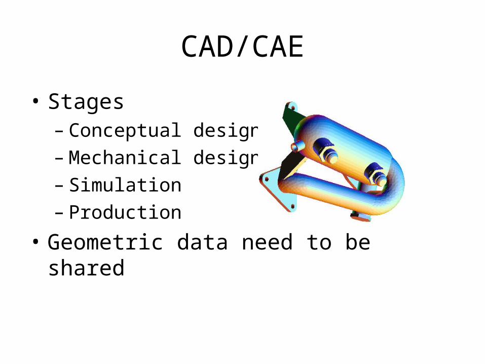
• Stages– Conceptual design– Mechanical design– Simulation– Production
• Geometric data need to be shared
CAD/CAE
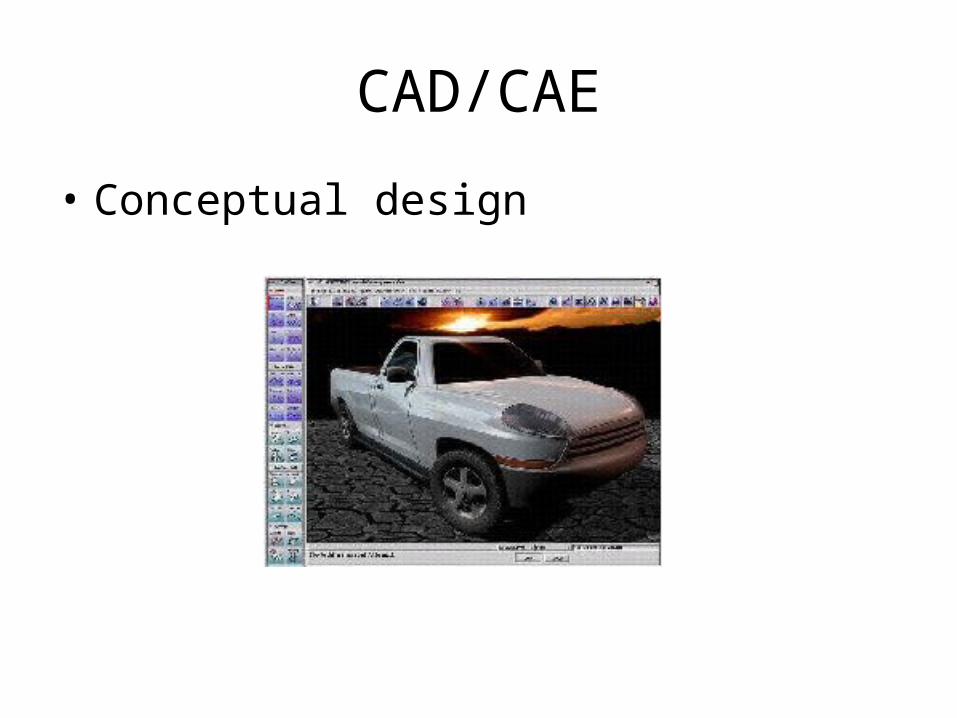
• Conceptual design
CAD/CAE
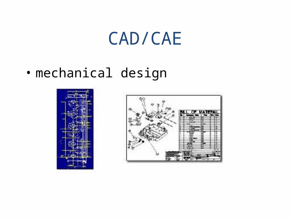
• mechanical design
CAD/CAE
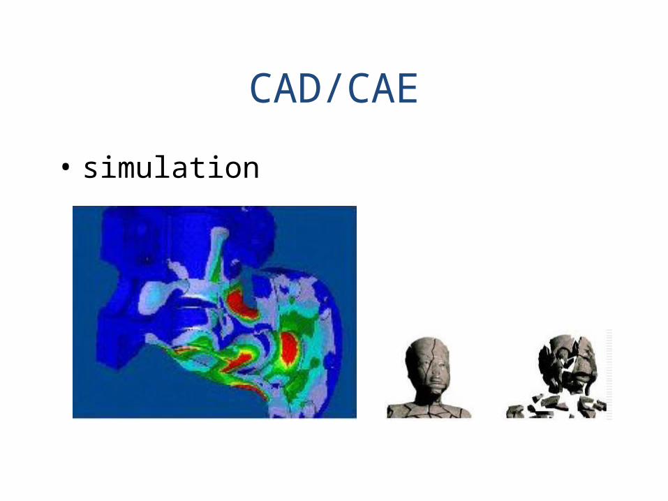
• simulation
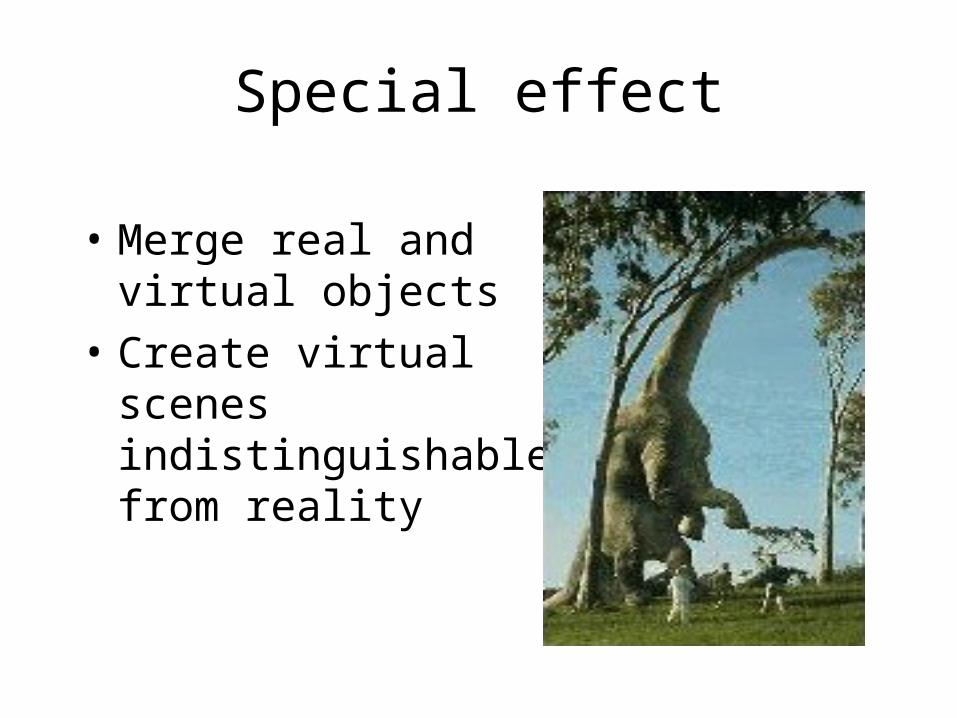
Special effect
• Merge real and virtual objects
• Create virtual scenes indistinguishable from reality

animation

games
• Adventure - interactive
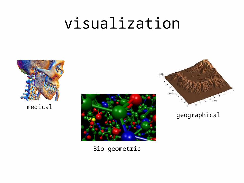
visualization
geographicalmedical
Bio-geometric
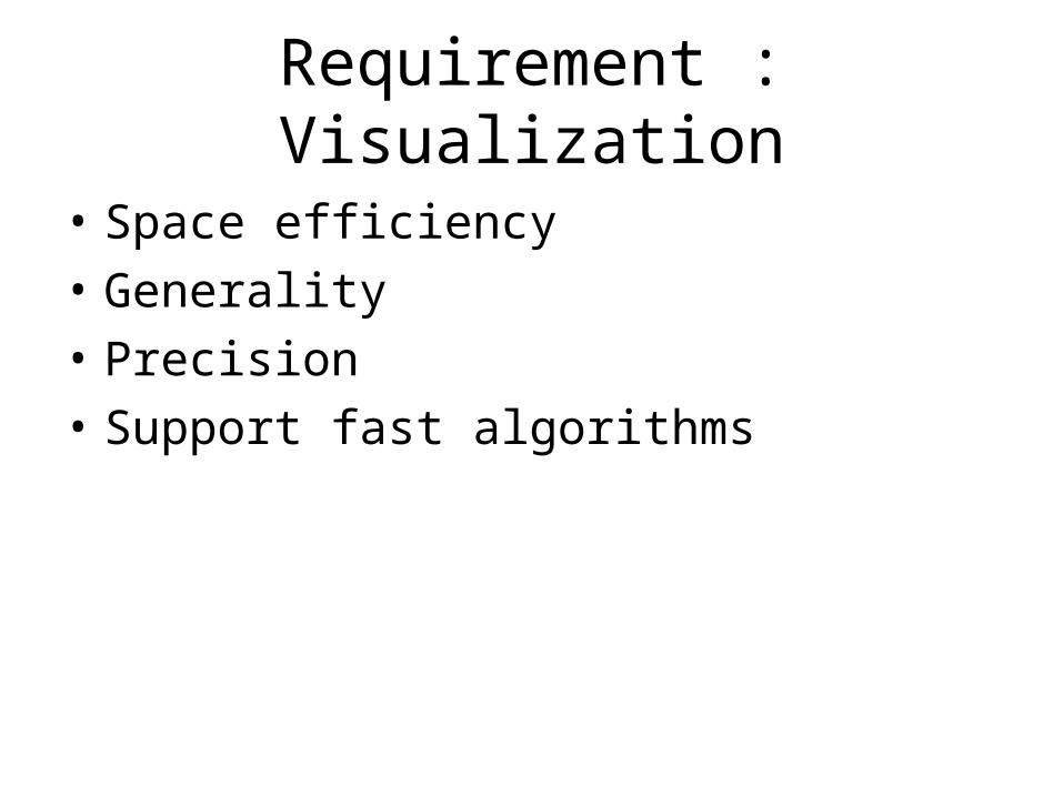
Requirement : Visualization
• Space efficiency• Generality• Precision• Support fast algorithms
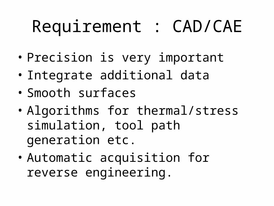
Requirement : CAD/CAE
• Precision is very important• Integrate additional data• Smooth surfaces• Algorithms for thermal/stress simulation, tool
path generation etc.• Automatic acquisition for reverse engineering.
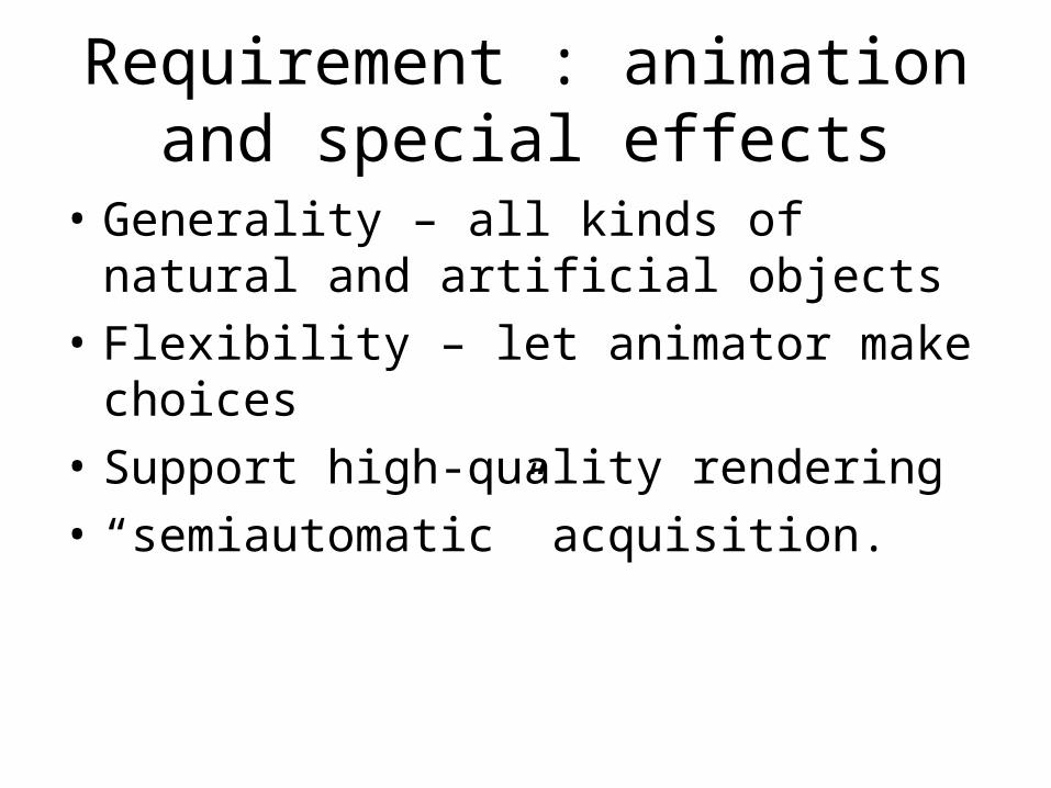
Requirement : animation and special effects
• Generality – all kinds of natural and artificial objects
• Flexibility – let animator make choices• Support high-quality rendering• “semiautomatic” acquisition.
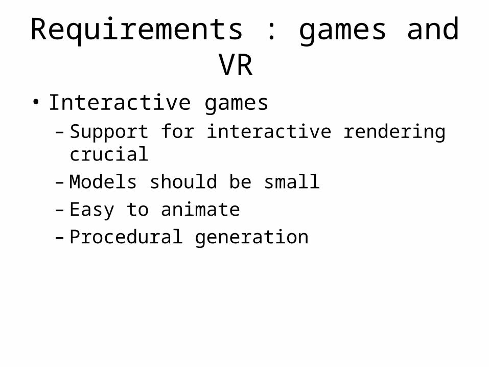
Requirements : games and VR
• Interactive games– Support for interactive rendering crucial– Models should be small– Easy to animate– Procedural generation
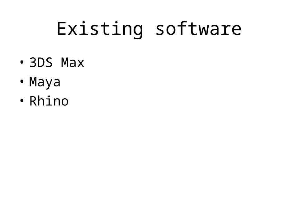
Existing software
• 3DS Max• Maya• Rhino
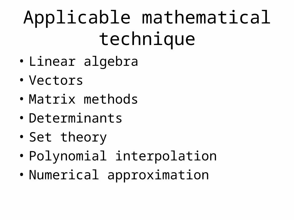
Applicable mathematical technique
• Linear algebra• Vectors• Matrix methods• Determinants• Set theory• Polynomial interpolation• Numerical approximation
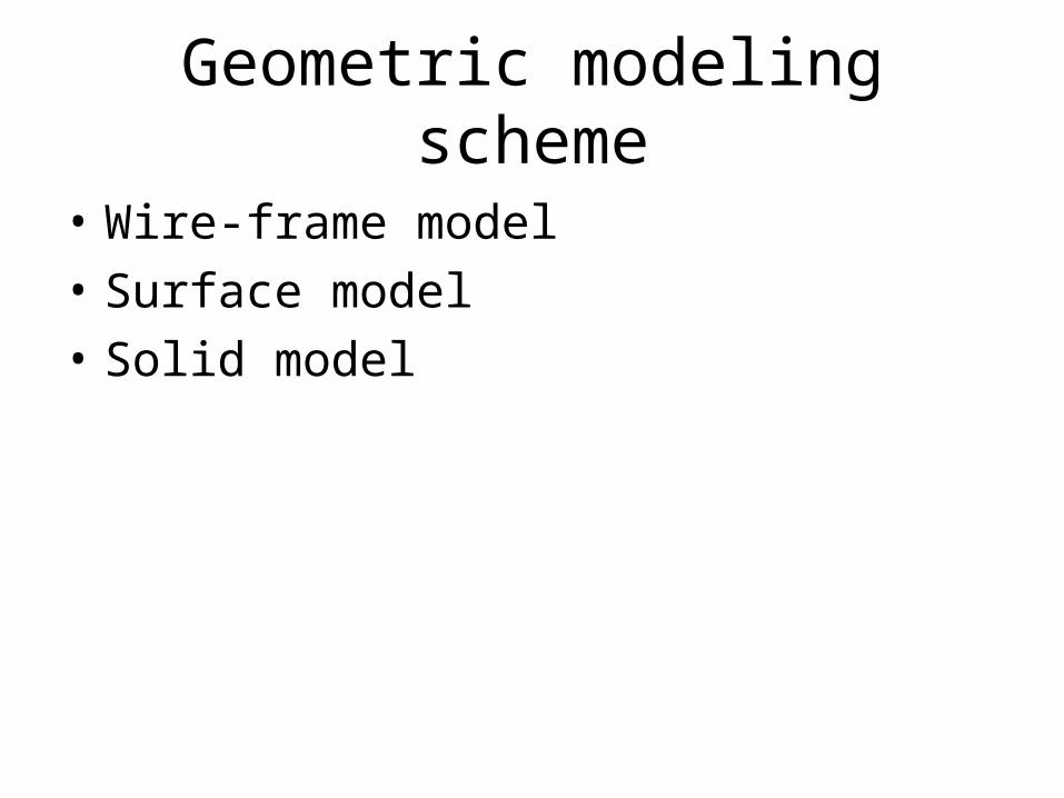
Geometric modeling scheme
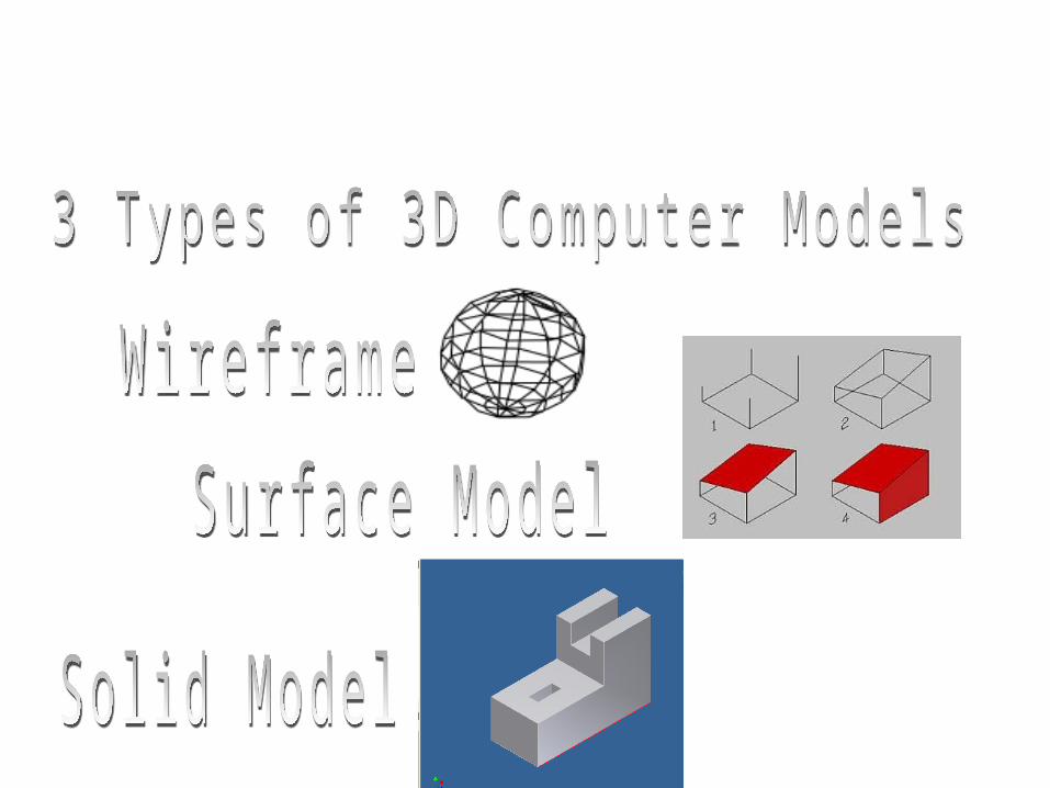
• Wire-frame model• Surface model• Solid model
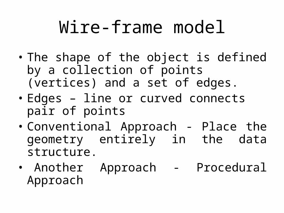
Wire-frame model
• The shape of the object is defined by a collection of points (vertices) and a set of edges.
• Edges – line or curved connects pair of points• Conventional Approach - Place the geometry
entirely in the data structure.• Another Approach - Procedural Approach

• Example : tetrahedron
Wire-frame model

Disadvantages of wire-frame
• Tend to be not realistic• Ambiguity
– complex model difficult to interpret.
What does this object look like?
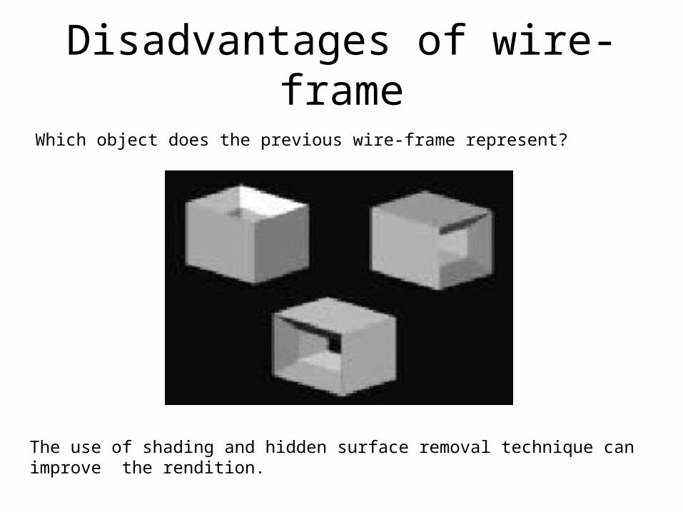
Disadvantages of wire-frameWhich object does the previous wire-frame represent?
The use of shading and hidden surface removal technique can improve the rendition.

• Does not allow for use of photo realistic rendering tools. *(some software capable of hidden line removal on limited basis).
• No ability to determine computationally information on mass properties (e.g volume, mass, moment etc) and line of intersect between two faces of intersecting models.
• No guarantee that the model definition is correct, complete or manufacturable.
Disadvantages of wire-frame

Advantages of wire-frame
• Easy to construct• Most economical in term of time and memory
requirement. • Used to model solid object.• Often used for previewing objects in an
interactive scenario.

Surface model
• An area bounded by an identifiable perimeter.
• In Computer Graphics, is an area within which every position is defined by mathematical method.
Surface model
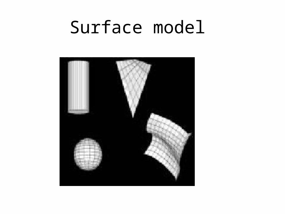
Surface may be:
– Planar
– Cylindrical/conic
– Sculptured or freeform in shape
Surface model
• To overcome ambiguity in wire-frame model
•used for the generation of visually
realistic images through techniques
such as
•rendering•hidden edge removal.
Surface model

•Does not represent internal features of
the model, no sense of volume.
•Models of limited value for volumetric and mass property analysis.
Surface model

Solid model
• Most complex• Complete representation• unambiguous description• Appropriate for the world of engineering
objects
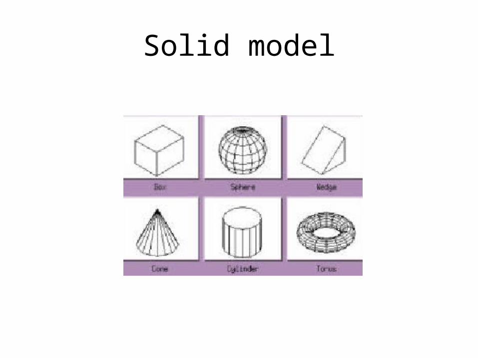
Solid model
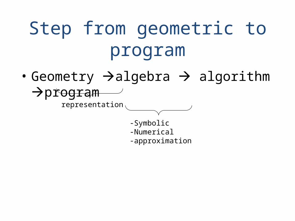
Step from geometric to program
• Geometry algebra algorithm program
representation
-Symbolic-Numerical-approximation

The development of 3D modelling software enables architects and design engineers to create realistic 3D models of their designs.
Previously they would have been built from clay, card or polystyrene blocks.
A 3D computer model is a virtual object which can be rotated on screen and viewed from any angle.
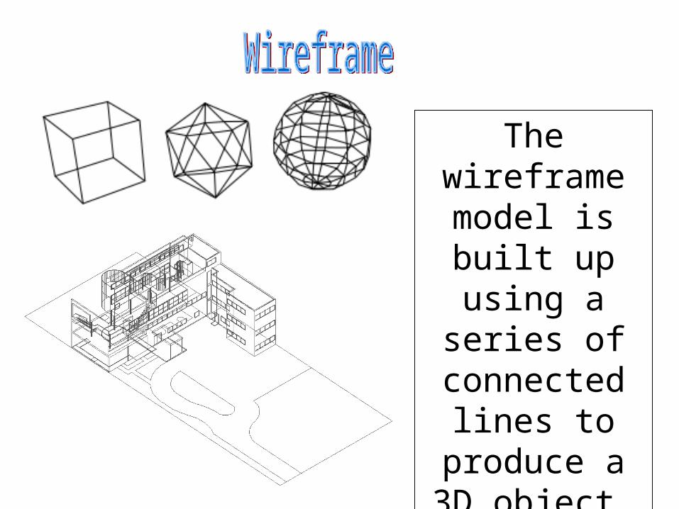
The wireframe model is built
up using a series of
connected lines to
produce a 3D object.
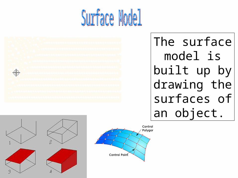
The surface model is built up by drawing the surfaces of
an object.
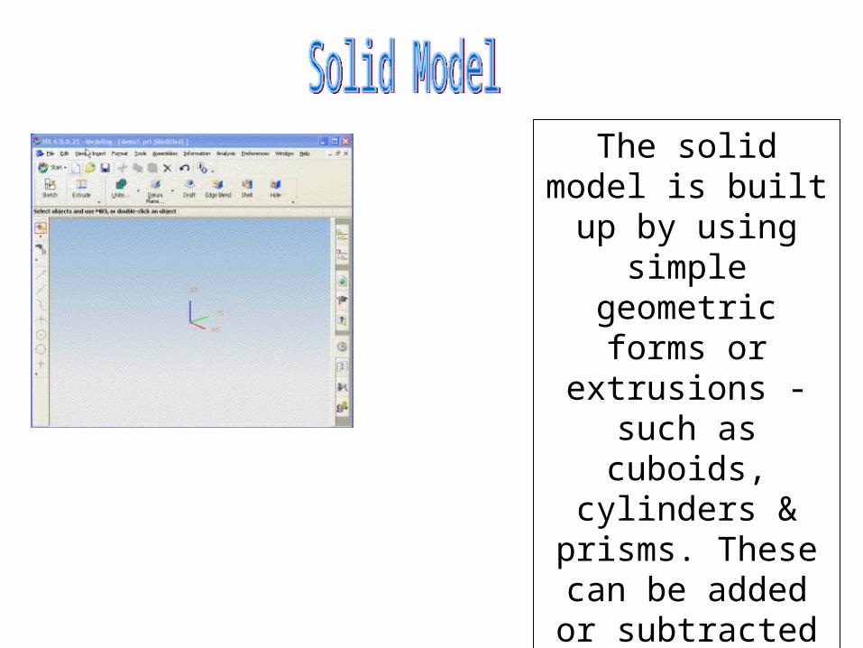
The solid model is built up by using simple geometric
forms or extrusions - such as cuboids, cylinders & prisms.
These can be added or
subtracted to produce complex
3D models.

Can be produced very quickly.
Can be modified very easily.
Easily add colour & surface texture.
Test structural designs before building eg bridges & skyscrapers.
Easily sent by email to remote locations throughout the world.
Less storage space required than a ‘real’ model.
Used to create realistic simulations.
Clients can explore virtual ‘walk through’ of 3D model designs.
Computer generated models are virtual and can lack the feel of a traditional model which can be picked up and handled.
Purchase cost of computers and software.
Training of staff in use of software.
Maintenance of IT systems & network servers.
SOLID MODELLING

Why solid modeling?
• Recall weakness of wireframe and surface modeling– Ambiguous geometric description– incomplete geometric description– lack topological information– Tedious modeling process– Awkward user interface

Solid model
• Solid modeling is based on complete, valid and unambiguous geometric representation of physical object.– Complete points in space can be classified.
(inside/ outside)– Valid vertices, edges, faces are connected
properly.– Unambiguous there can only be one
interpretation of object
Solid model
• Analysis automation and integration is possible only with solid models has properties such as weight, moment of inertia, mass.
• Solid model consist of geometric and topological data– Geometry shape, size, location of geometric
elements– Topology connectivity and associativity of geometric
elements non graphical, relational information

Solid model representation schemes
1. Constructive solid geometry (CSG)2. Boundary representation (B-rep) 3. Spatial enumeration4. Instantiation.
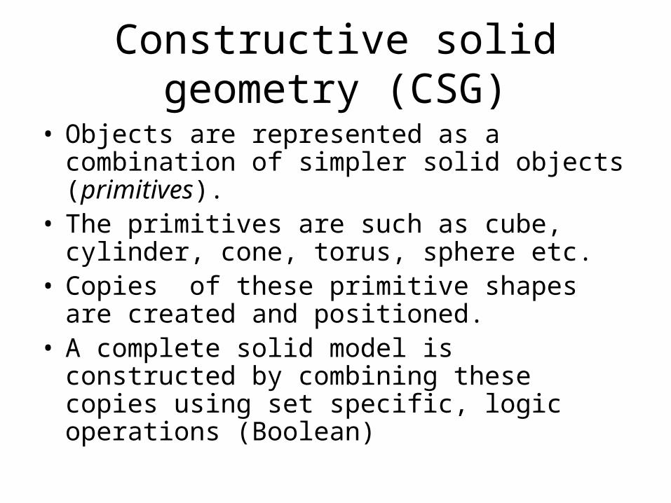
Constructive solid geometry (CSG)• Objects are represented as a combination of simpler
solid objects (primitives).• The primitives are such as cube, cylinder, cone,
torus, sphere etc. • Copies of these primitive shapes are created and
positioned.• A complete solid model is constructed by combining
these copies using set specific, logic operations (Boolean)

• Boolean operation– each primitive solid is assumed to be a set of
points, a boolean operation is performed on point sets and the result is a solid model.
– Boolean operation union, intersection and difference
– The relative location and orientation of the two primitives have to be defined before the boolean operation can be performed.
– Boolean operation can be applied to two solids other than the primitives.
Constructive solid geometry (CSG)

• Union– The sum of all points in each of two defined
sets. (logical “OR”)– Also referred to as Add, Combine, Join, Merge
Constructive solid geometry (CSG)- boolean operation
A BA B

• Difference– The points in a source set minus the points
common to a second set. (logical “NOT”)– Set must share common volume– Also referred to as subtraction, remove, cut
Constructive solid geometry (CSG)- boolean operation
A - BA B

• intersection– Those points common to each of two
defined sets (logical “AND”)– Set must share common volume– Also referred to as common, conjoin
Constructive solid geometry (CSG)- boolean operation
A BA B
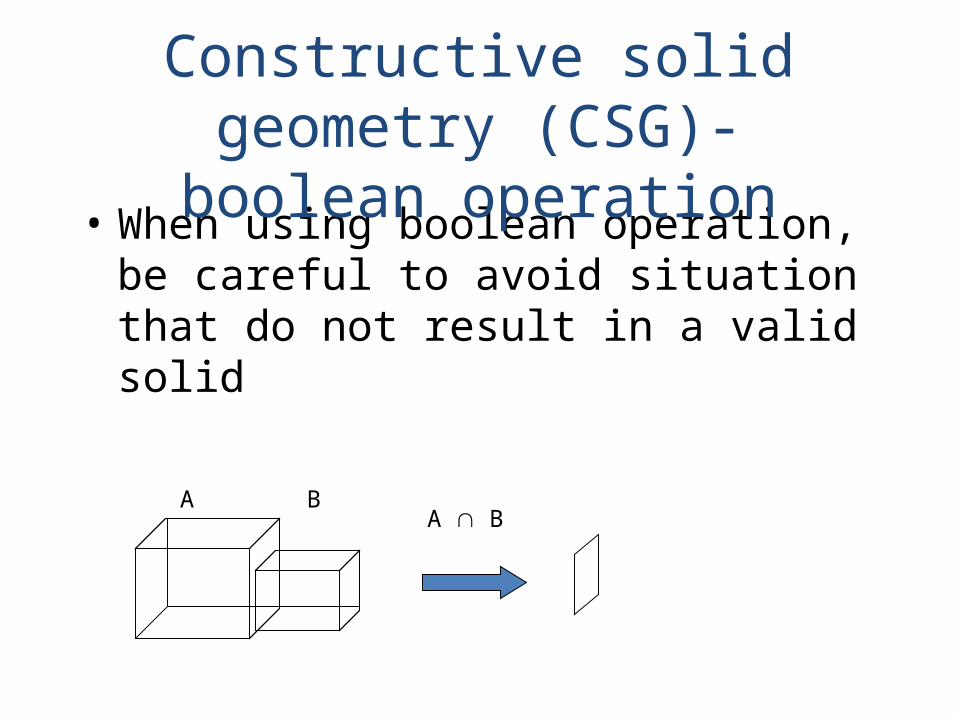
• When using boolean operation, be careful to avoid situation that do not result in a valid solid
Constructive solid geometry (CSG)- boolean operation
A BA B

• Boolean operation– Are intuitive to user– Are easy to use and understand– Provide for the rapid manipulation of large
amounts of data.• Because of this, many non-CSG systems also
use Boolean operations
Constructive solid geometry (CSG)- boolean operation
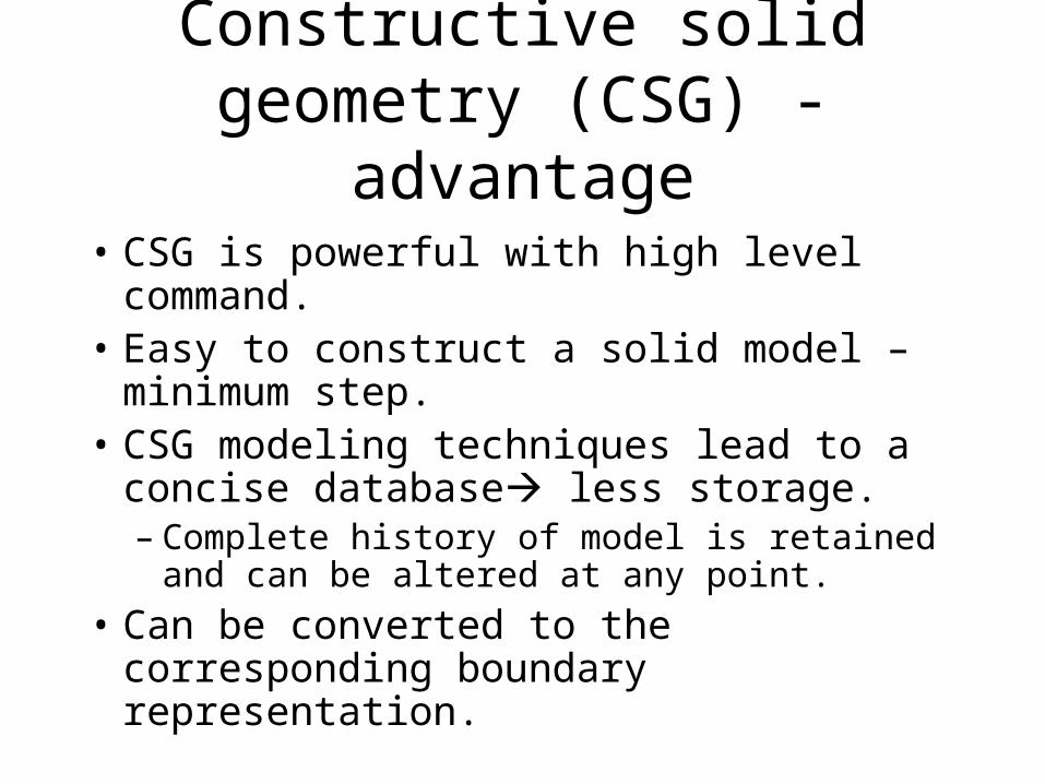
• CSG is powerful with high level command.• Easy to construct a solid model – minimum
step.• CSG modeling techniques lead to a concise
database less storage.– Complete history of model is retained and can
be altered at any point.• Can be converted to the corresponding
boundary representation.
Constructive solid geometry (CSG) - advantage

• Only boolean operations are allowed in the modeling process with boolean operation alone, the range of shapes to be modeled is severely restricted not possible to construct unusual shape.
• Requires a great deal of computation to derive the information on the boundary, faces and edges which is important for the interactive display/ manipulation of solid.
Constructive solid geometry (CSG) - disadvantage

Boundary representation (B-Rep)
• Solid model is defined by their enclosing surfaces or boundaries. This technique consists of the geometric information about the faces, edges and vertices of an object with the topological data on how these are connected.

Boundary representation (B-Rep)
• Why B-Rep includes such topological information?- A solid is represented as a closed
space in 3D space (surface connect without gaps)
- The boundary of a solid separates points inside from points outside solid.
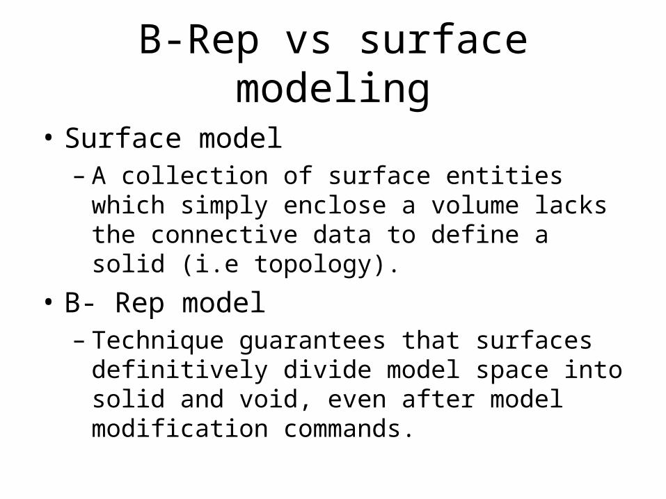
B-Rep vs surface modeling
• Surface model– A collection of surface entities which simply
enclose a volume lacks the connective data to define a solid (i.e topology).
• B- Rep model– Technique guarantees that surfaces definitively
divide model space into solid and void, even after model modification commands.

B-Rep data structure
• B-Rep graph store face, edge and vertices as nodes, with pointers, or branches between the nodes to indicate connectivity.
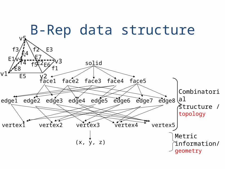
B-Rep data structure
solid
face1 face2 face3 face4 face5
edge1 edge2 edge3 edge4 edge5 edge6 edge7 edge8
vertex1 vertex2 vertex3 vertex4 vertex5
f1
f2f3
f4 f5E1
E2
E3E4
E5
E6E7
E8v1 v2
v3v4
v5
(x, y, z)
Combinatorial structure / topology
Metric information/ geometry

disediakan oleh Suriati bte Sadimon GMM, FSKSM, UTM, 2004
• Capability to construct unusual shapes that would not be possible with the available CSG aircraft fuselages, swing shapes
• Less computational time to reconstruct the image
Boundary representation- advantages

disediakan oleh Suriati bte Sadimon GMM, FSKSM, UTM, 2004
• Requires more storage • More prone to validity failure than CSG• Model display limited to planar faces
and linear edges - complex curve and surfaces only
approximated
Boundary representation- disadvantages
disediakan oleh Suriati bte Sadimon GMM, FSKSM, UTM, 2004
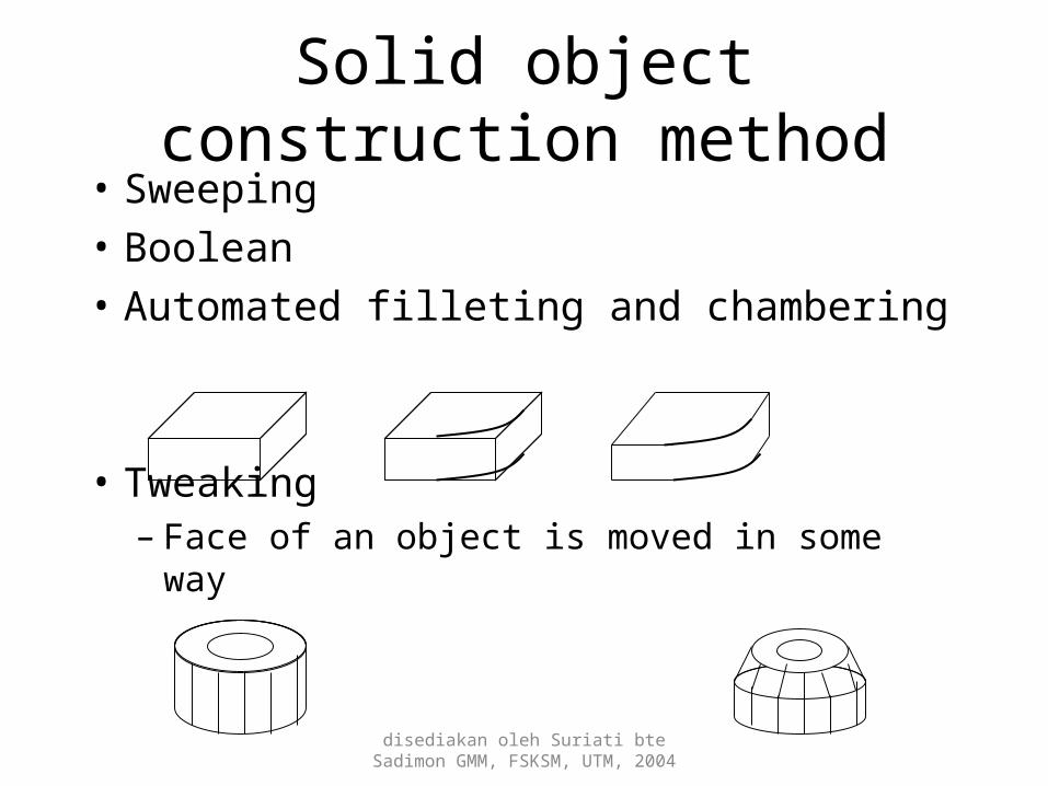
Solid object construction method• Sweeping• Boolean • Automated filleting and chambering
• Tweaking– Face of an object is moved in some way