Modeling the Space Elevator – A Project Oriented Approach ... · Approach for Teaching...
10
Modeling the Space Elevator – A Project Oriented Approach for Teaching Experimental Power Electronics Thomas Friedli, Simon D. Round, Johann W. Kolar Power Electronic Systems Laboratory ETH Zurich, Physikstrasse 3 Zurich, 8092, Switzerland Tel.: +41 / (44) – 632 28 33 Fax: +41 / (44) – 632 12 12 E-Mail: [email protected] URL: http://www.pes.ee.ethz.ch Keywords «Solar Climber», «Power Electronics», «Teaching», «Space Elevator», «Experimental». Abstract The “Solar Climber”, a model version of the space elevator, is a great project to introduce students to power electronics. In this project the students are faced with the elementary engineering problem of powering a vehicle (an electro-mechanical system) from a limited energy source such as a solar panel in this case. Apart from learning about and building a simple buck converter as their first power electronics system, they must also identify the interdependences between a limited energy source, energy conversion efficiency, weight and climbing speed. A buck converter is required to convert a solar panel’s output to a voltage level suitable for the electric motors that drive the elevator towards “space”. This paper describes the motivation, the model space elevator, the learning outcomes and the experiences from this project. Further practical solar power projects, the solar car and mains interface, are presented that have proven to be excellent projects for teaching experimental power electronics. Introduction The topic of energy and especially renewable forms of energy is gaining much attention around the world due to global warming. Into the future there will be much greater importance placed on using renewable forms of energy such as solar and wind energy. The energy from these sources will most likely be transported as electrical energy and power electronics will play a significant part in providing efficient electrical energy conversion [1]. Therefore, it is important to introduce electrical engineering students to the concepts of power electronics and renewable energy at an earlier stage in their studies. At our Power Electronic Systems Laboratory (PES) of ETH Zurich, we have introduced a number of practical power electronic projects that are suitable for students in their first two years of study. Our strategy is to base the projects on an interesting, appealing and instructional subject area in order to encourage students into power electronics [2]. The latest project is inspired by the NASA-sponsored space elevator (Fig. 1(a) & (b)) [3]. The space elevator concept proposes to use a carbon nanotube cable connected between the earth and a counterweight in space to allow a vehicle to travel to space and back. The vehicle moves on the cable using electric motors and the power is produced from solar panels that are illuminated by a ground based laser. The space elevator faces significant technical challenges such as producing a cable with a low mass and high breaking strain. Our latest project is a model version of the space elevator, and we call it the “Solar Climber” (Fig. 1(c)). In this project the students are faced with the problem of powering a vehicle from a limited energy source. Their main task is to construct a buck converter to supply the driving motors that enable the Solar Climber to climb up along two cables towards “space”. In addition, the students learn about photovoltaic systems and energy conversion. Modeling the Space Elevator – A Project Oriented Approach for Teaching Experimental Power Electronics FRIEDLI Thomas EPE 2007 - Aalborg ISBN : 9789075815108 P.1
Transcript of Modeling the Space Elevator – A Project Oriented Approach ... · Approach for Teaching...
Modeling the Space Elevator – A Project Oriented Approach for Teaching Experimental Power Electronics
Thomas Friedli, Simon D. Round, Johann W. Kolar Power Electronic Systems Laboratory
ETH Zurich, Physikstrasse 3 Zurich, 8092, Switzerland
Tel.: +41 / (44) – 632 28 33 Fax: +41 / (44) – 632 12 12
E-Mail: [email protected] URL: http://www.pes.ee.ethz.ch
Keywords «Solar Climber», «Power Electronics», «Teaching», «Space Elevator», «Experimental».
Abstract The “Solar Climber”, a model version of the space elevator, is a great project to introduce students to power electronics. In this project the students are faced with the elementary engineering problem of powering a vehicle (an electro-mechanical system) from a limited energy source such as a solar panel in this case. Apart from learning about and building a simple buck converter as their first power electronics system, they must also identify the interdependences between a limited energy source, energy conversion efficiency, weight and climbing speed. A buck converter is required to convert a solar panel’s output to a voltage level suitable for the electric motors that drive the elevator towards “space”. This paper describes the motivation, the model space elevator, the learning outcomes and the experiences from this project. Further practical solar power projects, the solar car and mains interface, are presented that have proven to be excellent projects for teaching experimental power electronics.
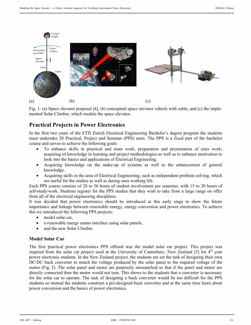
Introduction The topic of energy and especially renewable forms of energy is gaining much attention around the world due to global warming. Into the future there will be much greater importance placed on using renewable forms of energy such as solar and wind energy. The energy from these sources will most likely be transported as electrical energy and power electronics will play a significant part in providing efficient electrical energy conversion [1]. Therefore, it is important to introduce electrical engineering students to the concepts of power electronics and renewable energy at an earlier stage in their studies. At our Power Electronic Systems Laboratory (PES) of ETH Zurich, we have introduced a number of practical power electronic projects that are suitable for students in their first two years of study. Our strategy is to base the projects on an interesting, appealing and instructional subject area in order to encourage students into power electronics [2]. The latest project is inspired by the NASA-sponsored space elevator (Fig. 1(a) & (b)) [3]. The space elevator concept proposes to use a carbon nanotube cable connected between the earth and a counterweight in space to allow a vehicle to travel to space and back. The vehicle moves on the cable using electric motors and the power is produced from solar panels that are illuminated by a ground based laser. The space elevator faces significant technical challenges such as producing a cable with a low mass and high breaking strain. Our latest project is a model version of the space elevator, and we call it the “Solar Climber” (Fig. 1(c)). In this project the students are faced with the problem of powering a vehicle from a limited energy source. Their main task is to construct a buck converter to supply the driving motors that enable the Solar Climber to climb up along two cables towards “space”. In addition, the students learn about photovoltaic systems and energy conversion.
Modeling the Space Elevator – A Project Oriented Approach for Teaching Experimental Power Electronics FRIEDLI Thomas
EPE 2007 - Aalborg ISBN : 9789075815108 P.1
(a) (b) (c)
Counter-weight
Earth
SpaceElevator
Cable
Geosynchro-nous Orbit
Centerof Mass
Fig. 1: (a) Space elevator proposal [4], (b) conceptual space elevator vehicle with cable, and (c) the imple-mented Solar Climber, which models the space elevator.
Practical Projects in Power Electronics In the first two years of the ETH Zurich Electrical Engineering Bachelor’s degree program the students must undertake 20 Practical, Project and Seminar (PPS) units. The PPS is a fixed part of the bachelor course and serves to achieve the following goals:
• To enhance skills in practical and team work, preparation and presentation of ones work; acquiring of knowledge in learning and project methodologies as well as to enhance motivation to look into the basics and applications of Electrical Engineering.
• Acquiring knowledge on the make-up of systems as well as the enhancement of general knowledge.
• Acquiring skills in the area of Electrical Engineering, such as independent problem solving, which are useful for the studies as well as during ones working life.
Each PPS course consists of 28 to 56 hours of student involvement per semester, with 15 to 20 hours of self-study/work. Students register for the PPS studies that they wish to take from a large range on offer from all of the electrical engineering disciplines. It was decided that power electronics should be introduced at this early stage to show the future importance and linkage between renewable energy, energy conversion and power electronics. To achieve this we introduced the following PPS projects:
• model solar car, • a renewable energy mains interface using solar panels, • and the new Solar Climber.
Model Solar Car The first practical power electronics PPS offered was the model solar car project. This project was inspired from the solar car project used at the University of Canterbury, New Zealand [5] for 4th year power electronic students. In the New Zealand project, the students are set the task of designing their own DC/DC buck converter to match the voltage produced by the solar panel to the required voltage of the motor (Fig. 2). The solar panel and motor are purposely mismatched so that if the panel and motor are directly connected then the motor would not turn. This shows to the students that a converter is necessary for the solar car to operate. The task of designing a buck converter would be too difficult for the PPS students so instead the students construct a pre-designed buck converter and at the same time learn about power conversion and the basics of power electronics.
Modeling the Space Elevator – A Project Oriented Approach for Teaching Experimental Power Electronics FRIEDLI Thomas
EPE 2007 - Aalborg ISBN : 9789075815108 P.2

A commercially available encapsulated silicon 10 W solar panel (Solarex, MSX-10) forms the chassis of the model car (Fig. 3). Underneath the panel are mounted: a steerable, non-driven front axle; a single driven rear wheel with a directly attached cogwheel gearing and motor; the power electronics converter; and the radio-control receiver and servo for steering the car. The rear wheel is driven with a high efficiency 12 V DC motor (Maxon, RE 16) with a gear ratio of 1:7. Under best possible sunlight conditions a maximum speed of approximately 15 km/h can be achieved on smooth terrain. The steering is implemented with a commercially available, inexpensive 2-channel servo radio-control set. Custom made aluminum components are used to produce a simple, light-weight construction. At the end of the project the students participate in a race to determine the fastest car or best “tuned” converter, just as in the project at the University of Canterbury. The race provides some added incentive to do well in the PPS. However, the disadvantage with the solar car project is that it is difficult to hold a race at the end of the winter semester due to the lack and/or intensity of the sunlight. Therefore, alternative solar power projects are required that use an indoor artificial light source.
Fig. 2: Solar car energy flow block diagram.
(a) (b)
Fig. 3: Model solar car (a) front and (b) rear view (dimensions: 41 cm x 35 cm x 10 cm, weight: 2.5 kg).
Solar Power Mains Interface One alternative indoor project is the Solar Power Mains Interface PPS. In this case the energy generated by a solar panel is injected back into the mains by the power electronics interface. This project gives the students the basic understanding of the requirements and necessary power electronics to interface renewable energy sources with the mains supply. The project is made safe by employing a low voltage 50 Hz transformer as the mains interface, therefore only exposing the students to a maximum of 12 V AC. The power electronics is more advanced as the interface requires two power converters (Fig. 4), a DC/DC converter and then a DC/AC converter designed for 30 W. The students learn about maximum power point (MPP) tracking that is implemented in a microcontroller. The main challenges are to understand, assemble and test the power electronic hardware and to program an efficient MPP tracking algorithm. Designed for similar specifications as the solar car, the same solar panel can be used to supply the mains interface with the required electric energy.
Modeling the Space Elevator – A Project Oriented Approach for Teaching Experimental Power Electronics FRIEDLI Thomas
EPE 2007 - Aalborg ISBN : 9789075815108 P.3

A minor disadvantage with this project is that it is static and the result appears only on the oscilloscope or multi-meter. It also lacks any competitive aspects that makes the project exciting and allows a general audience to view it. Therefore, the challenge was to find a solar power electronics project that combines the advantages of both the solar car and the mains interface project and raises interesting and instructional technical questions.
Fig. 4: Schematic of the solar power mains interface.
Model Solar Climber Project The aim was to develop a solar power based power electronics project that highlights the fundamental technical problem of powering a vehicle from a limited energy source. This problem is motivated by many different industrial applications found in the automotive and aerospace industries. A vertically operating vehicle such as the Solar Climber, which needs to provide the energy to lift its own weight, is particularly suitable to identify the dependencies of a limited energy source, energy conversion efficiency, weight and consequently climbing speed. In addition, the project should stimulate the imagination and engineering capabilities of the students, have or incorporate an attractive and competitive component, and even possibly increase student numbers [6] taking power electronics. The Solar Climber PPS fulfils all of these requirements. The power electronic system is very similar to the solar car project, in that a solar panel is interfaced to the motor drive units via a buck converter. The only difference is that there are now two motors to drive the climber up the cable (Fig. 5).
DriveUnit
DC
DC
Cables
Buck Converter(MPP Tracking)
DriveUnit
Solar Panel
Light Source Fig. 5: Solar Climber block diagram showing the energy flow. The main objective for the students is to construct a working buck converter for use on the Solar Climber. The physical climber, shown in Fig. 6, is provided for them. The challenge was to design a climber that had a modular building principle that allows easy access to the individual components. The electro-mechanical construction should be completely transparent to enable the student to have a good understanding of the complete system, i.e. “no magic black-box hardware”. The construction had to be
Modeling the Space Elevator – A Project Oriented Approach for Teaching Experimental Power Electronics FRIEDLI Thomas
EPE 2007 - Aalborg ISBN : 9789075815108 P.4

lightweight so that a small, low power (10 W) solar panel could be used to power the Solar Climber from a relatively standard light source. A radio control system is required to switch-off the drive motors when the climber reaches the top and the unit can return due to its own weight. Most importantly, despite the requirements of a light-weight design the system has to be safe, robust and reliable. The final electro-mechanical construction should have a professional appearance with the aim (hopefully) to positively inspire the students to care for their own future hardware designs.
DC Motor
Buck ConverterSolar Panel
Drive Mechanism
Cables Radio Control2.5 kW Daylight Light Source
Fig. 6: Photograph of the implemented Solar Climber.
Electro-mechanical Construction The electro-mechanical design and construction is based on preliminary analysis including energy conversion efficiency calculations and measurements of the individual components, such as the solar panel efficiency of 15%, the energy conversion efficiency of the DC/DC converter of 90%, and 50% for the electromechanical energy conversion efficiency. The challenge was to find a design that could adequately drive the model Solar Climber up the top of the cable with the limited energy available from the solar panel and the poor total conversion efficiency from light to mechanical drive energy. The key problem to solve was reducing the weight of the Solar Climber. The photograph in Fig. 6 shows the final Solar Climber, where the electric motors and driving mechanisms form a self-supporting aluminum frame that is then attached to the cables. From the aluminum frame there is a supporting rod that extends out from both sides of the cables. On one end of the rod the solar panel is attached and on the other end, to counter-balance the panel weight, the buck converter and radio-control electronics are placed. Different cable and drive concepts were evaluated. Two individual cables proved to be most advantageous as they can be easily installed and prevent the Solar Climber from rotating around its vertical axis. Low cost coaxial 50 Ω cables were selected as they are strong and have a plastic outer sheath that provides adequate grip with the drive mechanism. A further advantage of the coaxial cables is that no additional signal cables are required for attaching a time measurement system for the race. The conductors of the coaxial cable can directly be used to transfer the sensor signal from the top of the cable to the ground-based time measurement unit. However, the implemented drive mechanism allows also the use of wire ropes or even round metal bars. Two individual electrically coupled drives are implemented, one per cable. With this design an intricate mechanical coupling between both sides can be avoided. Each drive
Modeling the Space Elevator – A Project Oriented Approach for Teaching Experimental Power Electronics FRIEDLI Thomas
EPE 2007 - Aalborg ISBN : 9789075815108 P.5

unit consists of a high efficiency 12 V DC motor (Maxon, RE-max 21), a gear set and a simple clamp-based drive mechanism with two pulleys. The cable is fed in between these two pulleys, which are driven with spur gears in opposite directions and enables optimal traction. The contact pressure and therefore the friction can be adjusted with an additional set screw. The gear ratio of 1:33 is determined based on the available average power during a climbing run when the overall energy conversion efficiency and the total weight of the Solar Climber is considered. With this design it can be guaranteed that the motors are operated close to their optimal operating point. The Solar Climber can easily be attached to or removed from the cables by simply releasing two cotters and opening the whole drive unit (Fig. 7). This allows the removal of the cables from the clamping mechanism.
(a) (b) (c)
Fig. 7: Implemented drive mechanism: (a) closed showing the spur gear side, (b) motor and drive gear side and attached to the cable (closed), and (c) open drive mechanism.
Power Electronics The core piece of the electric circuit is the buck converter which has a relatively simple construction in order to fit the project into the allocated PPS project time. A simplified analogue MPP controller is implemented with a PWM IC maintaining the converter input voltage at a predefined level. The desired MPP voltage can be adjusted with a potentiometer. The students have to select their own power semiconductors and passive components for the analogue MPP control, wind their own inductor and finally assemble all components on a pre-manufactured PCB. Fig. 8 shows a typical completed converter and its circuit schematic. While climbing upwards the converter supplies the motors with the maximum possible power provided by the panel. When the top is reached the converter can be switched-off by radio control and the Solar Climber glides downwards with a passive resistive brake.
(a) (b)
Fig. 8: (a) Photograph of a completed buck converter, (b) circuit schematic where the grey shaded components are contained in the PWM IC (IC1).
Modeling the Space Elevator – A Project Oriented Approach for Teaching Experimental Power Electronics FRIEDLI Thomas
EPE 2007 - Aalborg ISBN : 9789075815108 P.6

Light Source and Solar Panel The light source and the solar panel are essential components of the Solar Climber system. The light source spectrum needs to match the spectral range of the solar panel. Furthermore, a narrow beam characteristic is required in order to provide enough light power density over a distance of 10 m. Most of the tested light sources with lens focus system had too many optical losses. A xenon daylight lamp (Arri, Arrisun 2.5) with an input power of 2.5 kW and a parabolic reflector was found to be a most effective light source, and it is easily available for rental as it is used in multi-media industry. Weight was a key problem in selecting a suitable solar panel as commercially available modules are typically encapsulated in glass and framed with aluminum, which leads to a weight of approximately 1 kg per 10 W. Flexible solar cells made from amorphous silicon would have been inadequate due to their relatively large area and they are not suitable for concentrated light beams. The solution was to use a custom panel with crystalline silicon encapsulated and welded in between transparent foil and synthetic material.
Table I: Solar Climber Technical Specification and Component Summary
Solar panel 3S Swiss Solar Systems, crystalline Si solar panel, series connection of 36 individual cells Characteristics: 11 W, 17.5 VMPP (for standard test conditions: 1000 W/m2, AM 1.5)
Dimensions: 33 cm x 33 cm x 0.3 cm
Weight including mounting: 400 g
Drive units 2 x 12 V DC motors, Maxon RE-max 21 series, gearing ratio 1:33
Clamp-based drive mechanism with pulleys
Power electronics Buck converter with analog MPP control
Main component summary:
C1 Aluminum electrolytic capacitor 470 μF / 35 V D1 Diode, 3 A / 60 V L1 Inductor, EPCOS E 20/10/6, material N27, gap 0.25 mm, (e.g. 200 μH) S1 N-MOSFET, IRF640, 200V / 18 A (This is an over-dimensioned component, but it is readily available and has a relatively low cost.) VR1 Variable resistor, 10 kΩ IC1 PWM IC, UCC3823NA – switching frequency above 20 kHz Control components: R1 = 2k0, R2 =3k9, C2 = 470n
Average climbing speed ≅ 0.5 m/s
Overall dimensions 95 cm x 33 cm x 28 cm
Weight 1.1 kg
Light source Arri, Arrisun 2.5, 2.5 kW daylight xenon discharge lamp
Cable system 2 x 10 m parallel guided 50 Ω coaxial cables with a spacing of 15 cm
Modeling the Space Elevator – A Project Oriented Approach for Teaching Experimental Power Electronics FRIEDLI Thomas
EPE 2007 - Aalborg ISBN : 9789075815108 P.7

Learning Outcomes The previous knowledge of the students is limited since they are in their first two years of study. Therefore, the project aims to provide education in:
• the space elevator concept including the problem of weight, • energy conversion from light to electricity through the use of photovoltaic cells, • the considerations on the spectrum of the light source and the sensitivity of the solar panel, • conversion from electrical to mechanical energy (including relationships and efficiency), • comprehension of the limited power source to weight trade-off for the Solar Climber design, • the selection of the motor and mechanical drive concept, • the need of power electronic interface such as a buck converter, • the need for maximum power point (MPP) tracking to obtain optimal operation of a power limited
solar panel. The main tasks of the students are:
• the understanding of energy conversion and power electronic hardware, • the undertaking of efficiency calculations, weight considerations, and climbing speed, • to learn to use simulation tools to model the converter system, • to gain experience with practical work such as making measurements, learning to solder and
construct systems, and undertake testing.
Solar Climber PPS Schedule and Implementation Due to the limited time the students spend on the PPS project the schedule for the PPS is well defined. Initially, there is a kick-off meeting where the project task is communicated and background knowledge is given. The project teams are formed and the project plan is generated. After that meeting the following tasks are undertaken by the students:
• Measurement of solar panel, determination of the MPP and deriving a model of the solar panel. • Introduction to basic DC/DC converters and in particular gaining an understanding of the buck
converter. • Use of applets to visualize the buck converter and the MPP operating principle. • Using a Simplorer simulation of buck converter and MPP control to understand the influence
different component choices have on the system. • Calculation exercises to deepen the theoretical knowledge about the buck converter. • Dimensioning of the components such as the switching frequency, power semiconductors,
inductors, and control parameters. • Construction of the buck converter. • Testing and optimization using a resistive load. • Mounting of the buck converter on the Solar Climber and testing and optimizing using a gantry
with cables. • Writing the final project report that presents the problem solving strategy, the challenges and the
results. • Completing a feedback questionnaire to assess the project content and schedule, the tutoring, and
the students personal appraisal of their learning success in order to further improve the Solar Climber project with every implementation
• Finally, the Solar Climber Contest is held in the High Voltage laboratory (10 m climbing height), Fig. 9, to determine the team with the fastest Solar Climber.
Modeling the Space Elevator – A Project Oriented Approach for Teaching Experimental Power Electronics FRIEDLI Thomas
EPE 2007 - Aalborg ISBN : 9789075815108 P.8

Fig. 9: Photograph of a Solar Climber Race in the High Voltage Laboratory. The installed crane is used to lift up the top cable mounting.
Feedback and Project Extension The Solar Climber is an excellent project to introduce students to power electronics, renewable energy, and solar power systems. The students typically enjoy the project as revealed by the positive feedback reports from the students and by the popularity of enrolment in the PPS. This positive feedback is similar to that of other project orientated teaching programs reported in the literature [7, 8]. Based on this success the number of Solar Climbers has now been increased from 2 to 4 and the solar project can now be carried out in both the summer and winter semesters. For more advanced students it provides the option to increase the degree of difficulty by allowing different converter types to be used and for the student to undertake the complete design of the power electronic system. If vertical installation is not possible due to lack of an available high room, the climber can also be installed on a cable system with a small vertical incline. Another option for outdoor application is to enlarge the solar panel area and to go for an even more reduced construction weight to power it directly with sunlight rather than an artificial source. If the degree of difficulty is reduced and more guided instructions are provided the Solar Climber project is also applicable for college students, with limited range of knowledge in electronics. The Solar Climber project has been adapted and transformed into a seminar week project for high school students, which is used to inspire them to learn more about the engineering disciplines available at ETH Zurich. The aim was to present typical tasks on a project based problem in order to encourage students to study electrical engineering after having finished high school. During this seminar week a group of 20 people consisting of 5 teams are given the task to construct the buck converter similar to the Solar Climber project. Contrary to the PPS, each group is supervised by its individual tutor. At the end of the week each group had to present their result and the Solar Climber race, held in the university main building, is then the highlight and conclusion to the program.
Modeling the Space Elevator – A Project Oriented Approach for Teaching Experimental Power Electronics FRIEDLI Thomas
EPE 2007 - Aalborg ISBN : 9789075815108 P.9

Conclusion The use of the PPS allows the students to focus on a project concept and has the advantage of providing the possibility to work on a whole system instead of doing individual laboratory experiments. The Solar Climber incorporates different aspects of power electronics into one single system and has the positive effect of providing a competition between the groups, as well as giving the possibility for the students to gain practical experience at an early stage of their education. In addition, it provides experience and understanding of the relationships of converting light into mechanical energy using power electronics. Furthermore, a key problem in engineering is addressed of powering an electro-mechanical system from a limited energy source.
References [1] Japanese Ministry of Economy, Trade and Industry: Strategic technology roadmap (energy sector), 2005 [2] Van der Broeck H.: Students build their own switched mode power supplies or how to promote power electronics
at the universities, 9th European Conf. on Power Electronics and Applications, 2001 [3] http://www.elevator2010.org, accessed 3 Nov. 2006 [4] http//en.wikipedia.org., accessed 3 Nov. 2006 [5] Duke R.M. and Round S.D.: Converter design for a model solar car, Proc. 10th Conf. on Power Electronics &
Motion Control, CDROM T12-014 pp 1-7, 2002 [6] Round S.D. and Duke R.M.: A strategy for increasing undergraduate power engineering course enrolments, Proc.
of Tomorrow’s Education in Electrical Technology Conference pp II-31 – II-36, 2001 [7] Koch P.: A project-oriented master programme in DSP algorithms and ASIC architectures, Microelectronic
Systems Education, 1999 [8] Cruz-Rivera J.L.: A project orientated approach to teaching software-hardware integration of microcontroller-
based systems, Frontiers in Education Conf. pp 64-68, 1998
Modeling the Space Elevator – A Project Oriented Approach for Teaching Experimental Power Electronics FRIEDLI Thomas
EPE 2007 - Aalborg ISBN : 9789075815108 P.10