Modeling the Characteristics of Propulsion Systems Providing Less Than 10 N Thrust
142
Modeling the Characteristics of Propulsion Systems Providing Less Than 10 N Thrust Thomas M. Chiasson, Paulo C. Lozano May 2012 SSL#8-12 1
Transcript of Modeling the Characteristics of Propulsion Systems Providing Less Than 10 N Thrust

Modeling the Characteristics of Propulsion Systems
Providing Less Than 10 N Thrust
Thomas M. Chiasson, Paulo C. Lozano
May 2012 SSL#8-12
1

2

Modeling the Characteristics of Propulsion Systems
Providing Less Than 10 N Thrust
Thomas M. Chiasson, Paulo C. Lozano
May 2012 SSL#8-12
1
1This work is based on the unaltered text of the thesis by Thomas M. Chiasson submitted to theDepartment of Aeronautics and Astronautics in partial fulfillment of the requirements for the degreeof Master of Science in Aeronautics and Astronautics at the Massachusetts Institute of Technology.
3

4

Abstract
A methodology has been created that estimates the characteristics and mass
breakout of a propulsion system providing less than 10 N of thrust, including thruster,
propellant, propellant management, and supporting power system. The methodology
allows the user to choose between 18 different types of propulsion and propellant,
including chemical and electric thrusters. Thruster mass and characteristics are es-
timated using a database of historical specifications, and the rest of the propulsion
system is estimated using standard design equations. Description and analysis of
the methodology, including validation and example applications, are included. A
methodology has been created that estimates the characteristics and mass breakout
of a propulsion system providing less than 10 N of thrust, including thruster, pro-
pellant, propellant management, and supporting power system. The methodology
allows the user to choose between 18 different types of propulsion and propellant,
including chemical and electric thrusters. Thruster mass and characteristics are es-
timated using a database of historical specifications, and the rest of the propulsion
system is estimated using standard design equations. Description and analysis of the
methodology, including validation and example applications, are included.
5

Acknowledgments
This work was performed primarily under contract FA70001020040 with the US Air
Force/Space and Missile System Center (SMC) as part of the Space Engineering
Research program. The work was also performed for contract AFS11-0343 Aurora
with DARPA System F6 Technical Area 4. The author gratefully thanks the sponsors
for their generous support that enabled this research. The author also thanks Prof.
Paulo Lozano and Prof. David Miller from MIT, and Dr. Jim Sisco and Dr. Jaime
Ramirez at Aurora Flight Sciences for their support and guidance.
6

Contents
1 Introduction 15
2 Fundamentals of Space Propulsion 19
3 Predicting Relationships from Historical Data 23
3.1 Cold Gas Thrusters . . . . . . . . . . . . . . . . . . . . . . . . . . . . 26
3.2 Monopropellant Thrusters . . . . . . . . . . . . . . . . . . . . . . . . 30
3.3 Bipropellant Thrusters . . . . . . . . . . . . . . . . . . . . . . . . . . 36
3.4 Resistojets . . . . . . . . . . . . . . . . . . . . . . . . . . . . . . . . . 38
3.5 Arcjets . . . . . . . . . . . . . . . . . . . . . . . . . . . . . . . . . . . 43
3.6 Ion Engines . . . . . . . . . . . . . . . . . . . . . . . . . . . . . . . . 49
3.7 Hall Effect Thrusters . . . . . . . . . . . . . . . . . . . . . . . . . . . 51
3.8 Pulsed-Plasma Thrusters . . . . . . . . . . . . . . . . . . . . . . . . . 54
3.9 Vacuum Arc Thrusters . . . . . . . . . . . . . . . . . . . . . . . . . . 56
3.10 Field-Emission Electric Propulsion . . . . . . . . . . . . . . . . . . . 56
3.11 Colloid Thrusters . . . . . . . . . . . . . . . . . . . . . . . . . . . . . 59
3.12 Electrospray Thrusters . . . . . . . . . . . . . . . . . . . . . . . . . . 61
4 Modeling Propellant Storage and Management 63
5 Validation 67
5.1 Aerojet Cubesat Propulsion Module . . . . . . . . . . . . . . . . . . . 67
5.2 BepiColombo Ion Engines . . . . . . . . . . . . . . . . . . . . . . . . 69
7

5.3 University of Minnesota Shackleton Crater Reconnaisance Mission Bipro-
pellant System . . . . . . . . . . . . . . . . . . . . . . . . . . . . . . 70
5.4 Clyde Space PPT Module . . . . . . . . . . . . . . . . . . . . . . . . 70
6 Applications 73
7 Conclusion 79
A Thruster Data 83
B Source Code 105
8

List of Figures
3-1 Historical data for xenon Hall thrusters. . . . . . . . . . . . . . . . . 24
3-2 Historical data for hydrazine monopropellant thrusters. . . . . . . . . 25
3-3 Historical data for cold gas thrusters. Most of the data is gathered
from using nitrogen gas, and the outlier is from using helium. . . . . 27
3-4 Historical data for cold gas thrusters. . . . . . . . . . . . . . . . . . . 28
3-5 Historical data for cold gas thrusters. . . . . . . . . . . . . . . . . . . 28
3-6 Historical data for cold gas thrusters. . . . . . . . . . . . . . . . . . . 29
3-7 Historical data for cold gas thrusters, looking at just the low thrust
regime. . . . . . . . . . . . . . . . . . . . . . . . . . . . . . . . . . . . 29
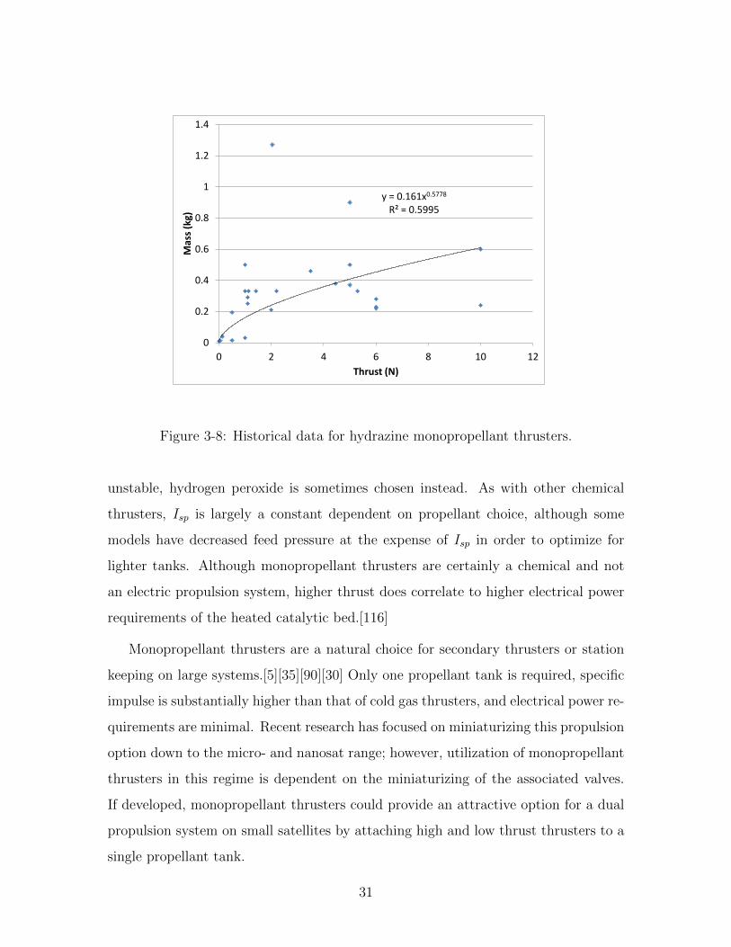
3-8 Historical data for hydrazine monopropellant thrusters. . . . . . . . . 31
3-9 Historical data for hydrazine monopropellant thrusters. . . . . . . . . 32
3-10 Historical data for hydrazine monopropellant thrusters. . . . . . . . . 32
3-11 Historical data for hydrazine monopropellant thrusters. . . . . . . . . 33
3-12 Historical data for hydrogen peroxide monopropellant thrusters. . . . 33
3-13 Historical data for hydrogen peroxide monopropellant thrusters. . . . 34
3-14 Historical data for hydrogen peroxide monopropellant thrusters. . . . 34
3-15 Historical data for hydrogen peroxide monopropellant thrusters. . . . 35
3-16 Historical data for bipropellant thrusters. . . . . . . . . . . . . . . . . 37
3-17 Historical data for bipropellant thrusters. . . . . . . . . . . . . . . . . 37
3-18 Historical data for hydrazine resistojets. . . . . . . . . . . . . . . . . 39
3-19 Historical data for hydrazine resistojets. . . . . . . . . . . . . . . . . 39
3-20 Historical data for hydrazine resistojets. . . . . . . . . . . . . . . . . 40
3-21 Historical data for hydrazine resistojets. . . . . . . . . . . . . . . . . 40
9

3-22 Historical data for water resistojets. . . . . . . . . . . . . . . . . . . . 41
3-23 Historical data for water resistojets. . . . . . . . . . . . . . . . . . . . 41
3-24 Historical data for water resistojets. . . . . . . . . . . . . . . . . . . . 42
3-25 Historical data for water resistojets. . . . . . . . . . . . . . . . . . . . 42
3-26 Historical data for arcjets using various propellants. . . . . . . . . . . 44
3-27 Historical data for arcjets using various propellants, zooming in on the
low thrust regime. . . . . . . . . . . . . . . . . . . . . . . . . . . . . . 45
3-28 Historical data for ammonia arcjets. . . . . . . . . . . . . . . . . . . . 45
3-29 Historical data for ammonia arcjets. . . . . . . . . . . . . . . . . . . . 46
3-30 Historical data for hydrogen arcjets. . . . . . . . . . . . . . . . . . . . 46
3-31 Historical data for hydrogen arcjets. . . . . . . . . . . . . . . . . . . . 47
3-32 Historical data for hydrazine arcjets. . . . . . . . . . . . . . . . . . . 47
3-33 Historical data for hydrazine arcjets. . . . . . . . . . . . . . . . . . . 48
3-34 Historical data for hydrazine arcjets. . . . . . . . . . . . . . . . . . . 48
3-35 Historical data for hydrazine arcjets. . . . . . . . . . . . . . . . . . . 49
3-36 Historical data for xenon ion engines. . . . . . . . . . . . . . . . . . . 50
3-37 Historical data for xenon ion engines. . . . . . . . . . . . . . . . . . . 50
3-38 Historical data for xenon ion engines. . . . . . . . . . . . . . . . . . . 51
3-39 Historical data for xenon Hall thrusters. . . . . . . . . . . . . . . . . 52
3-40 Historical data for xenon Hall thrusters. . . . . . . . . . . . . . . . . 53
3-41 Historical data for xenon Hall thrusters. . . . . . . . . . . . . . . . . 53
3-42 Historical data for PPTs. . . . . . . . . . . . . . . . . . . . . . . . . . 54
3-43 Historical data for PPTs. . . . . . . . . . . . . . . . . . . . . . . . . . 55
3-44 Historical data for PPTs. . . . . . . . . . . . . . . . . . . . . . . . . . 55
3-45 Historical data for FEEPs. . . . . . . . . . . . . . . . . . . . . . . . . 57
3-46 Historical data for FEEPs. . . . . . . . . . . . . . . . . . . . . . . . . 58
3-47 Historical data for FEEPs. . . . . . . . . . . . . . . . . . . . . . . . . 58
3-48 Historical data for colloid thrusters. . . . . . . . . . . . . . . . . . . . 59
3-49 Historical data for colloid thrusters. . . . . . . . . . . . . . . . . . . . 60
3-50 Historical data for colloid thrusters. . . . . . . . . . . . . . . . . . . . 60
10

6-1 Results from application of a preliminary version of the program for
the System F6 project. . . . . . . . . . . . . . . . . . . . . . . . . . . 73
6-2 Using the program to compare propulsion options for a 100 kg space-
craft. Electrosprays are not compared. Mass fractions over 90% are
not shown. . . . . . . . . . . . . . . . . . . . . . . . . . . . . . . . . . 74
6-3 Using the program to compare propulsion options for a 100 kg space-
craft, including electrosprays. Mass fractions over 90% are not shown. 75
6-4 Using the program to compare propulsion options for a 10 kg space-
craft. Electrosprays are not compared. Mass fractions over 90% are
not shown. . . . . . . . . . . . . . . . . . . . . . . . . . . . . . . . . . 76
6-5 Using the program to compare propulsion options for a 10,000 kg space-
craft. Electrosprays are not compared. Mass fractions over 99% are
not shown. . . . . . . . . . . . . . . . . . . . . . . . . . . . . . . . . . 77
11

12

List of Tables
3.1 Thrusters included in the database. . . . . . . . . . . . . . . . . . . . 24
3.2 Specifications of VACCO MiPS butane thruster unit with integrated
propellant tank for cubesats.[38] . . . . . . . . . . . . . . . . . . . . . 30
3.3 Specifications of Alameda Applied Sciences Corporation µVAT for Illi-
nois Observing NanoSatellite (ION). . . . . . . . . . . . . . . . . . . 56
3.4 Specifications of MIT Space Propulsion Lab’s electrospray arrays. . . 62
4.1 Choosing a tank material. . . . . . . . . . . . . . . . . . . . . . . . . 64
5.1 Comparison of results from program with actual propulsion systems. . 68
A.1 Cold gas thrusters . . . . . . . . . . . . . . . . . . . . . . . . . . . . . 83
A.2 Cold gas thrusters with liquid propellant (mass includes integrated tank) 85
A.3 Hydrazine monopropellant thrusters . . . . . . . . . . . . . . . . . . . 86
A.4 Hydrogen peroxide monopropellant thrusters . . . . . . . . . . . . . . 88
A.5 Bipropellant thrusters . . . . . . . . . . . . . . . . . . . . . . . . . . 88
A.6 Water resistojets . . . . . . . . . . . . . . . . . . . . . . . . . . . . . 89
A.7 Hydrazine resistojets . . . . . . . . . . . . . . . . . . . . . . . . . . . 90
A.8 Ammonia arcjets . . . . . . . . . . . . . . . . . . . . . . . . . . . . . 90
A.9 Hydrogen arcjets . . . . . . . . . . . . . . . . . . . . . . . . . . . . . 91
A.10 Hydrazine arcjets . . . . . . . . . . . . . . . . . . . . . . . . . . . . . 91
A.11 Ion engines . . . . . . . . . . . . . . . . . . . . . . . . . . . . . . . . 92
A.12 Hall Thrusters . . . . . . . . . . . . . . . . . . . . . . . . . . . . . . . 94
A.13 Pulsed plasma thrusters . . . . . . . . . . . . . . . . . . . . . . . . . 98
13

A.14 Vacuum arc thrusters . . . . . . . . . . . . . . . . . . . . . . . . . . . 101
A.15 Field emission electric propulsion . . . . . . . . . . . . . . . . . . . . 102
A.16 Colloid thrusters . . . . . . . . . . . . . . . . . . . . . . . . . . . . . 103
14

Chapter 1
Introduction
In spacecraft design, scaling equations are often used to estimate the mass of a system
for preliminary design purposes. Although well developed scaling equations have long
been used for space lift or orbit insertion propulsion systems, few if any can be applied
to the low thrust regime.[35] Thrusters providing less than 10 N of thrust are currently
the focus of the majority of research and development on space propulsion.[115][36]
These systems range from integrated tank, thruster, and power processing units for
cubesats, to interplanetary travel, to extremely fine precision control. They are even
more diverse in the means that they provide propulsion; the database that has been ac-
cumulated in the course of this research includes models (specific historical thrusters)
categorized into eleven distinct types of propulsion, electrical and chemical, using a
variety of propellants, with several other propulsion concepts for which not enough
data could be gathered to form equations.
However, the systems level designers are usually not interested in how the thruster
works, they care about what it will provide to their spacecraft in terms of thrust
and total velocity change and what it will cost in terms of mass, power, volume,
risk, or money. These numbers require an initial design phase in which the type
of propulsion is chosen and some initial calculations are done to estimate how large
the thruster, propellant storage, and (if necessary) electrical power system will be.
In scenarios when designers want to compare several different spacecraft options, of
which propulsion is only one term in a larger equation, this process can be tedious.
15

Perhaps the designer wants to run some simulations of several different options for
the space system in which the number of satellites and their masses are varying,
drastically changing the propulsion requirements, or perhaps some initial calculations
need to be run to compare the merits of one propulsion system against another to
make an initial design decision. The variety of propulsion options often makes these
situations like comparing apples and oranges. The fact that there is ongoing research
into improving and miniaturizing virtually every type of propulsion only makes these
decisions even more difficult, stressing the need for the most current data.[70][71]
This project was initially started to answer the seemingly simple question of how
spacing in a satellite cluster would cause the collision avoidance requirements to
change the mass fraction of their propulsion systems. A program that quickly and
reliably estimated the mass fraction of propulsion systems featuring monopropellant,
cold gas, and Hall thrusters based off required acceleration, total change in velocity
(∆V ), and initial satellite mass was created as part of a parametric model that
would run several thousand scenarios. The program was then used to help simulate
scattering and regathering the cluster. Surprisingly, the results indicated that such
operations would be feasible even for satellites under 10 kg using dual high thrust
and low thrust monopropellant propulsion systems. Furthermore, since the program
was created from the ground up using historical data, there was already information
gathered on actual thrusters on the market that could conceivably be a part of such
a system.
Since then, the program has been expanded to include eighteen different propul-
sion and propellant options built off of data gathered from over 300 thruster models
ranging from 10 N to to 10 µN of maximum thrust. It can be run iteratively within a
larger program, or it can be used stand alone: any situation where a designer requires
a quick estimate of required power or mass of a propulsion system (including thruster,
propellant, propellant management, and power system) given the initial mass of the
spacecraft and the required ∆V and maximum acceleration. Data has also been gath-
ered on specific impulse, efficiency, minimum impulse bit, and feed pressure, although
only specific impulse and feed pressure go into the mass calculations and efficiency
16

and minimum impulse bit could not be found for a few thrusters.
This thesis will describe how the program was created, including the database of
thruster specifications, equations that were developed from the database, equations
used to model the other parts of a propulsion system, a few necessary assumptions,
validation, and some interesting applications.
17

18

Chapter 2
Fundamentals of Space Propulsion
Before an examination of the program itself it would be useful to review some funda-
mentals of space propulsion. Space propulsion at the most basic level is the applica-
tion of Newton’s third law by expelling mass at a rate m and velocity c to propel a
spacecraft in the opposite direction. In propulsion, the resulting force is called thrust
(T ).
T = m · c (2.1)
While thrust relates to how quickly a spacecraft can change velocity, in orbital
mechanics it is often useful to describe maneuvers in terms of total velocity change
(∆V ) required to move the spacecraft from one orbit to another. These two variables,
thrust and ∆V , tend to dictate propulsion choice from a design standpoint. Large
spacecraft, short schedules, or rapid maneuvering will require higher thrust from a
propulsion system, whereas drag cancellation, non-elliptical orbits, and long mission
times and/or distances will require larger ∆V .[66]
∆V is by definition dependent on the mass of propellant (mprop) expelled from the
propulsion system. This relationship is described in the rocket equation, where mS/C
is the initial mass of the spacecraft including propellant and g is the acceleration of
19

9.81 m/s2 due to gravity.
mprop = mS/C(1− e−∆V/Ispg) (2.2)
As can be seen from this equation, specific impulse (Isp) is also a determining
factor of a spacecraft’s propellant mass fraction. Isp describes the amount of thrust
derived from a propulsion system compared to the mass flow rate of its exhaust (m).
Isp =T
m · g(2.3)
Although the concepts are different, the relationship between ∆V and Isp is analo-
gous to that between distance and miles per gallon. Missions requiring high ∆V must
use propulsion systems with high Isp in order to keep the propellant mass fraction
from being prohibitively large. Unfortunately, propulsion systems with high Isp tend
to have low thrust to power ratios.
For the purposes of this thesis, power refers to the electric power input of a
propulsion system. All propulsion systems require some minimal amount of power
to operate valves and possibly heaters or pumps, but some propulsion systems use
electric power to create thrust, as opposed to depending on chemical reactions. The
thrust of these electric propulsion systems is directly dependent on the input power.
Increasing the power in turn requires a power system, including a power source
such as batteries and/or solar panels and a power processing unit. All spacecraft
require a power system regardless of propulsion, but electric propulsion systems can
have power requirements high enough to significantly increase the mass of a space-
craft’s power system. In practice, this means that electric propulsion systems provide
limited thrust.
This brings up a fundamental distinction between electric and chemical propul-
sion. Chemical propulsion provides unmatched thrust, whereas no electric propulsion
system has ever been designed that can lift the weight of its own required power sys-
tem off the surface of the planet. However, electric propulsion far surpasses chemical
propulsion in terms of Isp, resulting in less propellant and making them the natural
20
choice for high ∆V missions, such as interplanetary travel.
Another important factor in propulsion system design is the propellant manage-
ment system. Depending on the propellant used (which also depends on the type of
propulsion), multiple tanks may be required. The pressurization of propellant tanks
is also important, and an optimal low mass balance must be found between large
thin-walled tanks and small thick-walled tanks. For some types of propulsion sys-
tems, thrust or Isp may be dependent on the feed pressure of the propellant into the
thruster.
21

22

Chapter 3
Predicting Relationships from
Historical Data
The foundation of the modeling process is a spreadsheet containing specifications of
all the models of thrusters providing 10 N or less of thrust that could be found. Data
has been collected on 385 specific thruster models. Best fit equations were then found
to represent the relationships between different system characteristics. For example,
Figure 3-1 shows the relationship of thrust to efficiency for Hall thrusters. Each point
represents data gathered from a real world Hall thruster, while the curve is a best fit
of the historical data, which is used to predict system characteristics in the modeling
process.
This approach is time intensive due to the difficulty of finding published speci-
fications for many thrusters; however, it ensures that the modeling process is using
hard data gathered from real world systems to compare thruster options. Of course,
it does not guarantee that every thruster designed will also fit this historical data.
In some case, the data was so chaotic that it was difficult or impossible to find a re-
lationship between certain system specifications, and a flat average was used instead
of an equation. Figure 3-2 gives an example of data that was just barely organized
enough to find an equation for. In this case, it was decided that although some of the
data points were drastically different from the best fit curve, using the equation of
the curve would still be preferable to taking a flat average. So although the historical
23

Table 3.1: Thrusters included in the database.
Thruster Number of Models
Cold Gas (gas) 32Cold Gas (liq) 3
Monopropellant (H4N2) 32Monopropellant (H2O2) 7
Bipropellant (liq) 9Resistojet (H2O) 9
Resistojet (H4N2) 7Arcjet (NH3) 7
Arcjet (H2) 5Arcjet (H4N2) 11Arcjet (other) 4
Ion Engine (Xe) 37Hall Thruster (Xe) 81
PPT 63VAT (Cr) 4
FEEP 18Colloid 13
Unused 43
Total 385
y = 0.8441x3 - 0.0386x2 + 18.768x + 0.1972 R² = 0.9694
0
10
20
30
40
50
60
70
80
0 0.5 1 1.5 2 2.5 3 3.5
Po
we
r (k
W)
Thrust (N)
Figure 3-1: Historical data for xenon Hall thrusters.
24

y = 0.161x0.5778 R² = 0.5995
0
0.2
0.4
0.6
0.8
1
1.2
1.4
0 2 4 6 8 10 12
Mas
s (k
g)
Thrust (N)
Figure 3-2: Historical data for hydrazine monopropellant thrusters.
data provides the best starting point for generating a quick initial estimate of the
characteristics of an undesigned system, it should be kept in mind that once such a
system is actually designed, its characteristics could be very different, for better or
for worse.
Special care was taken to ensure that the equations were most accurate for lower
levels of thrust, where slight differences in mass have a more serious impact on the
system as a whole. Sometimes the thrusters were divided into two different regimes
and separate equations were developed for both. However, the low thrust end of
thruster technology is currently a focus of much research, meaning that low thrust
data is few and far between, has often been gathered from experimental models, and
is subject to change in the near future.[36] However, the data gathered is still more
useful that what can be predicted by extrapolating from larger thrusters. Low thrust
technology often uses innovative designs employing different technology and throws
out assumptions that are essential to traditional methods of thruster design, which
have been developed for the high thrust regime.[115]
25

It is important to stress that although this method uses real world data, it will not
necessarily output the specifications of an actual real world thruster. The results from
this method are representative of all of the thrusters researched and will probably not
be an exact match of any of them specifically. These results are better thought of as
the specifications of a theoretical thruster that could be built given what has been
built in the past. Some of the thrusters in the database have not yet been flown or
are engineering models of thrusters still in development, but they still provide useful
data points on what can be achieved. In light of this, special care was taken not to
propagate relationships beyond the limits of the data that has been gathered. If a
thruster providing less than 1 N of thrust has never been built, this program will not
try to conjure up what such a thruster might look like. But if thrusters providing 1
and 2 N have been built, this program will predict the characteristics of a thruster
that provides 1.5 N. On the other hand, if the required thrust is higher than that
of any existing model, then the program will divide the thrust until it is in range
of existing models and design a system that includes multiple thrusters but unified
propellant and power systems.
If the user wants to know what the options are in terms of thrusters that have
already been built, the database itself is still a very useful starting point. Past users
have been able to validate results of this program by finding thrusters in the database
that are on the market and provide even better performance than what the program
estimates.
In conclusion, while the relationships developed from this database of historical
data are not perfect, they are the most logical starting point for providing a solid
backbone of historical data to the model. As will be discussed, each propulsion type
provided its own unique set of challenges.
3.1 Cold Gas Thrusters
Cold gas thrusters are the simplest type of thruster. Pressurized gas is simply released
through a nozzle to create thrust. Specific impulse (Isp) is largely a function of
26
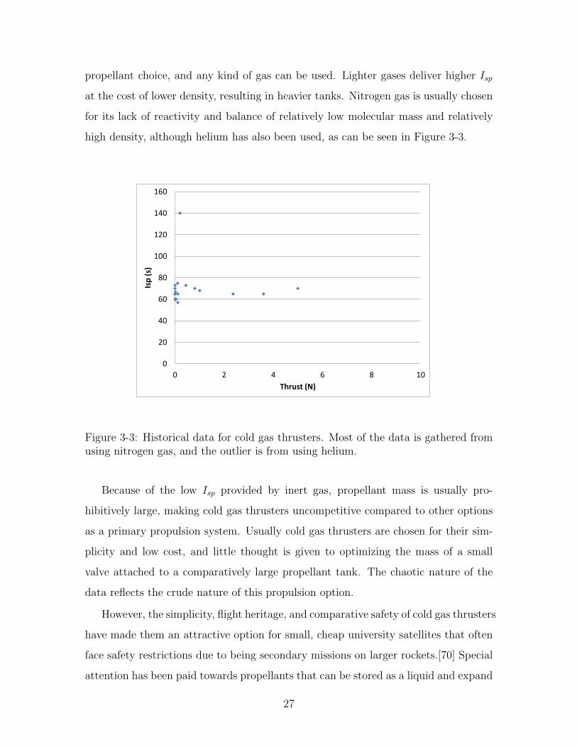
propellant choice, and any kind of gas can be used. Lighter gases deliver higher Isp
at the cost of lower density, resulting in heavier tanks. Nitrogen gas is usually chosen
for its lack of reactivity and balance of relatively low molecular mass and relatively
high density, although helium has also been used, as can be seen in Figure 3-3.
0
20
40
60
80
100
120
140
160
0 2 4 6 8 10
Isp
(s)
Thrust (N)
Figure 3-3: Historical data for cold gas thrusters. Most of the data is gathered fromusing nitrogen gas, and the outlier is from using helium.
Because of the low Isp provided by inert gas, propellant mass is usually pro-
hibitively large, making cold gas thrusters uncompetitive compared to other options
as a primary propulsion system. Usually cold gas thrusters are chosen for their sim-
plicity and low cost, and little thought is given to optimizing the mass of a small
valve attached to a comparatively large propellant tank. The chaotic nature of the
data reflects the crude nature of this propulsion option.
However, the simplicity, flight heritage, and comparative safety of cold gas thrusters
have made them an attractive option for small, cheap university satellites that often
face safety restrictions due to being secondary missions on larger rockets.[70] Special
attention has been paid towards propellants that can be stored as a liquid and expand
27

0
0.05
0.1
0.15
0.2
0.25
0.3
0.35
0.4
0 2 4 6 8 10
Mas
s (k
g)
Thrust (N)
Figure 3-4: Historical data for cold gas thrusters.
0
5
10
15
20
25
30
35
40
0 2 4 6 8 10
Po
we
r (W
)
Thrust (N)
Figure 3-5: Historical data for cold gas thrusters.
28

0
2
4
6
8
10
12
14
16
18
0 2 4 6 8 10
Fee
d P
ress
ure
(M
Pa)
Thrust (N)
Figure 3-6: Historical data for cold gas thrusters.
y = 0.088ln(x) + 0.7413 R² = 0.3686
0
0.1
0.2
0.3
0.4
0.5
0.6
0.7
0.8
0 0.02 0.04 0.06 0.08 0.1 0.12
Fee
d P
ress
ure
(M
Pa)
Thrust (N)
Figure 3-7: Historical data for cold gas thrusters, looking at just the low thrustregime.
29

into a gas during emission. Liquefied gas thruster packages with integrated propellant
tanks and nozzles have recently been developed specifically for cubesats.[71]
Most of the characteristics of cold gas thrusters were predicted by simply averaging
the data that was gathered, since no relationships could be found except for Isp, which
is a constant dependent on propellant choice. For feed pressure, which is the driving
factor of tank mass (a dominating part of propellant heavy cold gas systems), an
equation was developed specifically for the low thrust regime. Even this equation is
a poor fit of the data, but it is more accurate than a flat average across the entire
range of thrust.
The program offers three propellant options for cold gas thrusters: nitrogen, he-
lium, or butane (stored as a liquid). The characteristics for nitrogen and helium
thrusters are identical except for the Isp. The characteristics for butane thrusters are
gathered from VACCO’s MiPS thruster shown in Table 3.1. (Only three models of
liquefied gas thrusters could be found, the data on this model was the most complete,
and it is currently on the market for use on cubesats.) All characteristics except for
feed pressure for low thrust helium and nitrogen thrusters are constant.
Propellant ButaneMax Thrust (mN) 55Mass (g) 456Isp (s) 65Min Impulse Bit (mNs) 0.25Max Propellant Storage (g) 53
Table 3.2: Specifications of VACCO MiPS butane thruster unit with integrated pro-pellant tank for cubesats.[38]
3.2 Monopropellant Thrusters
Monopropellant thrusters use the chemical decomposition of a single propellant, his-
torically either hydrazine or hydrogen peroxide, to create thrust. The propellant
flows through a heated catalytic bed in the combustion chamber to initiate the re-
action. Hydrazine delivers a higher specific impulse, but because it is toxic and
30
y = 0.161x0.5778 R² = 0.5995
0
0.2
0.4
0.6
0.8
1
1.2
1.4
0 2 4 6 8 10 12
Mas
s (k
g)
Thrust (N)
Figure 3-8: Historical data for hydrazine monopropellant thrusters.
unstable, hydrogen peroxide is sometimes chosen instead. As with other chemical
thrusters, Isp is largely a constant dependent on propellant choice, although some
models have decreased feed pressure at the expense of Isp in order to optimize for
lighter tanks. Although monopropellant thrusters are certainly a chemical and not
an electric propulsion system, higher thrust does correlate to higher electrical power
requirements of the heated catalytic bed.[116]
Monopropellant thrusters are a natural choice for secondary thrusters or station
keeping on large systems.[5][35][90][30] Only one propellant tank is required, specific
impulse is substantially higher than that of cold gas thrusters, and electrical power re-
quirements are minimal. Recent research has focused on miniaturizing this propulsion
option down to the micro- and nanosat range; however, utilization of monopropellant
thrusters in this regime is dependent on the miniaturizing of the associated valves.
If developed, monopropellant thrusters could provide an attractive option for a dual
propulsion system on small satellites by attaching high and low thrust thrusters to a
single propellant tank.
31

y = 206.21x0.048 R² = 0.5934
140
160
180
200
220
240
0 2 4 6 8 10 12
Isp
(s)
Thrust (N)
Figure 3-9: Historical data for hydrazine monopropellant thrusters.
y = 0.0026e0.0311x R² = 0.7599
0
0.5
1
1.5
2
2.5
3
3.5
4
140 160 180 200 220 240
Fee
d P
ress
ure
(M
Pa)
Isp (s)
Figure 3-10: Historical data for hydrazine monopropellant thrusters.
32

y = 28.684x0.7943 R² = 0.8878
0
5
10
15
20
25
30
35
40
0 0.2 0.4 0.6 0.8 1 1.2 1.4
Po
we
r (W
)
Mass (kg)
Figure 3-11: Historical data for hydrazine monopropellant thrusters.
y = 0.0077e1.4637x R² = 0.5954
0
0.01
0.02
0.03
0.04
0.05
0.06
0.07
0 0.2 0.4 0.6 0.8 1 1.2
Mas
s (k
g)
Thrust (N)
Figure 3-12: Historical data for hydrogen peroxide monopropellant thrusters.
33

y = 136.76x0.0649 R² = 0.6005
100
110
120
130
140
150
160
0 0.2 0.4 0.6 0.8 1 1.2
Isp
(s)
Thrust (N)
Figure 3-13: Historical data for hydrogen peroxide monopropellant thrusters.
y = 0.1034e0.011x R² = 0.8267
0
0.1
0.2
0.3
0.4
0.5
0.6
0.7
80 100 120 140 160
Fee
d P
ress
ure
(M
Pa)
Isp (s)
Figure 3-14: Historical data for hydrogen peroxide monopropellant thrusters.
34
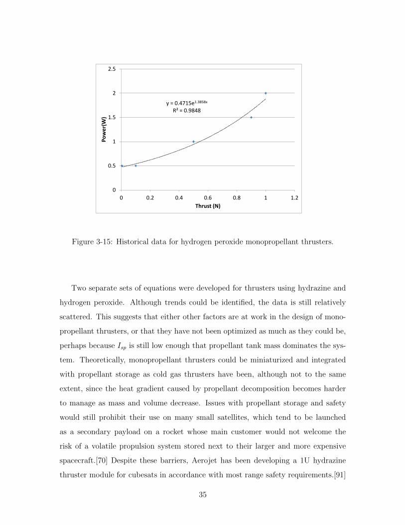
y = 0.4715e1.3858x R² = 0.9848
0
0.5
1
1.5
2
2.5
0 0.2 0.4 0.6 0.8 1 1.2
Po
we
r(W
)
Thrust (N)
Figure 3-15: Historical data for hydrogen peroxide monopropellant thrusters.
Two separate sets of equations were developed for thrusters using hydrazine and
hydrogen peroxide. Although trends could be identified, the data is still relatively
scattered. This suggests that either other factors are at work in the design of mono-
propellant thrusters, or that they have not been optimized as much as they could be,
perhaps because Isp is still low enough that propellant tank mass dominates the sys-
tem. Theoretically, monopropellant thrusters could be miniaturized and integrated
with propellant storage as cold gas thrusters have been, although not to the same
extent, since the heat gradient caused by propellant decomposition becomes harder
to manage as mass and volume decrease. Issues with propellant storage and safety
would still prohibit their use on many small satellites, which tend to be launched
as a secondary payload on a rocket whose main customer would not welcome the
risk of a volatile propulsion system stored next to their larger and more expensive
spacecraft.[70] Despite these barriers, Aerojet has been developing a 1U hydrazine
thruster module for cubesats in accordance with most range safety requirements.[91]
35

3.3 Bipropellant Thrusters
Bipropellant thrusters, the powerhouses of space propulsion, use the chemical reaction
of two propellants to create thrust. These thrusters are unmatched in terms of thrust
to weight ratio and boast the highest Isp of any type of purely chemical propulsion.
However, they are also the most complicated chemical propulsion option, requiring
two propellant tanks and the associated equipment required for pressurization and
fuel delivery.
While often the only viable option for space lift and orbit insertion, the complex-
ity of bipropellant thrusters does not lend itself to miniaturization and low thrust
applications. Thrusters that do provide less than 10 N are usually used as secondary
propulsion, and as the chaotic nature of the data suggests, have not been optimized for
mass.[27][23][5] While there has been initial investigation into miniaturizing bipropel-
lant thrusters using microelectricmechanical systems (MEMS) technology, propellant
storage is still a barrier to implementation.[71][56]
On the other end of the spectrum, electric propulsion often outperforms bipropel-
lant thrusters on large satellites if the ∆V requirement is high. While bipropellant
thrusters have the highest Isp out of any chemical propulsion option, it is still far sur-
passed by most electric propulsion options. A high ∆V requirement often demands
a high Isp to keep the propellant and tank masses from becoming prohibitively large.
These factors restrict bipropellant thrusters to high thrust operations, most of which
are over 10 N and outside the scope of this research.
Although data from all available models was averaged to predict thruster charac-
teristics, the program assumes monomethylhydrazine as fuel and nitrogen tetroxide
as oxidizer in its propellant storage calculations. Power requirements were only found
for one thruster and feed pressures were only found for two.
36

0
0.1
0.2
0.3
0.4
0.5
0.6
0.7
0.8
0 2 4 6 8 10 12 14
Mas
s (k
g)
Thrust (N)
Figure 3-16: Historical data for bipropellant thrusters.
270
275
280
285
290
295
300
305
310
315
320
325
0 2 4 6 8 10 12 14
Isp
(s)
Thrust (N)
Figure 3-17: Historical data for bipropellant thrusters.
37

3.4 Resistojets
Resistojets improve the performance of cold gas thrusters by heating the propellant
using electric resistors. This method raises the Isp of the thruster, decreasing the
tank and propellant masses, but adds the complexity and mass associated with the
electrical power requirements.
The first widely used resistojets were actually modified monopropellant thrusters,
and as a hybrid of chemical and electrical thrusters were called electrothermally aug-
mented hydrazine thrusters (EHTs). The development of EHTs arose from the conver-
gence of stringent mass limits and surplus power supply on communication satellites
that were already using monopropellant hydrazine thrusters.[35][90][30] However, re-
sistojets can use inert gas as well. Often propellants that can be stored as a liquid
and easily vaporized are chosen, such as water or ammonia.
The heat augmentation process raises Isp up to a point and then levels out, mean-
ing that the specific impulse of resistojets is largely a function of propellant choice.
There is a relatively strong correlation between thrust and power, although low power
resistojets can have abnormally high thrust to power ratios due to the mechanical
thrust provided by propellant pressure.
Resistojets are often chosen instead of cold gas thrusters in cases where spare
electrical power is already available. This similarity of application with cold gas
thrusters, combined with the greater variety of propellants used, makes the data
difficult to analyze.
Resistojets are also amiable to miniaturization for the same reasons as cold gas
thrusters, although limits are reached due to the difficulty of transferring heat to
the propellant within a smaller chamber. The increase in specific impulse and using
liquid propellant can keep mass low, however, this must be balanced against the
higher power requirements. On the high thrust end of the spectrum, resistojets are
limited by the material properties of the heating element, a barrier which is overcome
by arcjets.
Two sets of equations for resistojets have been developed, one for hydrazine and
38

y = 373.54x2 + 770.3x + 52.949 R² = 0.7676
0
100
200
300
400
500
600
700
800
900
1000
0 0.2 0.4 0.6 0.8 1
Po
we
r (W
)
Thrust (N)
Figure 3-18: Historical data for hydrazine resistojets.
y = 0.1119x0.2762 R² = 0.6562
0
0.1
0.2
0.3
0.4
0.5
0.6
0.7
0.8
0.9
1
0 200 400 600 800 1000
Mas
s (k
g)
Power (W)
Figure 3-19: Historical data for hydrazine resistojets.
39
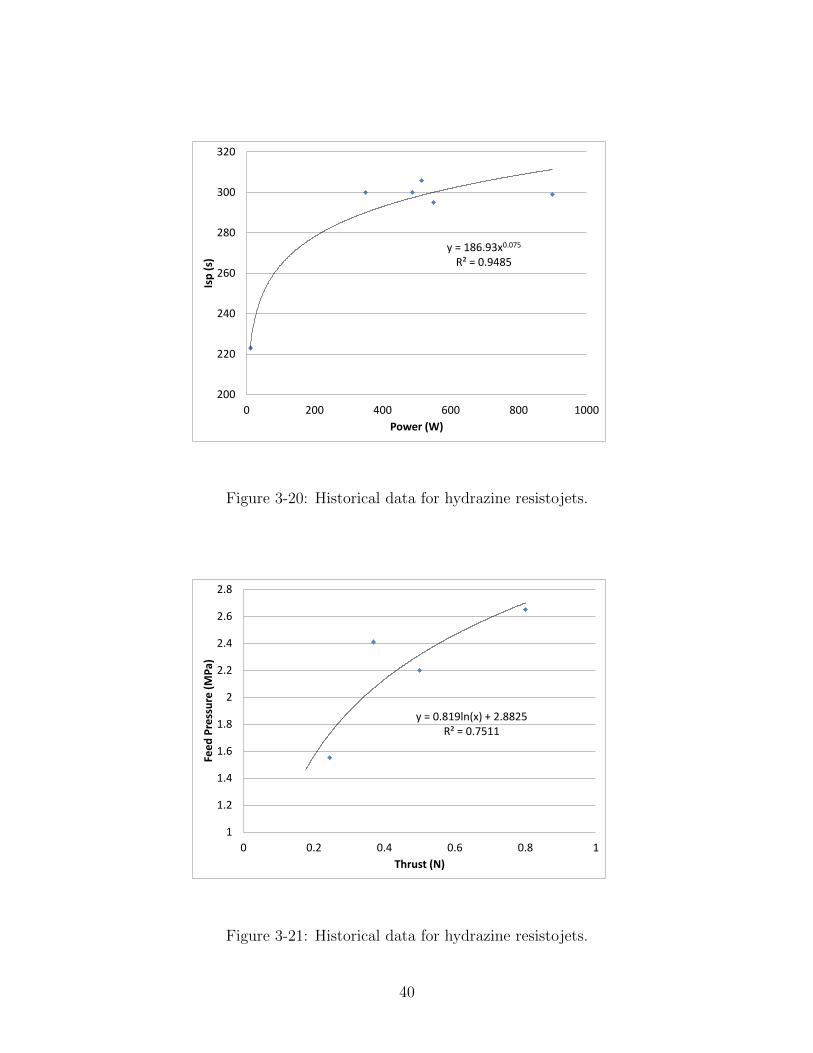
y = 186.93x0.075 R² = 0.9485
200
220
240
260
280
300
320
0 200 400 600 800 1000
Isp
(s)
Power (W)
Figure 3-20: Historical data for hydrazine resistojets.
y = 0.819ln(x) + 2.8825 R² = 0.7511
1
1.2
1.4
1.6
1.8
2
2.2
2.4
2.6
2.8
0 0.2 0.4 0.6 0.8 1
Fee
d P
ress
ure
(M
Pa)
Thrust (N)
Figure 3-21: Historical data for hydrazine resistojets.
40

y = 5156.5x1.2627 R² = 0.9263
0
200
400
600
800
1000
1200
1400
1600
0 0.05 0.1 0.15 0.2 0.25 0.3 0.35 0.4
Po
we
r (W
)
Thrust (N)
Figure 3-22: Historical data for water resistojets.
y = 0.0149x0.7736 R² = 0.5818
0
0.5
1
1.5
2
2.5
3
3.5
0 200 400 600 800 1000
Mas
s (k
g)
Power (W)
Figure 3-23: Historical data for water resistojets.
41

100
120
140
160
180
200
220
240
0 200 400 600 800 1000
Isp
(s)
Power (W)
Figure 3-24: Historical data for water resistojets.
y = 4.1265x + 0.1122 R² = 0.4415
0.0
0.5
1.0
1.5
2.0
2.5
0 0.05 0.1 0.15 0.2 0.25 0.3 0.35 0.4
Fee
d P
ress
ure
(M
Pa)
Thrust (N)
Figure 3-25: Historical data for water resistojets.
42

one for water. The sparse data for water resistojets raises the question as to whether
they could be further optimized for small satellites, since they don’t carry the risks
that monopropellants do. Resistojets also enjoy an abundance of other propellant
options that could open up further possibilities. A team at the University of Arkansas
recently developed a 1U resistojet propulsion module for cubesats that uses R-134a
refrigerant.[69]
3.5 Arcjets
Arcjets are very similar to resistojets but use an electric arc to heat propellant instead
of resistors. This allows for higher input power thresholds and correspondingly higher
thrust and specific impulse, although efficiency is compromised. As with resistojets,
ammonia is a common propellant choice. Despite the storage problems associated
with light gases, some research has focused on creating high power hydrogen arcjets
with the expectation that large manned space systems would have an excess on board
due to boil off from cryogenically stored hydrogen.[7]
As with resistojets, the first arcjets used hydrazine to take the place of hydrazine
monopropellant thrusters. In a monopropellant hydrazine thruster, hydrazine is de-
composed into ammonia and nitrogen in an extremely exothermic reaction, while
some fraction of ammonia is further decomposed into nitrogen and hydrogen in an
endothermic reaction. Good design minimizes this fraction in order to keep the ex-
haust gases as hot as possible. However, the addition of heat in resistojets and arcjets,
while more than compensating for the heat lost in the decomposition of ammonia, can
actually raise the fraction decomposed to the point that there is no real difference be-
tween using hydrazine and hydrogen nitrogen mixture as propellant.[66] In hydrazine
arcjets, for example, the heat added through electrical means totally decomposes the
ammonia and drowns out much of the benefit that the first chemical decomposition
of hydrazine might still have to offer. The question designers are faced with is why
to use hydrazine at all given its toxicity and instability. Isp is still dependent on
propellant choice, especially at high power levels, but it is the molecular mass of the
43

y = 0.7834x0.9677 R² = 0.6326
0
10
20
30
40
50
60
70
80
0 20 40 60 80 100 120
Mas
s (k
g)
Power (kW)
Figure 3-26: Historical data for arcjets using various propellants.
propellant (or its products after decomposition) that are decisive rather than any
chemical reaction.
Arcjets straddle the middle ground between purely chemical bipropellant thrusters
and high powered Hall thrusters or ion engines in terms of Isp and required power,
striking a balance between tank mass and power system mass. As with resistojets,
the modeling process is complicated by the variety of the propellants used, but the
high dependency performance characteristics have on electrical power makes the data
much more organized. Three sets of equations have been developed for ammonia,
hydrogen, and hydrazine propellants. Unfortunately, no mass data could be found
for ammonia or hydrogen arcjets and feed pressures could only be found for hydrazine
arcjets. The mass data for all of the arcjets, regardless of propellant, was propagated
out to the maximum power recorded to estimate thruster mass, as shown in Figures
3-26 and 3-27. It is uncertain how accurate this equation is in the high thrust, high
power regime. It is likely an overestimation of thruster mass, which typically increases
slightly less than linearly with relation to power.
44
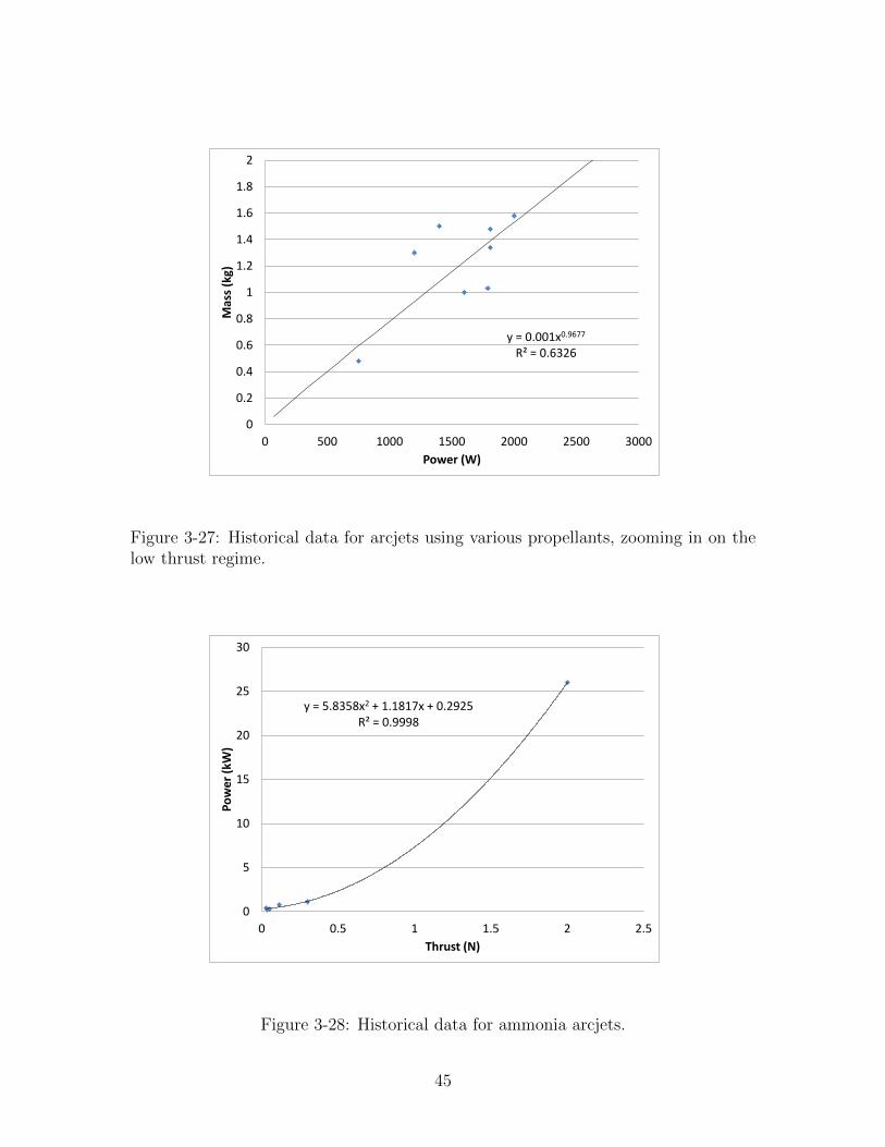
y = 0.001x0.9677 R² = 0.6326
0
0.2
0.4
0.6
0.8
1
1.2
1.4
1.6
1.8
2
0 500 1000 1500 2000 2500 3000
Mas
s (k
g)
Power (W)
Figure 3-27: Historical data for arcjets using various propellants, zooming in on thelow thrust regime.
y = 5.8358x2 + 1.1817x + 0.2925 R² = 0.9998
0
5
10
15
20
25
30
0 0.5 1 1.5 2 2.5
Po
we
r (k
W)
Thrust (N)
Figure 3-28: Historical data for ammonia arcjets.
45
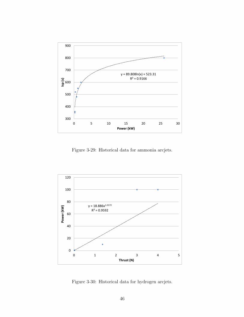
y = 89.808ln(x) + 523.31 R² = 0.9166
300
400
500
600
700
800
900
0 5 10 15 20 25 30
Isp
(s)
Power (kW)
Figure 3-29: Historical data for ammonia arcjets.
y = 18.886x1.0172 R² = 0.9592
0
20
40
60
80
100
120
0 1 2 3 4 5
Po
we
r (k
W)
Thrust (N)
Figure 3-30: Historical data for hydrogen arcjets.
46

y = 1270.6x0.1019 R² = 0.9844
600
700
800
900
1000
1100
1200
1300
1400
1500
1600
0 1 2 3 4 5
Isp
(s)
Thrust (N)
Figure 3-31: Historical data for hydrogen arcjets.
y = 1.4281ln(x) + 3.7623 R² = 0.8156
0
0.5
1
1.5
2
2.5
0.05 0.1 0.15 0.2 0.25 0.3
Po
we
r (k
W)
Thrust (N)
Figure 3-32: Historical data for hydrazine arcjets.
47

0.8
0.9
1
1.1
1.2
1.3
1.4
1.5
1.6
1.7
1 1.2 1.4 1.6 1.8 2 2.2
Mas
s (k
g)
Power (kW)
Figure 3-33: Historical data for hydrazine arcjets.
350
400
450
500
550
600
650
0 0.5 1 1.5 2 2.5
Isp
(s)
Power (kW)
Figure 3-34: Historical data for hydrazine arcjets.
48

1.45
1.5
1.55
1.6
1.65
1.7
1.75
1.8
1.85
0.05 0.1 0.15 0.2 0.25 0.3
Fee
d P
ress
ure
(MP
a)
Thrust (N)
Figure 3-35: Historical data for hydrazine arcjets.
3.6 Ion Engines
Ion engines accelerate ionized gas using an electric field created by a potential dif-
ference between two grids in order to create thrust. The gas is usually ionized using
electron bombardment or radio frequency-induced gas discharge in a chamber before
being accelerated through biased grids.
Electric propulsion in general favors propellants with high molecular mass and low
ionization potential. Early ion engines used mercury or cesium, which were largely
abandoned due to their toxicity and tendency to contaminate the spacecraft.[88] Most
ion engines today use xenon, an inert gas which is much easier to handle. The
equations have been developed using data only from xenon ion engines.
In comparison with the thrusters discussed so far, ion engines offer a much higher
specific impulse but limited thrust to power ratio. The high specific impulse translates
to propellant mass savings, but high power requirements in turn drive up the mass
of the required power system. Most models are clustered around the low power end
of the spectrum, but recent research has focused on high power models for use in
49

y = 64.664x2 + 18.216x + 0.0462 R² = 0.9848
0
5
10
15
20
25
30
35
40
45
0 0.1 0.2 0.3 0.4 0.5 0.6 0.7 0.8
Po
we
r (k
W)
Thrust (N)
Figure 3-36: Historical data for xenon ion engines.
y = 61.162x + 0.6761 R² = 0.9152
0
5
10
15
20
25
30
35
40
45
50
0 0.1 0.2 0.3 0.4 0.5 0.6 0.7 0.8
Mas
s (k
g)
Thrust(N)
Figure 3-37: Historical data for xenon ion engines.
50

y = -4.3967x2 + 357.29x + 2661.7 R² = 0.8464
0
2000
4000
6000
8000
10000
12000
0 10 20 30 40 50
Isp
(s)
Power (kW)
Figure 3-38: Historical data for xenon ion engines.
interplanetary travel.[25][39]
As with many of the electric propulsion options to be discussed, the significantly
reduced propellant mass brought on by higher Isp and the complexity of the thruster
makes the thruster itself a more significant contributor to the mass of the system as
a whole than in chemical systems. This means that ion engines have been the focus
of quite a bit of optimization, especially in the low thrust regime, and that the data
lends itself to tight, orderly relationships.
3.7 Hall Effect Thrusters
Hall thrusters accelerate ionized gas using a combination of electric and magnetic
fields in order to create thrust. Propellant is fed into a ring shaped chamber with
magnets arranged to create a radial magnetic field and an anode and cathode arranged
to created an axial electric field pointing out of the open end of the thruster. Ions
are accelerated out of the thruster towards the cathode by the axial electric field.
51

y = 0.8441x3 - 0.0386x2 + 18.768x + 0.1972 R² = 0.9694
0
10
20
30
40
50
60
70
80
0 0.5 1 1.5 2 2.5 3 3.5
Po
we
r (k
W)
Thrust (N)
Figure 3-39: Historical data for xenon Hall thrusters.
The electrons, instead of accelerating in the opposite direction towards the anode,
are trapped in a Hall current by the perpendicular electric and magnetic fields and
exert a force on the magnets which propels the thruster. Some of the electrons make
it to the anode and are in turn propelled out of the cathode to neutralize the exhaust
plume.
Xenon is usually chosen as a propellant for its high molecular mass, low ionization
potential, and because it is inert and easy to handle. The possibility of using bismuth
has been explored in high power hall thrusters for it’s even higher molecular mass,
lower ionization potential, and lower cost, often resulting in higher Isp.[92] However,
not enough data on bismuth hall thrusters exists to identify any relationships and the
equations were developed using data from only xenon Hall thrusters.
Research on Hall thrusters has been continuing for decades and is now concen-
trated on the high and low power ends of the spectrum. The consistent, ordered data
reflects the high level of effort directed towards the optimization of Hall thrusters,
and the sudden decrease in performance in the low power regime is indicative of the
52

y = 2.317x0.7786 R² = 0.9389
0
10
20
30
40
50
60
70
80
90
0 10 20 30 40 50 60 70 80
Mas
s (k
g)
Power (W)
Figure 3-40: Historical data for xenon Hall thrusters.
y = 1681.2x0.1702 R² = 0.5717
0
500
1000
1500
2000
2500
3000
3500
4000
4500
0 10 20 30 40 50 60 70 80
Isp
(s)
Power (kW)
Figure 3-41: Historical data for xenon Hall thrusters.
53

the challenges of miniaturizing this propulsion option. In general, hall thrusters offer
higher thrust but lower Isp than ion engines.
3.8 Pulsed-Plasma Thrusters
Pulsed-plasma thrusters (PPTs) also use a combination of electric and magnetic fields
to accelerate propellant. Arc discharges are pulsed through the propellant, which is
accelerated by the force created from the current of the discharge and its associated
magnetic field.
PPTs are low thrust, low efficiency, and low Isp compared to ion engines. Their
advantage is their simplicity and low power requirements. Most models use solid
Teflon as propellant, which is ablated and vaporized by the discharge. This makes
propellant storage on PPTs extremely simple and reliable. The low minimum impulse
bit resulting from the pulsed firing of PPTs also makes them a good choice for attitude
control.
y = 56.634x0.6868 R² = 0.867
0
50
100
150
200
250
300
0.00 1.00 2.00 3.00 4.00 5.00 6.00
Po
we
r (W
)
Thrust (mN)
Figure 3-42: Historical data for PPTs.
54

y = 4.9919x0.2567 R² = 0.2343
0
1
2
3
4
5
6
7
8
9
0.00 1.00 2.00 3.00 4.00 5.00 6.00
Mas
s (k
g)
Thrust(mN)
Figure 3-43: Historical data for PPTs.
y = 917.28x0.2391 R² = 0.4414
0
500
1000
1500
2000
2500
3000
0.00 1.00 2.00 3.00 4.00 5.00 6.00
Isp
(s)
Thrust (mN)
Figure 3-44: Historical data for PPTs.
55

Although trends can be observed in the characteristics of PPTs, the data is still
very chaotic and suggests that further optimization is possible. In addition, thrust
to power ratio was found for many high Isp models without any accompanying max
thrust or max power data, implying that these relationships are not representative of
PPTs’ full potential.
3.9 Vacuum Arc Thrusters
Vacuum Arc Thrusters (VATs) are very similar to PPTs except that the discharge
ablates propellant off of the cathode itself, which replaces the Teflon block and retains
the advantage of solid propellant storage. Performance is very similar to that of PPTs
but with higher Isp, although some models utilize permanent magnets to substantially
increase thrust. Very few VATs have been built, but they have been tested and
scheduled to fly on microsatellite missions.
Propellant ChromiumMax Thrust (mN) 1Mass (g) 100Isp (s) 2000Min Impulse Bit (µNs) 0.25
Table 3.3: Specifications of Alameda Applied Sciences Corporation µVAT for IllinoisObserving NanoSatellite (ION).
Since data on only four VATs could be gathered, two of which were augmented
with magnets and had very different characteristics, only one was chosen to represent
this propulsion option. The µVAT, built by Alameda Applied Sciences Corporation,
was chosen by the University of Illinois for deployment on their satellite, ION.
3.10 Field-Emission Electric Propulsion
A form of electrostatic propulsion like ion engines, field-emission electric propulsion
(FEEP) extracts and propels ions from liquid metal propellant (usually cesium or
56

y = 72.257x1.0456 R² = 0.9161
0
20
40
60
80
100
120
0.00 0.20 0.40 0.60 0.80 1.00 1.20 1.40 1.60
Po
we
r (W
)
Thrust (mN)
Figure 3-45: Historical data for FEEPs.
indium) using a potential difference. The potential difference causes Taylor cones on
the surface of the propellant, which in turn allows the emission of ions from the tips.
FEEPs offer the highest Isp and the smallest minimum impulse bit out of any
propulsion option, but thrust is limited to the micronewton and low millinewton
regime. Most applications of FEEPs take advantage of their low minimum impulse bit
to provide high accuracy pointing or control, but their high Isp makes them favorable
for any high ∆V, low thrust mission.
One difficulty with FEEPs is propellant management, since the indium or cesium
must be melted before emission. On the other hand, solid propellant lends itself to
simple storage, and since the thruster is emitting ions, the propellant can be fed by
capillary forces and requires no pressurization.
Except for Isp, the data for FEEPs is relatively consistent, though sparse.
57

y = 0.2141x0.6287 R² = 0.6261
0
1
2
3
4
5
6
0 20 40 60 80 100
Mas
s (k
g)
Power (W)
Figure 3-46: Historical data for FEEPs.
0
2000
4000
6000
8000
10000
12000
14000
0 20 40 60 80 100
Isp
(s)
Power (W)
Figure 3-47: Historical data for FEEPs.
58

3.11 Colloid Thrusters
Colloid thrusters are very similar to FEEPs except that they extract and accelerate
charged droplets instead of ions and use different propellant. Colloid thrusters were
one of the earliest forms of electric propulsion to be investigated, but the lack of
suitable propellants inhibited their development until the invention of liquid salts at
room temperature.
Today’s colloid thrusters offer a higher thrust to power ratio than FEEPs, ion
engines, and Hall thrusters but a lower specific impulse. A major advantage of colloid
thrusters is the ease of propellant management. Liquid salts are easily manufactured
with the right equipment, require little pressurization, and are safe to handle and
store.
y = 16.376x1.1542 R² = 0.8748
0
5
10
15
20
25
30
35
0 0.2 0.4 0.6 0.8 1 1.2
Po
we
r (W
)
Thrust (mN)
Figure 3-48: Historical data for colloid thrusters.
Unfortunately, no relationships can be discerned from the data on colloid thrusters
and flat averages must be taken in order to predict most characteristics. This is prob-
ably because most of the data is from old research before liquid salts were invented,
and is hardly indicative of the potential of colloid thrusters. Although a variety
59

0
1
2
3
4
5
6
7
8
0 1 2 3 4 5 6 7
Mas
s (k
g)
Power (W)
Figure 3-49: Historical data for colloid thrusters.
0
200
400
600
800
1000
1200
1400
1600
0 2 4 6 8 10 12
Isp
(s)
Power (W)
Figure 3-50: Historical data for colloid thrusters.
60

of propellants have been used, the program assumes the liquid salt EMI-BF4 in its
propellant storage calculations.
3.12 Electrospray Thrusters
Electrospray thrusters are conceptually identical to FEEPs except that they use liquid
salt as propellant, and identical to colloid thrusters except that they emit ions instead
of droplets. In fact, it may be possible to develop a single thruster using the same
propellant that can act as both a colloid thruster and an electrospray.
Although electrosprays offer a lot of promise, they have not yet been flown in space.
Current research has achieved thrust and specific impulse levels similar to standard
ion engines. Propellant management is identical to liquid salt colloid thrusters ex-
cept that the propellant can be passively fed into the thruster using just capillary
forces. Miniaturization of electrosprays using MEMS technology could enable them
to replace ion engines in many applications due to their low mass and easy propellant
management.
Another unique characteristic of MEMS electrosprays is their scalability. Electro-
sprays consist of hundreds of microscopic needles from which liquid salt is propelled
using a voltage difference. Scaling the thruster is simply a matter of creating more
needles. For low thrusts, this can be achieved by increasing the density of the needles,
and the mass of the thruster remains constant. At some point the a density limit is
reached and larger area is required, at which point mass will increase with thrust.
Efficiency and specific impulse remain constant throughout.[55]
Because of both their scalability and lack of historical data, this research models
electrospray thrusters using constant scaling equations instead of equations derived
from historical specifications. Even if there was extensive flight data on electrosprays,
it would be more logical to use that data to find constants for the known scaling
equations than to work entirely off of historical specifications, as has been done for
the other propulsion types. The constants used in this research were measured from
MIT Space Propulsion Laboratory’s MEMS electrosprays, which are due to be tested
61
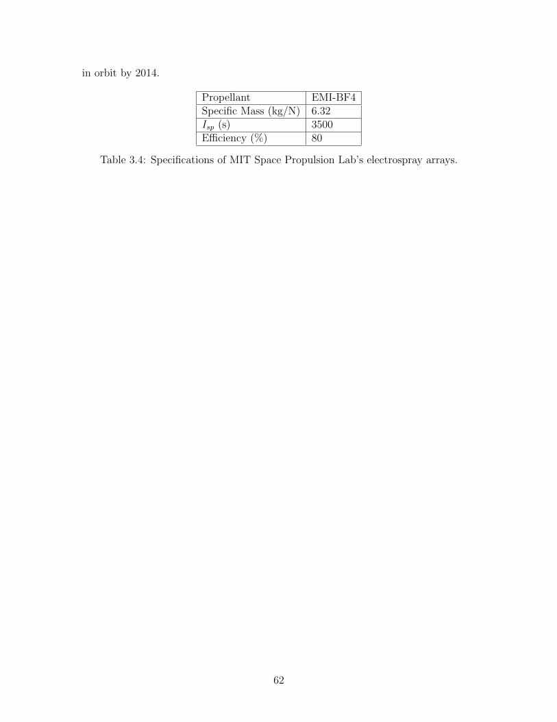
in orbit by 2014.
Propellant EMI-BF4Specific Mass (kg/N) 6.32Isp (s) 3500Efficiency (%) 80
Table 3.4: Specifications of MIT Space Propulsion Lab’s electrospray arrays.
62

Chapter 4
Modeling Propellant Storage and
Management
The database and the resulting equations provide the tools needed to quickly and
repeatedly estimate the mass of a given thruster from the required thrust. However,
as shown by the focus on developing high Isp electric propulsion systems, the mass
of the propellant and the storage and management requirements that come with it
is often a driving force in propulsion design and a deciding factor when choosing a
propulsion system. Fortunately, the physics of how much propellant is needed and
how big its tank needs to be are relatively simple.
The equations developed in the previous chapter can provide Isp. From there, the
mass of the propellant (mprop) is found from the required ∆V and the initial mass of
the spacecraft (mS/C) (provided by the user) using the rocket equation, where g is
the acceleration of 9.81 m/s2 due to gravity.
mprop = mS/C(1− e−∆V/Ispg) (4.1)
The mass of the propellant tank (mtank) is then calculated by assuming spherical
tanks with a factor of safety (FoS) of two and some given material properties. The
material properties are read from within the database and can tuned specifically to
each thruster type. Titanium alloy is preferable, but aluminum alloy was used in
63

Titanium Aluminum6Al-4V 2014-T6
Yield Strength - σyield (MPa) 924 414Density - ρtank (kg/m3) 4430 2790
Propellants Nitrogen HydrazineHelium Hydrogen PeroxideWater Hydrogen
Ammonia EMI-BF4Xenon
Table 4.1: Choosing a tank material.
light of the chemical properties of certain reactive propellants.
Under these assumptions, the mass of a propellant tank can be calculated using
the equations for thin walled pressure vessels and the volume of a sphere. All that’s
left is to find the volume (Vprop) and maximum pressure (Pmax) within the tank.
mtank =4
3π[(rtank + ttank)3 − r3tank]ρtank (4.2)
ttank = FoSPmaxrtank
2σyield(4.3)
rtank = 3
√Vprop43π
(4.4)
rtank and ttank represent the radius and wall thickness of the tank, respectively.
All tank masses calculated by this method are multiplied by two to account for
other factors such as acceleration and dynamic loads, stress concentrations, and weld
efficiencies.[35]
For thrusters that use pressurized gas (nitrogen, helium, hydrogen, and xenon), the
propellant is assumed to be an ideal gas, the minimum pressure (Pmin) is set to the feed
pressure estimated from the database, and a leftover mass of propellant (mleftoverprop)
is accounted for that will fill the propellant tank at the required minimum pressure.
The mass of the leftover propellant is added to the mass of the tank, and the following
64

equations along with equations 4.2, 4.3, and 4.4 are optimized for minimum tank mass.
mleftoverprop = minitialprop −mprop (4.5)
Vprop =mleftoverpropRT
PminM(4.6)
Pmax =minitialpropRT
VpropM(4.7)
minitialprop represents the mass of all of the propellant initially stored in the tank and
mprop represents just the mass of the propellant that’s expelled in order to achieve
the required ∆V . R, T , and M are, respectively, the universal gas constant (8.3145
J/mol/K), temperature of propellant (set to 293.15 K), and molar mass of each the
propellant (varies by propellant).
For thrusters using pressurized liquid propellant (water, ammonia, hydrazine, and
hydrogen peroxide), the propellant tank is assumed to be at constant feed pressure
and mass is estimated using equations 4.2, 4.3, and 4.4 by calculating the volume
from the density of the liquid (ρprop).
Vprop =mprop
ρprop(4.8)
A titanium nitrogen pressurant tank is then modeled using a process similar to
that for pressurized gas thrusters except that the mass of the gas (mpress) is constant,
final volume is the combined volume of the pressurant (Vtank) and propellant tanks
(Vprop), and minimum pressure is the pressure of the propellant (which has already
been set to the feed pressure for the thruster). As with the pressurized gas tank
method, the mass of the pressurant is added to the mass of the pressurant tank and
the equations are optimized with 4.2, 4.3, and 4.4 for minimum pressurant tank mass.
mpress =Pprop(Vprop + Vtank)M
RT(4.9)
Pmax =mpressRT
VtankM(4.10)
For bipropellant thrusters, two liquid propellant tanks are calculated, one for the
65

fuel and one for the oxidizer, and a single pressurant tank with enough nitrogen to
fill all three tanks at the feed pressure is calculated.
Colloid thrusters are pressurized, but only slightly. Many models use pumps
instead of pressurization, and recent models have used a compressible tank attached
to a spring. This program calculates the mass of colloid thruster tanks the same as
other liquid propellants (equations 4.2, 4.3, 4.4, 4.8) but neglects the pressurant tank.
For thrusters that do not use solid or unpressurized liquid propellants (PPTs,
VATs, FEEPs, and electrosprays) the propellant system mass was estimated to be
5% of propellant mass.
Finally, 10% is added onto the combined mass of the thruster and tanks of all
propulsion types to account for feed lines and support structures.
The mass of the power system is also estimated using an assumed power density
of 15 kg/kW. This mass includes power source and processing, and is representative
of solar panels.[35]
66

Chapter 5
Validation
Several difficulties are encountered when validating the results of the program. The
first is that complete mass breakouts of propulsion systems can be difficult to find.
The second is that when such data is found, it’s often from systems that violate
assumptions used in the program. For example, many propulsion systems use multiple
thrusters even when a single thruster with the necessary thrust has been designed,
either for redundancy or for attitude control. Some spacecraft end their missions
without using all their propellant, and the achieved ∆V actually corresponds to a
much smaller tank. Usually the tanks themselves are not spherical or made out of a
single material, which are assumed in the tank estimation process. All of these are
indicative of the fact that there are many factors in propulsion system design that this
program does not take into account, such as cost, reliability, volume, and schedule.
Quite simply, the program predicts what is possible, but not necessarily what is.
That said, comparing the results with what data can be gathered from real world
systems yields some interesting results. The four systems in Table 5.1 are those for
which the most complete specifications could be found.
5.1 Aerojet Cubesat Propulsion Module
The first system is a 1U hydrazine propulsion module being developed by Aerojet
for cubesats. This is an example of a system for which the technology exists and
67

Propulsion Type
Actual Calculated Actual Calculated Actual Calculated Actual Calculated
Thrust (N) 2.8 0.145 4 1.00E-05
dV (m/s) 450 5760 1021 30.25
Mass: S/C (kg) 2 4100 445 1
Propulsion (kg) 1.36 1.77 1155 1093.89 146.33 168.70 0.2 1.73
Propellant (kg) 0.36 0.38 560 553.95 121 133.68 0.01 0.01
Thruster (kg) 0.33 0.40
Tanks (kg) 25 31.44
Isp (s) 4300 4045.06 590 305.04
Power (W) 0.5 2.40
Max Pressure (MPa) 3.477 56.99 24.82 53.88
Tank Volume (m3) 0.07 0.065
Aerojet Cubesat
Propulsion Module BepiColombo
U of Minnesota
Shackleton Crater Clyde Space
Hydrazine
Monopropellant Xe Ion Engine
MMH/MON-1
Bipropellant Teflon PPT
Table 5.1: Comparison of results from program with actual propulsion systems.
feasible thrusters are recorded in the database, but which has never been integrated
before into such a tight package. Aerojet uses MR-140A thrusters, for which no mass
data could be found and are therefore not included in the database. The inputs
in yellow are the capabilities Aerojet advertises for this system on a hypothetical
cubesat. Although Aerojet is still working to make sure that the system meets range
safety requirements, the program confirms that the design is feasible.[91]
There are a few key differences between the system designed by Aerojet and the
one that the program predicts. First of all, Aerojet’s system is volume limited and
designed to fit entirely within a 10 cm cube, which changes the shape of the tank
from an optimal sphere. Second, Aerojet’s system cannot provide its max thrust of
2.8 N at end of life, whereas the program designs a system so that the max thrust
can still be achieved until all the propellant needed to achieve the required ∆V has
been expelled. This accounts for the vast difference in maximum tank pressures,
since both are designed with blow down propellant feed systems. The first difference
should result in Aerojet’s system being heavier, and the second should result in it
being lighter than what the program predicts. Another difference is that Aerojet’s
system actually includes four thrusters in its mass figures, but the thrust value is for
an individual thruster. The calculated numbers have been adjusted so that the mass
of the predicted thruster is multiplied by four to account for this.
68

This comparison is especially exciting because the program has predicted a system
that is on the edge of what is feasible, and it just so happens that a very similar system
is in the process of being built and tested. It validates the program’s ability to predict
systems in the low thrust regime, where much of the data is from experimental systems
and the margin for error is especially tight.
5.2 BepiColombo Ion Engines
The second system is the electric propulsion system on BepiColombo, a European
Space Agency mission to Mercury that will be launched in 2013 and will take 6
years and 5760 m/s ∆V to complete the journey from Earth. This is an example
of a fairly straightforward electric propulsion system within the range of what has
been accomplished before. It uses T6 ion engines, which are well documented in the
database.[27][111]
The data for BepiColombo was assembled from two sources which were not in
complete agreement. It is possible that the numbers were from different periods of the
design phase, or that they actually referred to different things. Mass of the propulsion
system, for example, could be taken to mean simply the mass set aside for propulsion
or the mass of the propulsion module designed to ferry the spacecraft from Earth
to Mercury, including guidance and control. BepiColombo actually consists of two
spacecraft on a single propulsion module which will separate upon reaching Mercury,
and it is unclear whether some of the numbers refer to combined propulsion on all
three systems or just the propulsion module.
Regardless, this case scenario provides another interesting comparison. The Isp
for BepiColombo’s engines is higher than that predicted by the program. This is to
be expected since the program estimates Isp from its historical correlation with thrust
and power, but in reality Isp is somewhat independent in the design process. The
mission designers no doubt picked a higher Isp to design for because of the large ∆V .
The probability that BepiColombo plans to keep some propellant in reserve after it
reaches Mercury can account for the higher propellant and propulsion masses. Data
69

on the tanks was not found, so it is unsure what effect they have on the results.
5.3 University of Minnesota Shackleton Crater Re-
connaisance Mission Bipropellant System
The third system is a design of a reconnaissance mission to Shackleton Crater on
the south pole of the moon by students at the University of Minnesota. This is an
example of a chemical propulsion system that is within the range of many systems
that have been built in the past.[23]
Although the spacecraft uses the 420 N EADS Astrium S400-12 as its main
thruster to provide the 1021 m/s of ∆V , it also uses 4 N EADS Astrium S4 as
guiding thrusters. The mass budget for one 4 N thruster was added to the mass
budget for tanks and propellant for comparison. This assumes that the 4 N thruster
provides the same Isp as the 420 N, although it as actually quite lower.[5] As can be
expected, the mass of propellant is predicted to be higher than the what is budgeted
for the Shackleton mission, along with the tank masses and total mass of propulsion.
The difference between the actual and predicted total propulsion mass is almost en-
tirely accounted for by the discrepancy between propellant and tank masses. The
pressure of the tank reveals that the propellant storage system is different than the
one the program designs, perhaps using pumps. In addition, it is known that the
actual design uses composite tanks.
Still, the programs results are remarkably similar to the actual design. This shows
the validity of the model within a well known regime for chemical systems just as the
BepiColombo example does for electric systems.
5.4 Clyde Space PPT Module
The PPT propulsion module build by Clyde Space is a bit of a different case. First of
all, it should be noted that the only data found for this system was for mass, power,
and Isp.[57] The inputs were chosen to predict the same propellant mass at the lowest
70

mass and power.
Glancing at the database (see Table A.13), it is obvious why the program predicts
higher power and mass requirements than Clyde Space’s module. No thruster that
requires that little power is recorded. Furthermore, Clyde Space doesn’t provide any
thrust data on this model, so it can’t be used to extend the equations for PPTs into
this regime. The program is already using the lowest thrust recorded in the database,
and this system is simply outside the range of what has been recorded.
This example illustrates a limitation of the program: it can only predict within
the regime of what has been recorded. Clyde Space’s PPT propulsion module pro-
vides an Isp that surpasses most other PPTs at a highly optimized mass and power
requirement. Although the program returns reasonable characteristics, it should al-
ways be kept in mind that it is possible to design a system with characteristics much
worse, and sometimes much better, than predicted.
71

72

Chapter 6
Applications
As previously described, one of the most useful applications of this program is within
larger simulations where mass and propellant fractions of hypothetical spacecraft
must be generated for a range of scenarios. The program was initially written as
part of a parametric model for DARPA’s System F6 project that analyzed collision
avoidance in satellite clusters. An example of the results generated by the program
as it was then can be seen in Figure 6-1.
Figure 6-1: Results from application of a preliminary version of the program for theSystem F6 project.
73

These results were generated for a range of mission profiles in which the mass of
the satellite and the required acceleration were varying. At that point, the program
included equations for cold gas, monopropellant, and Hall thrusters, and did not
differentiate according to propellant.
When the mass of the satellite was brought into the nanosatellite range (1-10 kg),
the program showed that monopropellant thrusters were the most feasible option.
Thrusters that met the requirements were found in the database that were being
sold by Micro Aerospace Solutions.[94] Later it was found that Aerojet was in the
process of designing an integrated system that would fly on satellites down to 2 kg in
mass.[91]
100
101
102
103
104
105
10−5
10−4
10−3
10−2
10−1
100
101
∆V (m/s)
Max
Thr
ust (
N)
Lowest Mass Propulsion Option for 100 kg Satellite
Monopropellant (H4N2)Monopropellant (H2O2)Bipropellant (NTO/MMH)Arcjet (NH3)Ion Engine (Xe)VAT (Cr)FEEP
Figure 6-2: Using the program to compare propulsion options for a 100 kg spacecraft.
Electrosprays are not compared. Mass fractions over 90% are not shown.
Much more extensive applications are possible with the most recent version of the
program. For demonstration purposes, the program was iterated for a wide range
74

of thrust, mass, and ∆V combinations. The first example in Figure 6-2 compares
propulsion options on a 100 kg spacecraft.
It should be noted that some propulsion options cannot provide thrust as low as
shown in these plots. If the thrust was lower than the range in the database for that
type of propulsion, the program reset the thrust to the lowest recorded and calculated
mass accordingly. So even though monopropellant thrusters cannot provide thrust
less than 1 mN, at low ∆V they can still result in a smaller system than those that
do. These plots assume that having more than the required thrust is acceptable, and
contain no information with regard to minimum impulse bit.
100
101
102
103
104
105
10−5
10−4
10−3
10−2
10−1
100
101
∆V (m/s)
Max
Thr
ust (
N)
Lowest Mass Propulsion Option for 100 kg Satellite
Monopropellant (H4N2)Monopropellant (H2O2)Bipropellant (NTO/MMH)Arcjet (NH3)FEEPElectrospray(EMI−BF4)
Figure 6-3: Using the program to compare propulsion options for a 100 kg spacecraft,
including electrosprays. Mass fractions over 90% are not shown.
Figure 6-3 includes electrospray thrusters in the comparison. As can be expected,
they dominate a sizable portion of mission scenarios, replacing ion engines and VATs.
In order to better observe the capabilities of other electric propulsion options, elec-
75

trosprays were excluded from the other plots.
Two other interesting cases are the high and low mass ends of the spectrum.
100
101
102
103
104
105
10−5
10−4
10−3
10−2
10−1
100
101
∆V (m/s)
Max
Thr
ust (
N)
Lowest Mass Propulsion Option for 10 kg Satellite
Cold Gas (N2)Monopropellant (H4N2)Monopropellant (H2O2)Bipropellant (NTO/MMH)Ion Engine (Xe)VAT (Cr)FEEP
Figure 6-4: Using the program to compare propulsion options for a 10 kg spacecraft.Electrosprays are not compared. Mass fractions over 90% are not shown.
76

100
101
102
103
104
105
10−5
10−4
10−3
10−2
10−1
100
101
∆V (m/s)
Max
Thr
ust (
N)
Lowest Mass Propulsion Option for 10000 kg Satellite
Bipropellant (NTO/MMH)Arcjet (NH3)Arcjet (H4N2)Ion Engine (Xe)Hall Thruster (Xe)VAT (Cr)FEEP
Figure 6-5: Using the program to compare propulsion options for a 10,000 kg space-craft. Electrosprays are not compared. Mass fractions over 99% are not shown.
77

78

Chapter 7
Conclusion
This research has resulted in a useful tool for spacecraft design and simulation. Al-
though it has limitations that are important to understand, it also carries the unique
capability of providing quick preliminary design estimates that would otherwise be
much more time consuming. In addition, the database itself can be useful if searching
for a particular thruster model. The validity of the program lies in its use of histori-
cal data. Assumptions are made, but a lot of these are constants that can easily be
adjusted.
There are several improvements that could be made to the program that are still
unexplored. The first is the calculation of power system mass. Instead of using a
single constant for power density, different constants could be used for different types
of propulsion to represent the diverse power conditioning requirements for each type
of propulsion. Scaling equations instead of constants could be used as well, reflecting
the difficulty of scaling power systems into the low mass regime. If the data on power
processing units and power system design is readily available, this would be very easy
to add into the program.
A second possibility for improvement would be in the propellant storage calcu-
lations. Particularly, storage mass for unpressurized propellant is assumed to be a
constant 5% of propellant mass. This may not be accurate across a wide range of
propellant mass. Perhaps some estimation of surface area of the propellant can be
used, but this would have to take into account the highly integrated nature of un-
79

pressurized propellant storage at low ∆V in FEEPs, PPTs, VATs, and electrosprays.
In all practicality, some of these systems may never be designed for high ∆V because
of their low thrust, and their propellant calculations may only be relevant within a
certain regime anyways.
Also, the calculations for pressurized propellants do not account for cryogenic
storage, composite tanks, or fuel pumping. The reason for this was that the program
was focused on systems providing less than 10 N of thrust, and the calculations
require more precision as mass decreases. Systems in this regime are less likely to
be optimized with these features. However, for high ∆V , these features open up the
possibility to further optimization.
Two specific sets of equations that could use some more attention are those for
ion engines and for PPTs. The ion engine equations estimate Isp from thrust, and
this may be more accurately correlated to ∆V . The data for PPTs is extensive but
chaotic. Perhaps more complete data can be found, or perhaps older, less optimized
models can be excluded from the database. There are some PPT models that are
competitive with the single VAT model used, but since they are averaged in with
other models the equations portray VATs in a much better light.
Some thrusters, such as PPTs, FEEPs, and VATs, are commonly integrated with
their propellant and power systems. Although the program calculates thrusters, pro-
pellant storage, and power separately, exceptions could be made for these thrusters
if the necessary data was gathered.
Most other possibilities would require a significant addition to the database, which
would be very time consuming. For example, propellant storage calculations could
follow the same method as thruster calculations if a database of tank specifications
was created. Information on the the cost, reliability, or flight status of thrusters
could be added and filters could be implemented to only return data on, for example,
commercially available flight qualified thrusters. Ultimately, this direction leads away
from simulation and prediction and towards choosing an actual thruster model for the
designer. It is worth noting, however, that data on efficiency and minimum impulse
bit have already been gathered for many thrusters in the database and could easily
80

be incorporated into any modifications.
The real strength in the program, as said, lies in how quickly it can compare so
many different options. As a spacecraft moves from its preliminary design phase,
more extensive and specific calculations are required. For assistance in comparing
propulsion options or estimating mass fractions, however, this research fills a much
needed role.
81

82

Appendix A
Thruster Data
Table A.1: Cold gas thrusters
Thruster
Tmax
(N) m (g)
Isp
(s)
Ibit
(mNs)
Pmax
(W)
Pin
(MPa) ref.
ALMASat CGMPS 0.00075 0.75 1.5 0.14 [109]
AMPAC SV-14 0.04000 75.00 3.5 0.25 [80][63]
AMPAC-ISP
VP-03-0010.00100 300.00 70 0.10 [117]
Bradford Engineering
PMT0.00200 175.00 60 4.5 0.25 [12]
DASA CGT1 0.02000 120.00 67 0.70 [117][82][110]
EG&G 0.10000 75 5.0 [52]
ESMO-CGS 0.20000 140 10.0 [1]
Marotta 0.05000 70.00 1.0 0.69 [117]
Marotta Cold Gas
Micro-Thruster2.36000 70.00 65 44 1.0 15.44 [71][62]
Marotta MCGT 0.44500 50.00 73 44 1.0 3.45 [61][115]
Marquardt 4.50000 5.40 8.84 [70]
Continued on next page
83

Table A.1 – continued from previous page
Thruster
Tmax
(N) m (g)
Isp
(s)
Ibit
(mNs)
Pmax
(W)
Pin
(MPa) ref.
Moog 58-102 1.11000 15.00 30.0 0.63 [117][82]
Moog 58-103 5.55000 15.00 30.0 0.63 [117][82]
Moog 58-112 1.11000 15.00 30.0 0.49 [117][82]
Moog 58-113 3.33000 15.00 30.0 0.63 [117]
Moog 58-115 2.89000 13.00 30.0 1.46 [117][70]
Moog 58-118 3.60000 23.00 65 30.0 1.59 [71][28]
Moog 58-125 0.00450 7.34 65 0.1 2.4 0.03 [117][70][61]
Moog 58E142 0.12000 16.00 57 35.0 2.07 [71][28][29]
Moog 58E143(-6) 0.04000 40.00 60 10.0 0.25 [71][28]
Moog 58E151 0.12000 70.00 65 10.5 2.76 [71][28][29]
Moog 58X125A 0.00440 9.00 65 10.0 0.34 [71][28]
Moog B 0.00500 5.50 73 [61]
RDMT-0.8 0.80000 100.00 70 [6]
RDMT-5 5.00000 350.00 70 [6]
Sterer 1.00000 174.00 68 6.0 0.35 [82]
VACCO
Gas Cold Thruster8.89600 376.00 20.0 1.72 [37]
84
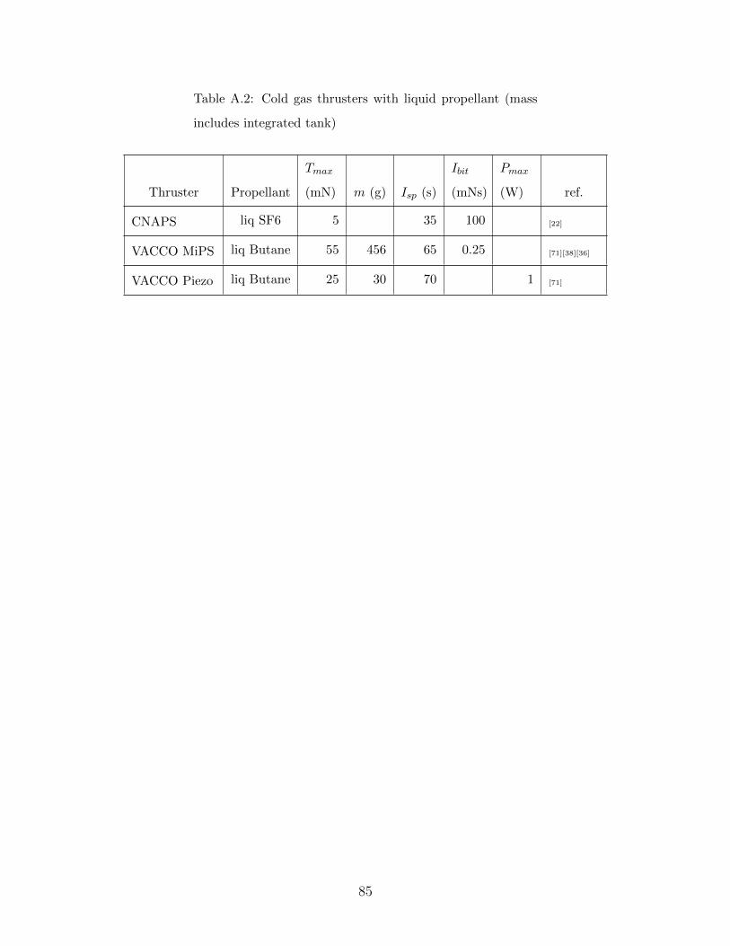
Table A.2: Cold gas thrusters with liquid propellant (mass
includes integrated tank)
Thruster Propellant
Tmax
(mN) m (g) Isp (s)
Ibit
(mNs)
Pmax
(W) ref.
CNAPS liq SF6 5 35 100 [22]
VACCO MiPS liq Butane 55 456 65 0.25 [71][38][36]
VACCO Piezo liq Butane 25 30 70 1 [71]
85

Table A.3: Hydrazine monopropellant thrusters
Thruster
Tmax
(N) m (g)
Isp
(s)
Ibit
(mNs)
Pmax
(W)
Pin
(MPa) ref.
AMPAC
MONARC 11.00000 330 232 11.00 [45][81]
AMPAC
MONARC 55.00000 370 230 90.00 [45][81]
DASA CHT 0.5 0.50000 195 222 7.50 2.20 [116][110][5][1]
DASA CHT 1 1.10000 290 220 10.00 15.90 2.20 [110][5][61]
DASA CHT 10 10.00000 240 225 7.40 2.20 [5][116][110][1]
DASA CHT 2.0 2.00000 210 221 200.00 6.00 [5]
DASA CHT 5 6.00000 220 222 100.00 8.37 2.20 [5][116][110]
DOK-10 10.00000 600 229 [6]
DOT-5 5.00000 900 230 [6]
HmNT 0.12900 40 150 0.05 8.25 [71]
Marquardt KMHS
101.42000 330 226 10.00 [61][70][16]
Marquardt KMHS
174.45000 380 230 2.97 [70][61][16]
MEMS/Yuan
and Li0.00144 162 [71]
µAerospace M005 0.00500 10 150 0.17 0.50 0.35 [94]
µAerospace M010 0.05000 12 160 6.00 0.50 0.35 [94]
µAerospace M050 0.50000 15 170 30.00 1.00 0.35 [94]
µAerospace M100 1.00000 30 200 30.00 2.00 0.35 [94]
Primex 0.10000 220 10.00 [52]
Continued on next page
86

Table A.3 – continued from previous page
Thruster
Tmax
(N) m (g)
Isp
(s)
Ibit
(mNs)
Pmax
(W)
Pin
(MPa) ref.
Primex MR-111C 5.30000 330 228 80.00 13.64 2.76 [116][70][61][45][6]
Primex MR-111E 2.20000 330 219 20.00 13.64 2.55 [70][61][6]
Rafael LT-1N SP 1.10000 250 210 32.00 9.00 2.20 [58]
Rafael LT-5N SP 6.00000 230 200 120.00 9.60 2.20 [116][?]
Redmond MR-103 1.13000 330 215 13.30 14.57 2.83 [70][6][61][103][45][36]
Redmond
MRM-1032.04000 1270 217 30.00 29.14 2.76 [6]
SEP CHT 2 3.50000 460 216 11.20 2.20 [116]
TRW MRE-0.1 1.00000 500 216 17.80 15.00 2.41 [70][17][110]
TRW MRE-1 5.00000 500 218 2.76 [70][61][17]
87

Table A.4: Hydrogen peroxide monopropellant thrusters
Thruster Tmax (N) m (g) Isp (s)
Ibit
(mNs)
Pmax
(W)
Pin
(MPa) ref.
ARC Seibersdorf 0.800 153 [71]
Fotec 0.900 60.0 153 1.5 0.60 [106]
Kuan et al. 0.221 5.8 125 [71]
µAerospace M005HP 0.005 10.0 100 0.12 0.5 0.35 [94]
µAerospace M010HP 0.100 11.0 110 0.90 0.5 0.35 [94]
µAerospace M050HP 0.500 15.0 120 4.00 1.0 0.35 [8][94]
µAerospace M100HP 1.000 20.0 120 8.50 2.0 0.35 [94]
Table A.5: Bipropellant thrusters
Thruster Propellant
Tmax
(N)
m
(g)
Isp
(s)
Pmax
(W)
Mixture
Ratio
Pin
(MPa) ref.
EADS S4 MON/MMH 4.00 290 285 [110][5][116][70]
AMPAC LTT NTO/MMH 9.25 275 [81]
EADS S10 MON/MMH 12.50 350 287 1.64 2.3 [116][70][110][5]
Fotec RP-1/H2O2 3.00 100 320 3 1.2 [106]
LEROS 10 N2O2/MMH 9.50 460 285 [45]
Marquardt
R-2/R-2BNTO/H4N2 4.45 430 280 1.65 [116][70]
Marquardt R-52 MMH/NTO 10.00 295 [70]
Marquardt R-53 12.90 410 295 1.65 [16]
Rocketdyne
RS-45NTO/MMH 4.50 730 300 1.6 [116]
88

Table A.6: Water resistojets
Thruster
Tmax
(mN)
m
(kg)
Isp
(s)
Pmax
(W) η (%)
Pin
(MPa) ref.
Mark IV 50.0 1.500 180 100 0.50 [18]
Marquardt 44.0 220 200 0.25 [52]
MightySat II 75.0 1.240 152 100 1.00 [53][52][59]
Morren @ NASA Lewis 360.0 180 904 2.20 [52]
Othman, Makled 118.0 0.400 140 700 75 [77]
Rocketdyne Technion coupled 122.0 138 505 0.20 [52]
Rocketdyne Technion decoupled 240.0 144 708 0.20 [52]
SSTL Micro Resistojet 3.3 0.013 3 [71][8]
SSTL UoSAT-12 45.0 1.240 152 100 34 [118][1]
89

Table A.7: Hydrazine resistojets
Thruster
Tmax
(mN) m (g)
Isp
(s)
Ibit
(mNs)
Pmax
(W)
Pin
(MPa) ref.
DCA PACT 500 360.0 306 20.00 515 2.20 [118][119]
Redmond 177 300 350 [52][31]
Redmond MR-501B 369 889.0 300 2.20 487 2.41 [52][82][119][118][45][6][36]
Redmond MR-502A 800 870.0 299 88.96 899 2.65 [52][82][118][45][6][36]
Sol Rad-10 10 [85][65]
TRW HiPEHT 490 295 550 [82][118]
TRW 245 226.8 223 4.45 12 1.55 [72]
Table A.8: Ammonia arcjets
Thruster
Tmax
(N) m (g) Isp (s)
Pmax
(kW) η (%) ref.
ESEX Arcjet 2.000 800 26.000 [110][82][6][36]
IRS 600 2.000 [36]
IRS VELARC 0.028 520 0.375 18.5 [1]
IRS VELARC 0.035 350 0.240 25.0 [1]
LeRC Mini LPATS 0.051 360 0.250 36.0 [1]
PSU Microwave 0.300 550 1.100 [52]
U of Stuttgart 0.115 480 480 0.750 [52][120][47]
90

Table A.9: Hydrogen arcjets
Thruster Tmax (N) Isp (s) Pmax (kW) η (%) ref.
HIPARC 3.000 1500 100.000 22 [7]
HIPARC-R 4.000 1400 100.000 28 [7][87]
IRS ESA BMDO 1.364 1300 10.000 40 [36]
IRS VELARC 0.023 865 0.365 26 [1]
IRS VELARC 0.014 820 0.310 18 [1]
Table A.10: Hydrazine arcjets
Thruster
Tmax
(mN) m (kg) Isp (s)
Pmax
(kW)
Pin
(MPa) ref.
BPD/Centrospazio 130 440 1.000 [96]
DCA HAJ1 100 530 0.250 1.80 [118][110]
GE Arcjet 210 1.00 502 1.600 [96]
ISAS SEGAMI-I 176 600 1.500 [96]
OSAKA-IHHI 150 475 1.200 [96]
Redmond MR-507 220 1.50 465 1.400 [118]
Redmond MR-508 230 1.34 502 1.808 1.51 [118][6][?][45]
Redmond MR-509 254 1.48 502 1.808 1.76 [82][6][45]
Redmond MR-510 258 1.58 600 2.000 1.79 [45][6][82][36][102]
Redmond MR-512 254 1.03 502 1.788 1.76 [6]
U of Stuttgart 230 1.30 520 1.200 [96]
91

Table A.11: Ion engines
Thruster
Tmax
(mN)
m
(kg)
Isp
(s)
Pmax
(kW) η (%) ref.
13cm XIPS 17.80 6.50 2507 0.500 68.0 [70][21][96][36][45][108][6][61]
25cm XIPS Hughes 165.00 3500 4.500 65.0 [97][96][45]
25cm XIPS INTELSAT 63.00 9.70 2800 1.300 [21][97][82][36][75][108][51]
ARTEMIS 15.00 1.60 3000 0.600 [96]
CIT 3 cm 0.50 3703 0.024 37.7 [18]
DERA T5 25.00 1.70 3110 0.644 60.0 [82][36][118][108][61]
DERA T6 150.00 6.20 3470 3.900 65.0 [36][118][61]
ETS-6 Kaufman 23.30 3.70 2910 0.600 [20][96]
ETS-8 Kaufman 23.20 2665 0.611 49.7 [20][108]
EURECA 10.00 1.50 3300 0.440 [96]
GRC 8 cm 3.60 1760 0.100 31.0 [18][36]
HiPEP 670.00 46.50 9620 39.300 80.0 [24][25][36]
HiPER DS3G 450.00 10000 25.000 [39]
JPL 31.00 2.50 3200 0.900 66.0 [61][70]
Keldysh Res Center 6.00 3650 0.162 66.0 [61]
Keldysh Res Center 19.00 3500 0.494 65.0 [61]
µ 10 ECR 8.10 2910 0.340 36.0 [76][73][108]
µNRIT-2.5 0.60 0.21 2861 0.034 25.5 [1][71]
MiXI 1.50 0.20 2850 0.050 40.0 [71]
NAL 14 cm 25.00 3500 0.600 [96]
NASA 30cm 178.00 7.00 3610 4.880 67.0 [79]
NASA LeRC 72.00 7.00 2130 1.500 [96]
Continued on next page
92

Table A.11 – continued from previous page
Thruster
Tmax
(mN)
m
(kg)
Isp
(s)
Pmax
(kW) η (%) ref.
NASA Lewis 11.00 2650 0.308 47.0 [61]
NEXIS 470.00 28.70 8500 25.000 78.0 [108][26][24][67][36]
NEXT 238.00 4070 6.860 59.0 [95][36]
NSTAR 92.70 8.20 2500 2.325 61.8 [6][98][61][51][82][36][45][108]
RIT-10 15.00 1.00 3058 0.459 36.0 [5][61][36][1][108][82][118]
RIT-10 EVO 41.00 1.80 3300 1.050 67.0 [5][61][36][70]
RIT-15PL 50.00 3600 1.350 67.0 [61]
RIT-22 250.00 7.00 6400 5.000 [5][36]
RIT-25 25.00 1.75 3060 0.800 67.0 [61][118]
RIT-XT 210.00 4448 6.850 75.5 [5][61]
RMT 12.00 2.00 3600 0.480 55.0 [13][101][61][36]
RUS 5 cm 1.60 2900 0.072 31.6 [18]
SCATHA P78-2 0.14 350 0.045 [6][97][99]
93

Table A.12: Hall Thrusters
Thruster
Tmax
(mN)
m
(kg) Isp (s)
Ibit
(mNs)
Pmax
(kW) η (%) ref.
BHT-1500 102.0 1820 1.700 54.6 [10]
BHT-200 17.0 1.1 1390 2 0.300 32.5 [112][36][71][18]
BHT-20k 1080.0 2750 20.000 70.0 [10][67]
BHT-600-X2B 17.0 0.9 1600 0.600 45.0 [61]
BHT-8000 512.0 20.0 1900 8.000 60.0 [10][15][36]
BHT-HD-1000 55.5 3.5 1700 1.000 56.0 [61]
BHT-HD-600 36.0 2.2 1700 0.600 50.0 [61][36]
D-100 2500 4.500 60.0 [19]
D-100-II 65.0 4250 15.000 65.0 [6][46]
D-20 17.0 2000 0.300 40.0 [19]
D-35 82.0 4.4 1263 1.230 40.0 [61]
D-38 35.0 2000 0.750 45.0 [19][104][61]
D-50 48.0 1700 [6]
D-55 1600 1.400 50.0 [19][82]
DS-HET 300.0 12.0 3000 5.000 50.0 [101]
Fakel SPT-25 6.4 948 0.154 19.0 [18][61][112]
Fakel SPT-35 10.0 1200 0.196 30.0 [1]
HIVHAC 0.4 2500 8.000 62.0 [6][44]
HTX 9.3 1350 0.200 31.0 [112]
IT-100 18.0 3100 0.500 50.0 [46]
IT-50 5.0 2900 0.140 55.0 [46]
Jacobson, Jankovsky 1.0 3250 25.000 60.0 [87]
Continued on next page
94

Table A.12 – continued from previous page
Thruster
Tmax
(mN)
m
(kg) Isp (s)
Ibit
(mNs)
Pmax
(kW) η (%) ref.
Keldysh K-15 16.0 1718 0.400 36.0 [61]
Keldysh KM-32 10.4 1410 0.156 45.0 [61]
Keldysh KM-37 18.4 1635 0.294 49.0 [61]
Keldysh X-40 35.0 1750 0.525 56.0 [61]
KeRC 5.7 895 0.109 22.9 [18]
KM-20 8.8 1850 0.210 39.0 [112]
MHT-9 16.6 1676 0.481 29.0 [112]
MIT 50W 1.8 865 0.126 6.0 [71][112]
Moskow SPT-30 13.0 0.4 1170 0.260 30.0 [61][112]
NASA Glenn 1.0 0.500 [40]
NASA Glenn 2.5 1.000 [40]
NASA Glenn 2.5 1.500 [40]
NASA Glenn 3.0 2.000 [40]
NASA Glenn 4.3 2.000 [40]
NASA Glenn 5.5 4.500 [40]
NASA Glenn 6.5 5.000 [40]
NASA Glenn 7.0 5.000 [40]
NASA Glenn 8.0 5.500 [40]
NASA Glenn 12.0 8.000 [40]
NASA Glenn 12.0 10.000 [40]
NASA Glenn 12.0 11.000 [40]
NASA Glenn 20.0 15.500 [40]
Continued on next page
95

Table A.12 – continued from previous page
Thruster
Tmax
(mN)
m
(kg) Isp (s)
Ibit
(mNs)
Pmax
(kW) η (%) ref.
NASA Glenn 18.0 16.500 [40]
NASA-137Mv2 342.0 3000 7.872 59.6 [33]
NASA-300M 1130.0 2640 20.000 67.0 [67][41]
NASA-457M 2900.0 80.0 2900 75.000 56.0 [67][6][87][41]
NASA-457Mv2 1280.0 2520 25.200 63.0 [41]
P5 246.0 2326 5.000 [6]
PPl Annul 3.5 1086 0.098 19.0 [18]
PPl Cylind 3.7 1136 0.103 20.0 [18]
PPPL CHT 2.6 12.0 0.300 23.5 [71]
PPPL CHT 3.0 6.0 1325 0.185 23.5 [71]
PPS 1350-G 90.0 4.5 1650 1.500 45.0 [19][61][108][93]
PPS-20k ML 1050.0 25.0 2500 22.400 60.0 [121][46][67]
PPSX000 340.0 2480 6.000 [82][36]
Princeton 54.4 1550 0.870 46.0 [61]
Redmond BPT-2000 0.1 5.2 1765 2.200 48.0 [6]
Redmond BPT-4000 0.3 7.5 1950 4.500 58.0 [6]
SPT-100 100.0 3.5 1600 1.400 50.0[4][19][61][82]
[36][45][108]
SPT-140 300.0 1750 5.000 55.0 [108]
SPT-160 400.0 2500 4.500 60.0 [19]
SPT-200 498.0 2250 11.000 63.0 [40]
SPT-290 1500.0 23.0 3300 30.000 70.0 [40][67][15]
SPT-30 13.0 1.0 973 0.258 25.0 [71]
Continued on next page
96
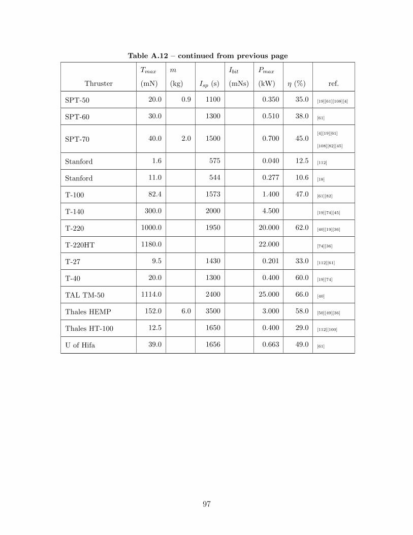
Table A.12 – continued from previous page
Thruster
Tmax
(mN)
m
(kg) Isp (s)
Ibit
(mNs)
Pmax
(kW) η (%) ref.
SPT-50 20.0 0.9 1100 0.350 35.0 [19][61][108][4]
SPT-60 30.0 1300 0.510 38.0 [61]
SPT-70 40.0 2.0 1500 0.700 45.0[4][19][61]
[108][82][45]
Stanford 1.6 575 0.040 12.5 [112]
Stanford 11.0 544 0.277 10.6 [18]
T-100 82.4 1573 1.400 47.0 [61][82]
T-140 300.0 2000 4.500 [19][74][45]
T-220 1000.0 1950 20.000 62.0 [40][19][36]
T-220HT 1180.0 22.000 [74][36]
T-27 9.5 1430 0.201 33.0 [112][61]
T-40 20.0 1300 0.400 60.0 [19][74]
TAL TM-50 1114.0 2400 25.000 66.0 [40]
Thales HEMP 152.0 6.0 3500 3.000 58.0 [50][49][36]
Thales HT-100 12.5 1650 0.400 29.0 [112][100]
U of Hifa 39.0 1656 0.663 49.0 [61]
97

Table A.13: Pulsed plasma thrusters
Thruster
Tmax
(mN)
m
(kg)
Isp
(s)
Ibit
(µNs)
Pmax
(W) η (%) ref.
37 min parabolic 2.800 280 2.30 [68]
Academy Sinica
Geom-Varying445 133.00 4.00 [68]
advPPT 4.200 515 133.0 8.00 [61]
AFRL 0.030 2.00 20.0 [71]
APPT 5.200 1700 650.00 250.0 17.00 [68][61]
ARCS 0.025 2.00 4.0 [71]
ASU 1616 490.00 10.50 [68]
Busek µPPT 827 80.00 10.0 [11]
China Lab 990 448.00 [83]
CSSAR 40J 1188 605.00 9.00 [68]
CU UI PPT-11 1400 100.0 15.00 [36]
CU UI PPT-8 360 533.00 4.00 [68]
Dawgstar 0.112 1.720 483 56.10 10.2 1.80 [114][9][68][71][113]
ETS-IV (Japanese) 0.029 6.600 300 2.2 1.92 [9][68]
Fairchild, NASA 808 6640.00 10.00 [68]
FalconSat-3 1.700 827 8.40 [113][11][68]
FOTEC µPPT 0.010 500 10.00 2.0 [106]
IIT, U Singapore
self-ignited1600 30.00 6.00 [68]
IL PPT-3 Lab 600 450.00 [83]
IRS ADD-Simplex 1.370 2620 1200.00 68.0 14.00 [1][68]
Continued on next page
98
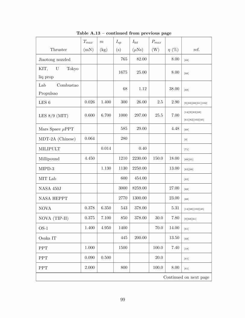
Table A.13 – continued from previous page
Thruster
Tmax
(mN)
m
(kg)
Isp
(s)
Ibit
(µNs)
Pmax
(W) η (%) ref.
Jiaotong nozzled 765 82.00 8.00 [68]
KIT, U Tokyo
liq prop1675 25.00 8.00 [68]
Lab Combustao
Propulsao68 1.12 38.00 [68]
LES 6 0.026 1.400 300 26.00 2.5 2.90 [9][83][68][61][102]
LES 8/9 (MIT) 0.600 6.700 1000 297.00 25.5 7.00[14][9][83][68]
[61][82][102][45]
Mars Space µPPT 585 29.00 4.48 [68]
MDT-2A (Chinese) 0.064 280 [9]
MILIPULT 0.014 0.40 [71]
Millipound 4.450 1210 2230.00 150.0 18.00 [68][61]
MIPD-3 1.130 1130 2250.00 13.00 [83][68]
MIT Lab 600 454.00 [83]
NASA 450J 3000 8259.00 27.00 [68]
NASA HEPPT 2770 1300.00 23.00 [68]
NOVA 0.378 6.350 543 378.00 5.31 [14][68][102][45]
NOVA (TIP-II) 0.375 7.100 850 378.00 30.0 7.80 [9][68][61]
OS-1 1.400 4.950 1400 70.0 14.00 [61]
Osaka IT 445 200.00 13.50 [68]
PPT 1.000 1500 100.0 7.40 [18]
PPT 0.090 0.500 20.0 [61]
PPT 2.000 800 100.0 8.00 [61]
Continued on next page
99
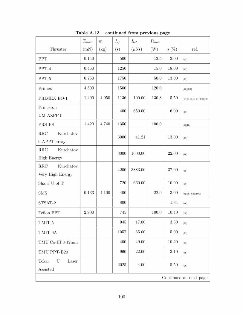
Table A.13 – continued from previous page
Thruster
Tmax
(mN)
m
(kg)
Isp
(s)
Ibit
(µNs)
Pmax
(W) η (%) ref.
PPT 0.140 500 12.5 3.00 [61]
PPT-4 0.450 1250 15.0 18.00 [61]
PPT-5 0.750 1750 50.0 13.00 [61]
Primex 4.500 1500 120.0 [52][82]
PRIMEX EO-1 1.400 4.950 1136 100.00 130.8 5.50 [14][113][114][83][68]
Princeton
UM AZPPT400 650.00 6.00 [68]
PRS-101 1.420 4.740 1350 100.0 [6][45]
RRC Kurchatov
9-APPT array3000 41.21 13.00 [68]
RRC Kurchatov
High Energy3000 1600.00 22.00 [68]
RRC Kurchatov
Very High Energy4200 3883.00 37.00 [68]
Shairf U of T 720 660.00 10.00 [68]
SMS 0.133 4.100 400 22.0 3.00 [9][68][61][102]
STSAT-2 800 1.34 [68]
Teflon PPT 2.900 745 100.0 10.40 [18]
TMIT-5 945 17.00 3.30 [68]
TMIT-6A 1057 35.00 5.00 [68]
TMU Co-III 3-12mm 400 49.00 10.20 [68]
TMU PPT-B20 960 22.00 3.10 [68]
Tokai U Laser
Assisted2025 4.00 5.50 [68]
Continued on next page
100

Table A.13 – continued from previous page
Thruster
Tmax
(mN)
m
(kg)
Isp
(s)
Ibit
(µNs)
Pmax
(W) η (%) ref.
U Tokyo External B 423 469.00 3.00 [83][68]
UCV XPPT-8 1210 320.00 9.00 [68]
UI PPT 3,4,5 2200 150.00 19.50 [68]
Zond 2 2.000 5.000 410 50.0 8.04 [9][68][61]
Table A.14: Vacuum arc thrusters
Thruster
Tmax
(mN) m (kg) Isp (s)
Ibit
(µNs)
Pmax
(W) η (%) ref.
AASC VAT (ION) 1.000 100 2000 0.25 100 [36][32][71][89]
AASC MVAT 0.125 150 2000 100 10.00 [36][8][84][107]
Lun 56.000 500 160 10 0.05 [60]
MPNL CT 10.000 140 3500 0.10 2 14.00 [43][42]
101

Table A.15: Field emission electric propulsion
Thruster Propellant
Tmax
(mN)
m
(kg)
Isp
(s)
Ibit
(nNs)
Pmax
(W)
η
(%) ref.
Alta FEEP-100 Cs 0.120 10000 7.2 82 [61]
Alta FEEP-150 Cs 0.300 1.41 9000 20.0 90 [3][78]
Alta FEEP-1000 Cs 1.200 5.00 10000 72.0 82 [61]
ARCS GOCE MTA In 0.650 12000 80.0 [71]
ARCS InFEEP-100 In 0.100 12000 10.0 [61][71]
ARCS
InFEEP-1000In 1.000 12000 80.0 [36][71]
ARCS inFEEP-25 In 0.025 7.10 10000 [61][36]
Centrospazio Cs 0.800 3.50 8000 60.0 [70]
Centrospazio Cs 0.100 0.45 8000 9.0 [70]
Centrospazio FEEP Cs 1.000 6000 60.0 [52]
Centrospazio
FEEP-5Cs 0.040 0.60 9000 2.7 65 [61][71]
Centrospazio
FEEP-50Cs 1.400 1.20 9000 93.0
[61][71]
[86]
FEEP In 0.100 2.50 10000 10 6.7 [54]
FOTEC mN-FEEP In or Ga 0.300 0.30 4000 5 7.0 50 [106]
FOTEC
Single FEEPIn 0.015 0.08 5000 5 0.5 50 [106]
InFEEP In 0.120 12000 95 [64]
In-FEEP In 0.100 2.50 8000 5 13.0 95 [105]
Slit Emitter FEEP Cs 1.200 2.20 9000 1 [54]
102
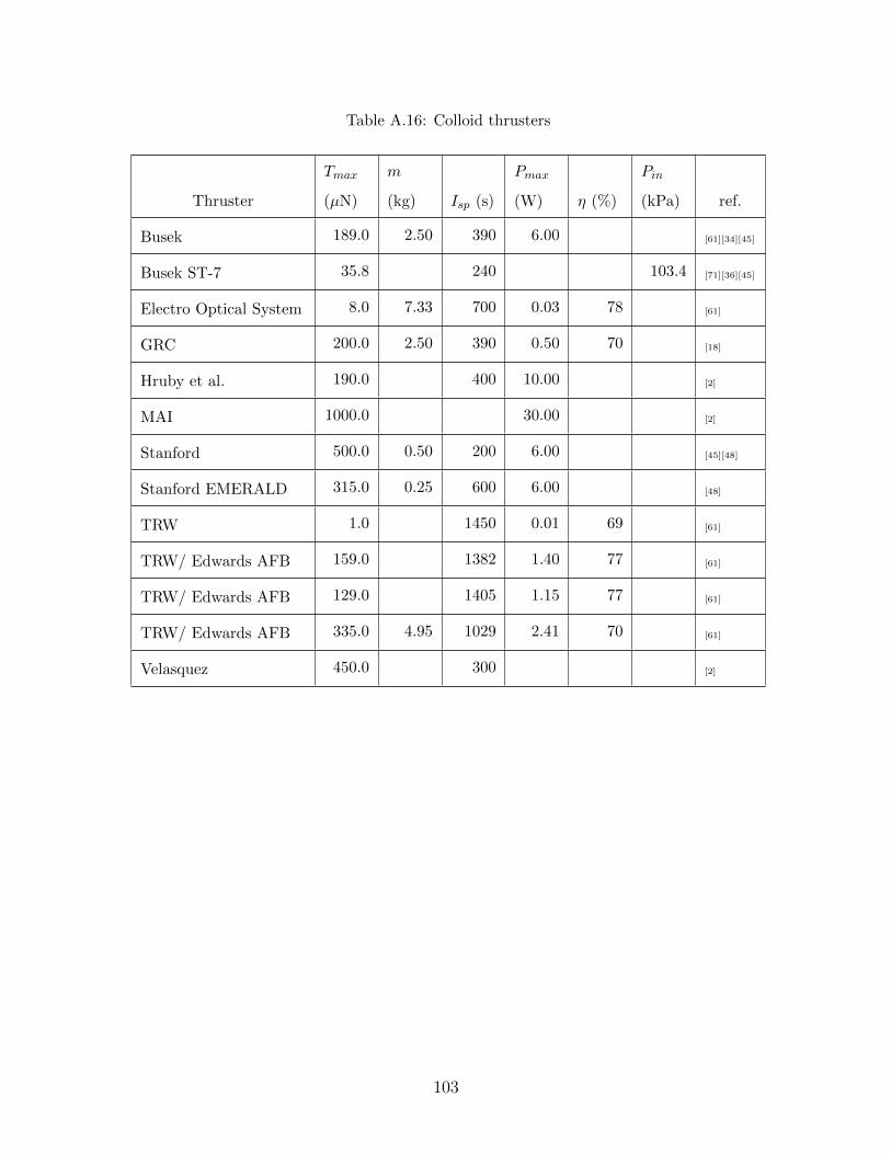
Table A.16: Colloid thrusters
Thruster
Tmax
(µN)
m
(kg) Isp (s)
Pmax
(W) η (%)
Pin
(kPa) ref.
Busek 189.0 2.50 390 6.00 [61][34][45]
Busek ST-7 35.8 240 103.4 [71][36][45]
Electro Optical System 8.0 7.33 700 0.03 78 [61]
GRC 200.0 2.50 390 0.50 70 [18]
Hruby et al. 190.0 400 10.00 [2]
MAI 1000.0 30.00 [2]
Stanford 500.0 0.50 200 6.00 [45][48]
Stanford EMERALD 315.0 0.25 600 6.00 [48]
TRW 1.0 1450 0.01 69 [61]
TRW/ Edwards AFB 159.0 1382 1.40 77 [61]
TRW/ Edwards AFB 129.0 1405 1.15 77 [61]
TRW/ Edwards AFB 335.0 4.95 1029 2.41 70 [61]
Velasquez 450.0 300 [2]
103

104

Appendix B
Source Code
1 function [propellant mass fraction, propulsion mass fraction, ...
inert mass, propellant mass, ...
max power]=thruster mass(deltaV,total initial mass,max acceleration, ...
thruster type)
2
3 %%%%%%%%%%%%%%%%%%%%%%%%%%%%%%%%%%%%%%%%%%%%%%%%%%%%%%%%%%%%%%%%%%%%%%%%%%%
4 %
5 % Filename: thruster mass.m
6 % Filetype: Function
7 % Project: F6
8 % Author: Thomas Chiasson
9 % Mod Date: 19/8/2011
10 %
11 % PURPOSE: Estimates the mass of a propulsion system.
12 %
13 % USAGE: This is the main program called for propulsion system
14 % estimation. It can be used stand−alone or called within
15 % another program. The equations formed from the database are
16 % hardcoded and propellant and tank constants are read from
17 % the database, 'thrustertradespace.xlx'. All other constants
18 % and equations are in this program, with programs for tank
19 % optimization called from within this code.
105
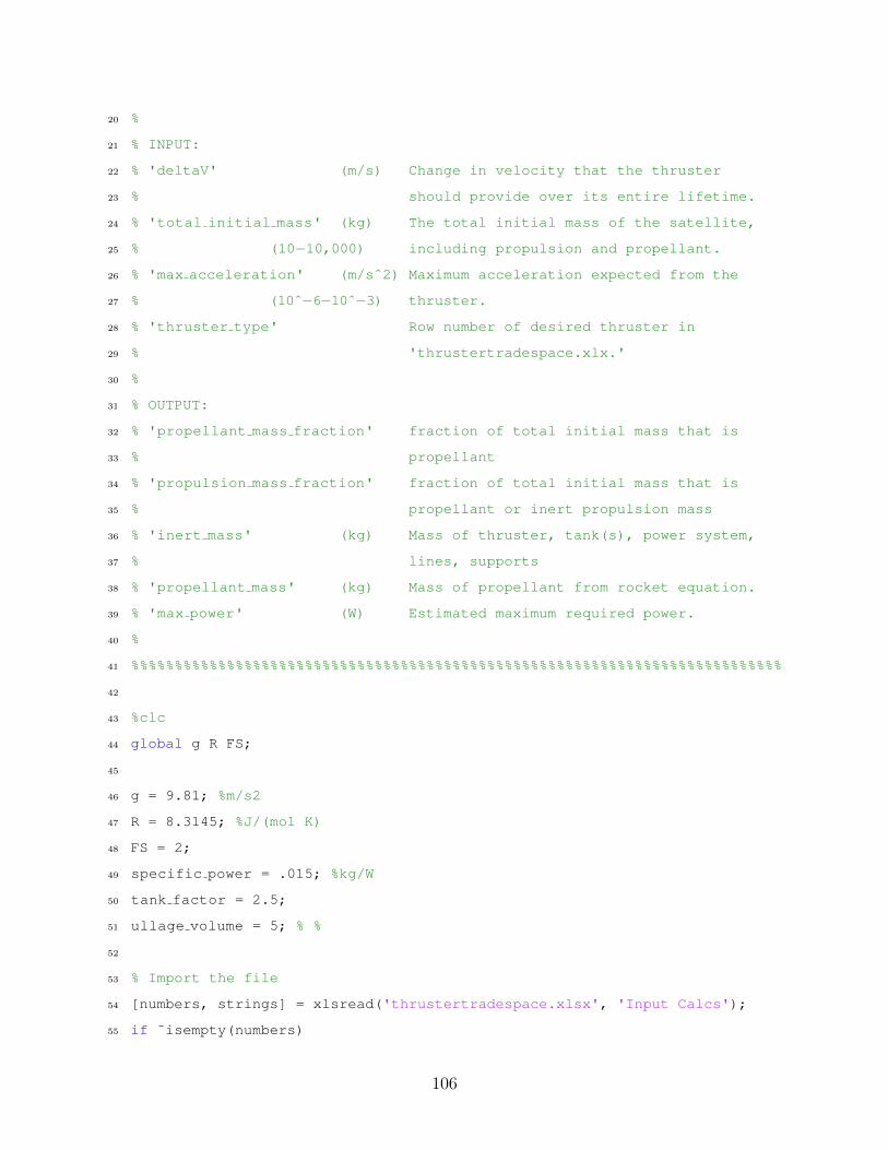
20 %
21 % INPUT:
22 % 'deltaV' (m/s) Change in velocity that the thruster
23 % should provide over its entire lifetime.
24 % 'total initial mass' (kg) The total initial mass of the satellite,
25 % (10−10,000) including propulsion and propellant.
26 % 'max acceleration' (m/sˆ2) Maximum acceleration expected from the
27 % (10ˆ−6−10ˆ−3) thruster.
28 % 'thruster type' Row number of desired thruster in
29 % 'thrustertradespace.xlx.'
30 %
31 % OUTPUT:
32 % 'propellant mass fraction' fraction of total initial mass that is
33 % propellant
34 % 'propulsion mass fraction' fraction of total initial mass that is
35 % propellant or inert propulsion mass
36 % 'inert mass' (kg) Mass of thruster, tank(s), power system,
37 % lines, supports
38 % 'propellant mass' (kg) Mass of propellant from rocket equation.
39 % 'max power' (W) Estimated maximum required power.
40 %
41 %%%%%%%%%%%%%%%%%%%%%%%%%%%%%%%%%%%%%%%%%%%%%%%%%%%%%%%%%%%%%%%%%%%%%%%%%%%
42
43 %clc
44 global g R FS;
45
46 g = 9.81; %m/s2
47 R = 8.3145; %J/(mol K)
48 FS = 2;
49 specific power = .015; %kg/W
50 tank factor = 2.5;
51 ullage volume = 5; % %
52
53 % Import the file
54 [numbers, strings] = xlsread('thrustertradespace.xlsx', 'Input Calcs');
55 if ˜isempty(numbers)
106
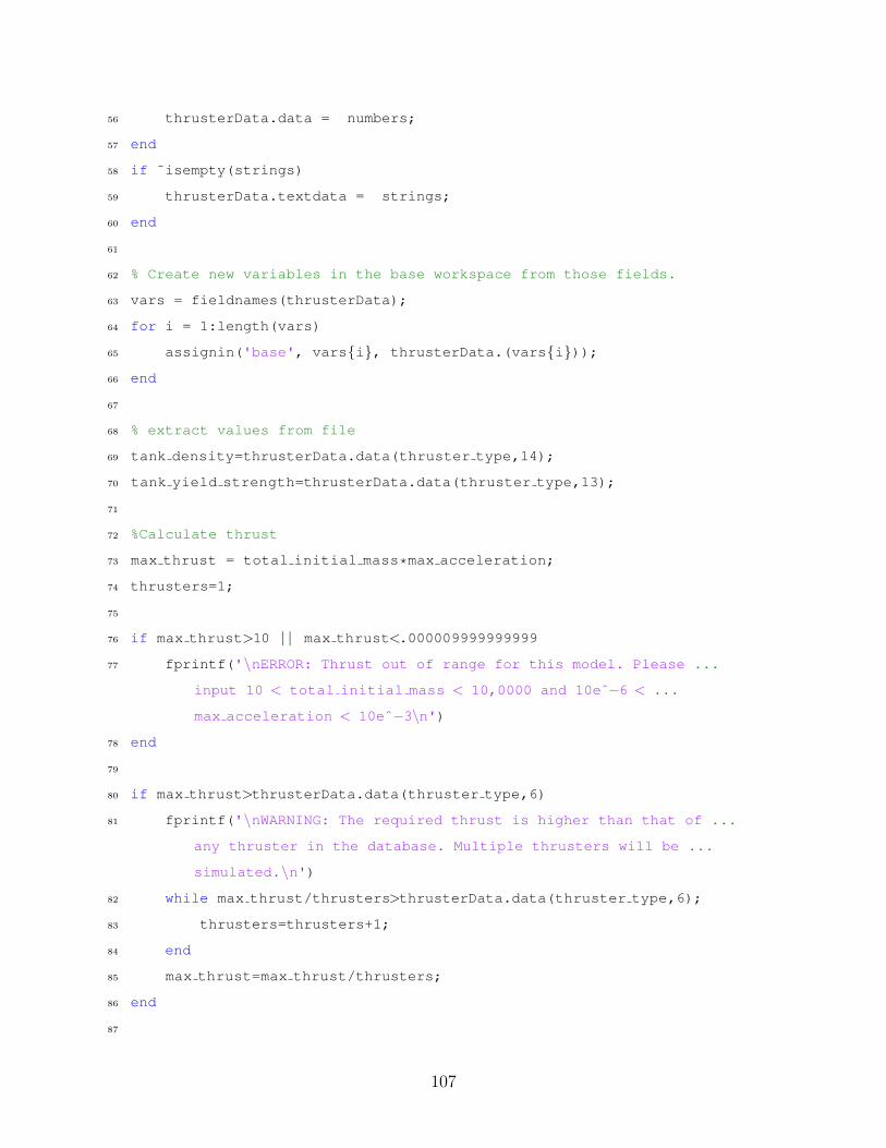
56 thrusterData.data = numbers;
57 end
58 if ˜isempty(strings)
59 thrusterData.textdata = strings;
60 end
61
62 % Create new variables in the base workspace from those fields.
63 vars = fieldnames(thrusterData);
64 for i = 1:length(vars)
65 assignin('base', vars{i}, thrusterData.(vars{i}));
66 end
67
68 % extract values from file
69 tank density=thrusterData.data(thruster type,14);
70 tank yield strength=thrusterData.data(thruster type,13);
71
72 %Calculate thrust
73 max thrust = total initial mass*max acceleration;
74 thrusters=1;
75
76 if max thrust>10 | | max thrust<.000009999999999
77 fprintf('\nERROR: Thrust out of range for this model. Please ...
input 10 < total initial mass < 10,0000 and 10eˆ−6 < ...
max acceleration < 10eˆ−3\n')
78 end
79
80 if max thrust>thrusterData.data(thruster type,6)
81 fprintf('\nWARNING: The required thrust is higher than that of ...
any thruster in the database. Multiple thrusters will be ...
simulated.\n')
82 while max thrust/thrusters>thrusterData.data(thruster type,6);
83 thrusters=thrusters+1;
84 end
85 max thrust=max thrust/thrusters;
86 end
87
107

88 if max thrust<thrusterData.data(thruster type,4)
89 fprintf('\nWARNING: The required thrust is lower than that of ...
any thruster in the database. Thrust is being raised to that ...
of the lowest thrust model in the database: %i N\n', ...
thrusterData.data(thruster type,4))
90 max thrust = thrusterData.data(thruster type,4);
91 end
92
93
94 %Calculate specs and masses (see thrustertradespace.xls for equations)
95 switch thruster type
96
97 case 1 %Nitrogen Cold gas thruster
98 exhaust velocity = thrusterData.data(thruster type,7)*g;
99 max power = 11.607*max thrustˆ0.2294;
100 thruster mass = thrusterData.data(thruster type,10);
101
102 %Calculate propellant mass
103 propellant mass=total initial mass.*(1−exp(−deltaV./exhaust velocity));
104
105 %Calculate tank mass
106 if max thrust<=.12
107 propellant pressure=88030*log(max thrust)+741342;
108 else
109 propellant pressure=3165825;
110 end
111 propellant temperature=thrusterData.data(thruster type,16);
112 propellant molar mass=thrusterData.data(thruster type,15);
113 initial propellant mass = ...
fminsearch(@(initial propellant mass) ...
cold tank mass(initial propellant mass, propellant mass, ...
propellant temperature, propellant molar mass, ...
propellant pressure, tank yield strength, ...
tank density),propellant mass);
114 tank mass=tank factor*cold tank mass(initial propellant mass, ...
propellant mass, propellant temperature, ...
108

propellant molar mass, propellant pressure, ...
tank yield strength, tank density);
115
116 if initial propellant mass < propellant mass
117 fprintf('\nERROR: tank optimization incorrect\n')
118 thruster type
119 deltaV
120 total initial mass
121 max acceleration
122 end
123
124 %syms m0 real;
125 %simplify(estimate tank mass(m0, propellant mass, ...
propellant temperature, propellant molar mass, ...
propellant pressure, tank yield strength, tank density))
126 %ezplot(cold tank mass(m0, propellant mass, ...
propellant temperature, propellant molar mass, ...
propellant pressure, tank yield strength, ...
tank density),[propellant mass,propellant mass*1.3])
127
128 case 2 %Helium Cold gas thruster
129 exhaust velocity = thrusterData.data(thruster type,7)*g;
130 max power = 11.607*max thrustˆ0.2294;
131 thruster mass = thrusterData.data(thruster type,10);
132
133 %Calculate propellant mass
134 propellant mass=total initial mass.*(1−exp(−deltaV./exhaust velocity));
135
136 %Calculate tank mass
137 if max thrust<=.12
138 propellant pressure=88030*log(max thrust)+741342;
139 else
140 propellant pressure=3165825;
141 end
142 propellant temperature=thrusterData.data(thruster type,16);
143 propellant molar mass=thrusterData.data(thruster type,15);
109

144 initial propellant mass = ...
fminsearch(@(initial propellant mass) ...
cold tank mass(initial propellant mass, propellant mass, ...
propellant temperature, propellant molar mass, ...
propellant pressure, tank yield strength, ...
tank density),propellant mass);
145 tank mass=tank factor*cold tank mass(initial propellant mass, ...
propellant mass, propellant temperature, ...
propellant molar mass, propellant pressure, ...
tank yield strength, tank density);
146
147 if initial propellant mass < propellant mass
148 fprintf('\nERROR: tank optimization incorrect\n')
149 thruster type
150 deltaV
151 total initial mass
152 max acceleration
153 end
154
155 %syms m0 real;
156 %simplify(estimate tank mass(m0, propellant mass, ...
propellant temperature, propellant molar mass, ...
propellant pressure, tank yield strength, tank density))
157 %ezplot(cold tank mass(m0, propellant mass, ...
propellant temperature, propellant molar mass, ...
propellant pressure, tank yield strength, ...
tank density),[propellant mass*.7,propellant mass*1.3])
158
159 case 3 %Butane Cold gas thruster
160 exhaust velocity = thrusterData.data(thruster type,7)*g;
161 max power = thrusterData.data(thruster type,9);
162 thruster mass = thrusterData.data(thruster type,10);
163
164 %Calculate propellant mass
165 propellant mass=total initial mass.*(1−exp(−deltaV./exhaust velocity));
166 if propellant mass/thrusters > .053
110

167 fprintf('\nWARNING: This thruster is integrated with its ...
propellant tank and the required deltaV is higher ...
than what can be provided. Multiple thrusters will ...
be simulated.')
168 while propellant mass/thrusters > .053
169 thrusters=thrusters+1;
170 end
171 end
172
173 %tank mass included in thruster mass
174 tank mass=0;
175
176 case 4 %Hydrazine Monopropellant thruster
177 exhaust velocity = 206.21*max thrustˆ0.048*g;
178 thruster mass = 0.161*max thrustˆ0.5778;
179 max power = 28.684*thruster massˆ0.7943;
180
181 %Calculate propellant mass
182 propellant mass=total initial mass.*(1−exp(−deltaV./exhaust velocity));
183
184 %Calculate propellant tank mass
185 propellant pressure=2558.7*exp(0.0311*exhaust velocity/g);
186 propellant tank volume=(1+ullage volume/100)*propellant mass/...
187 thrusterData.data(thruster type,12);
188 tank radius=(propellant tank volume./(4/3*pi)).ˆ(1/3);
189 tank thickness=propellant pressure.*tank radius*FS/tank yield strength/2;
190 propellant tank mass=tank factor*4/3*pi*((tank radius+...
191 tank thickness).ˆ3−tank radius.ˆ3).*tank density;
192
193 %Calculate pressurant tank mass
194 pressurant temperature=thrusterData.data(1,16);
195 pressurant molar mass=thrusterData.data(1,15); % use N2 gas ...
as pressurant
196 pressurant tank density=thrusterData.data(1,14);
197 pressurant tank yield strength=thrusterData.data(1,13); % ...
use Ti alloy as tank material
111

198
199 %syms V0 real
200 %pretty(simplify(mono tank mass(m0, pressurant temperature, ...
pressurant molar mass, propellant pressure, ...
propellant tank volume, pressurant tank yield strength, ...
pressurant tank density)))
201 %ezplot(mono tank mass(V0, pressurant temperature, ...
pressurant molar mass, propellant pressure, ...
propellant tank volume, pressurant tank yield strength, ...
pressurant tank density),[0,propellant tank volume*.2])
202
203 pressurant tank volume = ...
fminsearch(@(pressurant tank volume) ...
mono tank mass(pressurant tank volume, ...
pressurant temperature, pressurant molar mass, ...
propellant pressure, propellant tank volume, ...
pressurant tank yield strength, pressurant tank density),0);
204 pressurant tank mass = ...
tank factor*mono tank mass(pressurant tank volume, ...
pressurant temperature, pressurant molar mass, ...
propellant pressure, propellant tank volume, ...
pressurant tank yield strength, pressurant tank density);
205
206 %initial pressurant volume = ...
fminsearch(@(initial pressurant volume) ...
mono tank mass2(initial pressurant volume, ...
pressurant temperature, pressurant molar mass, ...
propellant pressure, propellant tank volume, ...
tank yield strength, ...
tank density),propellant tank volume*.1)
207 %tank mass = mono tank mass2(initial pressurant volume, ...
pressurant temperature, pressurant molar mass, ...
propellant pressure, propellant tank volume, ...
tank yield strength, tank density)
208
209 if pressurant tank volume < 0
112

210 fprintf('\nERROR: tank optimization incorrect\n')
211 thruster type
212 deltaV
213 total initial mass
214 max acceleration
215 end
216
217 %propellant mass
218 %propellant tank volume
219 %propellant tank mass
220 %pressurant tank volume
221 %pressurant tank mass
222
223 tank mass=propellant tank mass+pressurant tank mass;
224
225 case 5 %Hydrogen peroxide Monopropellant thruster
226 exhaust velocity = 136.76*max thrustˆ0.0649*g;
227 thruster mass = 0.0077*exp(1.4637*max thrust);
228 max power = 0.4715*exp(1.3858*max thrust);
229
230 %Calculate propellant mass
231 propellant mass=total initial mass.*(1−exp(−deltaV./exhaust velocity));
232
233 %Calculate propellant tank mass
234 propellant pressure=103421*exp(0.011*exhaust velocity/g);
235 propellant tank volume=(1+ullage volume/100)*propellant mass/...
236 thrusterData.data(thruster type,12);
237 tank radius=(propellant tank volume./(4/3*pi)).ˆ(1/3);
238 tank thickness=propellant pressure.*tank radius*FS/tank yield strength/2;
239 propellant tank mass=tank factor*4/3*pi*((tank radius+...
240 tank thickness).ˆ3−tank radius.ˆ3).*tank density;
241
242 %Calculate pressurant tank mass
243 pressurant temperature=thrusterData.data(1,16);
244 pressurant molar mass=thrusterData.data(1,15); % use N2 gas ...
as pressurant
113
245 pressurant tank density=thrusterData.data(1,14);
246 pressurant tank yield strength=thrusterData.data(1,13); % ...
use Ti alloy as tank material
247
248 %syms V0 real
249 %pretty(simplify(mono tank mass(m0, pressurant temperature, ...
pressurant molar mass, propellant pressure, ...
propellant tank volume, pressurant tank yield strength, ...
pressurant tank density)))
250 %ezplot(mono tank mass(V0, pressurant temperature, ...
pressurant molar mass, propellant pressure, ...
propellant tank volume, pressurant tank yield strength, ...
pressurant tank density),[0,propellant tank volume*.2])
251
252 pressurant tank volume = ...
fminsearch(@(pressurant tank volume) ...
mono tank mass(pressurant tank volume, ...
pressurant temperature, pressurant molar mass, ...
propellant pressure, propellant tank volume, ...
pressurant tank yield strength, pressurant tank density),0);
253 pressurant tank mass = ...
tank factor*mono tank mass(pressurant tank volume, ...
pressurant temperature, pressurant molar mass, ...
propellant pressure, propellant tank volume, ...
pressurant tank yield strength, pressurant tank density);
254
255 %initial pressurant volume = ...
fminsearch(@(initial pressurant volume) ...
mono tank mass2(initial pressurant volume, ...
pressurant temperature, pressurant molar mass, ...
propellant pressure, propellant tank volume, ...
tank yield strength, ...
tank density),propellant tank volume*.1)
256 %tank mass = mono tank mass2(initial pressurant volume, ...
pressurant temperature, pressurant molar mass, ...
propellant pressure, propellant tank volume, ...
114

tank yield strength, tank density)
257
258 if pressurant tank volume < 0
259 fprintf('\nERROR: tank optimization incorrect\n')
260 thruster type
261 deltaV
262 total initial mass
263 max acceleration
264 end
265
266 %propellant mass
267 %propellant tank volume
268 %propellant tank mass
269 %pressurant tank volume
270 %pressurant tank mass
271
272 tank mass=propellant tank mass+pressurant tank mass;
273
274 case 6 %Nitrogen tetroxide monomethylhydrazine bipropellant thruster
275 exhaust velocity = thrusterData.data(thruster type,7)*g;
276 max power = thrusterData.data(thruster type,9);
277 thruster mass = thrusterData.data(thruster type,10);
278
279 %Calculate propellant masses
280 oxidizer fuel ratio = 1.65;
281 propellant mass=total initial mass.*(1−exp(−deltaV./exhaust velocity));
282 fuel mass=propellant mass/(1+oxidizer fuel ratio);
283 oxidizer mass=propellant mass−fuel mass;
284 propellant pressure=thrusterData.data(thruster type,11);
285
286 %Calculate fuel tank mass
287 fuel density = 878; %kg/m3 (MMH)
288 fuel tank volume=(1+ullage volume/100)*fuel mass/fuel density;
289 fuel tank radius=(fuel tank volume./(4/3*pi)).ˆ(1/3);
290 fuel tank thickness=propellant pressure.*fuel tank radius*FS/...
291 tank yield strength/2;
115

292 fuel tank mass=tank factor*4/3*pi*((fuel tank radius+...
293 fuel tank thickness).ˆ3−fuel tank radius.ˆ3).*tank density;
294
295 %Calculate oxidizer tank mass
296 oxidizer density = 1440; %kg/m3 (NTO)
297 oxidizer tank volume=(1+ullage volume/100)*oxidizer mass/oxidizer density;
298 oxidizer tank radius=(oxidizer tank volume./(4/3*pi)).ˆ(1/3);
299 oxidizer tank thickness=propellant pressure.*oxidizer tank radius...
300 *FS/tank yield strength/2;
301 oxidizer tank mass=tank factor*tank factor*4/3*pi*((...
302 oxidizer tank radius+oxidizer tank thickness).ˆ3−...
303 oxidizer tank radius.ˆ3).*tank density;
304
305 %Calculate pressurant tank mass
306 pressurant temperature=thrusterData.data(1,16);
307 pressurant molar mass=thrusterData.data(1,15); % use N2 gas ...
as pressurant
308 pressurant tank density=thrusterData.data(1,14);
309 pressurant tank yield strength=thrusterData.data(1,13); % ...
use Ti alloy as tank material
310
311 %syms V0 real
312 %pretty(simplify(mono tank mass(m0, pressurant temperature, ...
pressurant molar mass, propellant pressure, ...
propellant tank volume, pressurant tank yield strength, ...
pressurant tank density)))
313 %ezplot(mono tank mass(V0, pressurant temperature, ...
pressurant molar mass, propellant pressure, ...
fuel tank volume+oxidizer tank volume, ...
pressurant tank yield strength, ...
pressurant tank density),[0,(fuel tank volume+oxidizer tank volume)*.2])
314
315 pressurant tank volume = ...
fminsearch(@(pressurant tank volume) ...
mono tank mass(pressurant tank volume, ...
pressurant temperature, pressurant molar mass, ...
116
propellant pressure, ...
fuel tank volume+oxidizer tank volume, ...
pressurant tank yield strength, pressurant tank density),0);
316 pressurant tank mass = ...
tank factor*mono tank mass(pressurant tank volume, ...
pressurant temperature, pressurant molar mass, ...
propellant pressure, ...
fuel tank volume+oxidizer tank volume, ...
pressurant tank yield strength, pressurant tank density);
317
318 %initial pressurant volume = ...
fminsearch(@(initial pressurant volume) ...
mono tank mass2(initial pressurant volume, ...
pressurant temperature, pressurant molar mass, ...
propellant pressure, propellant tank volume, ...
tank yield strength, ...
tank density),propellant tank volume*.1)
319 %tank mass = mono tank mass2(initial pressurant volume, ...
pressurant temperature, pressurant molar mass, ...
propellant pressure, propellant tank volume, ...
tank yield strength, tank density)
320
321 if pressurant tank volume < 0
322 fprintf('\nERROR: tank optimization incorrect\n')
323 thruster type
324 deltaV
325 total initial mass
326 max acceleration
327 end
328
329 %propellant mass
330 %fuel mass
331 %fuel tank volume
332 %fuel tank mass
333 %oxidizer mass
334 %oxidizer tank volume
117

335 %oxidizer tank mass
336 %pressurant tank volume
337 %pressurant tank mass
338
339 tank mass=fuel tank mass+oxidizer tank mass+pressurant tank mass;
340
341 case 7 %Water Resistojet
342 exhaust velocity = thrusterData.data(thruster type,7)*g;
343 max power = 5156.5*max thrustˆ1.2627;
344 thruster mass = 0.0149*max powerˆ0.7736;
345
346 %Calculate propellant mass
347 propellant mass=total initial mass.*(1−exp(−deltaV./exhaust velocity));
348
349 %Calculate propellant tank mass
350 propellant pressure=4E6*max thrust + 112214;
351 propellant tank volume=(1+ullage volume/100)*propellant mass/...
352 thrusterData.data(thruster type,12);
353 tank radius=(propellant tank volume./(4/3*pi)).ˆ(1/3);
354 tank thickness=propellant pressure.*tank radius*FS/tank yield strength/2;
355 propellant tank mass=tank factor*4/3*pi*((tank radius+...
356 tank thickness).ˆ3−tank radius.ˆ3).*tank density;
357
358 %Calculate pressurant tank mass
359 pressurant temperature=thrusterData.data(1,16);
360 pressurant molar mass=thrusterData.data(1,15); % use N2 gas ...
as pressurant
361 pressurant tank density=thrusterData.data(1,14);
362 pressurant tank yield strength=thrusterData.data(1,13); % ...
use Ti alloy as tank material
363
364 %syms V0 real
365 %pretty(simplify(mono tank mass(m0, pressurant temperature, ...
pressurant molar mass, propellant pressure, ...
propellant tank volume, pressurant tank yield strength, ...
pressurant tank density)))
118

366 %ezplot(mono tank mass(V0, pressurant temperature, ...
pressurant molar mass, propellant pressure, ...
propellant tank volume, pressurant tank yield strength, ...
pressurant tank density),[0,propellant tank volume*.2])
367
368 pressurant tank volume = ...
fminsearch(@(pressurant tank volume) ...
mono tank mass(pressurant tank volume, ...
pressurant temperature, pressurant molar mass, ...
propellant pressure, propellant tank volume, ...
pressurant tank yield strength, pressurant tank density),0);
369 pressurant tank mass = ...
tank factor*mono tank mass(pressurant tank volume, ...
pressurant temperature, pressurant molar mass, ...
propellant pressure, propellant tank volume, ...
pressurant tank yield strength, pressurant tank density);
370
371 %initial pressurant volume = ...
fminsearch(@(initial pressurant volume) ...
mono tank mass2(initial pressurant volume, ...
pressurant temperature, pressurant molar mass, ...
propellant pressure, propellant tank volume, ...
tank yield strength, ...
tank density),propellant tank volume*.1)
372 %tank mass = mono tank mass2(initial pressurant volume, ...
pressurant temperature, pressurant molar mass, ...
propellant pressure, propellant tank volume, ...
tank yield strength, tank density)
373
374 if pressurant tank volume < 0
375 fprintf('\nERROR: tank optimization incorrect\n')
376 thruster type
377 deltaV
378 total initial mass
379 max acceleration
380 end
119

381
382 %propellant mass
383 %propellant tank volume
384 %propellant tank mass
385 %pressurant tank volume
386 %pressurant tank mass
387
388 tank mass=propellant tank mass+pressurant tank mass;
389
390 case 8 %Hydrazine Resistojet
391 max power = 373.54*max thrustˆ2 + 770.3*max thrust + 52.949;
392 exhaust velocity = 186.93*max powerˆ0.075*g;
393 thruster mass = 0.1119*max powerˆ0.2762;
394
395 %Calculate propellant mass
396 propellant mass=total initial mass.*(1−exp(−deltaV./exhaust velocity));
397
398 %Calculate propellant tank mass
399 propellant pressure=818966*log(max thrust) + 3E6;
400 propellant tank volume=(1+ullage volume/100)*propellant mass/...
401 thrusterData.data(thruster type,12);
402 tank radius=(propellant tank volume./(4/3*pi)).ˆ(1/3);
403 tank thickness=propellant pressure.*tank radius*FS/tank yield strength/2;
404 propellant tank mass=tank factor*4/3*pi*((tank radius+...
405 tank thickness).ˆ3−tank radius.ˆ3).*tank density;
406
407 %Calculate pressurant tank mass
408 pressurant temperature=thrusterData.data(1,16);
409 pressurant molar mass=thrusterData.data(1,15); % use N2 gas ...
as pressurant
410 pressurant tank density=thrusterData.data(1,14);
411 pressurant tank yield strength=thrusterData.data(1,13); % ...
use Ti alloy as tank material
412
413 %syms V0 real
414 %pretty(simplify(mono tank mass(m0, pressurant temperature, ...
120

pressurant molar mass, propellant pressure, ...
propellant tank volume, pressurant tank yield strength, ...
pressurant tank density)))
415 %ezplot(mono tank mass(V0, pressurant temperature, ...
pressurant molar mass, propellant pressure, ...
propellant tank volume, pressurant tank yield strength, ...
pressurant tank density),[0,propellant tank volume*.2])
416
417 pressurant tank volume = ...
fminsearch(@(pressurant tank volume) ...
mono tank mass(pressurant tank volume, ...
pressurant temperature, pressurant molar mass, ...
propellant pressure, propellant tank volume, ...
pressurant tank yield strength, pressurant tank density),0);
418 pressurant tank mass = ...
tank factor*mono tank mass(pressurant tank volume, ...
pressurant temperature, pressurant molar mass, ...
propellant pressure, propellant tank volume, ...
pressurant tank yield strength, pressurant tank density);
419
420 %initial pressurant volume = ...
fminsearch(@(initial pressurant volume) ...
mono tank mass2(initial pressurant volume, ...
pressurant temperature, pressurant molar mass, ...
propellant pressure, propellant tank volume, ...
tank yield strength, ...
tank density),propellant tank volume*.1)
421 %tank mass = mono tank mass2(initial pressurant volume, ...
pressurant temperature, pressurant molar mass, ...
propellant pressure, propellant tank volume, ...
tank yield strength, tank density)
422
423 if pressurant tank volume < 0
424 fprintf('\nERROR: tank optimization incorrect\n')
425 thruster type
426 deltaV
121

427 total initial mass
428 max acceleration
429 end
430
431 %propellant mass
432 %propellant tank volume
433 %propellant tank mass
434 %pressurant tank volume
435 %pressurant tank mass
436
437 tank mass=propellant tank mass+pressurant tank mass;
438
439 case 9 %Ammonia arcjet
440 max power = 5835.8*max thrustˆ2 + 1181.7*max thrust + 292.45;
441 exhaust velocity = (89.808*log(max power) − 97.058)*g;
442 thruster mass = 0.001*max powerˆ0.9677;
443
444 %Calculate propellant mass
445 propellant mass=total initial mass.*(1−exp(−deltaV./exhaust velocity));
446
447 %Calculate propellant tank mass
448 propellant pressure=thrusterData.data(thruster type,11);
449 propellant tank volume=(1+ullage volume/100)*propellant mass/...
450 thrusterData.data(thruster type,12);
451 tank radius=(propellant tank volume./(4/3*pi)).ˆ(1/3);
452 tank thickness=propellant pressure.*tank radius*FS/tank yield strength/2;
453 propellant tank mass=tank factor*4/3*pi*((tank radius+...
454 tank thickness).ˆ3−tank radius.ˆ3).*tank density;
455
456 %Calculate pressurant tank mass
457 pressurant temperature=thrusterData.data(1,16);
458 pressurant molar mass=thrusterData.data(1,15); % use N2 gas ...
as pressurant
459 pressurant tank density=thrusterData.data(1,14);
460 pressurant tank yield strength=thrusterData.data(1,13); % ...
use Ti alloy as tank material
122

461
462 %syms V0 real
463 %pretty(simplify(mono tank mass(m0, pressurant temperature, ...
pressurant molar mass, propellant pressure, ...
propellant tank volume, pressurant tank yield strength, ...
pressurant tank density)))
464 %ezplot(mono tank mass(V0, pressurant temperature, ...
pressurant molar mass, propellant pressure, ...
propellant tank volume, pressurant tank yield strength, ...
pressurant tank density),[0,propellant tank volume*.2])
465
466 pressurant tank volume = ...
fminsearch(@(pressurant tank volume) ...
mono tank mass(pressurant tank volume, ...
pressurant temperature, pressurant molar mass, ...
propellant pressure, propellant tank volume, ...
pressurant tank yield strength, pressurant tank density),0);
467 pressurant tank mass = ...
tank factor*mono tank mass(pressurant tank volume, ...
pressurant temperature, pressurant molar mass, ...
propellant pressure, propellant tank volume, ...
pressurant tank yield strength, pressurant tank density);
468
469 %initial pressurant volume = ...
fminsearch(@(initial pressurant volume) ...
mono tank mass2(initial pressurant volume, ...
pressurant temperature, pressurant molar mass, ...
propellant pressure, propellant tank volume, ...
tank yield strength, ...
tank density),propellant tank volume*.1)
470 %tank mass = mono tank mass2(initial pressurant volume, ...
pressurant temperature, pressurant molar mass, ...
propellant pressure, propellant tank volume, ...
tank yield strength, tank density)
471
472 if pressurant tank volume < 0
123

473 fprintf('\nERROR: tank optimization incorrect\n')
474 thruster type
475 deltaV
476 total initial mass
477 max acceleration
478 end
479
480 %propellant mass
481 %propellant tank volume
482 %propellant tank mass
483 %pressurant tank volume
484 %pressurant tank mass
485
486 tank mass=propellant tank mass+pressurant tank mass;
487
488 case 10 %Hydrogen arcjet
489 max power = 18886*max thrustˆ1.0172;
490 exhaust velocity = (1270.6*max thrustˆ0.1019)*g;
491 thruster mass = 0.001*max powerˆ0.9677;
492
493 %Calculate propellant mass
494 propellant mass=total initial mass.*(1−exp(−deltaV./exhaust velocity));
495
496 %Calculate propellant tank mass
497 propellant pressure=thrusterData.data(thruster type,11);
498 propellant temperature=thrusterData.data(thruster type,16);
499 propellant molar mass=thrusterData.data(thruster type,15);
500 initial propellant mass = ...
fminsearch(@(initial propellant mass) ...
cold tank mass(initial propellant mass, propellant mass, ...
propellant temperature, propellant molar mass, ...
propellant pressure, tank yield strength, ...
tank density),propellant mass);
501 tank mass=tank factor*cold tank mass(initial propellant mass, ...
propellant mass, propellant temperature, ...
propellant molar mass, propellant pressure, ...
124

tank yield strength, tank density);
502
503 if initial propellant mass < propellant mass
504 fprintf('\nERROR: tank optimization incorrect\n')
505 thruster type
506 deltaV
507 total initial mass
508 max acceleration
509 end
510
511 %syms m0 real;
512 %simplify(estimate tank mass(m0, propellant mass, ...
propellant temperature, propellant molar mass, ...
propellant pressure, tank yield strength, tank density))
513 %ezplot(cold tank mass(m0, propellant mass, ...
propellant temperature, propellant molar mass, ...
propellant pressure, tank yield strength, ...
tank density),[propellant mass,propellant mass*1.3])
514
515 %propellant mass
516 %tank mass
517
518 case 11 %Hydrazine arcjet
519 max power = 1428.1*log(max thrust) + 3762.3;
520 exhaust velocity = thrusterData.data(thruster type,7)*g;
521 thruster mass = thrusterData.data(thruster type,10);
522
523 %Calculate propellant mass
524 propellant mass=total initial mass.*(1−exp(−deltaV./exhaust velocity));
525
526 %Calculate propellant tank mass
527 propellant pressure=thrusterData.data(thruster type,11);
528 propellant tank volume=(1+ullage volume/100)*propellant mass/...
529 thrusterData.data(thruster type,12);
530 tank radius=(propellant tank volume./(4/3*pi)).ˆ(1/3);
531 tank thickness=propellant pressure.*tank radius*FS/tank yield strength/2;
125

532 propellant tank mass=tank factor*4/3*pi*((tank radius+...
533 tank thickness).ˆ3−tank radius.ˆ3).*tank density;
534
535 %Calculate pressurant tank mass
536 pressurant temperature=thrusterData.data(1,16);
537 pressurant molar mass=thrusterData.data(1,15); % use N2 gas ...
as pressurant
538 pressurant tank density=thrusterData.data(1,14);
539 pressurant tank yield strength=thrusterData.data(1,13); % ...
use Ti alloy as tank material
540
541 %syms V0 real
542 %pretty(simplify(mono tank mass(m0, pressurant temperature, ...
pressurant molar mass, propellant pressure, ...
propellant tank volume, pressurant tank yield strength, ...
pressurant tank density)))
543 %ezplot(mono tank mass(V0, pressurant temperature, ...
pressurant molar mass, propellant pressure, ...
propellant tank volume, pressurant tank yield strength, ...
pressurant tank density),[0,propellant tank volume*.2])
544
545 pressurant tank volume = ...
fminsearch(@(pressurant tank volume) ...
mono tank mass(pressurant tank volume, ...
pressurant temperature, pressurant molar mass, ...
propellant pressure, propellant tank volume, ...
pressurant tank yield strength, pressurant tank density),0);
546 pressurant tank mass = ...
tank factor*mono tank mass(pressurant tank volume, ...
pressurant temperature, pressurant molar mass, ...
propellant pressure, propellant tank volume, ...
pressurant tank yield strength, pressurant tank density);
547
548 %initial pressurant volume = ...
fminsearch(@(initial pressurant volume) ...
mono tank mass2(initial pressurant volume, ...
126

pressurant temperature, pressurant molar mass, ...
propellant pressure, propellant tank volume, ...
tank yield strength, ...
tank density),propellant tank volume*.1)
549 %tank mass = mono tank mass2(initial pressurant volume, ...
pressurant temperature, pressurant molar mass, ...
propellant pressure, propellant tank volume, ...
tank yield strength, tank density)
550
551 if pressurant tank volume < 0
552 fprintf('\nERROR: tank optimization incorrect\n')
553 thruster type
554 deltaV
555 total initial mass
556 max acceleration
557 end
558
559 %propellant mass
560 %propellant tank volume
561 %propellant tank mass
562 %pressurant tank volume
563 %pressurant tank mass
564
565 tank mass=propellant tank mass+pressurant tank mass;
566
567 case 12 %Xenon Ion Engine
568 max power=64724*max thrustˆ2 + 18165*max thrust + 54.78;
569 exhaust velocity = (−4E−6*max powerˆ2 + 0.357*max power + ...
2665)*g;
570 thruster mass=61.162*max thrust + 0.6761;
571
572 %Calculate propellant mass
573 propellant mass=total initial mass.*(1−exp(−deltaV./exhaust velocity));
574
575 %Calculate tank mass
576 propellant pressure=thrusterData.data(thruster type,11);
127
577 propellant temperature=thrusterData.data(thruster type,16);
578 propellant molar mass=thrusterData.data(thruster type,15);
579 initial propellant mass = ...
fminsearch(@(initial propellant mass) ...
cold tank mass(initial propellant mass, propellant mass, ...
propellant temperature, propellant molar mass, ...
propellant pressure, tank yield strength, ...
tank density),propellant mass);
580 tank mass=tank factor*cold tank mass(initial propellant mass, ...
propellant mass, propellant temperature, ...
propellant molar mass, propellant pressure, ...
tank yield strength, tank density);
581
582 if initial propellant mass < propellant mass
583 fprintf('\nERROR: tank optimization incorrect\n')
584 thruster type
585 deltaV
586 total initial mass
587 max acceleration
588 end
589
590 %syms m0 real;
591 %simplify(estimate tank mass(m0, propellant mass, ...
propellant temperature, propellant molar mass, ...
propellant pressure, tank yield strength, tank density))
592 %ezplot(cold tank mass(m0, propellant mass, ...
propellant temperature, propellant molar mass, ...
propellant pressure, tank yield strength, ...
tank density),[propellant mass,propellant mass*1.1])
593
594 %propellant mass
595 %tank mass
596
597 case 13 %Hall thruster
598 max power=837.41*max thrustˆ3 − 3.0262*max thrustˆ2 + ...
599 18713*max thrust + 222.35;
128
600 exhaust velocity = (518.65*max powerˆ0.1702)*g;
601 thruster mass=0.0107*max powerˆ0.7786;
602
603 %Calculate propellant mass
604 propellant mass=total initial mass.*(1−exp(−deltaV./exhaust velocity));
605
606 %Calculate tank mass
607 propellant pressure=thrusterData.data(thruster type,11);
608 propellant temperature=thrusterData.data(thruster type,16);
609 propellant molar mass=thrusterData.data(thruster type,15);
610 initial propellant mass = ...
fminsearch(@(initial propellant mass) ...
cold tank mass(initial propellant mass, propellant mass, ...
propellant temperature, propellant molar mass, ...
propellant pressure, tank yield strength, ...
tank density),propellant mass);
611 tank mass=tank factor*cold tank mass(initial propellant mass, ...
propellant mass, propellant temperature, ...
propellant molar mass, propellant pressure, ...
tank yield strength, tank density);
612
613 if initial propellant mass < propellant mass
614 fprintf('\nERROR: tank optimization incorrect\n')
615 thruster type
616 deltaV
617 total initial mass
618 max acceleration
619 end
620
621 %syms m0 real;
622 %simplify(estimate tank mass(m0, propellant mass, ...
propellant temperature, propellant molar mass, ...
propellant pressure, tank yield strength, tank density))
623 %ezplot(cold tank mass(m0, propellant mass, ...
propellant temperature, propellant molar mass, ...
propellant pressure, tank yield strength, ...
129

tank density),[propellant mass,propellant mass*1.1])
624
625 %propellant mass
626 %tank mass
627
628 case 14 %teflon pulsed plasma thruster
629 exhaust velocity = 4784.7*max thrustˆ0.2391*g;
630 max power = 6506.7*max thrustˆ0.6868;
631 thruster mass = 29.394*max thrustˆ0.2567;
632
633 %Calculate propellant mass
634 propellant mass=total initial mass.*(1−exp(−deltaV./exhaust velocity));
635
636 %Unpressurized solid propellant
637 tank mass=.05*propellant mass;
638
639 case 15 %Chromium vaccum arc thruster
640 exhaust velocity = thrusterData.data(thruster type,7)*g;
641 max power = thrusterData.data(thruster type,9);
642 thruster mass = thrusterData.data(thruster type,10);
643
644 %Calculate propellant mass
645 propellant mass=total initial mass.*(1−exp(−deltaV./exhaust velocity));
646
647 %Unpressurized solid propellant
648 tank mass=.05*propellant mass;
649
650 case 16 %field emission electric propulsion
651 max power = 99014*max thrustˆ1.0456;
652 thruster mass = 0.2141*max powerˆ0.6287;
653 exhaust velocity = thrusterData.data(thruster type,7)*g;
654
655 %Calculate propellant mass
656 propellant mass=total initial mass.*(1−exp(−deltaV./exhaust velocity));
657
658 %Unpressurized solid propellant
130

659 tank mass=.05*propellant mass;
660
661 case 17 %colloid thruster
662 exhaust velocity = thrusterData.data(thruster type,7)*g;
663 max power = 47501*max thrustˆ1.1542;
664 thruster mass = thrusterData.data(thruster type,10);
665
666 %Calculate propellant mass
667 propellant mass=total initial mass.*(1−exp(−deltaV./exhaust velocity));
668
669 %Calculate tank mass
670 propellant pressure=thrusterData.data(thruster type,11);
671 propellant tank volume=(1+ullage volume/100)*propellant mass/...
672 thrusterData.data(thruster type,12);
673 tank radius=(propellant tank volume./(4/3*pi)).ˆ(1/3);
674 tank thickness=propellant pressure.*tank radius*FS/tank yield strength/2;
675 tank mass=tank factor*4/3*pi*((tank radius+tank thickness).ˆ3...
676 −tank radius.ˆ3).*tank density;
677
678 case 18 % Electrospray −− equations are used instead of ...
historical data
679 exhaust velocity = thrusterData.data(thruster type,7)*g;
680 efficiency = thrusterData.data(thruster type,8)/100;
681
682 propellant mass=total initial mass.*(1−exp(−deltaV./exhaust velocity));
683
684 specific mass=6.32;%kg/N (representative of a Ni ILIS array ...
with 300 micrometer spacing)
685 thruster mass=specific mass*max thrust;
686
687 % unpressurized liquid propellant
688 tank mass=.05*propellant mass;
689
690 max power=max thrust*exhaust velocity/2/efficiency;
691
692 otherwise
131

693 fprintf('\nERROR: The thruster type you have requested is ...
unavailable. Please see thrustertradespace.xls')
694 end
695
696
697 %if thrusterData.data(thruster type,2)==0
698 %Calculate power system mass
699 power mass = max power*specific power*thrusters;
700 %else
701 % power mass=0;
702 %end
703
704 %Calculate inert mass, add %10 for feed lines and supports
705 margin = .1*(thruster mass*thrusters+tank mass);
706 inert mass=thruster mass*thrusters+tank mass+power mass+margin;
707
708 propulsion mass fraction ...
=(inert mass+propellant mass)/total initial mass;
709 propellant mass fraction =propellant mass/total initial mass;
710
711 %thruster mass
712 %thrusters
713 %propellant mass
714 %tank mass
715 %power mass
716 %margin
717 %inert mass
718 %propulsion mass fraction
719 %max power
132

1 function tank mass = mono tank mass(pressurant tank volume, ...
pressurant temperature, pressurant molar mass, final pressure, ...
propellant tank volume, tank yield strength, tank density)
2 %%%%%%%%%%%%%%%%%%%%%%%%%%%%%%%%%%%%%%%%%%%%%%%%%%%%%%%%%%%%%%%%%%%%%%%%%%%
3 %
4 % Filename: mono tank mass.m
5 % Filetype: Function
6 % Project: F6
7 % Author: Thomas Chiasson
8 % Mod Date: 19/8/2011
9 %
10 % PURPOSE: Calculates the mass of a pressurant tank.
11 %
12 % USAGE: This program calculates the mass of a pressurant tank
13 % (including pressurant) for a blowdown system of a liquid
14 % propellant. It is called iteratively in an optimization
15 % routine in thruster mass.m while estimating the mass of
16 % propulsion systems using pressurized liquid propellant.
17 %
18 % INPUT:
19 % 'pressurant tank volume' (m3) Volume of pressurant tank
20 % 'pressurant temperature' (K) Temperature of pressurant
21 % (assumed constant)
22 % 'pressurant molar mass' (kg/mol) Molar mass of pressurant
23 % 'final pressure' (Pa) Minimum required pressure for ...
thruster
24 % 'propellant tank volume' (m3) Volume of propellant
25 % 'tank yield strength' (Pa) Stress at which tank material yields
26 % 'tank density' (kg/m3) Density of tank material
27 %
28 % OUTPUT:
29 % 'tank mass' (kg) Mass of pressurant tank
30 % (including pressurant)
31 %
32 %%%%%%%%%%%%%%%%%%%%%%%%%%%%%%%%%%%%%%%%%%%%%%%%%%%%%%%%%%%%%%%%%%%%%%%%%%%
33 global R FS;
133

34
35 pressurant mass=final pressure*(pressurant tank volume+ ...
36 propellant tank volume)*pressurant molar mass/(R*pressurant temperature);
37 initial pressure=pressurant mass*R*pressurant temperature/(...
38 pressurant tank volume*pressurant molar mass);
39 tank radius=(pressurant tank volume./(4/3*pi)).ˆ(1/3);
40 tank thickness=initial pressure.*tank radius*FS/tank yield strength/2;
41 tank mass=4/3*pi*((tank radius+tank thickness).ˆ3−tank radius.ˆ3).*...
42 tank density+pressurant mass;
43
44 %initial pressure
134

1 function tank mass = cold tank mass(initial propellant mass, ...
propellant mass, propellant temperature, propellant molar mass, ...
propellant pressure, tank yield strength, tank density)
2 %%%%%%%%%%%%%%%%%%%%%%%%%%%%%%%%%%%%%%%%%%%%%%%%%%%%%%%%%%%%%%%%%%%%%%%%%%%
3 %
4 % Filename: cold tank mass.m
5 % Filetype: Function
6 % Project: F6
7 % Author: Thomas Chiasson
8 % Mod Date: 19/8/2011
9 %
10 % PURPOSE: Calculates the mass of a spherical cold gas propellant tank.
11 %
12 % USAGE: This program calculates the mass of a gas propellant
13 % tank. It is called iteratively in an optimization
14 % routine in thruster mass.m while estimating the mass of
15 % propulsion systems using pressurized gas propellant.
16 %
17 % INPUT:
18 % 'initial propellant mass' (kg) Mass of propellant before thruster
19 % use
20 % 'propellant mass' (kg) Mass of propellant used over thruster
21 % lifetime
22 % 'propellant temperature' (K) Temperature of propellant assumed
23 % constant
24 % 'propellant molar mass' (kg/mol) Molar mass of propellant
25 % 'propellant pressure' (Pa) Minimum required pressure for
26 % thruster
27 % 'tank yield strength' (Pa) Stress at which tank material yields
28 % 'tank density' (kg/m3) Density of tank material
29 %
30 % OUTPUT:
31 % 'tank mass' (kg) Mass of tank, including leftover
32 % propellant
33 %
34 %%%%%%%%%%%%%%%%%%%%%%%%%%%%%%%%%%%%%%%%%%%%%%%%%%%%%%%%%%%%%%%%%%%%%%%%%%%
135

35 global R FS;
36
37 leftover propellant mass=initial propellant mass−propellant mass;
38 tank volume=leftover propellant mass*R*propellant temperature/(...
39 propellant pressure*propellant molar mass);
40 max pressure=initial propellant mass*R*propellant temperature/(...
41 tank volume*propellant molar mass);
42 tank radius=(tank volume./(4/3*pi)).ˆ(1/3);
43 tank thickness=max pressure.*tank radius*FS/tank yield strength/2;
44 tank mass=4/3*pi*((tank radius+tank thickness).ˆ3−tank radius.ˆ3).*...
45 tank density+leftover propellant mass;
136

1
2 %%%%%%%%%%%%%%%%%%%%%%%%%%%%%%%%%%%%%%%%%%%%%%%%%%%%%%%%%%%%%%%%%%%%%%%%%%%
3 %
4 % USAGE: This is the script used to generate the graphs in Chapter
5 % 6. I recommend toying with marker type on line 39 for
6 % visibility purposes.
7 %
8 %%%%%%%%%%%%%%%%%%%%%%%%%%%%%%%%%%%%%%%%%%%%%%%%%%%%%%%%%%%%%%%%%%%%%%%%%%%
9
10 clear all
11 clf
12 clc
13
14 deltaV space = logspace(0,5,26);
15 max thrust space = logspace(−5,1,31);
16 total initial mass = 100;
17
18 margins = .2;
19 marker size = 60;
20 mass fraction limit = .9;
21
22 last thruster=17;
23 last deltaV=length(deltaV space);
24 last max thrust=length(max thrust space);
25
26 figure(1)
27 hold on;
28 set(gca,'FontSize',14);
29 set(gca,'XScale','log');
30 set(gca,'XLim',[deltaV space(1)*(1−margins),deltaV space(last deltaV)*(1+margins)]);
31 set(gca,'YScale','log');
32 set(gca,'YLim',[max thrust space(1)*(1−margins),max thrust space(...
33 last max thrust)*(1+margins)]);
34 xlabel('\DeltaV (m/s)');
35 ylabel('Max Thrust (N)');
36 title(['Lowest Mass Propulsion Option for ...
137

',num2str(total initial mass),..
37 ' kg Satellite']);
38
39 marker type={'bo','gp','r+','ys','g.','kx','g+','r*','g*','bs','yp','yd',...
40 'k+','bp','b.','go','rd','mh'};
41 marker label={'Cold Gas (N2)','Cold Gas (He)','Cold Gas (Butane)',...
42 'Monopropellant (H4N2)','Monopropellant (H2O2)',...
43 'Bipropellant (NTO/MMH)','Resistojet (H2O)','Resistojet (H4N2)',...
44 'Arcjet (NH3)','Arcjet (H2)','Arcjet (H4N2)','Ion Engine (Xe)',...
45 'Hall Thruster (Xe)','PPT (teflon)','VAT (Cr)','FEEP',...
46 'Colloid (EMI−BF4)','Electrospray(EMI−BF4)'};
47
48 for n = 1:last thruster
49 hgg(n)=hggroup;
50 end
51
52 deltaV point=1
53
54 while deltaV point <= last deltaV
55
56 max thrust point=last max thrust
57
58 while max thrust point > 0
59
60 thruster=1;
61
62 while thruster <= last thruster
63
64 [propellant mass fraction, ...
propulsion mass fraction(thruster), inert mass, ...
propellant mass, ...
max power]=thruster mass(deltaV space(deltaV point), ...
total initial mass, ...
max thrust space(max thrust point)/total initial mass, ...
thruster);
65
138

66 if propellant mass fraction<=0 | | ..
67 propulsion mass fraction(thruster)<=0 | | ...
inert mass<=0 | | ...
68 max power<=0 | | imag(propellant mass fraction+...
69 max power+inert mass+propulsion mass fraction(thruster)) ...
˜=0
70 fprintf('\nERROR: thruster characteristics incorrect\n')
71 thruster
72 deltaV space(deltaV point)
73 max thrust space(max thrust point)
74 pause
75 end
76
77 thruster = thruster+1;
78 end
79
80 [lowest mass fraction(deltaV point,max thrust point), ....
81 best thruster(deltaV point,max thrust point)] = min(...
82 propulsion mass fraction(1:last thruster))
83
84 if max thrust point < last max thrust && ...
lowest mass fraction(deltaV point,max thrust point) > ...
lowest mass fraction(deltaV point,max thrust point+1)
85 lowest mass fraction(deltaV point,max thrust point) = ...
lowest mass fraction(deltaV point,max thrust point+1);
86 best thruster(deltaV point,max thrust point) = ...
best thruster(deltaV point,max thrust point+1);
87 end
88
89 if lowest mass fraction(deltaV point,max thrust point) < ...
mass fraction limit
90 scatter(deltaV space(deltaV point), max thrust space(...
91 max thrust point), marker size, 'filled', ...
marker type{...
92 best thruster(deltaV point,max thrust point)},...
93 'displayname',marker label{best thruster(deltaV point,...
139

94 max thrust point)},'parent',hgg(best thruster(...
95 deltaV point,max thrust point)));
96 set(get(get(hgg(best thruster(deltaV point,max thrust point)),...
97 'Annotation'),'LegendInformation'),'IconDisplayStyle','on');
98 end
99
100 max thrust point = max thrust point−1
101 end
102
103 deltaV point = deltaV point+1
104 end
105
106 %for n = 1:last thruster
107 % ...
set(get(get(hgg(n),'Annotation'),'LegendInformation'),'IconDisplayStyle','on');
108 %end
109
110 leg=legend(hgg,marker label,'location','northeastoutside','FontSize',10);
140

1 function [imp, min bit, thrust]=getThrust(thruster type, range, level)
2
3 %%%%%%%%%%%%%%%%%%%%%%%%%%%%%%%%%%%%%%%%%%%%%%%%%%%%%%%%%%%%%%%%%%%%%%%%%%%
4 %
5 % Filename: thrust.m
6 % Filetype: Function
7 % Project: F6
8 % Author: Thomas Chiasson
9 % Mod Date: 18/8/2011
10 %
11 % PURPOSE: Returns thrust information on given thruster types.
12 %
13 % USAGE: This is a very useful program if you want to call
14 % thruster mass.m iteratively from within a larger program
15 % when you don't have any information on the propulsion
16 % types. It will find the thrust range of a propulsion
17 % type from the database and create a user defined
18 % logarithmic scale so that the user gets a complete picture
19 % of a thruster's capabilities.
20 %
21 % INPUT:
22 % 'thruster type' Row number of desired thruster in
23 % 'thrustertradespace.xlx.'
24 % 'range' Number of logarithmic steps to divide thrust range
25 % 'level' The desired step of thrust out of 'range'
26 %
27 % OUTPUT:
28 % 'imp' 1 for chemical thrusters, 0 for electric
29 % 'thrust' (N) the thurst at 'level' out of the entire thrust range
30 % 'min bit' (Ns) average min impulse for 'thrust'
31 %
32 %%%%%%%%%%%%%%%%%%%%%%%%%%%%%%%%%%%%%%%%%%%%%%%%%%%%%%%%%%%%%%%%%%%%%%%%%%%%
33
34 % Import the file
35 [numbers, strings] = xlsread('thrustertradespace.xlsx', 'Input Calcs');
36 if ˜isempty(numbers)
141

37 thrusterData.data = numbers;
38 end
39 if ˜isempty(strings)
40 thrusterData.textdata = strings;
41 end
42
43 % Create new variables in the base workspace from those fields.
44 vars = fieldnames(thrusterData);
45 for i = 1:length(vars)
46 assignin('base', vars{i}, thrusterData.(vars{i}));
47 end
48
49 % extract values
50 imp=thrusterData.data(thruster type,2); % will be 1 for chemical ...
thrusters, 0 for electric
51 min thrust=thrusterData.data(thruster type,4);
52 max thrust=thrusterData.data(thruster type,6);
53
54 % create thrust range
55 thrusts = logspace(log10(min thrust),log10(max thrust),range);
56
57 thrust=thrusts(level);
58
59 switch thruster type
60 case 3
61 min bit= 0.0097*thrustˆ0.8823;
62 otherwise
63 min bit=thrusterData.data(thruster type,3);
64 end
142