
MODELING OF UPLIFTING MECHANISM IN UNANCHORED LIQUID ... · MODELING OF UPLIFTING MECHANISM IN...
12
1 MODELING OF UPLIFTING MECHANISM IN UNANCHORED LIQUID STORAGE TANKS SUBJECTED TO SEISMIC LOADING Maria VATHI 1 and Spyros KARAMANOS 2 ABSTRACT The present paper focuses on the seismic response of unanchored (self-anchored) liquid storage tanks. Ground supported liquid-storage cylindrical tanks that are unanchored at their base, when subjected to strong seismic loading may exhibit uplifting of their bottom plate, which has significant effects on their dynamic behavior and strength. Those effects mainly concern: (a) the increase of axial (meridional) compression at the tank base, resulting in premature buckling in the form of elephant’s foot and (b) the significant plastic deformation at the vicinity of the welded connection between the tank shell and the bottom plate that may cause failure of the welded connection. Base uplifting mechanics and the corresponding effects are examined numerically through a detailed finite element shell model of the tank for nonlinear static analysis, capable of describing the state of stress and deformation at different levels of loading. Numerical results for typical steel liquid storage tanks are compared with the above design provisions. INTRODUCTION Liquid storage tanks are used in water distribution systems in refineries and in industrial plants for storing oil or other petrochemical liquids. In numerous practical applications, relatively broad aboveground liquid storage tanks are constructed unanchored, in the sense that their bottom plate is in simple contact with the ground, without anchor bolts. In such a case, under strong seismic loading, the tank may exhibit uplifting of its bottom plate, when the magnitude of the overturning moments exceeds a threshold value. Although uplift does not necessarily result in the collapse of the tank, its consequences may lead to serious damage to any piping connections that are incapable of accommodating severe vertical displacements, possible damage to the uplifted bottom plate, damage of the connection between the tank shell and the bottom plate and an increase in the axial stress acting on the tank wall which remains in contact with the ground, leading to a precipitation of “elephant’s foot” buckling. Valuable insight into the uplifting resistance of a plate may be gained from the solution of the somewhat simpler problem of a prismatic beam uplifted at one end. With this objective, several solutions of the beam problem have been attempted in the past. In the simpler of these analyses, the effect of membrane forces is ignored (Wozniak and Mitchell, 1978; Leon and Kausel, 1986), with the result that the maximum load capacity for the beam is reached as soon as two plastic hinges develop: one at the uplifted end, and the other at the section of maximum moment within the beam. An approximate solution that incorporates the effects of the membrane forces was proposed by Cambra (1982) using, on the basis of experimental data, certain simplifying assumptions regarding the 1 Ph.D. Student, University of Thessaly, Volos, [email protected] 2 Associate Professor, University of Thessaly, Volos, [email protected]
Transcript of MODELING OF UPLIFTING MECHANISM IN UNANCHORED LIQUID ... · MODELING OF UPLIFTING MECHANISM IN...
1
MODELING OF UPLIFTING MECHANISM IN UNANCHORED
LIQUID STORAGE TANKS SUBJECTED TO SEISMIC LOADING
Maria VATHI1 and Spyros KARAMANOS
2
ABSTRACT
The present paper focuses on the seismic response of unanchored (self-anchored) liquid storage tanks.
Ground supported liquid-storage cylindrical tanks that are unanchored at their base, when subjected to
strong seismic loading may exhibit uplifting of their bottom plate, which has significant effects on
their dynamic behavior and strength. Those effects mainly concern: (a) the increase of axial
(meridional) compression at the tank base, resulting in premature buckling in the form of elephant’s
foot and (b) the significant plastic deformation at the vicinity of the welded connection between the
tank shell and the bottom plate that may cause failure of the welded connection. Base uplifting
mechanics and the corresponding effects are examined numerically through a detailed finite element
shell model of the tank for nonlinear static analysis, capable of describing the state of stress and
deformation at different levels of loading. Numerical results for typical steel liquid storage tanks are
compared with the above design provisions.
INTRODUCTION
Liquid storage tanks are used in water distribution systems in refineries and in industrial plants for
storing oil or other petrochemical liquids. In numerous practical applications, relatively broad
aboveground liquid storage tanks are constructed unanchored, in the sense that their bottom plate is in
simple contact with the ground, without anchor bolts. In such a case, under strong seismic loading, the
tank may exhibit uplifting of its bottom plate, when the magnitude of the overturning moments
exceeds a threshold value. Although uplift does not necessarily result in the collapse of the tank, its
consequences may lead to serious damage to any piping connections that are incapable of
accommodating severe vertical displacements, possible damage to the uplifted bottom plate, damage
of the connection between the tank shell and the bottom plate and an increase in the axial stress acting
on the tank wall which remains in contact with the ground, leading to a precipitation of “elephant’s
foot” buckling.
Valuable insight into the uplifting resistance of a plate may be gained from the solution of the
somewhat simpler problem of a prismatic beam uplifted at one end. With this objective, several
solutions of the beam problem have been attempted in the past. In the simpler of these analyses, the
effect of membrane forces is ignored (Wozniak and Mitchell, 1978; Leon and Kausel, 1986), with the
result that the maximum load capacity for the beam is reached as soon as two plastic hinges develop:
one at the uplifted end, and the other at the section of maximum moment within the beam. An
approximate solution that incorporates the effects of the membrane forces was proposed by Cambra
(1982) using, on the basis of experimental data, certain simplifying assumptions regarding the
1 Ph.D. Student, University of Thessaly, Volos, [email protected]
2 Associate Professor, University of Thessaly, Volos, [email protected]
2
magnitude of the axial and shearing forces in the beam. A second-order beam theory that provides for
the effects of membrane forces more accurately was used by Auli et al. (1985). Their analysis,
however, did not provide for the effects of flexible end constraints and of plastic yielding within the
beam. Ishida and Kobayashi (1988) made use of the finite element method to solve the beam problem
in their analysis; they made a series of simplifying assumptions regarding the distribution of forces in
the base plate and the foundation in order to analyze the rocking response of tanks. Malhotra and
Veletsos (1994a) studied extensively the uplifting behavior of the bottom plate of an unanchored tank
by idealizing the base plate as a uniformly loaded semi-infinite, prismatic beam that rests on a rigid
foundation. The effect of elastic end constraints, the influence of the axial forces associated with large
deflections and the effect of plastic yielding in the beam were considered. In a recent publication,
Ahari et al. (2009) used a tapered beam to model base uplift of unanchored tanks.
The previous beam models did not take into account the effect of hoop deformation stresses,
which develop in the base plate close to the junction with the shell wall. As an alternative to the beam-
type approach, a fundamental step in the response analysis of liquid storage tanks is the investigation
of the behavior of the partially uplifted base plate. Some more recent studies on plate uplifting were
carried out by a combination of finite difference and energy technique (Peek and Jennings, 1988;
Peek, 1988), and by the Ritz energy method (Haroun et al., 1987; Haroun and Badawi, 1988; Lau and
Clough, 1989). Both axisymmetric and asymmetric solutions have been presented in these studies and
the results compared with those obtained from experiments. A significant contribution of these studies
has been the demonstration of the importance of the membrane forces on the load-carrying
mechanism. The reported methods are generally rather complex and non-efficient for dynamic
response analyses of uplifting tanks, in which the solution of the plate problem must be obtained at
numerous integration steps. The complex nature of these analyses has also precluded an in-depth
parametric study of the numerous factors involved and a simple interpretation of the results.
Additionally, those studies did not consider the effects of load reversals and of the associated energy
dissipation due to yielding; these effects may be important in dynamic response analyses. Malhotra
and Veletsos (1994b) attempted to improve this approach by computing the vertical and rocking
resistances of a uniformly loaded circular plate to forces that are distributed along its boundary. They
described an exact method for axisymmetric vertical uplifting and an approximate method for
asymmetric rocking uplifting. The latter was modeled by a series of semi-infinite prismatic beams.
The two analyses were compared afterwards for checking the accuracy of the approximate method.
Studies on the dynamic response of unanchored tanks supported on rigid foundations have
shown that base uplifting influences significantly the dynamic behavior of tanks, leading to axial
compressive stresses in their walls that are substantially higher than those in similarly excited fixed-
base systems, as noted by Peek (1986). Babcock and Shih (1981) performed scale model tests in an
effort to gain a better understanding of the response and the failure criterion of the tank. The results of
these experiments showed that the response of the unanchored tank is different than that predicted by
current seismic codes and is highly influenced by the uplift mechanism. Natsiavas and Babcock (1987;
1988a; 1988b; 1990) presented analytical simplified models for determining the dynamic response and
the hydrodynamic loads developed on unanchored liquid-filled tanks under horizontal base excitation.
Notable contributions on the seismic response of anchored and unanchored liquid storage tanks have
been presented by Fischer (1979), Rammerstorfer et al. (1988), Fischer et al. (1991), with particular
emphasis on design implications. Malhotra and Veletsos (1994c, 1995), based on their previous works
(1994a; 1994b), used the results they derived and thoroughly investigated the effects of uplifting of the
bottom plate of the tank on the entire tank-liquid system, for a rigid foundation. In subsequent
publications, Malhotra (1995; 1997) revisited the uplifting problem for a flexible foundation.
In the present study, uplifting of the tank bottom is being examined using numerical simulation
tools. For this purpose, two typical liquid storage tanks are modeled using finite elements, and their
behavior is discussed with respect to the seismic provisions of API 650 in Appendix E and the relevant
provisions of EN 1998-4 in Annex A. A non-linear static analysis is conducted, applying the
distribution of hydrodynamic pressure due to impulsive and convective motion through an incremental
pushover analysis. Finally, in order to examine the influence of the roof to the uplifting mechanism, a
parametric study of 6 liquid storage tanks with different aspect ratios has been conducted.
M.Vathi and S.A.Karamanos 3
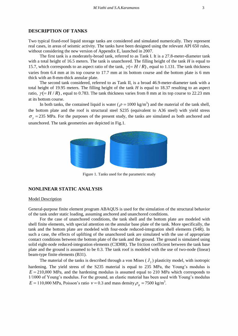
DESCRIPTION OF TANKS
Two typical fixed-roof liquid storage tanks are considered and simulated numerically. They represent
real cases, in areas of seismic activity. The tanks have been designed using the relevant API 650 rules,
without considering the new version of Appendix E, launched in 2007.
The first tank is a moderately-broad tank, referred to as Tank I. It is a 27.8-meter-diameter tank
with a total height of 16.5 meters. The tank is unanchored. The filling height of the tank H is equal to
15.7, which corresponds to an aspect ratio of the tank, ( / )H R , equal to 1.131. The tank thickness
varies from 6.4 mm at its top course to 17.7 mm at its bottom course and the bottom plate is 6 mm
thick with an 8-mm-thick annular plate.
The second tank considered, referred to as Tank II, is a broad 46.9-meter-diameter tank with a
total height of 19.95 meters. The filling height of the tank H is equal to 18.37 resulting to an aspect
ratio, ( / )H R , equal to 0.783. The tank thickness varies from 8 mm at its top course to 22.23 mm
at its bottom course.
In both tanks, the contained liquid is water ( 1000 kg/m3) and the material of the tank shell,
the bottom plate and the roof is structural steel S235 (equivalent to A36 steel) with yield stress
y 235 MPa. For the purposes of the present study, the tanks are simulated as both anchored and
unanchored. The tank geometries are depicted in Fig.1.
Figure 1. Tanks used for the parametric study
NONLINEAR STATIC ANALYSIS
Model Description
General-purpose finite element program ABAQUS is used for the simulation of the structural behavior
of the tank under static loading, assuming anchored and unanchored conditions.
For the case of unanchored conditions, the tank shell and the bottom plate are modeled with
shell finite elements, with special attention on the annular base plate of the tank. More specifically, the
tank and the bottom plate are modeled with four-node reduced-integration shell elements (S4R). In
such a case, the effects of uplifting of the unanchored tank are simulated with the use of appropriate
contact conditions between the bottom plate of the tank and the ground. The ground is simulated using
solid eight-node reduced-integration elements (C3D8R). The friction coefficient between the tank base
plate and the ground is assumed to be 0.3. The tank roof is modeled with the use of two-node (linear)
beam-type finite elements (B31).
The material of the tanks is described through a von Mises ( 2J ) plasticity model, with isotropic
hardening. The yield stress of the S235 material is equal to 235 MPa, the Young’s modulus is
E 210,000 MPa, and the hardening modulus is assumed equal to 210 MPa which corresponds to
1/1000 of Young’s modulus. For the ground, an elastic material has been used with Young’s modulus
E 110,000 MPa, Poisson’s ratio v 0.3 and mass density g 7500 kg/m3.
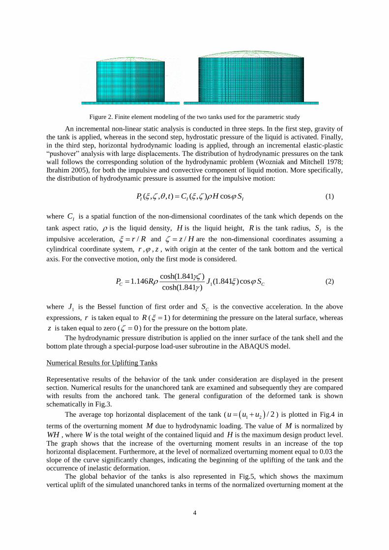
4
Figure 2. Finite element modeling of the two tanks used for the parametric study
An incremental non-linear static analysis is conducted in three steps. In the first step, gravity of
the tank is applied, whereas in the second step, hydrostatic pressure of the liquid is activated. Finally,
in the third step, horizontal hydrodynamic loading is applied, through an incremental elastic-plastic
“pushover” analysis with large displacements. The distribution of hydrodynamic pressures on the tank
wall follows the corresponding solution of the hydrodynamic problem (Wozniak and Mitchell 1978;
Ibrahim 2005), for both the impulsive and convective component of liquid motion. More specifically,
the distribution of hydrodynamic pressure is assumed for the impulsive motion:
( , , , ) ( , ) cosI I IP t C H S (1)
where IC is a spatial function of the non-dimensional coordinates of the tank which depends on the
tank aspect ratio, is the liquid density, H is the liquid height, R is the tank radius, IS is the
impulsive acceleration, /r R and /z H are the non-dimensional coordinates assuming a
cylindrical coordinate system, r , , z , with origin at the center of the tank bottom and the vertical
axis. For the convective motion, only the first mode is considered.
1
cosh(1.841 )1.146 (1.841 )cos
cosh(1.841 )C CP R J S
(2)
where 1J is the Bessel function of first order and CS is the convective acceleration. In the above
expressions, r is taken equal to R ( 1 ) for determining the pressure on the lateral surface, whereas
z is taken equal to zero ( 0 ) for the pressure on the bottom plate.
The hydrodynamic pressure distribution is applied on the inner surface of the tank shell and the
bottom plate through a special-purpose load-user subroutine in the ABAQUS model.
Numerical Results for Uplifting Tanks
Representative results of the behavior of the tank under consideration are displayed in the present
section. Numerical results for the unanchored tank are examined and subsequently they are compared
with results from the anchored tank. The general configuration of the deformed tank is shown
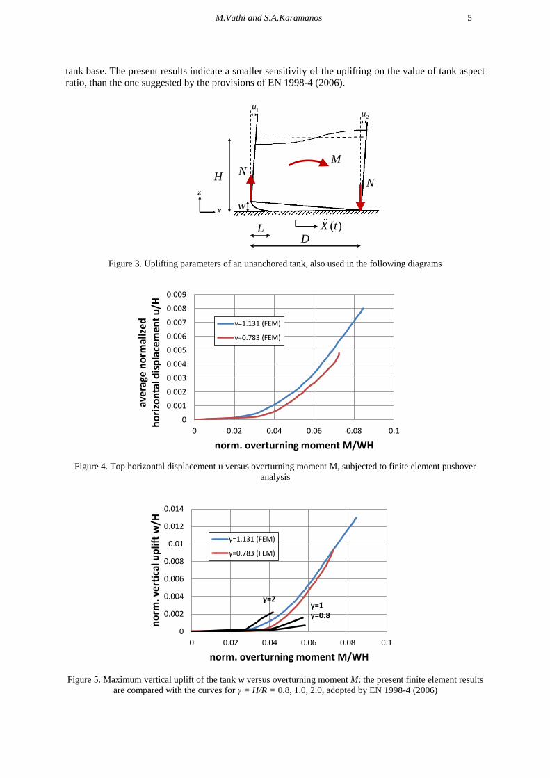
schematically in Fig.3.
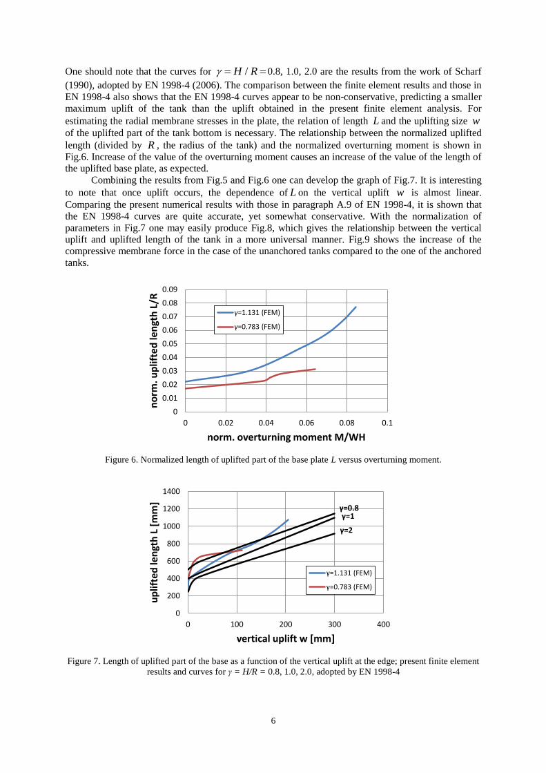
The average top horizontal displacement of the tank ( 1 2 / 2u u u ) is plotted in Fig.4 in
terms of the overturning moment M due to hydrodynamic loading. The value of M is normalized by
WH , where W is the total weight of the contained liquid and H is the maximum design product level.
The graph shows that the increase of the overturning moment results in an increase of the top
horizontal displacement. Furthermore, at the level of normalized overturning moment equal to 0.03 the
slope of the curve significantly changes, indicating the beginning of the uplifting of the tank and the
occurrence of inelastic deformation.
The global behavior of the tanks is also represented in Fig.5, which shows the maximum
vertical uplift of the simulated unanchored tanks in terms of the normalized overturning moment at the
M.Vathi and S.A.Karamanos 5
tank base. The present results indicate a smaller sensitivity of the uplifting on the value of tank aspect
ratio, than the one suggested by the provisions of EN 1998-4 (2006).
( )X tD
L
w
NN
1u2u
H
M
z
x
Figure 3. Uplifting parameters of an unanchored tank, also used in the following diagrams
0
0.001
0.002
0.003
0.004
0.005
0.006
0.007
0.008
0.009
0 0.02 0.04 0.06 0.08 0.1
ave
rage
no
rmal
ize
d
ho
rizo
nta
l dis
pla
cem
en
t u
/H
norm. overturning moment M/WH
γ=1.131 (FEM)
γ=0.783 (FEM)
Figure 4. Top horizontal displacement u versus overturning moment M, subjected to finite element pushover
analysis
0
0.002
0.004
0.006
0.008
0.01
0.012
0.014
0 0.02 0.04 0.06 0.08 0.1
no
rm. v
ert
ical
up
lift
w/H
norm. overturning moment M/WH
γ=1.131 (FEM)
γ=0.783 (FEM)
γ=1γ=2
γ=0.8
Figure 5. Maximum vertical uplift of the tank w versus overturning moment M; the present finite element results
are compared with the curves for γ = H/R = 0.8, 1.0, 2.0, adopted by EN 1998-4 (2006)
6
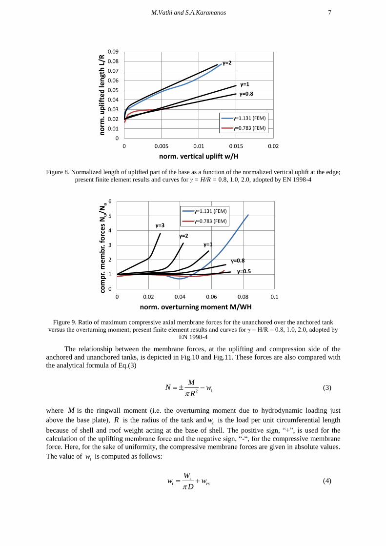
One should note that the curves for /H R 0.8, 1.0, 2.0 are the results from the work of Scharf
(1990), adopted by EN 1998-4 (2006). The comparison between the finite element results and those in
EN 1998-4 also shows that the EN 1998-4 curves appear to be non-conservative, predicting a smaller
maximum uplift of the tank than the uplift obtained in the present finite element analysis. For
estimating the radial membrane stresses in the plate, the relation of length L and the uplifting size w
of the uplifted part of the tank bottom is necessary. The relationship between the normalized uplifted
length (divided by R , the radius of the tank) and the normalized overturning moment is shown in
Fig.6. Increase of the value of the overturning moment causes an increase of the value of the length of
the uplifted base plate, as expected.
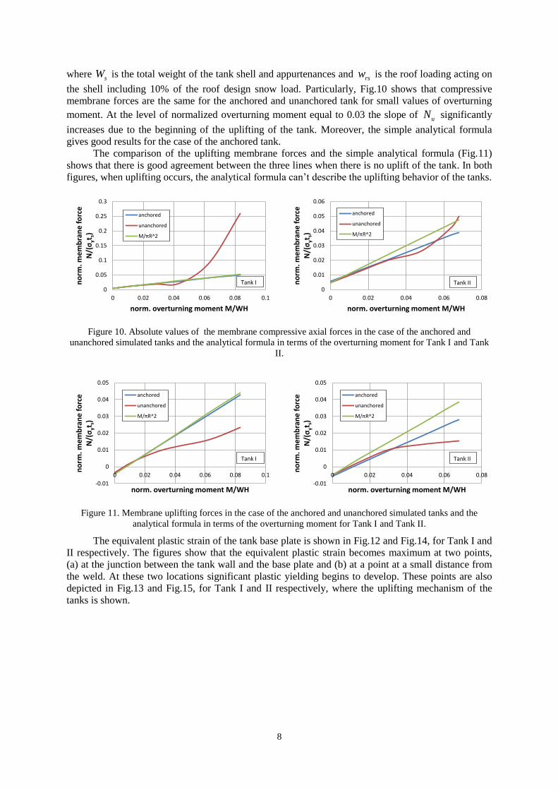
Combining the results from Fig.5 and Fig.6 one can develop the graph of Fig.7. It is interesting
to note that once uplift occurs, the dependence of L on the vertical uplift w is almost linear.
Comparing the present numerical results with those in paragraph A.9 of EN 1998-4, it is shown that
the EN 1998-4 curves are quite accurate, yet somewhat conservative. With the normalization of
parameters in Fig.7 one may easily produce Fig.8, which gives the relationship between the vertical
uplift and uplifted length of the tank in a more universal manner. Fig.9 shows the increase of the
compressive membrane force in the case of the unanchored tanks compared to the one of the anchored
tanks.
0
0.01
0.02
0.03
0.04
0.05
0.06
0.07
0.08
0.09
0 0.02 0.04 0.06 0.08 0.1
no
rm. u
plif
ted
len
gth
L/R
norm. overturning moment M/WH
γ=1.131 (FEM)
γ=0.783 (FEM)
Figure 6. Normalized length of uplifted part of the base plate L versus overturning moment.
0
200
400
600
800
1000
1200
1400
0 100 200 300 400
up
lifte
d le
ngt
h L
[m
m]
vertical uplift w [mm]
γ=1.131 (FEM)
γ=0.783 (FEM)
γ=1γ=0.8
γ=2
Figure 7. Length of uplifted part of the base as a function of the vertical uplift at the edge; present finite element
results and curves for γ = H/R = 0.8, 1.0, 2.0, adopted by EN 1998-4
M.Vathi and S.A.Karamanos 7
0
0.01
0.02
0.03
0.04
0.05
0.06
0.07
0.08
0.09
0 0.005 0.01 0.015 0.02
no
rm. u
plif
ted
len
gth
L/R
norm. vertical uplift w/H
γ=1.131 (FEM)
γ=0.783 (FEM)
γ=2
γ=0.8
γ=1
Figure 8. Normalized length of uplifted part of the base as a function of the normalized vertical uplift at the edge;
present finite element results and curves for γ = H/R = 0.8, 1.0, 2.0, adopted by EN 1998-4
0
1
2
3
4
5
6
0 0.02 0.04 0.06 0.08 0.1
com
pr.
me
mb
r. f
orc
es
Nu/N
a
norm. overturning moment M/WH
γ=1.131 (FEM)
γ=0.783 (FEM)
γ=2
γ=3
γ=1
γ=0.8
γ=0.5
Figure 9. Ratio of maximum compressive axial membrane forces for the unanchored over the anchored tank
versus the overturning moment; present finite element results and curves for γ = H/R = 0.8, 1.0, 2.0, adopted by
EN 1998-4
The relationship between the membrane forces, at the uplifting and compression side of the
anchored and unanchored tanks, is depicted in Fig.10 and Fig.11. These forces are also compared with
the analytical formula of Eq.(3)
2 t
MN w
R (3)
where M is the ringwall moment (i.e. the overturning moment due to hydrodynamic loading just
above the base plate), R is the radius of the tank and tw is the load per unit circumferential length
because of shell and roof weight acting at the base of shell. The positive sign, “+”, is used for the
calculation of the uplifting membrane force and the negative sign, “-“, for the compressive membrane
force. Here, for the sake of uniformity, the compressive membrane forces are given in absolute values.
The value of tw is computed as follows:
st rs
Ww w
D (4)
8
where sW is the total weight of the tank shell and appurtenances and rsw is the roof loading acting on
the shell including 10% of the roof design snow load. Particularly, Fig.10 shows that compressive
membrane forces are the same for the anchored and unanchored tank for small values of overturning
moment. At the level of normalized overturning moment equal to 0.03 the slope of uN significantly
increases due to the beginning of the uplifting of the tank. Moreover, the simple analytical formula
gives good results for the case of the anchored tank.
The comparison of the uplifting membrane forces and the simple analytical formula (Fig.11)
shows that there is good agreement between the three lines when there is no uplift of the tank. In both
figures, when uplifting occurs, the analytical formula can’t describe the uplifting behavior of the tanks.
0
0.05
0.1
0.15
0.2
0.25
0.3
0 0.02 0.04 0.06 0.08 0.1
no
rm. m
em
bra
ne
fo
rce
N
/(σ
yts)
norm. overturning moment M/WH
anchored
unanchored
M/πR^2
Tank I
0
0.01
0.02
0.03
0.04
0.05
0.06
0 0.02 0.04 0.06 0.08n
orm
. me
mb
ran
e f
orc
e
N/(
σyt
s)norm. overturning moment M/WH
anchored
unanchored
M/πR^2
Tank II
Figure 10. Absolute values of the membrane compressive axial forces in the case of the anchored and
unanchored simulated tanks and the analytical formula in terms of the overturning moment for Tank I and Tank
II.
-0.01
0
0.01
0.02
0.03
0.04
0.05
0 0.02 0.04 0.06 0.08 0.1
no
rm. m
em
bra
ne
fo
rce
N
/(σ
yts)
norm. overturning moment M/WH
anchored
unanchored
M/πR^2
Tank I
-0.01
0
0.01
0.02
0.03
0.04
0.05
0 0.02 0.04 0.06 0.08
no
rm. m
em
bra
ne
fo
rce
N
/(σ
yts)
norm. overturning moment M/WH
anchored
unanchored
M/πR^2
Tank II
Figure 11. Membrane uplifting forces in the case of the anchored and unanchored simulated tanks and the
analytical formula in terms of the overturning moment for Tank I and Tank II.
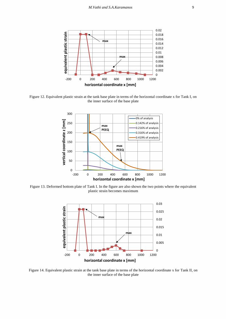
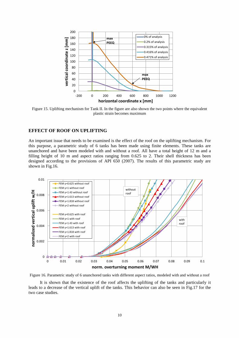
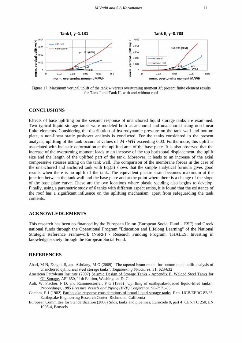
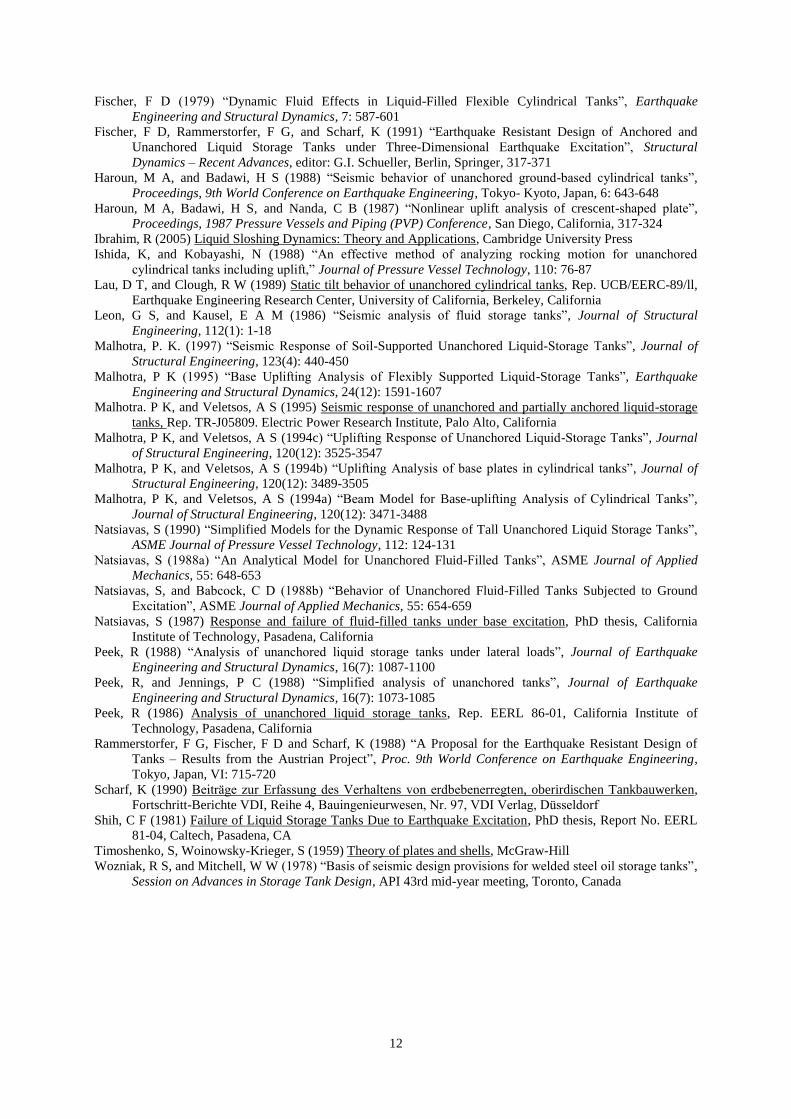
The equivalent plastic strain of the tank base plate is shown in Fig.12 and Fig.14, for Tank I and
II respectively. The figures show that the equivalent plastic strain becomes maximum at two points,
(a) at the junction between the tank wall and the base plate and (b) at a point at a small distance from
the weld. At these two locations significant plastic yielding begins to develop. These points are also
depicted in Fig.13 and Fig.15, for Tank I and II respectively, where the uplifting mechanism of the
tanks is shown.
M.Vathi and S.A.Karamanos 9
0
0.002
0.004
0.006
0.008
0.01
0.012
0.014
0.016
0.018
0.02
-200 0 200 400 600 800 1000 1200
eq
uiv
ale
nt
pla
stic
str
ain
horizontal coordinate x [mm]
max
max
Figure 12. Equivalent plastic strain at the tank base plate in terms of the horizontal coordinate x for Tank I, on
the inner surface of the base plate
0
50
100
150
200
250
300
-200 0 200 400 600 800 1000 1200
vert
ical
co
ord
inat
e z
[m
m]
horizontal coordinate x [mm]
0% of analysis
0.142% of analysis
0.216% of analysis
0.316% of analysis
0.419% of analysis
max PEEQ
max PEEQ
Figure 13. Deformed bottom plate of Tank I. In the figure are also shown the two points where the equivalent
plastic strain becomes maximum
0
0.005
0.01
0.015
0.02
0.025
0.03
-200 0 200 400 600 800 1000 1200
eq
uiv
ale
nt
pla
stic
str
ain
horizontal coordinate x [mm]
max
max
Figure 14. Equivalent plastic strain at the tank base plate in terms of the horizontal coordinate x for Tank II, on
the inner surface of the base plate
10
0
20
40
60
80
100
120
140
160
180
200
-200 0 200 400 600 800 1000 1200
vert
ical
co
ord
inat
e z
[m
m]
horizontal coordinate x [mm]
0% of analysis
0.2% of analysis
0.315% of analysis
0.416% of analysis
0.471% of analysis
max PEEQ
max PEEQ
Figure 15. Uplifting mechanism for Tank II. In the figure are also shown the two points where the equivalent
plastic strain becomes maximum
EFFECT OF ROOF ON UPLIFTING
An important issue that needs to be examined is the effect of the roof on the uplifting mechanism. For
this purpose, a parametric study of 6 tanks has been made using finite elements. These tanks are
unanchored and have been modeled with and without a roof. All have a total height of 12 m and a
filling height of 10 m and aspect ratios ranging from 0.625 to 2. Their shell thickness has been
designed according to the provisions of API 650 (2007). The results of this parametric study are
shown in Fig.16.
0
0.002
0.004
0.006
0.008
0.01
0 0.01 0.02 0.03 0.04 0.05 0.06 0.07 0.08 0.09 0.1
no
rmal
ize
d v
ert
ical
up
lift
w/H
norm. overturning moment M/WH
FEM γ=0.625 without roof
FEM γ=1 without roof
FEM γ=1.43 without roof
FEM γ=1.613 without roof
FEM γ=1.818 without roof
FEM γ=2 without roof
FEM γ=0.625 with roof
FEM γ=1 with roof
FEM γ=1.43 with roof
FEM γ=1.613 with roof
FEM γ=1.818 with roof
FEM γ=2 with roof
without roof
withroof
Figure 16. Parametric study of 6 unanchored tanks with different aspect ratios, modeled with and without a roof
It is shown that the existence of the roof affects the uplifting of the tanks and particularly it
leads to a decrease of the vertical uplift of the tanks. This behavior can also be seen in Fig.17 for the
two case studies.
M.Vathi and S.A.Karamanos 11
0
0.01
0.02
0.03
0.04
0 0.02 0.04 0.06 0.08 0.1
no
rm. v
ert
ical
up
lift
w/H
norm. overturning moment M/WH
Tank I, γ=1.131
with roof
without roof
γ=0.8γ=1γ=2
γ=1.131 (FEM)
0
0.004
0.008
0.012
0.016
0.02
0 0.02 0.04 0.06 0.08
no
rm. v
ert
ical
up
lift
w/H
norm. overturning moment M/WH
Tank II, γ=0.783
with roof
without roofγ=2
γ=0.8
γ=0.783 (FEM)
γ=1
Figure 17. Maximum vertical uplift of the tank w versus overturning moment M; present finite element results
for Tank I and Tank II, with and without roof
CONCLUSIONS
Effects of base uplifting on the seismic response of unanchored liquid storage tanks are examined.
Two typical liquid storage tanks were modeled both as anchored and unanchored using non-linear
finite elements. Considering the distribution of hydrodynamic pressure on the tank wall and bottom
plate, a non-linear static pushover analysis is conducted. For the tanks considered in the present
analysis, uplifting of the tank occurs at values of /M WH exceeding 0.03. Furthermore, this uplift is
associated with inelastic deformation at the uplifted area of the base plate. It is also observed that the
increase of the overturning moment leads to an increase of the top horizontal displacement, the uplift
size and the length of the uplifted part of the tank. Moreover, it leads to an increase of the axial
compressive stresses acting on the tank wall. The comparison of the membrane forces in the case of
the unanchored and anchored tank with Eq.(3) shows that the simple analytical formula gives good
results when there is no uplift of the tank. The equivalent plastic strain becomes maximum at the
junction between the tank wall and the base plate and at the point where there is a change of the slope
of the base plate curve. These are the two locations where plastic yielding also begins to develop.
Finally, using a parametric study of 6 tanks with different aspect ratios, it is found that the existence of
the roof has a significant influence on the uplifting mechanism, apart from safeguarding the tank
contents.
ACKNOWLEDGEMENTS
This research has been co‐financed by the European Union (European Social Fund – ESF) and Greek
national funds through the Operational Program "Education and Lifelong Learning" of the National
Strategic Reference Framework (NSRF) ‐ Research Funding Program: THALES. Investing in
knowledge society through the European Social Fund.
REFERENCES
Ahari, M N, Eshghi, S, and Ashtiany, M G (2009) “The tapered beam model for bottom plate uplift analysis of
unanchored cylindrical steel storage tanks”, Engineering Structures, 31: 623-632
American Petroleum Institute (2007) Seismic Design of Storage Tanks - Appendix E, Welded Steel Tanks for
Oil Storage, API 650, 11th Edition, Washington, D. C.
Auli, W, Fischer, F D, and Rammerstorfer, F G (1985) “Uplifting of earthquake-loaded liquid-filled tanks”,
Proceedings, 1985 Pressure Vessels and Piping (PVP) Conference, 98-7: 71-85
Cambra, F J (1982) Earthquake response considerations of broad liquid storage tanks, Rep. UCB/EERC-82/25,
Earthquake Engineering Research Center, Richmond, California
European Committee for Standardization (2006) Silos, tanks and pipelines, Eurocode 8, part 4, CEN/TC 250, EN
1998-4, Brussels
12
Fischer, F D (1979) “Dynamic Fluid Effects in Liquid-Filled Flexible Cylindrical Tanks”, Earthquake
Engineering and Structural Dynamics, 7: 587-601
Fischer, F D, Rammerstorfer, F G, and Scharf, K (1991) “Earthquake Resistant Design of Anchored and
Unanchored Liquid Storage Tanks under Three-Dimensional Earthquake Excitation”, Structural
Dynamics – Recent Advances, editor: G.I. Schueller, Berlin, Springer, 317-371
Haroun, M A, and Badawi, H S (1988) “Seismic behavior of unanchored ground-based cylindrical tanks”,
Proceedings, 9th World Conference on Earthquake Engineering, Tokyo- Kyoto, Japan, 6: 643-648
Haroun, M A, Badawi, H S, and Nanda, C B (1987) “Nonlinear uplift analysis of crescent-shaped plate”,
Proceedings, 1987 Pressure Vessels and Piping (PVP) Conference, San Diego, California, 317-324
Ibrahim, R (2005) Liquid Sloshing Dynamics: Theory and Applications, Cambridge University Press
Ishida, K, and Kobayashi, N (1988) “An effective method of analyzing rocking motion for unanchored
cylindrical tanks including uplift,” Journal of Pressure Vessel Technology, 110: 76-87
Lau, D T, and Clough, R W (1989) Static tilt behavior of unanchored cylindrical tanks, Rep. UCB/EERC-89/ll,
Earthquake Engineering Research Center, University of California, Berkeley, California
Leon, G S, and Kausel, E A M (1986) “Seismic analysis of fluid storage tanks”, Journal of Structural
Engineering, 112(1): 1-18
Malhotra, P. K. (1997) “Seismic Response of Soil-Supported Unanchored Liquid-Storage Tanks”, Journal of
Structural Engineering, 123(4): 440-450
Malhotra, P K (1995) “Base Uplifting Analysis of Flexibly Supported Liquid-Storage Tanks”, Earthquake
Engineering and Structural Dynamics, 24(12): 1591-1607
Malhotra. P K, and Veletsos, A S (1995) Seismic response of unanchored and partially anchored liquid-storage
tanks, Rep. TR-J05809. Electric Power Research Institute, Palo Alto, California
Malhotra, P K, and Veletsos, A S (1994c) “Uplifting Response of Unanchored Liquid-Storage Tanks”, Journal
of Structural Engineering, 120(12): 3525-3547
Malhotra, P K, and Veletsos, A S (1994b) “Uplifting Analysis of base plates in cylindrical tanks”, Journal of
Structural Engineering, 120(12): 3489-3505
Malhotra, P K, and Veletsos, A S (1994a) “Beam Model for Base-uplifting Analysis of Cylindrical Tanks”,
Journal of Structural Engineering, 120(12): 3471-3488
Natsiavas, S (1990) “Simplified Models for the Dynamic Response of Tall Unanchored Liquid Storage Tanks”,
ASME Journal of Pressure Vessel Technology, 112: 124-131
Natsiavas, S (1988a) “An Analytical Model for Unanchored Fluid-Filled Tanks”, ASME Journal of Applied
Mechanics, 55: 648-653
Natsiavas, S, and Babcock, C D (1988b) “Behavior of Unanchored Fluid-Filled Tanks Subjected to Ground
Excitation”, ASME Journal of Applied Mechanics, 55: 654-659
Natsiavas, S (1987) Response and failure of fluid-filled tanks under base excitation, PhD thesis, California
Institute of Technology, Pasadena, California
Peek, R (1988) “Analysis of unanchored liquid storage tanks under lateral loads”, Journal of Earthquake
Engineering and Structural Dynamics, 16(7): 1087-1100
Peek, R, and Jennings, P C (1988) “Simplified analysis of unanchored tanks”, Journal of Earthquake
Engineering and Structural Dynamics, 16(7): 1073-1085
Peek, R (1986) Analysis of unanchored liquid storage tanks, Rep. EERL 86-01, California Institute of
Technology, Pasadena, California
Rammerstorfer, F G, Fischer, F D and Scharf, K (1988) “A Proposal for the Earthquake Resistant Design of
Tanks – Results from the Austrian Project”, Proc. 9th World Conference on Earthquake Engineering,
Tokyo, Japan, VI: 715-720
Scharf, K (1990) Beiträge zur Erfassung des Verhaltens von erdbebenerregten, oberirdischen Tankbauwerken,
Fortschritt-Berichte VDI, Reihe 4, Bauingenieurwesen, Nr. 97, VDI Verlag, Düsseldorf
Shih, C F (1981) Failure of Liquid Storage Tanks Due to Earthquake Excitation, PhD thesis, Report No. EERL
81-04, Caltech, Pasadena, CA
Timoshenko, S, Woinowsky-Krieger, S (1959) Theory of plates and shells, McGraw-Hill
Wozniak, R S, and Mitchell, W W (1978) “Basis of seismic design provisions for welded steel oil storage tanks”,
Session on Advances in Storage Tank Design, API 43rd mid-year meeting, Toronto, Canada


![Unanchored Tank Connections [Bull. EE-2012].pdf](https://static.fdocuments.us/doc/165x107/577cc3821a28aba71196336d/unanchored-tank-connections-bull-ee-2012pdf.jpg)