Modeling of Radio Access Application Protocols for Mobile ... · Modeling of Radio Access...
180
Modeling of Radio Access Application Protocols for Mobile Network Traffic Generation Suliman Kahled Albasheir A Thesis in The Department of Electrical and Computer Engineering Presented in Partial Fulfillment of the Requirements for the Degree of Master of Applied Science (Electrical &; Computer Engineering) at Concordia University Montreal, Quebec, Canada December 2008 © Suliman Kahled Albasheir, 2008
Transcript of Modeling of Radio Access Application Protocols for Mobile ... · Modeling of Radio Access...

Modeling of Radio Access Application Protocols for Mobile Network Traffic Generation
Suliman Kahled Albasheir
A Thesis
in
The Department
of
Electrical and Computer Engineering
Presented in Partial Fulfillment of the Requirements
for the Degree of Master of Applied Science (Electrical &; Computer Engineering)
at
Concordia University
Montreal, Quebec, Canada
December 2008
© Suliman Kahled Albasheir, 2008

1*1 Library and Archives Canada
Published Heritage Branch
395 Wellington Street Ottawa ON K1A 0N4 Canada
Bibliotheque et Archives Canada
Direction du Patrimoine de I'edition
395, rue Wellington OttawaONK1A0N4 Canada
Your file Voire reference ISBN: 978-0-494-63199-7 Our file Notre reference ISBN: 978-0-494-63199-7
NOTICE: AVIS:
The author has granted a nonexclusive license allowing Library and Archives Canada to reproduce, publish, archive, preserve, conserve, communicate to the public by telecommunication or on the Internet, loan, distribute and sell theses worldwide, for commercial or noncommercial purposes, in microform, paper, electronic and/or any other formats.
L'auteur a accorde une licence non exclusive permettant a la Bibliotheque et Archives Canada de reproduce, publier, archiver, sauvegarder, conserver, transmettre au public par telecommunication ou par Nnternet, preter, distribuer et vendre des theses partout dans le monde, a des fins commerciales ou autres, sur support microforme, papier, electronique et/ou autres formats.
The author retains copyright ownership and moral rights in this thesis. Neither the thesis nor substantial extracts from it may be printed or otherwise reproduced without the author's permission.
L'auteur conserve la propriete du droit d'auteur et des droits moraux qui protege cette these. Ni la these ni des extraits substantiels de celle-ci ne doivent etre imprimes ou autrement reproduits sans son autorisation.
In compliance with the Canadian Privacy Act some supporting forms may have been removed from this thesis.
Conformement a la loi canadienne sur la protection de la vie privee, quelques formulaires secondaires ont ete enleves de cette these.
While these forms may be included in the document page count, their removal does not represent any loss of content from the thesis.
Bien que ces formulaires aient inclus dans la pagination, il n'y aura aucun contenu manquant.
1+1
Canada
ABSTRACT
Modeling of Radio Access Application Protocols for Mobile Network Traffic
Generation
Suliman Kahled Albasheir
Telecommunication applications have become some of the most important as
pects of our daily life, especially with the Internet-based applications that are avail
able even on cell phones. One of the challenges faced by telecom companies is to
provide robust and powerful servers that are capable to handle the great increase of
the number of subscribers and to accomplish the heavy Internet-based applications
that generate a tremendous traffic load. Telecom companies evaluate their prod
ucts' performance before releasing them to the market by applying a large amount
of generated traffic to the telecom servers in order to measure their capability under
traffic load. To do this, powerful solutions are needed, which generate traffic by
modeling different telecom protocols. In this thesis, we propose a new technique of
modeling a traffic generator solution to load the Mobile Switching Center (MSC) for
the Universal Mobile Telecommunications System (UMTS). This traffic generator
is modeled to load the MSC through various mobile call scenarios such as location
update, mobile call originating, mobile call terminating, and call clearing. Based
on that, we model the Radio Access Network Application Part protocol' procedures
to generate the radio access messages that carry and handle the mobile messages.
These mobile messages will be represented through the Mobility Management and
the Call Control protocols' models. To achieve the above goals, we utilize the UML
Use Case Model to describe the functional behaviors of the traffic generator, also we
present the UML Analysis Model that provides the logical implementation of the
functional behaviors of the proposed traffic generator.
m

ACKNOWLEDGEMENTS
First and foremost, I would like to express my great thanks to the Almighty
God, Who gave me the strength and patience to complete this work.
I would like to extend my sincerest gratitude for my supervisor Dr. Sofiene
Tahar, who has been a constant source of thoughtful guidance in pursuing this work.
Because of his input, advice, and challenge, I have matured as a researcher and as
a graduate student. I am very thankful for several people at Ericsson Montreal
Canada, Samir Douik and Teresa Marchut-Wierzbica for giving me an opportunity
to do my Master's project at Ericsson, Claude Gauthier, Jean Roussel Personna,
Martin Kirouac, and America Arredondo Garza for their guidance, mentoring, and
encouragement during my project. Also, many thanks to Marin Pin, Gennady
Bayder, and Martin Robinson for their technical support. I would also like to
acknowledge my thesis committee: Dr. Abdelwahab Hamou-Lhadj and Dr. Chadi
Assi for their valuable feedback on the thesis.
I would also like to take this opportunity to express my sincere thanks to my
colleagues in the Hardware Verification Group (HVG) of Concordia University for
their motivation, constructive suggestions, and helpful comments. In particular, I
would like to thank Naeern Abbasi for his time and valuable help during my thesis
writing. Special thanks go also to Dr. Ali Shatnawi, from Jordan University of
Science and Technology, for introducing me to the ECE Department at Concordia
University and to Dr. Sofiene Tahar.
I would like to thank all my friends and relatives in Montreal, Jordan, and
everywhere. Also, I am very grateful for my sisters, brothers, aunt, and grandparents
for the support and happiness they always provide me with. Finally, my sincere
thanks and deepest appreciation go out to my parents, Fatima and Khaled for their
affection, love, support, encouragement, and prayers to success in my missions.
iv

This thesis is dedicated to
My Mother Fatima Itwaiq
and
My Father Khaled Albasheir
v

TABLE OF CONTENTS
LIST OF FIGURES ix
LIST OF TABLES xii
LIST OF ACRONYMS xiii
1 Introduction 1
1.1 Motivation 1
1.2 Traffic Generation Design 4
1.3 Methodology 7
1.4 Related Work 10
1.5 Thesis Contribution 17
1.6 Thesis Outline 17
2 Proposed Architecture 19
2.1 RanapSim Components Description 19
2.1.1 Traffic Handler 19
2.1.2 RANAP Controller 25
2.1.3 SCCP Interface Controller 26
2.2 RanapSim Use-Case Model 27
2.2.1 Actors 28
2.2.2 Use Cases 30
2.3 UML Analysis Model Preliminaries 34
2.4 Summary 37
3 Traffic Handler 38
3.1 UML Analysis Classes 38
3.1.1 Messaging Proxies Classes 39
3.1.2 Traffic Handler Control Classes 44
VI
3.2 UML Use-Case Realization 49
3.2.1 Location Update Realization 49
3.2.2 Mobile Originating Call Realization 52
3.2.3 Mobile Terminating Call Realization 56
3.2.4 Traffic Handling Realization 60
3.3 UML Class Diagram 62
3.3.1 Location Update Class Diagram 63
3.3.2 Mobile Originating Call Class Diagram 65
3.3.3 Mobile Terminating Call Class Diagram 67
3.3.4 Traffic Handling Class Diagram 69
3.3.5 Traffic Messaging Class Diagrams 70
3.4 Summary 74
4 R A N A P and SCCP Controllers 75
4.1 RANAP Controller 75
4.1.1 UML Analysis Classes 76
4.1.2 UML Use-case Realization 77
4.1.3 UML Class Diagram 80
4.2 SCCP Interface Controller 82
4.2.1 UML Analysis Classes 83
4.2.2 UML Use-Case Realization 85
4.2.3 UML Class Diagram 90
4.3 Summary 91
5 Conclusion and Future Work 92
5.1 Conclusion , . . . . 92
5.2 Future Work 94
vn

A 96
A.l UML Analysis Classes 96
A.1.1 Messaging Proxies Classes 96
A.1.2 Traffic Handler Control Classes 120
A.1.3 RANAP and SCCP Controllers Classes 135
A.2 UML Use-Case Realization 147
A.3 UML Interfaces 156
A.4 CPP Platform Classes . 159
Bibliography 161
via
LIST OF FIGURES
1.1 Worldwide Mobile Subscription Growth [21] 2
1.2 Traffic Generation Environment for the Mobile Switching Center . . . 3
1.3 Traffic Generator Architecture 6
1.4 The UMTS Network Architecture 8
1.5 Protocol Stack 9
2.1 RanapSim Main Components 20
2.2 Traffic Handler Entities 21
2.3 RanapSim Use Case Diagram 29
2.4 UML Analysis Model 35
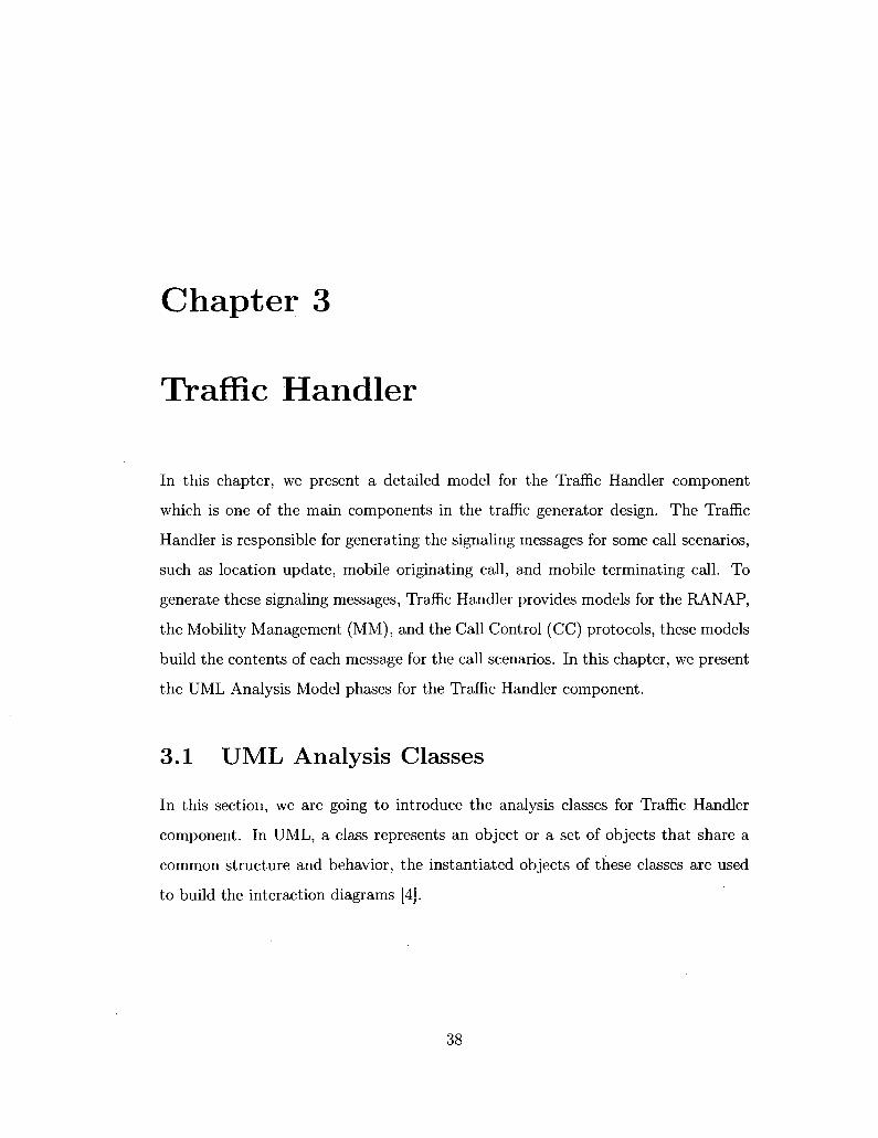
3.1 RANAP Message Proxy Class 40
3.2 Mobility Management Message Proxy Class 41
3.3 Call Control Message Proxy Class 43
3.4 Traffic Handling Controller Class 45
3.5 Location Update Controller Class 46
3.6 Call Originating Controller Class 47
3.7 Call Terminating Controller Class 47
3.8 Initial UE Message Controller Class 48
3.9 Location Update Sequence Diagram 51
3.10 Mobile Originating Call Sequence Diagram (parti) 53
3.11 Mobile Originating Call Sequence Diagram (part2) 55
3.12 Mobile Terminating Call Sequence Diagram (parti) 57
3.13 Mobile Terminating Call Sequence Diagram (part2) 59
3.14 Distinguish Call Scenarios Sequence Diagram 61
3.15 Location Update Class Diagram 64
IX
3.16 Mobile Originating Call Class Diagram 66
3.17 Mobile Terminating Call Class Diagram 68
3.18 Traffic Handling Class Diagram 69
3.19 RANAP Message Class Diagram 71
3.20 Mobility Management Message Class Diagram 72
3.21 Call Control Message Class Diagram 73
4.1 RANAP Interface Controller Class 76
4.2 RANAP Interface Form Class 77
4.3 Forward Call Scenario Messages Sequence Diagram 78
4.4 Forward CPP Response Messages Sequence Diagram 79
4.5 Control RANAP Class Diagram 81
4.6 SCCP Interface Controller Class 83
4.7 CPPSystem Class 84
4.8 Setup SCCPApfi Service Sequence Diagram 86
4.9 Interfacing for SCCP Sequence Diagram (parti) 87
4.10 Interfacing for SCCP Sequence Diagram (part2) 89
4.11 Interfacing for SCCP Class Diagram 90
A.l RANAP Message Proxy Class 96
A.2 Ranap Message Proxy's Entity Classes 102
A.3 Mobility Management Message Proxy Class 103
A.4 Mobility Managment Message Proxy's Entity Classes 110
A.5 Call Control Message Proxy Class I l l
A.6 Call Control Message Proxy's Entity Classes 119
A.7 Traffic Handling Controller Class 120
A.8 Location Update Controller Class 123
A.9 Call Originating Controller Class 124
A. 10 Call Terminating Controller Class 126
x

A. 11 Initial UE Message Controller Class 128
A. 12 Direct Transfer Controller Class 129
A.13 Security Mode Controller Class 131
A.14 Common Id Controller Class 132
A. 15 RAB Assignment Controller Class 132
A.16 Paging Controller Class 133
A.17 Iu Release Controller Class 134
A.18RANAP Interface Controller Class 135
A.19 RANAP Interface Form Class 137
A.20 SCCP Interface Controller Class 139
A.21 CPPSystem Class 143
A.22 Transfer To RANAP Controller Sequence Diagram 147
A.23 Transfer To Handler Sequence Diagram 148
A.24 Disconnect Command to the Mobile Originating Sequence Diagram . 149
A.25 Disconnect Message from the MSC to the Mobile Originating Se
quence Diagram 150
A.26 Disconnect Command to the Mobile Terminating Sequence Diagram .151
A.27 Disconnect Message from the MSC to the Mobile Terminating Se
quence Diagram 152
A.28 Disconnect SCCP Connection Sequence Diagram 153
A.29 Detach SCCPApfi Service Sequence Diagram 154
A.30 Attach SCCP Sequence Diagram 154
A.31 Call Scenario Commands Sequence Diagram . 155
A.32 Detach SCCP Sequence Diagram 156
A.33 UML Interface set 1 157
A.34 UML Interface set 2 158
A.35 CpxScciApfiProxy::CpxSccpApfiAttachP Class 159
A.36 CpxScciProxy::CpxScciP Class .160
xi

LIST OF TABLES
X l l
LIST OF ACRONYMS
AAL5 ATM Adaptation Layer Type 5
AP Access Point
API Application Programming Interface
ATM Asynchronous Transfer Mode
BHCA Busy Hour Call Attempts
CC Call Control
CM Connection Management
CN Core Network
CPP Ericsson Connectivity Packet Platform
CS Circuit Switch
EBSDL Entity Behavioral Specification and Description Lan
guage
GPRS General Packet Radio Service
GSM Global System for Mobile communications
HLR Home Location Register
ID Identifier
IE Information Element
IMSI International Mobile Subscriber Identity
IP Internet Protocol
Iu Interface links the RNC to either a MSC or a SGSN
IuCS Circuit Switched Interface links the RNC to a MSC
LAI Location Area Identifier
LAN Local Area Network
MGw Media Gateway
MGwSim Media Gateway Simulator
MM Mobility Management
xin

MOC
MS
MSC
MTC
NAS
NNI
PDU
QoS
RAB
RANAP
RNC
RRC
RSD
SAI
SCCI
SCCP
SccpApfi
SDL
SGSN
SNMP
SSCF
SSCOP
TMSI
UE
UMTS
UTRAN
WCDMA
Mobile Originating Call
Mobile Station
Mobile Switching Center
Mobile Terminating Call
Non Access Stratum
Network Node Interface
Protocol data unit
Quality of Service
Radio Access Bearer
Radio Access Network Application Part
Radio Network Controller
Radio Resource Control
Rational Systems Developer
Service Area Identifier
SCCP Interface
Signalling Connection Control Part
SCCP Access Point Facade Interface
Specification and Description Language
Service GPRS Support Node
Simple Network Management Protocol
Service Specific Coordination Function
Service Specific Connection Oriented Protocol
Temporary Mobile Subscriber Identity
User Equipment
Universal Mobile Telecommunications System
UMTS Terrestrial Radio Access Network
Wideband CDMA Code Division Multiple Access

Chapter 1
Introduction
1.1 Motivation
The Telecommunication industry has been growing tremendously during the last
decades. The International Telecommunication Union (ITU) reported that world
wide mobile cellular subscribers are likely to reach the 4 billion mark before the
end of this year with an estimated mobile penetration rate reaches 61% as shown
in Figure 1.1 [21]. Also, it is reported in [22] that the global Telecommunication
revenue will reach $2.0 trillion USD by the end of 2008, an increase of 7.6% over
revenues in 2007.
Based on the 61% estimated mobile penetration rate, this means there is a
possibility to have more and more subscribers into the telecom networks. On the
other hand, with the new next generation networking technology, more and more
internet-protocol-based applications are introduced or planed to be implemented in
the future.
Consequently, all these parameters require powerful telecom servers that are
capable to handle the tremendous increase of the subscribers' number and to carry
out the heavy next generation applications that generate huge traffic loads. It is
extremely important for the telecom companies to have powerful servers that capable
1

Figure 1.1: Worldwide Mobile Subscription Growth [21]
to carry out the huge telecom traffic loads, to achieve that, testing engineers in
telecom companies apply huge amount of simulated traffic to their telecom devices
to measure their capability and behavior under the pressure; this kind of test is
called Load Testing. Based on the load testing measurements, design engineers can
modify the design of the system to have more robust systems under the traffic load.
To do load testing, it is very important to have a powerful solution that simu
lates telecom protocols, initiates call scenarios, interacts with the telecom network,
as well as generates traffic messages towards the corresponding device under test;
we call this operation Traffic Generation.
The traffic generation can be achieved through several techniques such as;
software solution, hardware solution, or hybrid solution. The software solution is
very slow and the generated traffic is neither accurate nor realistic, also using a
software solution is not easy to interface with the real system. By using a hardware
solution to generate traffic with real components, we obtain a very fast, realistic,
2

robust, but costly solution. Using a hybrid solution that contains hardware and
software together, we may obtain a trade-off between speed, realistic traffic, robust
system, and cost.
In this thesis, we introduce a technique of modeling a traffic generator to do
load testing for the Mobile Switching Center that measures the capability and per
formance of the Mobile Switching Center under traffic pressure and does not actually
verify or check the design of this Center. The proposed traffic generator provides
models for the Radio Access Network Application Part, the Mobility Management,
and the Call Control protocols for the Circuit Switched network.
Apply huge amount of traffic to the telecom devices to measure their capability
under traffic pressure.
luCS MSC
(Device Under Test)
: Control Plane (signaling)
: User Plane (speech)
Figure 1.2: Traffic Generation Environment for the Mobile Switching Center
Figure 1.2 shows the traffic generation environment for loading the Mobile
Switching Center (MSC). Typically, to generate traffic in order to load the MSC,
many solutions model the whole Universal Mobile Telecommunications System Ter
restrial Radio Access Network (UTRAN) components' protocols, these components
are; the User Equipment (UE), radio base transceiver station (Node-B), and Radio
3

Network Controller (RNC). Obviously, it is not cost effective to simulate all these
components and their protocols in order to load the MSC server.
Our proposed modeling technique simulates only the messages on the interface
between the Radio Network Controller (RNC) and the MSC server; these messages
are the Radio Access Network Application Part (RANAP) message, the Mobility
Management message, and the Call Control message portions. The interface between
the RNC and the MSC called IuCS, this interface is used for circuit switched data
transfer.
Furthermore, our proposed design for traffic generation is modeled based on
an Ericsson proprietary platform called CPP [5]. The Ericsson Connectivity Packet
Platform (CPP) is a very powerful node used for emulation and protocol transporta
tion in many applications within Ericsson globally, it provides a high rate of calls
generation (1000 calls/sec). It is expected that our proposed design economizes in
using real telecom equipments; since our design provides models for the radio access
network messages, so it does not require real component such as the Radio Network
Controller to generate the traffic.
1.2 Traffic Generat ion Design
One of the components of the Ericsson's WCDMA/GSM Core Network is the MSC
Server, which is an entity that controls the setup and the release of the communica
tion connections in the network. The actual connections are handled by the Media
Gateway (MGw), which are driven by the MSC server using the Gateway Control
Protocol (GCP) protocol.
To simulate an environment around the MSC for load testing first, we have
to simulate the Media Gateway (MGw) that handles the GCP protocol. The MGw
Simulation (MGwSim) is a tool developed by Ericsson, it interacts with the MSC
and generates GCP protocol traffic, this tool is used for the MSC load testing [16].
4
Second, we have to generate the messaging traffic which simulates the RNC and
other components of the UTRAN (Node-B and UE). To generate this traffic, testing
engineers at Ericsson use either MGTS [27] or 3GSim [30] traffic generation tools
along with the MGwSim to generate messaging traffic that properly load the MSC
server.
In this thesis, we propose to model all messages between the MSC and RNC on
the IuCS interface; this means no models will be provided to simulate the messages
between the Node-B and the UE. All components in the proposed Traffic Generator
will be modeled based on the CPP platform. Since the MGwSim is built on the CPP
platform, this gives a capability to co-locate the MGwSim and our traffic generator
on one CPP node to apply traffic load towards the MSC. The CPP platform version
that is used for the current design is CPP 7.0 [5].
In real application, many call scenarios load the MSC server such as; mobile
location update, mobile call originating, mobile call terminating, call waiting and
forwarding, roaming call scenario, and others; but the mobile originating, mobile
terminating, and location update call scenario can be responsible for most of the
messages that load the MSC. Based on this, we consider those three call scenarios
to generate the load traffic. In addition, most of the testing activities done by the
industry for the MSC load actually concentrate on those three call scenarios.
In the traffic generator design, we concentrate on the modeling of the control
plane messaging (signaling); no models will be provided for the user plane messaging
(speech). An external tool for user plane traffic generation will be used to provide
the speech load. In this thesis, we propose a model for the RANAP Simulator Traffic
Generator, hereafter referred to as the RanapSim.
Figure 1.3 shows the proposed traffic generator architecture where it illustrates
the main components, the CPP platform with its provided protocols, as well as the
MSC server which is the device under test. In this figure, there are two different
colors for the architecture components that can be explained as follow;
5

Solaris/Linux/ Windows/ node
RanapSim CU
RanapSim GUI
RanapSim Server Node
RanapSim Server
TrafficHandler
RanapSim Manager
RanapController
SCCP Interface
Controller
Simulator Platform;
(CPP)
SCCP/ MTP-3b SSCF-NNIi AAL5
SSCOP-' ATM L1
j B : To be modefcd csmpsnems
gjfCPPpniSocolsist*
p^Oey&s under JesiiVSC)
MSC Server luCS Interface
Figure 1.3: Traffic Generator Architecture
The white color indicates that these components will be modeled in this thesis
and they represent the core of our proposed traffic generator. These components
are:
• Traffic Handler: The traffic handler is the main component for generating the
mobile call scenarios' traffic by modeling all required protocols.
• RANAP Controller: This component controls and handles all interactions
between the RanapSim components.
• SCCP Interface Controller: This component provides a connectivity function
ality between the RanapSim traffic generator and the CPP platform in order
to communicate with the MSC server.
These components will be explained in details in Chapters 2, 3, and 4.
6

The black color indicates that these components are assumed to be modeled
later on. These components are:
• RanapSim Manager: The Manager is the central entity that controls the traffic
generator simulation. Since this component is not modeled, we deal with it as
an external system with clear specifications.
• RanapSim Server: The Server is responsible for forwarding the requests to the
Manager, and transmitting the results back to the user.
• RanapSim GUI: The Graphical User Interface (GUI) provides a graphical in
terface to the simulator node for the user.
• RanapSim CLI: The Command Line Interface (CLI) provides a text-based
interface to the simulator node for the user.
1.3 Methodology
In the following, we describe the proposed methodology that we adopted to model
the traffic generator for the MSC load testing in the UMTS network. Figure 1.4
shows the UMTS network architecture and highlights the IuCS Interface that con
nects the RNC and the MSC, the transferred message over this interface contains
many protocols' headers which are; the MM, CC, RANAP, SCCP, MTP-3b, SSCF-
NNI, AAL5, SSCOP, and ATM [12].
Our methodology is to model only the Mobility Management (MM) and the
Call Control (CC) protocols (generated by the UE) and model the RANAP protocol
(generated by the RNC). The other protocols -that we have specified in the IuCS- are
not needed to be modeled, by taking advantage of using the CPP platform. CPP is
the Ericsson Connectivity Packet Platform, which is used for execution and transport
purposes; the execution part provides a support for software application execution,
7

: Control Plane (signaling)
; User Plane (speech) f
Figure 1.4: The UMTS Network Architecture
and the transport part provides connectivity functionality for several communication
protocols [5], where it provides a connectivity function for the physical layer protocol,
ATM protocol, up to the SCCP protocol.
Figure 1.5 shows the protocol stack provided by the CPP, the modeled pro
tocols for the RanapSim, and the MSC protocol stack. This figure illustrates that
RanapSim provides models for Mobility Management, and Call Control protocols
which are responsible for representing the UE signalling messaging, these protocols
should communicate with their corresponding protocols at the MSC server.
The RANAP protocol in the RanapSim represents the RNC signalling mes
sages where the UE messages portions are carried as well. From Figure 1.5, it is
obvious that RanapSim communicates with the CPP platform through the SCCP
protocol that controls the signalling connections, where CPP platform provides an
Application Programming Interface (API) based on the Unified Modeling Language
(UML) to facilitate the communication with it [5]. By modeling an interface through
the SCCP protocol, our model is able to communicate with and route messages to
8

| RanapSim |
.» « • : Physical Connection
: Virtual Connection
CPP Platform
J?ii!^£.!I!?.?§?JE5..._
'"'••:S^Of*v..;
• mP-0 -]?"<
SScNW - :
AAL5- ''•
:§scpp •;,,•;.
: '•:AtM:-:- '•.
• • . • . • i ^ | - : ' : ' ' . . " • ; . .
SCCP messages
MSC |
MM/CM/CC
RANAP
SCCP :. WTP>'3b''.
• ; SSOS-NNi
' ' AALS' ;
SSCOP
' " " • / 'ATM '?' :•.
L1- • . •,
Figure 1.5: Protocol Stack
the CPP platform.
By handling the RANAP, MM, and CC messages to the CPP platform through
the SCCP interface, the CPP is responsible for building the rest of the message by
providing the headers of the SCCP, MTP-3b, SSCF-NNI, AAL5, SSCOP,ATM,
and the physical layer protocols; the whole message will be forwarded by the CPP
through the physical connection to the MSC server. Once the MSC receives the mes
sage from the CPP, it will decode and process the whole message contents including
the generated RanapSim message portion. So, by utilizing the CPP transport func
tionality, we are exempted to model the rest of the protocol stack and this makes
our model more efficient. Using this technique, we are able to communicate and
load the MSC by the RANAP, the MM, and the CC messages without modeling
the whole UTRAN. From what we have explained, our model should provide three
main functionalities which are:
Generate signalling traffic (RANAP, MM, and CC modeling).
9

• Interact and interface with the CPP platform (SCCP interfacing).
• Control the interacting components.
Several Modeling languages can be used to model the RanapSim Traffic Gen
erator such as; the Unified Modeling Language (UML) [4] and the Specification
Description Language (SDL) [41]; since our model is needed to be implemented as a
tool using programming languages, so we consider the UML for modeling the traffic
generator. Furthermore, we use the Rational Systems Developer (RSD) from IBM
[3] to build the UML Use-Case Model and the UML Analysis Model which visually
show the functional specifications, describe the structure of the system, and explain
the interfacing between the system and its surroundings. The RSD tool is chosen
because it is one of the most popular tools for designing UML models that is used
in industry including Ericsson.
1.4 Related Work
In this section we present the related work in the area of protocol modeling and traffic
generation for telecommunication networks using various techniques and methodolo
gies. We will focus on traffic generation to load different telecommunication servers
and components such as the MSC server. Also, we will show the work for telecom
munication protocols modeling using different languages and techniques for various
telecommunication standards; such as Universal Mobile Telecommunications System
(UMTS) and Global System for Mobile communications (GSM). Furthermore, we
will show the importance of the traffic generation for protocol performance testing
and servers load testing in the telecommunication systems.
Since telecommunication networks and applications became more and more
complex, there is a need for an efficient design for traffic generation that supports
10

performance evaluation and load testing. For instance, the work in [32] proposes
a model for a traffic generation tool; this generator has been used to evaluate the
performance of some applications between GPRS and WLAN networks. This work
generates traffic by having traffic profiles produced by user-level software modules;
these traffic profiles may contain parametric traffic description such as; time dis
tributions and packet size information. The traffic will be generated by the traffic
engine by recognizing the parameterized information of the traffic profiles. This
work is an extension of a previous work described in [33] that presents an archi
tecture for a traffic generator capable of generating Asynchronous Transfer Mode
(ATM) traffic according to stochastic models. Although this model generates ATM
traffic, the main elements of the model can be used for generating traffic for other
networking technologies. In the work presented in this thesis, we propose a design for
traffic generator by modeling the RANAP, Mobility Management, and Call Control
protocols without using traffic profiles information.
In [36], the author provides an overview of computer-based simulation for
communications networks modeling, as well as some important related modeling
issues. Also, the work presents a traffic modeling for the ATM networks to test
multimedia and video services in the telecommunication networks. The Monte Carlo
computer simulation has been used for characterizing network resources needed for
traffic generation. The design we propose is not pure simulation since it is built
based on a hardware platform.
Another work has been presented in [37] for traffic generation modeling for
ad-hoc communication networks testing. It provides a Mobility Data Generator
that generates packets of mobile transceivers that usually communicate via radio
transmission. Along the same line of thought, the behavior of mobile transceivers
has been modeled in [42] to test and evaluate Mobile Ad-hoc Networks. In contrast,
the work in this thesis models the behavior of the mobiles call scenarios to generate
the required traffic to load the MSC server.
11

The work in [35] presents a multi- application traffic generator that can be used
to generate packets over a Local Area Network (LAN). The generator is capable to
test other types of communication systems; this can be done by changing the main
controller of the generator. In [38], the authors describe a software that simulates
mobile call scenarios such as mobile originated call and mobile terminated call for
the UMTS telecommunications system [40]. The provided simulator is capable to
generate RANAP messages on the interface between the MSC and the RNC. Using
the OMNeT++ simulator [39], some of the UMTS components have been simulated;
such as mobile equipment, Node B, RNC, Media Gateway, MSC Server, and others.
The generated messages by this work are extracted from some trace files and are
restructured to form new messages, but still these messages not really generated as
are those coming out from real network components. Also, this work describes the
functionality of the simulated communication system using SDL (Specification and
Description Language) [41]. The mobile originated call and the mobile terminated
call scenarios in the UMTS system have been described and modeled using a sort
of sequence diagrams that show all required RANAP, Mobility Management, and
Call Control messages to simulate the mobile call scenarios. However, this soft
ware still cannot be used for testing real equipment, but in order to utilize it for
real network load testing, it requires having connectivity functionalities to the real
UMTS communication servers, for instance the MSC server. In this thesis, we pro
vide models for the RANAP, Mobility Management, and Call Control protocols to
emulate mobile originating call, mobile terminating call, and location update mobile
call scenarios for the UMTS system in order to load the MSC server. Our model is
capable to interact with the MSC server, since it is built based on the CPP platform
which provides a connectivity functionality with the MSC.
In [43] [44], the authors propose a modeling technique for location operations
in a UMTS Network. These operations belong to both core network and access net
work under the Mobility Management protocol. For location operations modeling.
12

the work of [45] [46] provides functional blocks that represent various components
in the UMTS, such as UE, Node B, RNC, MSC, and others to simulate the location
operations. SDL [41] and MSC (Message Sequence Charts) [47] have been used for
modeling in this work. The provided model still can be improved by implementing
the designed test outputs in the presence of physical implementations of network el
ements. In contrast, our models are capable to communicate with the MSC through
the CPP platform.
The work in [19], presents a simulation model for the UTRAN, the simulated
model has been used to check the UTRAN Quality of Service (QoS) requirements
of the ATM links that connect the Node-B and the RNC. Along the same line
of thought, the simulation has been used in [17] [18] to model and simulate the
UTRAN, which contains UE, Node-B, RNC, and the interfaces between them. An
analytical approach has been used to characterize the traffic and to evaluate the
UTRAN performance. In our work, we do not simulate the UTRAN to test its
performance, we model some of the UTRAN protocol generate real traffic on the
IuCS interface.
In [20], the author concentrates on modeling the Mobility Management traffic
load and illustrates the impact of this traffic load on the MSC server. The author
describes preliminary information of the Mobility Management protocol parameters
that has an impact of load the MSC. This load represents a signaling traffic related
to the services provided by Mobility Management protocol, such as location update,
paging procedure, authentication, and ciphering process. Our work models the
Mobility Management protocol procedures and also models the Call Control protocol
procedures that build the mobile call scenarios.
In [23], the work provides a design for a protocol controller to handle the
communication functions at the Data Link layer between the MSC and the Base
Station Controller (BSC) in the GSM mobile networks. The Message Transfer Part
(MTP) protocol is responsible for these communication functions at the Data Link
13

layer. Our work concentrates on the protocol modeling between the RNC and the
MSC for the UMTS networks.
The work in [48] indicates that the location update mobiles' calls can be re
sponsible of about 80% of the random accesses to the radio channel in the GSM
networks. This fact indicates the significant impact of the traffic load on the MSC
due to the Mobility Management signaling messages. The work in [34] proposes
new techniques of test generation for communication standards, it indicates that
communication software requires a lot from load testing to get reliable systems.
Telecommunication companies are spending a lot of money for testing activity (up
to 50% of overall development costs). This indicates the necessity of providing and
modeling traffic generators for various communication standards to support systems
testing.
Several languages and techniques have been used to model the telecommuni
cation standards protocols. As we have mentioned before, the work in [38] [45] [46]
[49] have used SDL [41] and MSCs [47] in modeling. The modeling part in [24]
uses Entity Behavioral Specification and Description Language (EBSDL) to model
the SCCP protocol. The Simple Network Management Protocol (SNMP) has been
modeled in [25] using the Unified Modeling Language (UML). The Use-Case Model
and the Analysis Model have been described for the SNMP protocol modeling. An
other work using UML in [26] provides an approach for network traffic modeling,
which can be used in load testing to discover the faults of a system under test,
Sequence Diagrams and Class Diagrams have been modeled to describe the logical
implementation of the functional requirements. In this thesis, we make use of UML
to model the traffic generator protocols and call scenarios where we build the Use
Case Model, define the analysis classes, illustrate the sequence diagrams, and build
the class diagrams.
Commercial Tools
Many companies have been working on designing and developing tools for
14

traffic generation, which can be used for telecommunication systems load testing and
performance evaluation. Those tools provide various solutions for traffic modeling
of most of the telecommunication systems protocols using different methodologies
and techniques.
The Message Generator Traffic Simulator (MGTS) testing tool [27] is a solution
provided by CATAPULT Communications. Another solution is developed by the
same company, which is the Digital Communications Test System (DCT2000) [28].
These tools provide a variety of models for protocol simulation and traffic generation.
MGTS and DCT2000 provide a simulation for all nodes and their interfaces protocols
in the UTRAN (UE, Node-B, and RNC). The simulated UTRAN is used to generate
traffic towards the MSC in order to do the load testing. The RANAP, the Mobility
Management, and the Call Control protocols have been modeled in the simulated
UTRAN. MGTS and DCT2000 require lots of scripting efforts from the end-users
to implement the test scenarios scripts which will represent the call scenarios for
the mobile communications. Those solutions are designed to run on a proprietary
platforms provided by Catapult.
The Polystar company developed the SOLVER System [29], which is a load
test tool for various telecommunication networks. It provides the ability to simulate
the UTRAN for GSM/GPRS and UMTS with a number of connected mobile stations
providing load to the MSC and other devices in the Core Network. SOLVER does
not require lots of scripting efforts to implement the test call scenarios but it is not
flexible to have customized test scenarios, also it supports a limited number of call
scenarios. A proprietary platform from Polystar is used to run SOLVER to execute
the required call scenarios.
Ericsson has developed a Third Generation Simulator (3Gsim) solution [30],
as a load generator for traffic simulation in the UMTS networks. 3Gsim is used
for the RNC load testing. 3Gsim can simulate some nodes in the UMTS network:
the UE, the Node-B, the MSC, the SGSN, as well as the interfaces between them.
15

By simulating these UMTS nodes, 3Gsim is capable of generating traffic to load
the RNC. In order to be able to load the MSC it should use real RNC's to gen
erate traffic towards the MSC server, but this is a costly strategy since it requires
real components to generate traffic. 3Gsim provides command-based functionality
to create traffic scenarios and to control the simulation. 3Gsim is built on CPP
(Ericsson Connectivity Packet Platform) [5].
The UMTS Traffic Model Simulator (UTMS) [31], is another solution devel
oped by Ericsson; it is used to generate traffic for the Media Gateway (MGw) load
testing in the UMTS and GSM networks. UTMS simulates the signaling part of the
radio access in the RNC and the BSC to load the MGw. UTMS is not designed to
load the MSC, but it is possible to do that by using real MGw to simulate complete
environment for the MSC. This makes the using of UTMS to load the MSC costly
since it uses real component. UTMS is built on CPP (Ericsson Connectivity Packet
Platform) [5].
In this thesis, we present a technique to model a traffic generator to load the
MSC server in the UMTS networks. In this work, we use UML to model the RANAP,
the Mobility Management, and the Call Control protocols on the IuCS Interface.
Our technique does not require models for the UE, the Node-B, or the RNC; this
makes our approach cost effective and more efficient than other techniques and mod
els that we have highlighted earlier in this section. To load the MSC, those modeled
protocols (RANAP, MM, and CC) provide mobile call scenarios; such as location
update, mobile call originating, mobile call terminating, and call clearing scenarios.
We build our models based on the Ericsson Connectivity Packet Platform (CPP)
where the interfacing with this platform will be through the Signalling Connection
Control Part (SCCP) protocol.
16

1.5 Thesis Contribution
The contribution of this thesis is as follows:
• We have provided an efficient technique to generate signaling messages towards
the MSC server in order to do the load testing.
• We have modeled the Radio Access Network Application Part (RANAP) pro
tocol's procedures in order to generate the radio access network messages in
the IuCS Interface.
• We have modeled the mobile radio interface protocols in the UMTS network;
one of these protocols are the Mobility Management, which has been utilized
to model the mobile location update call scenario. In addition, the Call Con
trol protocol has been modeled to generate signalling messages of the mobile
originating call, the mobile terminating call, and the call disconnect scenarios.
All of these call scenarios are required to simulate the mobile stations of the
network.
• We have built the UML Use Case Model and the Analysis Model for the
RanapSim traffic generator design, where we have described the logical imple
mentation of the functional requirements for the proposed design.
• Through the UML models, we have modeled connectivity functionality for the
traffic generator design to communicate with the Ericsson Connectivity Packet
Platform (CPP) through the SCCP protocol.
1.6 Thesis Outline
This thesis is made up of six chapters. In Chapter 2, we provide a brief overview for
the traffic generator architecture, where we introduce the main components of the
architecture and we describe the most important functionalities for each component.
17

In addition, we present the Use Case Model to realize the functional behavior of the
proposed architecture; also we define and explain the model's Actors and the Use
Cases. In Chapter 3, we provide detailed explanation for the Traffic Handler compo
nent and describe deeply the modeling for the RANAP, the mobility management,
and the call control protocols. Also, we provide the UML Analysis Model for this
component, where we define the analysis classes, build the Use Case realization, and
illustrate the class diagrams.
In Chapter 4, we describe the RANAP Controller component which is the main
controller for the whole traffic generator design; we realize the main functionalities
for this component through describing the analysis classes, the Use Case realization,
and the class diagrams. Also, we present the SCCP Interfacing Controller compo
nent, where we explain the interfacing functionality with the CPP platform through
illustrating the analysis classes, the Use Case realization, and the class diagrams. In
Chapter 5, we summarize and conclude the achieved work, and we present some fu
ture work hints. Finally, Appendix A contains some UML analysis classes, sequence
diagrams, and interfaces which are implemented for the Analysis Model.
18

Chapter 2
Proposed Architecture
This chapter gives a brief overview of the detailed architecture of the RANAP sim
ulator traffic generator, also it provides the main functional description and respon
sibilities for all the RanapSim components. In addition, this Chapter interprets
the RanapSim functional behavior into UML Use Case Model. Figure 2.1 shows the
RanapSim main components which are the Traffic Handler, RANAP Controller, and
SCCP Interface Controller, also it illustrates how these component are connected to
the MSC server through the CPP platform; the RanapSim Manager is connected to
the RANAP Controller component to manage all components' operations.
2.1 RanapSim Components Description
This section explains briefly the functional description of the RanapSim traffic gen
erator that we are going to model, also it highlights the main components' function
alities of the RanapSim.
2.1.1 Traffic Handler
The Traffic Handler performs all traffic generation requests which come from the
Manager through the RANAP Controller, these requests show all call scenarios
19

that are supported by this model. This component is responsible for responding to
any signaling messages received from the MSC through the RANAP Controller and
sending the response back. Figure 2.2 shows the Traffic Handler's entities which
represent the main functionalities provided by this Traffic Handler; those entities
are the Main Traffic Handler, Location Update Entity, Call Originating Entity, and
Call Terminating Entity. These entities are explained briefly as follows:
RanapSim Manager
TrafficHandler
1 RanapController
| SCCP
Interface Controller
1
Simulator Platform (CPP1
MSC Server luCS interface
QiCPPplaifoTO
f ~ j . Dewce under test (MSC*
Figure 2.1: RanapSim Main Components
Main Traffic Handler
The Main Traffic Handler is the central entity that controls all signaling messages
that are received from the RANAP Controller or from the call scenarios entities.
This entity is responsible for forwarding messages to the corresponding call scenario
entity. The Main Traffic Handler responsibilities are:
Handle the Manager call scenario requests which are summarized as follows:
20

Location Update Entity
, Main Traffic Handler
Call Originating Entity
Call T*rinifiatteB •' Entity .;;
Figure 2.2: Traffic Handler Entities
— Handle the location update call scenario request, generate suggested con
nection identifier and connection state, and forward the call request to
the Location Update entity. The generated connection ID along with
connection state will be stored at the traffic handler and forwarded with
all messages related to the generated call scenario. This ID will become
the SCCP connection ID -at the CPP platform- which helps to distin
guish between different messages that belong to different calls. More
explanations will be given in Chapters 3 and 4.
— Handle the mobile call originating call scenario request, generate sug
gested connection ID, and forward the call request to the Mobile Origi
nating entity. There is no call scenario request for the mobile terminating
scenario, because it is triggered at some point in the mobile originating
scenario.
— Handle the call disconnect requests and forward them to either the Mobile
Originating entity or the Mobile Terminating entity, to force any of them
to disconnect and clear the call.
21

• Identify the received messages from the MSC by using the SCCP connection
ID which corresponds to a specific call scenario. After identifying the message,
the RANAP portion will be extracted from the messages and forwarded to the
right destination entity.
If the SCCP connection ID is unknown or not attached in the message, the
Handler will look deeper into the message contents to understand the message
type. So, if the hexadecimal value of the message type equal to "0014", this
means that the message is a PAGING Request which should be forwarded to
the Mobile Terminating entity to start the terminating side of the call.
• Receive signaling messages from the call scenario entities which will be for
warded to the RANAP Controller. If the handler receives a message from the
Mobile Terminating entity without having a connection ID, this means that
the received message is the response for the PAGING Request message. So, a
new connection ID and state will be created for the call scenario.
Location Update Entity
The location update procedure is used to update the registration of the actual
location area of a mobile station in the network [7], the Location Update entity
handles the traffic generation of the location update call scenarios for any request
received from the Manager. This entity should model the RANAP and the mobility
management (MM) protocols' messages; which is normally carried by the IuCS
interface between the RNC and the MSC.
The Location Update entity is responsible for initiating the Location Update
call scenario by sending the request message to the MSC; which will emulate the
mobile request for location update. In addition, this entity authenticates the con
nection with the MSC and performs other security procedures to secure and cipher
22

the connection with the MSC, all these procedures are usually done by the mo
bile station which updates its location. After that, the MSC sends a message that
contains the International Mobile Subscriber Identity (IMSI), this message will be
received by the entity to attach it to the emulated mobile station for identification
purposes.
Call Originating Entity
The call originating entity is responsible for establishing the mobile originating call,
which triggers the call terminating procedure to establish the mobile terminating
call in order to simulate the circuit-switched call between two mobile stations. The
Call Originating Entity handles the traffic generation of the originating call scenario
by modeling the RANAP, the MM, and the CC protocols' messages [9].
The Call Originating Entity is responsible for the following messages and op
erations:
• Communicate with the MSC to establish the MM connection through per
forming the Connection Management (CM) service procedure, authenticating
the connection with the MSC, and performing other security procedures to
secure and cipher the connection with the MSC.
• Initiate the call setup procedure. Upon establishing the MM connection and
receiving the IMSI, this entity shall send a SETUP message to the MSC.
• Receive a CALL PROCEEDING message from the MSC to indicate that the
call is being processed, and handle the RAB ASSIGNMENT procedure which
is normally initiated by the MSC to assign radio channel for specific mobile
station [6].
• Once the Radio Access Bearer (RAB) ASSIGNMENT procedure is completed,
the MSC will initiate a PAGING Request message to be sent to the Mobile
23
Terminating Entity -which is another entity from the Traffic Handler-. This
message enables the MSC to request the RNC to contact the terminating
mobile station. At this point, the call originating entity will wait for the MSC
to establish the call with the call terminating entity.
• Receive ALERTING message from the MSC, this indicates that the call termi
nating entity has setup the call with the MSC and initiated the ALERTING
message. After that, the call originating entity receives a CALL CONNECT
message from the MSC, and sends back a CONNECT ACKNOWLEDGMENT
message to the MSC.
Call Terminating Entity
The call terminating entity is responsible for responding to the originating call and
to simulate the mobile terminating call, which will be triggered by the PAGING
Request message.
The Call Originating entity is responsible for the following messages and op
erations:
• Communicate with the MSC to perform the PAGING procedure, where the call
terminating entity receives the PAGING Request message (RANAP Message)
- this message is used to find and contact the simulated terminating mobile
in the call terminating entity- and then responds by sending the PAGING
Response message (Mobility Management Message) [9].
• Authenticate the connection with the MSC server and perform the Security
Mode procedure.
• Receive the Common ID message which contains the International Mobile
Subscriber Identity (IMSI), interact with the MSC to complete the setup pro
cedure for the incoming call, and then send the CALL CONFIRMED message
to confirm the readiness to receive the call from the call originating entity.
24
• Complete the RAB ASSIGNMENT procedure with the MSC. The MSC initi
ates this procedure to assign radio channel for the call terminating entity.
• Send an ALERTING message to the MSC. Upon receiving this message, the
MSC sends a corresponding ALERTING message to the call originating entity.
• Send a CALL CONNECT message to the MSC which indicates that the call
terminating entity accepts the call. Upon receiving this message, the MSC
will send a CALL CONNECT message to the call originating entity.
Upon the CONNECT ACKNOWLEDGMENT message is received from the
MSC, the call will be started and the speech will be going on between the call
originating and the call terminating entities until a call clearing procedure is initiated
by the MSC or by any of the calling parties. The speech load is not provided by
this system; still we need a tool to provide the data plane (speech).
2.1.2 RANAP Controller
The RANAP Controller represents the main controller of the system, since it controls
all interactions between the traffic generator components and other external com
ponents. Also, it represents the connecting point between the RanapSim Manager,
the Traffic Handler, and the SCCP interface Controller. The RANAP Controller's
responsibilities are:
• Handle the SCCP Attach and the SCCP Detach requests. These requests
are initiated by the Manger to attach/detach the SCCP Access Point Facade
Interface (SCCPApfi), this interface handles the SCCP protocol's control plane
(signalling) in the CPP platform.
• Handle the Manager call scenarios requests for the call scenarios by forwarding
them to the Traffic Handler component in order to generate calls.
25

• Receive call scenario messages from the Traffic Handler and forward them to
the Manager (for tracing and following up purposes). Also, RANAP Controller
forwards these messages to the CPP platform which is connected to the MSC.
• Receive the MSC messages (responses/requests) which are sent through the
CPP platform, forward them to the Manager (for tracing and following up
purposes), as well as forward these messages to the Traffic Handler to complete
the call scenarios.
More details about this component are given in Chapter 4.
2.1.3 SCCP Interface Controller
The SCCP Interface Controller is a component that deals with the CPP platform
to control the SCCP connections, exchange messages, and interact with the CPP
interfaces which are based on the SCCP protocol. This controller is responsible for
handling all messages from/to the CPP, and the CPP itself will take the respon
sibility to interact with the MSC to accomplish our target of applying load to the
MSC.
The CPP platform provides various protocols that we can interact with, and
for each protocol there are many interfaces to deal with. In our case, we are dealing
with the SCCP protocol. The CPP platform provides two interfaces for the SCCP;
these interfaces are the control plane interface (SCCPApfi) and the user plane inter
face (SCCI). The SCCP Interface Controller's responsibilities can be summarized as
follows:
• Attach the SCCPApfi interface in order to use the SCCP service. This attach
request will be initiated by the Manager.
• Handle the SCCP connections for several call scenarios.
• Transfer data to the CPP platform in order to communicate with the MSC.
26

• Detach the SCCPApfi interface. No more SCCP services will be provided after
detaching this interface.
More details about this component are given in Chapter 4.
2.2 RanapSim Use-Case Model
The UML Use-Case Model describes a system's functional requirements in terms of
Use Cases. It consists of all Actors of the system and various Use Cases by which
the Actor interacts with the system, thereby describing the total functional behavior
of the system. Each Use Case describes the functionality to be built in the proposed
system, which can include another Use Case's functionality or extend another Use
Case with its own behavior [4].
The UML Use Case can be denned as a sequence of actions that a system
performs to achieve a specific functionality [4]. System's Use Case can be identified
by investigating the functions that the user wants from the system, communication
information between Actors about changes or events that the system must know
about, and information that must be modified or created.
The UML Actor can be defined as anyone or anything that interacts with the
system (the application), also it represents human, machine, or another system. Sys
tem's Actors can be identified by exploring anything uses or maintains the system,
the system's external resources, and other systems that interact with our system.
The interactions between the system's Use Cases and Actors can be realized
by UML Relationships. A UML relationship is a model element that defines the
structure and behavior between other model elements. Some of these relationships
are Association, Include, and extend relationships [1].
In this section, we make use of the Use-Case Model to interpret the functional
description of the RanapSim Traffic Generator into UML modeling elements. The
Use-Case Model considers the RanapSim system as a black box; this means that
27
the building blocks within the RanapSim should not be mentioned in the Use-Case
Model.
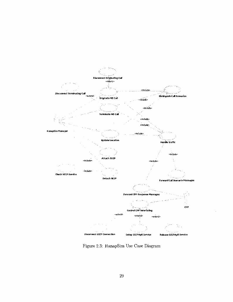
Figure 2.3 shows the Use Case diagram for the RanapSim Traffic Generator
Use Case Model. It shows that the Traffic Handler functionalities are interpreted into
seven Use Cases which are; the Update Location, Originate MS Call, Terminate MS
Call, Disconnect Originating Call, Disconnect Terminating Call, Distinguish Call
Scenarios, and Handle Traffic Use Cases. Also, The Use Case diagram illustrates
the RANAP Controller functionalities which are interpreted into the Attach SCCP,
Detach SCCP, Check SCCP Service, Forward Call Scenario Messages, and Forward
CPP Response Messages Use Cases.
Furthermore, the Use Case diagram explains all Use Cases that provide the
SCCP Interface Controller functionalities, these Use Cases are; the Control CPP In
terfacing, Disconnect SCCP Connection, Setup SCCPApfi Service, and Release SC-
CPApfi Service Use Cases. On the other hand, the CPP platform and the RanapSim
Manager component are represented as UML Actors in the Use Case diagram.
In next section, we describe in details the Use Case Model that reflects the
functional behavior of the RanapSim.
2.2.1 Actors
An Actor expresses the role of a user (human or external system) interacting with
the system. An Actor is not part of the system [1].
C P P
The CPP is an existing platform used for execution and transport with speci
fied interfaces for application design. The execution part consists of support for the
design of application hardware and software. The transport part, which can be seen
as an internal application on the execution platform, consists of several protocols for
communication and signaling. This traffic generator model shall be built based on
28
Disconnect Originatfrig Call « extendi
Disconnect Terminating Call
RanapSuii Manager
iriginate MS Call
erminate MS Cal
Update Location
j-« Include??
<< include^
«<irtdude>»
«incbdsi»> ""-•
"includes
''Z^-:~^'^---..:,.., >.;••• : ; '
Distinguish CaD Scenarios
'jS'" " '.-,
Handle Traffic
Attach SCCP «includes
«<include* Check SCCP Service
Detach SCCP Forward CaD Scenario Messages
Forward CPP Response Messages
« extends
Control CPP; Interfacing
.-extend., extend..
Disconnect SCCP Connection setup SCCPApfl Service Release SCCPApfi Service
Figure 2.3: RanapSim Use Case Diagram
29

the CPP platform specifications. Also, the CPP platform provides several protocols
and connectivity capabilities from the ATM protocol up to the SCCP protocol.
RanapSim Manager
The RanapSim Manager is an external system that manages the RanapSim
resources; also it controls the simulation through command bases. To facilitate the
dealing with this component, we assume that the RanapSim Manager is an external
system interacting with our main components and it is responsible for initiating the
call scenarios requests.
This Actor will be implemented to initiate the following call scenarios requests:
- SCCP Attach (CPP)
- SCCP Detach (CPP)
- Location Update
- Mobile Call Originating
- Originating Call Disconnect
- Terminating Call Disconnect
The Mobile Terminating call scenario will be initiated consequently by initi
ating the MS Call Originating request.
2.2.2 Use Cases
A Use Case should be used to express user-initiated functionality. All functionalities
should be expressed as Use Cases. The Include and the Extend relationships can
be used between Use Cases to express communications, options and possibilities
of reuse. These kinds of relations between Use Cases should be visualized in the
Use-Case Diagram [1].
30

Update Location
This Use Case describes how the Location Update call scenario can be gener
ated. The modeled Location Update is specified for the IMSI Attach purpose. Also,
this Use Case models all messages which normally go from the RNC to the MSC to
emulate the Location Update call scenario. This Use Case interacts with the MSC
to complete the Location Update call scenario.
Originate MS Call
This Use Case is started by the RanapSim Manager actor, it describes how the
mobile originating call can be generated. It models all messages which normally go
from the RNC to the MSC to emulate the originating call scenario. This Use Case
responds to the received messages from the MSC, some of the response messages
initiate the terminating call scenario at the terminating side to emulate a complete
call between the originating and the terminating sides.
Terminate MS Call
This Use Case is started by the RanapSim Manager actor. It describes how
a sequence of messages can be generated for establishing a call with the originat
ing side through the MSC server. It describes how the mobile station receives a
PAGING request from the MSC and how it responds to it. In addition, this Use
Case properly responds to all messages received from the MSC to complete the ter
minating call scenario, these responses are forwarded to the MSC to connect the
originating side to the terminating side of the call.
Disconnect Originating Call
This Use Case is started when the RanapSim Manager actor decides to discon
nect and clear the call from the originating side; this Use Case releases all occupied
resources for a call between the originating and terminating sides. This Use Case is
31

connected to the Originate MS Call Use Case through the extend relationship.
Disconnect Terminating Call
This Use Case is started when the RanapSim Manager actor wants to discon
nect and clear the call from the terminating side; this Use Case releases all occupied
resources for a call between the originating and terminating sides. This Use Case
is connected to the Terminate MS Call Use Case through the extend relationship [4].
Handle Traffic
This Use Case handles and controls the traffic issues of all the call scenarios, it
describes a sequence of messages for distinguishing between the various CPP plat
form response messages in order to route them to the proper call scenario based on
the SCCP connection identifier. This Use Case is connected to the Update Location,
Originate MS Call, Terminate MS Call, and Forward CPP Response Messages Use
Cases through the include relationships.
Distinguish Call Scenarios
This Use Case is responsible for generating an SCCP connection identifier for
a corresponding call scenario, and initiating a call scenario traffic generation which
can be identified based on the generated SCCP connection. This Use Case is con
nected to the Update Location, Originate MS Call, and Terminate MS Call Use
Cases through the include relationships.
Forward Call Scenario Messages
This Use Case describes how the generated call scenario messages are trans
ferred to the RanapSim Manager actor and the CPP platform actor. This Use Case
is connected to the Handle Traffic Use Case through the include relationship.
32

Forward C P P Response Messages
This Use Case illustrates how the response messages received from the CPP
platform actor can be forwarded to various call scenarios and to the RanapSim Man
ager actor. This Use Case is connected to the Handle Traffic Use Case through the
include relationship [4].
Attach SCCP
This Use Case is started by the RanapSim Manager to initiates the SCCP
service attachment operation; without attaching the service, call scenarios are not
allowed to communicate with the CPP platform.
Detach SCCP
This Use Case is started by the RanapSim Manager to initiate the SCCP
service detachment operation; call scenarios will not have any access to the CPP
platform after detaching this service.
Check SCCP Service
This Use Case makes sure that the SCCP service is attached before any call
scenario starts generating messages. This Use Case is included by the Attach SCCP
and Detach SCCP Use Cases through the include relationships.
Control C P P Interfacing
This Use Case allows the traffic generator to exchange messages with the CPP
platform through the SCCP protocol, it describes how to interact with the CPP
platform through the SCCP interface. Furthermore, this Use Case explains how to
establish an SCCP connection through the CPP platform for a specific call scenario,
and how to forward/receive messages to/from the CPP platform.
33
Disconnect C P P Connection
This Use Case describes how to disconnect the SCCP connection for a specific
call scenario at the CPP platform. This Use Case is connected to the Control CPP
Interfacing Use Case through the extend relationship [4].
Setup SCCPApfi Service
This Use Case describes how the SCCPApfi interface can be setup and at
tached at the CPP platform actor to utilize the provided service. This Use Case is
connected to the Control CPP Interfacing Use Case through the extend relationship.
Release SCCPApfi Service
This Use Case describes how the SCCPApfi interface can be released and de
tached at the CPP platform actor; no services will be provided after releasing this
interface. This Use Case is connected to the Control CPP Interfacing Use Case
through the extend relationship.
2.3 UML Analysis Model Preliminaries
This section describes the modeling elements of the UML Analysis Model, and it
introduces the techniques that will be followed in Chapter 3 and 4 to build the
Analysis Model for the RanapSim Traffic Generator's main components.
The Analysis Model describes the structure of the system or application that
we are modeling. It describes the logical implementation of the functional require
ments that we identified in the Use Case Model. The main purposes of the Analysis
Model are to: (1) identify the classes which perform a Use Case's flow of events, (2)
distribute the Use Case behavior to those classes through Use Case realizations, (3)
identify the responsibilities, attributes and associations of the classes, and (4) build
34

the Class Diagrams of the system. The Analysis Model consists of three phases,
which are Analysis Classes, Use Case realization, and Class Diagrams, Figure 2.4
shows the three phases that we follow to accomplish the Analysis Model [4].
The Analysis Classes represent an early conceptual model of the system which
contains many classes. The class is a description of a set of objects that share the
same attributes, operations, relationships, and semantics, any instance from a class
can be called object, and the object is an entity with a well-defined boundary and
identity that encapsulates state and behavior.
UMI An.ilv.sis Modi-]
Analyst-. • ;
Classes i " • 1 J
<T l i s t C.1M-
Realization ; ,
o i lassDiagr.n:is
"IBmUH'T
'
Figure 2.4: UML Analysis Model
The Analysis Classes is the first phase of the Analysis Model, it can be identi
fied based on three perspectives, which are; (1) a class is used to model interaction
between the system and its environment; this class represents a Boundary Class. The
boundary class can be a user-interface class, a device-interface class, or a system-
interface class. (2) A class is used to model the control behavior of one or more Use
35

Cases; this class represents a Control Class. (3) A class is used to model information
that must be stored; this class represents an Entity Class [2].
The second phase of the Analysis Model which is the UML Use Case Real
ization, this phase can be used to describe the behavior of the Use Case and to
identify the responsibilities, attributes and associations of the classes. The class
responsibilities can be characterized as the actions that the object can perform, or
the knowledge that the object maintains and provides to other objects [1].
To illustrate the Use Case realization, we use Sequence Diagram which is a
UML diagram that illustrates sequence of messages between objects in an interac
tion. It consists of a group of objects that are represented by lifelines and messages
that objects exchange within the interaction.
In most cases, we use sequence diagrams to illustrate use-case realizations
to show how objects interact to perform the behavior of a Use Case. One or more
sequence diagrams may illustrate the object interactions which represent a Use Case.
A typical organization is to have one sequence diagram for the main flow of events
and one Sequence Diagram for each independent sub-flow of the Use Case.
The UML Class Diagrams is the third phase of the Analysis Model which
shows a collection of declarative model elements, such as classes, interfaces, and
relationships. It is possible to use Class Diagrams to model the objects that make
up the system, to display the relationships between the objects, and to describe
what services provided by those objects [4].
Class Diagrams can be used to visualize, specify, and document structural
features in our models. In addition, class diagrams help to show the class roles and
responsibilities that define the behavior of the system, and it illustrates the structure
of a model by using attributes, operations, signals, and relationships.
During the Analysis Model, we can create class diagrams to capture and define
the structure of classes and to define relationships between classes. UML Relation
ships provide different types of connectivity between modeling elements, such as
36

Dependency, Association, Aggregation, Composition, Generalization, and Interface
realization relationships [4].
2.4 Summary
In this chapter, we have provided the functional description of the RanapSim Traffic
Generator architecture. We have described the main components of the proposed
traffic generator namely; the Traffic Handler, the RANAP Controller, and the SCCP
Interface Controller, where we have illustrated the main functionalities for each
component. The denned functional description of the RanapSim' components have
been interpreted into UML Use-Case Model, this model highlights the functional
behavior of the RanapSim components in terms of UML Use Cases and Actors.
The RanapSim's Use Case Model will be used by the Analysis Model to describe
the logical implementation of the system. The UML Analysis Model preliminaries
have been presented in this chapter; these preliminaries will be followed in Chapter
3 where we are going to introduce the detailed modeling of the Traffic Handler
component.
37
Chapter 3
Traffic Handler
In this chapter, we present a detailed model for the Traffic Handler component
which is one of the main components in the traffic generator design. The Traffic
Handler is responsible for generating the signaling messages for some call scenarios,
such as location update, mobile originating call, and mobile terminating call. To
generate these signaling messages, Traffic Handler provides models for the RANAP,
the Mobility Management (MM), and the Call Control (CC) protocols, these models
build the contents of each message for the call scenarios. In this chapter, we present
the UML Analysis Model phases for the Traffic Handler component.
3.1 U M L Analysis Classes
In this section, we are going to introduce the analysis classes for Traffic Handler
component. In UML, a class represents an object or a set of objects that share a
common structure and behavior, the instantiated objects of these classes are used
to build the interaction diagrams [4].
38

3.1.1 Messaging Proxies Classes
Traffic Handler component has three messaging proxies that are responsible for han
dling all operations related to the protocols' messages, these messages are; RANAP
message [6], Mobility Management message, and Call Control message [7]. Each
one of the messages has one control class that works as a proxy and many entity
classes that represent the message data elements. In this section, we give detailed
description about these messaging proxies' classes and their operations and data
elements.
R A N A P Message Proxy
The RANAP Message Proxy is represented by the control class which is shown
below, this proxy is responsible for receiving, preparing, forwarding, decoding, and
sending RANAP messages as well as performing a RANAP procedure that is re
quested by the incoming message. Several RANAP messages are represented in this
model as UML Entity classes and controlled by this proxy class; these messages
belong to different RANAP procedures that are required to build the signaling traf
fic for the modeled calls scenarios. These RANAP messages are; Direct Transfer,
Initial UE, Common ID, Security Mode Command, Security Mode Complete, RAB
Assignment, Paging Request, as well as Iu Release messages [8]. These messages
represent the RANAP portion of the generated traffic to load the MSC.
Figure 3.1 shows the UML representation for the RANAP Message Proxy class,
it illustrates the operations that are provided by the class. Generally, this class's
responsibilities are to: (1) receive and prepare request/response RANAP messages,
(2) communicate with the Mobility Management Message Proxy to get the MM
message part, (3) communicate with the Call Control Message Proxy to get the CC
message part, and (4) co-work with other control classes to perform the RANAP
procedures; for example get Direct Transfer Response.
39
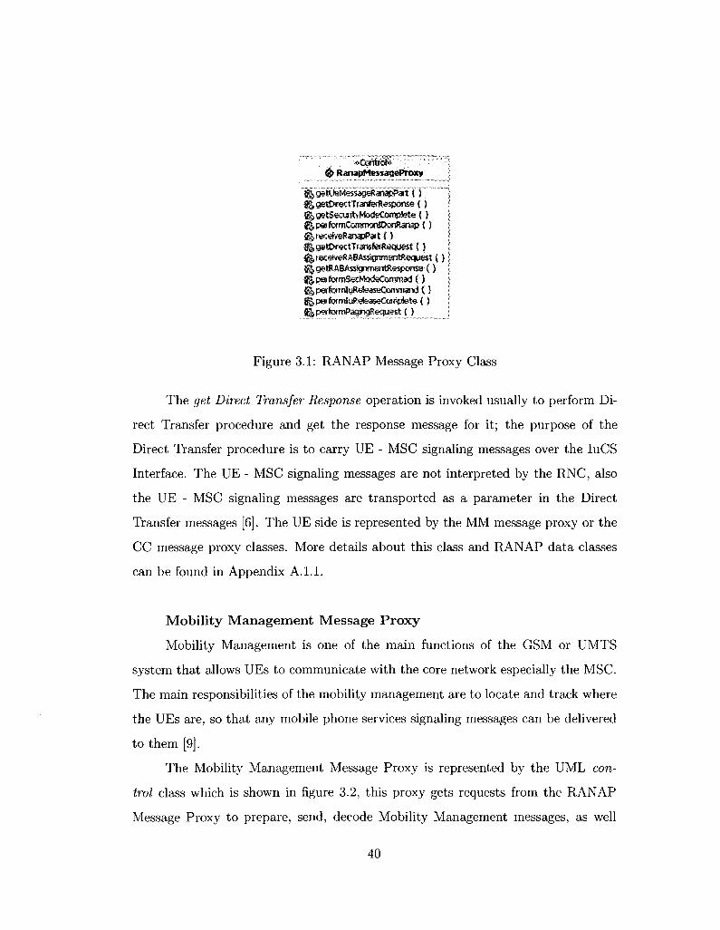
#> RanapMessageProxy
r^getUaStessa^Riri^Pa'tT) "} ! fj,getDif«;tTfanteRssp©ris« ( ) I : ^getSecurityMcxleComplet« { } I ; ^parformCoiwnonlOwTRanap ( ) I
! $getDrectTraisfeffteQuest { ) j i ^recefveRABA^grreaTWiequest ( } | | j getRABAssignmentRespense•( J j | ^psrform&cNQdeOoswnad ( ) j i jgperformluRGleaseGQnimand ( ) I ! ftpe!fbrm!u8^eas»C«jMete (5 I j IgjperfDrmPashgRecfue'St { ) I
Figure 3.1: RANAP Message Proxy Class
The get Direct Transfer Response operation is invoked usually to perform Di
rect Transfer procedure and get the response message for it; the purpose of the
Direct Transfer procedure is to carry UE - MSC signaling messages over the IuCS
Interface. The UE - MSC signaling messages are not interpreted by the RNC, also
the UE - MSC signaling messages are transported as a parameter in the Direct
Transfer messages [6]. The UE side is represented by the MM message proxy or the
CC message proxy classes. More details about this class and RANAP data classes
can be found in Appendix A. 1.1.
Mobility Management Message Proxy
Mobility Management is one of the main functions of the GSM or UMTS
system that allows UEs to communicate with the core network especially the MSC.
The main responsibilities of the mobility management are to locate and track where
the UEs are, so that any mobile phone services signaling messages can be delivered
to them [9].
The Mobility Management Message Proxy is represented by the UML con
trol class which is shown in figure 3.2, this proxy gets requests from the RANAP
Message Proxy to prepare, send, decode Mobility Management messages, as well
40

.; «C6ntrd» •' #Mobil ityManagmentMessageProxy
^"getLSOpdteqMmPi t ( } ^getMmResportse { ) ^authenticationReaction ( ) jf^focationUpdateAccept ( ) f^tecationUpdataComplete ( ) ^getCmServiceReqMmPai't ( ) UlreceiveMmPart ( ) ft startTlmer { ) ^stopTimer ( ) iJgetPagingRespQnseMmPart I) ^releaseMMconnection! ) lltocatlonLfcidateRej ( ) |j|,locatioriUpdatefailure ( ) ^performCmServiceAccepted (5 ^performCmServiceRejected ( } ^ceceiveAuthenticationRequest { )
Figure 3.2: Mobility Management Message Proxy Class
as perform a Mobility Management procedure that is requested by the RANAP
Message Proxy. In this model, the MM message proxy represents the UE mobil
ity portion, so it models and replaces the mobility portions of the UE. Various
Mobility Management messages are represented as UML Entity classes, each one
of these classes represent a specific type of mobility management actual message
that is related to one of the MM functionalities. In this model, the MM message
proxy class represents and models the mobility management portion of the real
UE. The MM messages that are provided by this model are; Location Update Re
quest/Accept/Reject, Authentication Request/Response/Reject, Connection Man
agement Service Request/Accept/Reject, as well as Paging Response messages [7].
These messages represent the UE mobility management portion message of the gen
erated signaling traffic to load the MSC. These messages' classes can be controlled
and accessed by the MM message proxy class to perform and complete the MM
requested services.
Figure 3.2 illustrates the operations and a data member that are provided by
the class. In general, this class's responsibilities are to: (1) receive and prepare
41
request/response MM messages, (2) provide mobility management messages to the
RANAP Message Proxy class to generate the UE message portion, (3) perform the
connection management services which is responsible for generating a MM connec
tion, (4) perform the authentication procedure at the UE side, and (5) perform the
location update procedure.
The location update procedure is handled by this class through some opera
tions. Normally, the location updating procedure is used to update the registration
of the actual location area of a UE in the network [9], the receive Location Update
Accept operation indicates that the UE's IMSI (International Mobile Subscriber
Identity) is recognized and activated by the MSC. Also, receive Location Update
Reject operation indicates that the UE's IMSI is not activated by the MSC. More
details about this class and MM data classes can be found in Appendix A. 1.1.
Call Control Message Proxy
Call Control is one of the GSM or UMTS system which use the mobility
management connection to allow UEs to establish and clear calls with the core
network especially MSC. The main responsibilities of call control are to allow the
UE to originate mobile call, terminate mobile call, and clear mobile call [9].
The Call Control Message Proxy is represented by the control class which is
shown in Figure 3.3, this proxy gets requests from the RANAP Message Proxy to
prepare, send, decode Call Control messages, as well as perform the call establish
ment or clearing procedures that are requested by the RANAP Message Proxy.
Different Call Control messages are represented as UML Entity classes in this
model, each one of these classes represents a specific type of call control actual
message that is related to one of the CC functionalities. In this model, the CC
message proxy class represents and models the call control portion of the real UE, so
it replaces the call control portions of the UE. The CC messages that are provided by
this model; Alerting, Setup, Call Proceeding, Call Confirm, Call Connect, Connect
Acknowledgment, Disconnect, Release, as well as Release Complete messages [7].
42

' "Control" • & CallControfMessaqeProxy _ _ _ SjjT313 '^sixtnrmj) l^getCcPat ( )
%stopT»ner ( ) ^sencteaSConimed ( ) $$endCaKomect ( } ^sendAtet&itftfassage ( )
$recedreCaKonnect (} { sendConnectAdsMessagB { ) f recefceSetupMsssage ( } ||recef»eConnectftdM8«age { ) f^serK&scomectMessage ( ) fllrecefoeRetease ( ) (giSendReteaseCQmptete { ) recefeeDBCoresectMessage t )
Figure 3.3: Call Control Message Proxy Class
These messages represent the UE call control portion message of the generated
signaling traffic to load the MSC. These messages' classes can be controlled and
accessed by the CC message proxy class to perform and complete the CC requested
functions.
The UML representation of the CC Message Proxy class is shown in Figure 3.3;
it demonstrates the operations and data members that are provided by the class.
In this model, the CC message proxy class's responsibilities are: (1) receive and
prepare request/response call control messages, (2) provide the call establishment
and call clearing messages to the RANAP Message Proxy class to generate the UE
message portion, (3) prepare and send the Setup message to MSC to initiate a mobile
call originating establishment, (4) perform both call proceeding and call confirming
requests that come from the MSC side, (5) perform the alerting, call connect, and
connect acknowledgment procedures at both terminating and originating call sides,
and (6) perform the call clearing procedure from for a specific CC entity which
43

represent the call control portion of a UE [10].
In this UML model, we provide the call connect and connect acknowledgment
through some operations that are provided by the CC proxy class. The CC proxy
class -at the mobile terminating side- indicates the MSC that the call has been
accepted at the called entity by invoking the send Call Connect operation. The CC
proxy class - at the mobile originating side- receives the call connect message from
the MSC by invoking the receive Call Connect operation, the received message by
this operation indicates that the call connection has been established by the MSC
[7]. More details about this class and CC data classes can be found in Appendix
A.1.1.
3.1.2 Traffic Handler Control Classes
In this section, we give details about the UML control classes for the Traffic Handler
component. These control classes are designed to handle and control all signaling
messages that are received from the RANAP Controller classes or from the Messag
ing proxies' classes. These classes contain the call scenarios classes and the RANAP
procedures classes. The following are the Traffic Handler's analysis classes with their
operations and data elements.
Traffic Handling Controller Class
The Traffic Handling Controller class is the main control class for the Traffic
Handler Component.
The Traffic Handling Controller class controls all interactions between the
Traffic Handler component and the RANAP Controller component, where this class
handles all signaling messages between the main call scenarios' control classes and
the RANAP Controller classes. Figure 3.4 shows the UML representation for this
class, it illustrates the operations and data members that are provided by the class.
44

^Control* & TrafficHandJingControlter
^ User Data « i sccpCoimectionldStataPtr i l f sccpConnecttonldPtr fgcaSScenarioReq { ) ^gsnerateSuggestedComectiortd (5 ^.trasferMassagetoHandter ( } g|i>ctentifyMess3geTyiK { ) fimessagelsUrtTiown ( } ||transferToHarKllaWithNloCorinectioriW (3
Figure 3.4: Traffic Handling Controller Class
As data members, this class provides the User Data that implies the RANAP mes
sage frame, the SCCP Connection ID that identifies the SCCP connection for each
call scenario, and the SCCP Connection ID State, which is an enumeration data
element, this data member is transferred between various components along with
the SCCP Connection ID. The SCCP Connection ID State holds values from 1 to
4, we summaries these values implications for the corresponding SCCP connection
as follows:
1: "connected": the SCCP connection is connected.
2: "disconnected": the SCCP connection is disconnected.
3: "generated": the SCCP connection is only generated.
4: " to be disconnected" the SCCP connection is intended to be disconnected.
Generally, the Traffic Handling Controller class is responsible for (1) control
ling the behavior of the call scenarios classes, (2) communicating with the RANAP
Controller classes to receive and forward the RANAP protocol message portion (User
Data), (3) identifying the received message -through the SCCP connection ID- and
forward it to the proper class object. More details about these class's operations
and data elements can be found in Appendix A.1.2.
45

Location Update Controller Class
The Location Update Controller class controls the location update call scenario
functionality in the Traffic Handler component.
# LocationUpdateController [^NSsraT"" : j igUserData j ^kkatfonlUJpdReq'() j f | trasferMessa^TctocatiorTUpdSm { ) \
Figure 3.5: Location Update Controller Class
Figure 3.5 shows the UML representation for the location update controller
class, this class communicates with the Traffic Handling Controller class to get the
relevant messages for a specific UE to accomplish the location update call scenario.
Also, it interacts with the RANAP proxy, mobility management proxy, and other
control classes to generate the sequence of signaling messages that provides the
location update traffic in order to load the MSC. More information about these
class responsibilities can be found in Section 3.2.1; and more details about the
class's operations and data member can be found in Appendix A.1.2.
Call Originating Controller Class
The Call Originating Controller class controls the mobile originating call sce
nario functionality in the Traffic Handler component.
The UML representation for the call originating class is shown in Figure 3.6,
the data elements and operations in this class contribute to model the mobile origi
nating call scenario. This class interacts with the Traffic Handling Controller class
to send and receive the mobile originating call messages, also it cooperates with
the RANAP, mobility management, and call control proxies classes to generate the
data messages. These messages are used by the Call Originating Controller class
as requests and responses to originate a call from UE and to interact with MSC to
46

«J CdllOriginatingController ' ipAS^PDO" """"" "•"" "" ' '••"" j 6|UserData 1 ^tSbir¥cttransfef&Rxtesportt« ( ) ' ! ^mohllsOrigReq ( ) j <§^ transfei MessageToMobOrigSlm E 3 i ^.transferDisconnectCommandToMobOrigSim { ) I-^setSccpConnectionidStateToBeDisconnected ( ) ;
Figure 3.6: Call Originating Controller Class
establish the call with the terminating mobile side. More information about the mo
bile originating call scenario can be found in Section 3.2.2. Also, this class provides
a capability to disconnect the call by releasing all related connections. More details
about the class's operations and data member can be found in Appendix A. 1.2.
Call Terminating Controller Class
The mobile terminating call scenario is controlled by the Call Terminating
Controller class.
# CailTerminatingController K | N A S - T O U " " i
K| UserData <jj§, thnsifa'MessaoeToMobiteTwmSiT) ( ) i j^tiansferrasconnectCommandToMobTeimSim ( ) : | | | setSccpConnectionldStateToBeDlscorinected ( ) :
Figure 3.7: Call Terminating Controller Class
As we mentioned before that the call originating controller class initiates the
call by interacting with the MSC, the MSC interacts with the Call Terminating
Controller Class to establish a call between originating and terminating mobiles.
The Call Terminating Controller class is provided by this model to represent the
mobile terminating side; this class interacts with the Call Originating Controller
class through the MSC server to generate all signalling messages for mobile calls.
47

By modeling originating and terminating calls, we will be able to load the MSC with
the generated messages [9].
Figure 3.7 shows the UML representation for the call terminating controller
class. It cooperates with the RANAP proxy, mobility management proxy, and call
control proxy classes to generate the required sequence of messages to simulate
the terminating mobile side. More information about the mobile terminating call
scenario can be found in Section 3.2.3. Also, this class is able to disconnect the call
through clearing all connections and releasing all occupied resources. More details
about the class's operations and data member can be found in Appendix A. 1.2.
R A N A P Procedures Control Classes
In this model, we provide control classes for various RANAP elementary pro
cedures that are required to represent the RANAP protocol for the supported call
scenarios that we provide by this model. Each one of these classes is responsible for
providing RANAP procedure functionality and interacting with the RANAP mes
sage proxy to generate the needed message. One of these classes is the Initial UE
Message Controller class; this class interacts with the call scenario control classes
and the RANAP message proxy to initiate the initial UE message procedure and
generate the first RANAP message for the corresponding call scenario.
; <*ConW» ' i © Initia!UEMess«geContr©Her j
! jjIstartLocatMjpdate \) \ $ | startCaBOrigsnaftrg ( ) ! fi| startCafFeiminatB-tg (}
Figure 3.8: Initial UE Message Controller Class
Figure 3.8 shows the UML representation for the Initial UE Message Controller
class. Other RANAP procedures control classes are; Direct Tranfer Controller,
Security Mode Controller, Common ID Controller, RAB Assignment Controller,
Paging Controller, and Iu Release Controller class [8], more details about these
48

classes' operations and data members can be found in Appendix A. 1.2.
3.2 U M L Use-Case Realization
We illustrate the Use Cases' realizations of the Traffic Handler components through
classes/objects interactions. Traffic Handler functionalities are realized into seven
Use Cases in the Use Case Model, these Use Case are; the Update Location, Originate
MS Call, Terminate MS Call, Disconnect Originating Call Disconnect Terminating
Call, Distinguish Call Scenarios and Handle Traffic Use Cases. The sequence dia
grams describe the logical implementation of the functional specifications that we
identified in the Use Case Model. Also, sequence diagrams realize the Use Cases by
describing the flow of events in the Use Cases when they are executed. In this sec
tion, we describe the sequence diagrams for some of the Traffic Handler Use Cases.
More information about other sequence diagrams can be found in Appendix A.2.
3.2.1 Location Update Realization
We present the Update Location Use Case realization by illustrating sequence of
messages between interacting objects to provide a location update call scenario
for a UE. This sequence of messages is demonstrated through the UML sequence
diagram.
Figure 3.9 shows the main flow of the location update sequence diagram, it
contains the main objects that are instantiated form their classes, and it also shows
a sequence of messages or events with numbers on it. The sequence is started by
the location update controller object (event 1) which asks the Initial UE Messages
controller object to prepare the location update initial message by contacting the
RANAP message proxy and the MM message proxy, this happens through the get
Location Update Request MM Part operation. The generated data message will be
returned back to the location update controller object (event 2), this object sends
49

the message to other control classes to handle it to the MSC (this will be explained
in other sequence diagrams).
In events 3 and 4, a direct transfer RANAP message will be received and
forwarded to the direct transfer message controller object to check the requested
operation to perform and to send it to the RANAP message proxy then the MM
message proxy to perform the operation. The MM message proxy realizes that it is
an authentication request message, so it invokes the authentication Reaction oper
ation to authenticate the MSC and calculate ciphering keys [7]. An authentication
message response will return back to indicate the acceptance or rejection.
In events 5 and 6, the security mode command message will be received and
sent to the security mode controller object (RANAP procedure). After decoding the
message, this object cooperates with RANAP message proxy object to perform the
security mode complete operation by extracting the encryption information and the
integrity protection information, then choosing appropriate ciphering and integrity
algorithms [6]. A message will be sent to the MSC to confirm these configurations.
In event 7, the common ID message will be received by the location update
controller object and sent to the common ID controller object; this message contains
the (IMSI) which is sent by the MSC to identify and locate the UE (in this case the
UE is represented by the MM message proxy). After identifying the message, the
common ID controller object invokes the perform Common ID on Ranap operation
to forward the message to the RANAP message proxy and store the IMSI and attach
it for a specific UE; this operation is called Location Update - IMSI Attach [7] [9].
In real application, the RNC creates a reference between the IMSI of the UE and
the RRC connection of the same UE to be used in RNC paging procedure [13].
In event 8, the location update controller object receives a direct transfer
message that should be forwarded to the MM message proxy. As we explain in
the diagram, the MM message proxy uses alternative combined fragments (switch
condition provided by UML 2.0) to identify the received message type [4]. By
50

2s staflLocatlonUpdate
: 1.1.1: getLocUpdle<*>M>art
'•• 1.1.2: geILocUpcRe4>«nPBri.
1.2: getUeMessagenanapPart;
3: RxDlrectTr(«isfer4Txfiesponse
3 .1 : getOtrectTranferflespmse
3.1.1: getf*i*esponse
J i l . i . l : authentlcalkxifieact><in 3.1.2: getMrfiesponse ;
3.2: getDtrectTranferResponse
A: RxDIrectTransferATxResponse
5: IbtSeajrityConnmSridATKRespanse
5.1: pertormSecModeCoownad
5.1.1:getSeajrltyModeConplete ;
5i2: performSetModeCotnmad
& R><SectrltyCanntBnd&T»dtesponse
7: CommOfilDoflMS!
7.1: pa1 (onnCormtionlDonRanap
8: RxDlrectTransfo-
8.1: recetveRanapPert
.1.1: recelveMnPart
[messageTYbe = KXOD 0010} \
1 : ricelveLocalloriUpdateAccept
[message type = xxOO 0100} j
;1'rebel veL oca! lonUprfeteReJ
Figure 3.9: Location Update Sequence Diagram
51

evaluating the condition, the MM message proxy will be indicated that whether the
UE location is updated on the MSC side [7]. If this is the case, the receive Location
Update Accept operation will be invoked, if the location update is rejected by the
MSC, then the receive Location Update Reject operation will be invoked. More
detailed information about these events' operations can be found in Appendix A.l.
3.2.2 Mobile Originating Call Realization
The proposed model generates messages for the mobile originating call scenario; this
functionality is represented by the Originate MS Call Use Case.
Figure 3.10 shows the basic flow of the Mobile Call Originating sequence dia
gram, it shows also the participating objects and the sequence of messages or events
with numbers on them. The sequence starts by the call originating controller ob
ject (event 1) which asks the Initial UE Messages controller object to originate the
call and contact the RANAP messages proxy to generate the Initial UE message
for this scenario [6], the RANAP message proxy -through get CM Service Req Part
operation- asks the MM message proxy to generate the CM service request message,
this message is required to establish MM connection in the MSC side, and it will be
carried by the Initial UE message to be sent to the MSC (event2).
In event 3, the MM message proxy receives the CM service response message
that is forwarded by the direct transfer object and the RANAP message proxy. As
it is explained in the figure, the MM message proxy checks the received message
type to know whether the MM connection is established or not. In events 4 and 5,
the sequence of messages represents the authentication operation that is required
by the MM message proxy to authenticate the MSC and calculate ciphering key,
also events 6 and 7 illustrate the security mode command operation to extract
the encryption information and the integrity protection information and to choose
appropriate ciphering and integrity algorithms [9]. Through event 8, the call scenario
receives the IMSI for the corresponding MM message proxy.
52

i i Inter actfcni
:«Ctt^./i ' ® fAAsdniima-
. l . l : ^tueMeetageHanapParl^ } r
I: stsrtCaBDrigEnating
1.1.1.1.1: stfrtTbnerSXl j :
.1.1.1.1.1.1: startTkner
3,1: reeetvE«anapPwt
[menage type = xxlO 0001]
1: fbDlrecUr-mttEr&Tidtesfnnse
l . i a . l ; autherrtfcattooReacttoo
4 J : getDfrecHra
9.1-1: getCCPart
9J: getCfrcctli
Figure 3.10: Mobile Originating Call Sequence Diagram (parti)
53

In event 9, the direct transfer controller object will be ordered by the call
originating controller object to prepare a SETUP message, this message shall be
generated through invoking the prepare Setup Message operation at the call control
message proxy. The SETUP message contains the calling and the called party
addresses information, also this message will be sent back to the direct transfer
controller class. In event 10, the SETUP message will be sent through the direct
transfer message to initiate a mobile originating call establishment at the MSC side
[7]. In this context, the call control message proxy represents and models the UE's
call control portion.
Figure 3.11 shows the completion of the mobile call originating sequence dia
gram. In events 11 and 12, the call control message proxy receives a CALL PRO
CEEDING message and invokes the receive Call Proceeding operation. This message
indicates that the requested call is being processed at the MSC side [7]. In events 13
and 14, the RAB assignment controller object receives a RAB assignment request
message which contains the radio access carrier information; the RAB assignment
controller object cooperates with the RANAP message proxy to confirm the RAB
request that comes from the MSC and send the established/modified RAB ID to the
MSC as a RAB assignment response message; the operation get RAB Assignment
Response will be invoked to perform that [6] [8].
Once the MSC receives the RAB assignment response message, the call control
entity of the MSC will send a PAGING request message to page and locate the
mobile terminating side; this message will trigger and start the mobile terminating
call scenario, the sequence diagram for this call scenario will be explained in Section
3.2.3. At this point the mobile originating call sequence diagram waits until the
MSC receives an ALERTING message from the mobile terminating call sequence
diagram. Once the MSC receives an ALERTING message, the call control entity of
the MSC will send a corresponding ALERTING message to the mobile originating
call and the receive Alerting Message will be invoked.
54
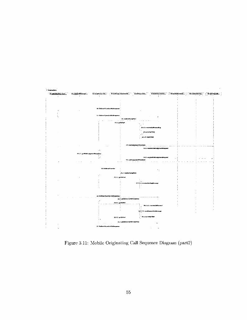
O interact ion!
r ^ ' e e < C r f a W W " q : « C « H - . ' ' '4» uet»fa|CjJMtBt8aqe:... ^ ^ 5 ; ; ; ' i : ' & mmPrray:•Ooiitrel"Mo... ' ^ccPrmvinCiao.. . ; ^ dfrftrtTjiiieContro™'. : !' & SBd'*Mfcii«Cii«t»,~ " i ' ' <&•$* " ' S f i j f f s i f a w f f l f r . :
10: txDtreetTtansfer&NxKespar
: 13: rBcetv&taniQPart
12 ,1 : getCcPart
13 .1 : recEiveHAHAxsiTn
13.2: receJweRABAsskpmentftequest
I S . ] : rfteetveRan^fiPart
15.1.1: a i tCtPar t
15.1.1.1: retehieAlerthgWcsMgB
16: RitDfrnctlranster&TiolespMBe ;
1 6 J : getDfrcctTi
15.1.1: t w t C t f J t
16.12: getCcPart
17: RiOSrert Transferal (Response
" ' I S . 1 .13 : itopTkner
Figure 3.11: Mobile Originating Call Sequence Diagram (part2)
55

After sending the ALERTING message to the mobile originating side, the MSC
receives a CONNECT message from the mobile terminating side. Once the MSC
receives that, it will send a corresponding CONNECT message to the CC message
proxy object, so the receive Call Connect operation will be invoked to indicate call
acceptance by the terminating side. Also, the CC message proxy object invokes
the send Connect Acknowledgment Message operation that sends the CONNECT
ACKNOWLEDGMENT message to the MSC to acknowledge the offered connection
[7], this sequence can be seen in events 16 and 17. More detailed information about
these events' operations and other sequence diagrams can be found in Appendices
A.l and A.2, respectively.
3.2.3 Mobile Terminating Call Realization
In this section, we present the mobile terminating call scenario realization that is
represented by the Terminate MS Call Use Case in the Use Case Model.
In Figures 3.12 and 3.13, we illustrate the basic flow sequence diagram of the
Terminate MS Call Use Case; it shows the participating objects and the sequence of
messages or events with numbers on them. This sequence diagram interacts with the
mobile originating call sequence diagram through the MSC to provide a complete
scenario of UE - UE call and to load the MSC consequently.
This sequence diagram is triggered and started by receiving PAGING request
message (RANAP message) from the MSC. In event 1 and 2, the call terminat
ing controller object forwards that PAGING request to the paging controller ob
ject which communicate with the RANAP message proxy through perform Paging
Request operation to understand the message elements. In event 3, once the call
terminating controller is indicated that PAGING request message has been received,
it will ask the Initial UE message controller object and the RANAP message proxy
to initiate the first message to be sent to the MSC, then the RANAP message proxy
invokes get Paging Response MM Part operation to ask the MM message to create
56

: » ic i lT i« i i fc taM r - &' paqlriqEBntrefe ... 8>ueTera*vt feCal . . . : I ^ranapProgys ^ctfrony:"C,„ 6 A M K I I ; " . -
1: perlormPagkigRequesf
3: paghtp tequeatRe iW
i: I M D M N V I I M ^ ^ v a ^ ^ m m * * * * *
3.1.2: getUeMassageflan^iParth
4 : fedXrettTransfer&toResponse
4 , ] : gatDrectTranferRespanse.
1.1-1; gstranHesponse
4.1.2: getMiftesponse
4 J : getDfcrxlTranferResfxxKe
J.l.l: getSeoritYModeCoinpletE
S: RxSeturityConimand&lxlt«f>onsB
9: RxOrect Transfer ftlirftexponse
ecetvcSetupMesgage
"3J: gctO*sc(tranlETflespanse
Figure 3.12: Mobile Terminating Call Sequence Diagram (parti)
57

the PAGING response message (MM message). This message will be sent to the
MSC to indicate that the required UE is located, the paging procedure is completed,
and the MSC can start contacting that UE [6] [7]. As we mentioned before, this
model provides the MM and CC message proxies to represent the UE or the mobile
station.
In events 4 and 5, the sequence of messages represents the authentication
operation that is required by the MM message proxy to authenticate the MSC and
calculate ciphering key; through event 8, the call scenario receives the IMSI for
the corresponding MM message proxy. Also events 7 and 8 illustrate the security
mode command operation to extract the encryption information and the integrity
protection information and to choose appropriate ciphering and integrity algorithms
[6].
In events 9 and 10, the mobile terminating controller forwards a direct transfer
message to the direct transfer controller which sends it to the RANAP message
proxy, this message will be forwarded to the CC message proxy. The receive Setup
Message operation will be invoked at the CC message proxy to indicate that it is a
SETUP message; this message is sent by the MSC to initiate a mobile terminated
call establishment. In this sequence, once the CC message proxy object receives the
SETUP message, it will invoke the send Call Confirmed operation to prepare the
CALL CONFIRM message; this message will be sent back to the MSC to indicate
that the SETUP message has been received properly and the incoming call request
has been confirmed [7].
In events 11 and 12, the RAB assignment controller object receives a RAB
assignment request message which contains the radio access carrier information;
a RAB assignment response message will be sent to MSC to confirm the radio
configuration. In events 13 and 14, the mobile terminating controller object asks
the RANAP and CC messaging proxies to generate an ALERTING message to
be sent to the MSC; this message indicates that the alerting procedure has been
58
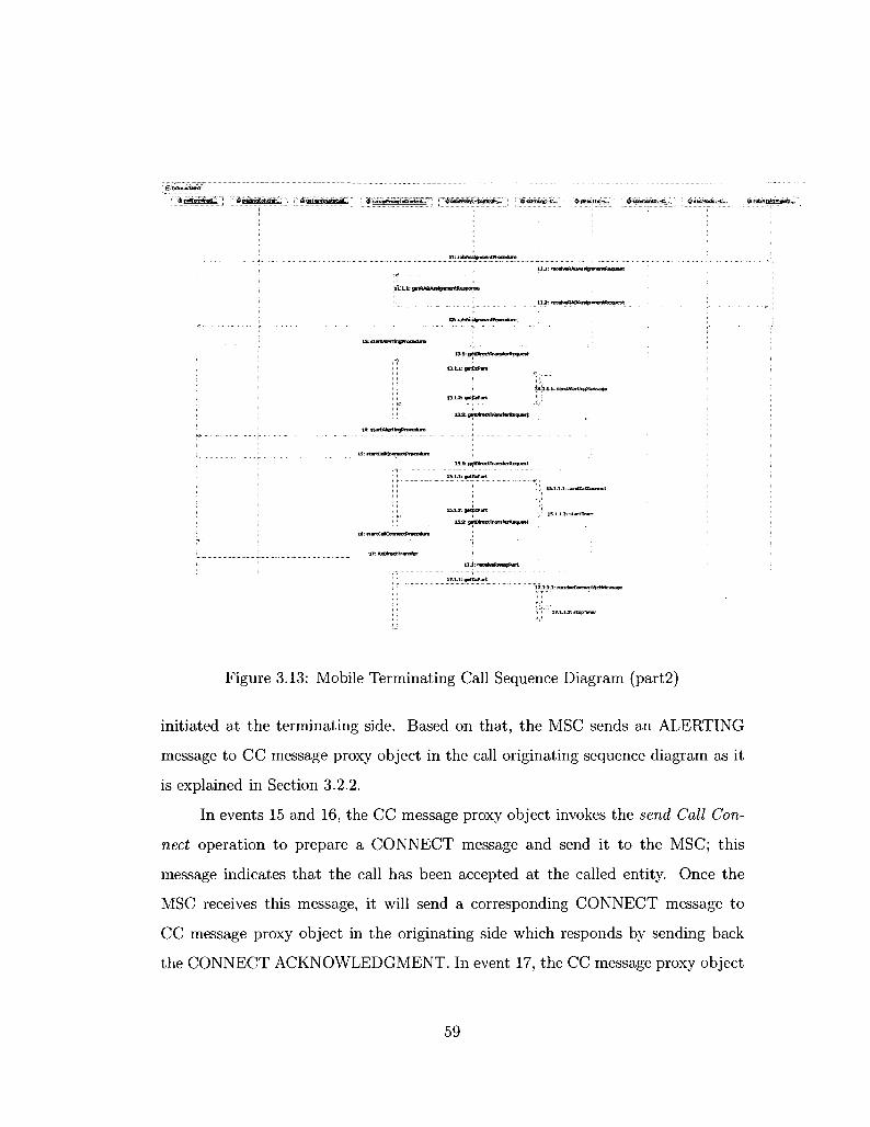
11: rabAsstgnrnenmucedure
11.1:
12: rabAsstgmnentProcedun
13.12: gBt&Part
laa-. geoNr«cU>
15.1: getDfretlTransferRevut
15 i J : gutCePart • , 15-1.1.2: etartTinier
152 getUrectIransterRe<|uest
17: toatrecnransfer
Figure 3.13: Mobile Terminating Call Sequence Diagram (part2)
initiated at the terminating side. Based on that, the MSC sends an ALERTING
message to CC message proxy object in the call originating sequence diagram as it
is explained in Section 3.2.2.
In events 15 and 16, the CC message proxy object invokes the send Call Con
nect operation to prepare a CONNECT message and send it to the MSC; this
message indicates that the call has been accepted at the called entity. Once the
MSC receives this message, it will send a corresponding CONNECT message to
CC message proxy object in the originating side which responds by sending back
the CONNECT ACKNOWLEDGMENT. In event 17, the CC message proxy object
59
receives the CONNECT ACKNOWLEDGMENT message by invoking the receive
Connect Acknowledgment Message which indicates that the CC message proxy has
been awarded the call [7]. More detailed information about these events' operations
and other sequence diagrams are given in Appendices A.l and A.2, respectively.
3.2.4 Traffic Handling Realization
The Handle Traffic and Distinguish Call Scenarios Use Cases plays an important
role to handle the traffic in the Traffic Handler component.
The Distinguish Call Scenarios Use Case is realized through the the Distin
guish Call Scenarios sequence diagram, this sequence is responsible for receiving the
call scenario requests -that are forwarded by the RANAP Controller component- to
deliver each of them to the right call scenario controller object to initiate the re
quired call scenario or sequence, also for each new call scenario request, a connection
ID will be generated to keep track of the call scenario messages. These call requests
are originally initiated by the RanapSim Manager Actor.
The Handle Traffic Use Case is realized by two sequence diagrams one of them
is the Transfer to Handler sequence diagram, this sequence is functioning to receive
the signaling messages from the RANAP Controller component and forward them to
the running call scenarios that are interacting with the MSC through the RANAP
Controller component. These messages will be forwarded to the right destination
based on the connection ID for each call scenario. The other sequence diagram
which realizes the Handle Traffic Use Case is the Transfer to RANAP Controller
sequence diagram, this sequence explain how the generated messages from the call
scenarios can be forwarded to the RANAP Controller component through the traffic
handler controller object.
In this section, we present the Distinguish Call Scenarios sequence diagram
which is shown in Figure 3.14. In event 1, this sequence starts when the traffic
handler controller object receives a call scenario request through the Call Scenario
60

^ trafficHandllnqConiroller,., 6 locatlonUpdateContr..
. 1 : callScenarioReq
" ^ ^ i f # tg i ^h j k ^» B 1 P"" ^aiJTCThVfe^^cM^Htf!^
[callScenario - - LocationUpdale]
1: generateSuggestedConnectlonld
2: locatlonUpdReq
I [cal (Scenario == MsCel (Originating]
.; 1: generateSuggestedCormectionld
2: mobflebrtgReq
[callScenario == OrigCal (Disconnect]
1: transferDisconnectCommartdTcMobOrigSini
2: transferDisconnectCoiranandToMobOrigSim
[callScenario ==; TermCallDisconnect] 1: transferDisconnectCommandToMobtermSIrn
2: IransferOisconnectCornmandToMobTermSIm
[else] 1: scenartoIsNotSupported
Figure 3.14: Distinguish Call Scenarios Sequence Diagram
61

parameter, as explained in the diagram, the traffic handler controller object uses
alternative combined fragments (switch condition provided by UML 2.0) to iden
tify the received call scenario request [4], this switch condition provides blocks for
different cases.
In the first block of the switch condition, the call Scenario will be checked
whether the request is location update, if this the case, the location Update Request
operation will be invoked to initiate the call and the generate Suggested Connection
ID operation will be invoked to generate a new connection ID and connection ID
state to be attached with all messages that are related to the initiated call scenario.
The new connection ID is indicated by the SCCP Connection ID data element, and
the new connection ID state is indicated by the SCCP Connection Id state data
element which holds the "generated" state, more details will be given in Chapter 4.
The second block does the same for the mobile call originating, so if the request
is to originate a call, the mobile originating call scenario will be triggered. In the
third and forth blocks, we explain if the call scenario request is to disconnect the
call on the mobile originating side or disconnect the call on the terminating side,
consequently, a corresponding sequence diagram will be initiated to disconnect the
call. Since the mobile terminating call is initiated by PAGING request message from
the MSC, so there is no call scenario request indicates a block for the terminating
call scenario. More detailed information about these events' operations and other
sequence diagrams for the Traffic Handler component can be found Appendices A.l
and A.2, respectively.
3.3 UML Class Diagram
This section describes the static structure of the Traffic Handler component by
illustrating the class diagrams. In this context, a class diagram helps to understand
the requirements of the Traffic Handler and to describe exactly how this component
62
works. Furthermore, a class diagram defines the relationships between classes and
illustrates the structure of the model by using attributes, operations, signals, and
interfaces. Also, it shows an inheritance hierarchy among classes [1].
In class diagrams, we use interfaces to facilitate the job and give more details
about the classes relationships. Interfaces are model elements that define sets of op
erations that other classes must implement. We can use interfaces in class diagrams
to specify a contract between the interface and the class that realizes the interface.
Each interface specifies a well-defined set of operations that have public visibil
ity. Those operations will be provided to another class through a dependency/use
relationship [4]. In UML, we call this relationship between the interface and its
implementing class interface realization relationship. In next sections we provide
the class diagrams for the Traffic Handler component.
3.3.1 Location Update Class Diagram
We describe the class diagram for the location update call scenario that is provided
by the Traffic Handler component, Figure 3.5 shows the UML representation for this
class diagram.
The location update class diagram contains all classes that participate to gen
erate the signaling messages for the location update call scenario, also it consists of
some interfaces to handle and explain the relationships between the classes.
From the class diagram shown in Figure 3.5, the Location Update Controller
class uses the IRanapProcedures_LocUpd Interface through a dependency/use re
lationship [4]. This interface is implemented through an interface realization re
lationship by the Direct Transfer Controller, Security Mode Controller, Common
ID Controller, and Initial UE Message Controller classes. Those classes use the
IRanapMessage_LocUpd Interface which is realized or implemented by the RANAP
message proxy class, through this interface, the RANAP message proxy class is able
to specify the required operations to provide them to other classes.
63

«Contrcto. 4$ LocationUptlateCDnlraMef
; r^UserData j : '"^to<att)riUix«eq() i l&traSferttesageToLreationUpdSim ( ) ;
«yse»
^'interfaces ' ;
r ^ r t S o ^ a t o n U p d a t e ()" j .CoommlDoflMSI ( ) : ^RxCfesctTrarsferSTiResponse ( ) ; ^FtaSecuttyCommand&TxResponsB ( ) ;
• «Gonbcrf», • • ' <& MrmTrariftrControHer
'{jj| Ribir'ectf ransfer&txResparise ("). ^statCaBCorinacrPracedre ( ) ^sUrtAtertuProcedure ( ) ^startCaflOeaiingProceduet ) gj^RsDirectTransfei ( )
«Ccntrobl ^ SecurltyModeConlroRer
1 ^RxSecwtyCcmmandSiTxRespbnse ( ) i ' "i^CcBwnahlDofiMsj' ('")'
iaContiote ; $ InitialUBIessageCantroller
:'^siartLbtatio«*tJdatV'r) : ^startcalcwglrating ( ) • gg, slarKaTTenTM-iatriQ ( )
«mterface» ' .
r^'(»'tUeMessao*arapPar't''(')' \ §^ gelDiettTranferResporee ( ) I ^getSeojityModeConfilete (.) \ ^.pertcrmCommonlDQnfianap ( )
-^Controls ^ MobtBtvMarwgmeTrtMessaQBPioxy
"MTW^Z '""~"Z : ^getLocUpcRei3*iP*t ( ) ; ^getWrfiesptinsB ( ) j ^euthentcatiorfiBactJWi ( ) : ^gBtOnServteRetJflmPart ( ) ; g^recelvBWnPart ( ) j ^ s t a t T m e r O = ^s topTrnet ( ) j ^getPagingRespanseWnPart'f.) j ^ reteassMMcomactjon ( ) j ^PBrfarmCmSeiviceActepted ( J
^ pBrforrriCmSeimceRejected ( ) • ^receivBAuthenticalianReguest ( )
g j , receivetocatJonOpdateAaiept ( ) : ^recavetacatkxHAjdatefte) ( }
%JMobManagment„ioct>pd
• ^Qei iKiJpiateci*nPart"() HgetWnResponse ( )
. ^lotatiDnUpdataAccept ( )
mobltYrnanagmentmessaospioxy - ranapmessageorcKy
aConlrot" & RanapMessageProxy *
; ^ ^ t U ^ t e s s a g e R a r a p ^ t l ' ' ) '• G& getDeecITfanferResponse ( )
. ^getSecurttyModeCoFT(fete ( ) •• ; $& perfornCommonlDonRanap ( ) : i %rrceiveP.anaoPart i > ; <f{j, get Dree tTrarsferRequest ( ) \ <[^receiveRABAsswT19nWequest (): ^getRABAssignmentReqxnse (>
i ^,pertoimSecW3tJeCdrfmad ( ) %perforrfiluReIeaseCQnimarKt ( ) '
.^perfarmluReleaseGxnplete ( ) g§,performPagngReqii8st { )
Figure 3.15: Location Update Class Diagram
The RANAP message proxy class uses some operations from the Mobility Man
agement message proxy class which provides these operations through the IMob-
ManagmenLLocUpd Interface. The RANAP message proxy class has an associa
tion/aggregation relationship [4] with the MM message proxy class with (1 - 0..1)
multiplicity. In this context, this notation means that one object of the RANAP
message proxy may have zero or one object of the MM message proxy. Based on the
used RANAP procedure, some of the RANAP messages may have a MM message
inside. More information about the Interfaces in this class diagram can be found in
Appendix A.3.
64
3.3.2 Mobile Originating Call Class Diagram
The mobile originating call scenario is provided by the Traffic Handler component,
and we have presented the classes and the Use Case realization of modeling this
scenario. In this section, we present the class diagram for the mobile originating call
scenario; Figure 3.16 shows the UML representation for the mobile originating call
class diagram.
This class diagram consists of all classes that participate to originate a call
and consequently generate a signaling traffic for this call scenario, also several UML
interfaces and relationships have been used to show more details about the classes'
communications. From what is shown in the class diagram; the main class for this
scenario is the Call Originating Controller class which has a dependency/use rela
tionship with the IRanapProcedures-MobOrig Interface to use the interface provided
services. This interface is implemented through an interface realization relationship
by the Direct Transfer Controller, Security Mode Controller, Common ID Controller,
Initial UE Message Controller, RAB Assignment Controller, Iu Release Controller
classes. Those classes are having some messaging data services through using the
IRanapMessage Interface which is realized or implemented by the RANAP message
proxy class, so the RANAP message proxy class specifies -using this interface- the
required operations to provide.
The RANAP message proxy class interacts with the Mobility Management
message proxy to use some operations that are provided by the MM message proxy
class.
The IMobManagmenLMobOrig Interface is implemented by the MM message
proxy class through the interface realization relationship and used by the RANAP
message proxy class through the dependency/use relationship. The same thing will
be applied for services that are provided by the call control message proxy class
to the RANAP message proxy class, the ICallControLMobOrig Interface will be
implemented by the CC message proxy class, and used by the RANAP message proxy
65

. «e«nbd» "/"". & CallOriginatingtontroIef
H^NAS-POU ~ - • ' -
^T)<C»ectTr^feMj*espdnse' '( )
SgtiansferMessageTGMabOrigSrn ( ) ^trar^castBnrKCtCorTrwTdToMntCri^lm { ) ^setStcpConnectiortidStoeToBeDtoomected ( ) :
§IRampProcedurBt__f*tobQrig \
Implements
Implements
^.StfftCdOriQnatho < ) {^FUpjectTransfer&TxResponse ( ) ; ^RKSeaJityCorrmand&TxRespo... g^CommonlDoflMSI ( ) ^rabAsstenrnentProcsdiie ( ) ^,FUI»ectTfaTsfe»() ^startCaKearlngPfocedure ( ) ^iuftetaasePracediie ( )
8j^ waonafcc tmservieeResMreeO fy*a&vti> startSstLpftocectureO
^ SetuttyMoileCantroBa'
' ^"RiSBairitvCwnTar^txte'.. '!
<& DlrectTranferCoritroler
\ ^ReiDtectTrarefeiSTxRespO... i ^ startCdCorrractFracedure.,. \ ^startAlertingftocedure ( ) \ %starttaKleartrigftocedure ( ) !^Rxt»ectTrSnsfei ( )
«Cbr«fd» A RABAS5lffw>ent
I ^st»tLocatoiUpdate ( ) l i f . * *??8™^!*? . - : -J ! ^startCalOriginaang ( )
I ^statGaffTeimruting ( )
' ffCcntrot* ^ iuReleaseControfcf
^;lLSeteai€Procedure.()
.; --Witerfaee* " *5 IRanapMesMge
n i ^receftfefianapPart ( ) \ gjjgetDirectTrsnferResponse t ) \ g|p9iftB7nCamnwTiIDanRanap ( ) i ^BStffceetTtansferFequest ( ) I ^ receweRABAssigrinientRequest ( ) i ^ j perframlufteleaseCainnvgnd ( ) I ^perfbrmSecModeCommad ( )
•':-. ' 'fy&reji&ii '••'•' AMobatyManapnentMessage I * * Proxy
%T^30 ih ^getLocUp*aqMmPart ( ) g^getMmRespanse ( ) {^authenticattonReacticn ( > g^getCmSeiviceReqOTnPat ( ) g&recelveP+nPart ( ) (jj£startTim8t ( ) g^stopTlmef ( )
{^Q8tPa$"iQRssoonseMmPaU ( ) g^ieteaseMMccirtnecticn ( ) gijperfamCmSerwiteAccepted ( ) {J|J.psrfamCnS3vtceftejectBd ( ) ^lecEreAuthentKationRequesi ( ) ; ^recefcetocaJtanUpdateAccept ( ) . j^iecettetoQticnUpdjteRej ( )
«3 JWtoAMflfi^ewierjt.;. i : :a MottOrig
^getemSerwceRetfi... ^recewedtnPart ( )
" mob&tyrnana^TOntmessagepro>iy - ranapmessageoroxy
«eoritfoto % RanapMessageProxy
$|,getUeMessageaanaoPart ( ) ^gBtOrettTrarrfBrResponse ( ) ^getSecurityModeComptete ( ) ^perfomiComrnorilDonRariap ( ) ^FeteiveftanapPart ( ) (•^getCfeettTransteRGquest ( ) {ji^receiveRABAsjJgnrnentReQuest [) j ^getRABAsagnmentBespo^se ( ) ^pafonnSecModeCommad ( ) g^peffDTTTiIuReteaieCommand ( ) ^pefformluReteaseComptetet ) ^petfbrmPagsTgRequest ( )
oliterface* MistartTimer
-•'[ jg , nsiyiafco stiatTmn»3036
,..,«Ht er'faCe»
\ ' ^ reteaseKwiibnnet.'"'."":
• Implements
: «ihterfape» • ' " «Cohtrdfe> ; •^ICaKdrrtraLMob \ : & CaUControWessageProxy i ':..... °^ ^ T 3 0 3 '
: ^ • ~ t fT310 ^ST313 $% start Timer (1 ^get tcPar t ( ) i^prepareSetupMessage ( ) S^Jiec€weCa*Jiixeedng ( ) ^.stopTimer ( ) ^wndCalConfrmed [ j ^ sendCaKonnect ( ) g ^ serdAfertmgMassage<) ^recelveAtertlf^Messags (') ^reteiveCaKonnect { ) &# sendCcmectAd<Me5S3ge ( ) $& receiveSetupMessaoe t )
i rarwpmessaBepriBy - cafconaolrnessaoeproxV^recavaConnectAckMessage ( ) j '^sendDlsconnectMsssage'f)
O ^sencReleaseComctete { )
Figure 3.16: Mobile Originating Call Class Diagram
66
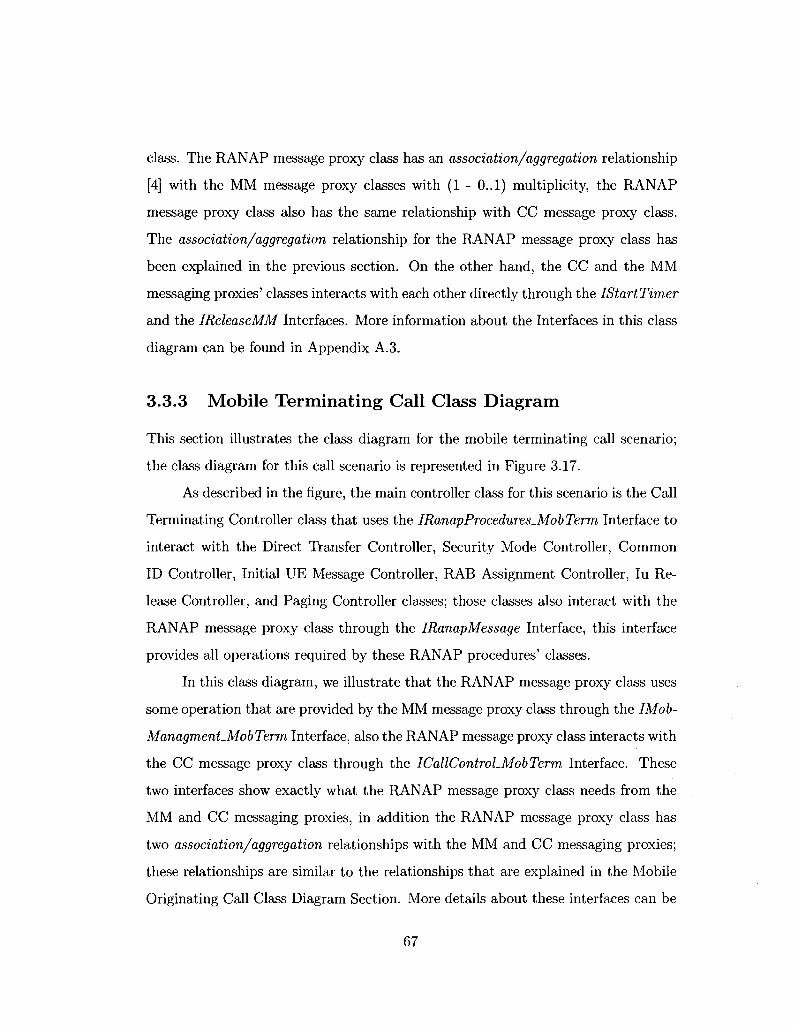
class. The RANAP message proxy class has an association/aggregation relationship
[4] with the MM message proxy classes with (1 - 0..1) multiplicity, the RANAP
message proxy class also has the same relationship with CC message proxy class.
The association/aggregation relationship for the RANAP message proxy class has
been explained in the previous section. On the other hand, the CC and the MM
messaging proxies' classes interacts with each other directly through the IStartTimer
and the IReleaseMM Interfaces. More information about the Interfaces in this class
diagram can be found in Appendix A. 3.
3.3.3 Mobile Terminating Call Class Diagram
This section illustrates the class diagram for the mobile terminating call scenario;
the class diagram for this call scenario is represented in Figure 3.17.
As described in the figure, the main controller class for this scenario is the Call
Terminating Controller class that uses the IRanapProcedures.MobTerm Interface to
interact with the Direct Transfer Controller, Security Mode Controller, Common
ID Controller, Initial UE Message Controller, RAB Assignment Controller, Iu Re
lease Controller, and Paging Controller classes; those classes also interact with the
RANAP message proxy class through the IRanapMessage Interface, this interface
provides all operations required by these RANAP procedures' classes.
In this class diagram, we illustrate that the RANAP message proxy class uses
some operation that are provided by the MM message proxy class through the IMob-
Managment_MobTerm Interface, also the RANAP message proxy class interacts with
the CC message proxy class through the ICallControLMobTerm Interface. These
two interfaces show exactly what the RANAP message proxy class needs from the
MM and CC messaging proxies, in addition the RANAP message proxy class has
two association/aggregation relationships with the MM and CC messaging proxies;
these relationships are similar to the relationships that are explained in the Mobile
Originating Call Class Diagram Section. More details about these interfaces can be
67
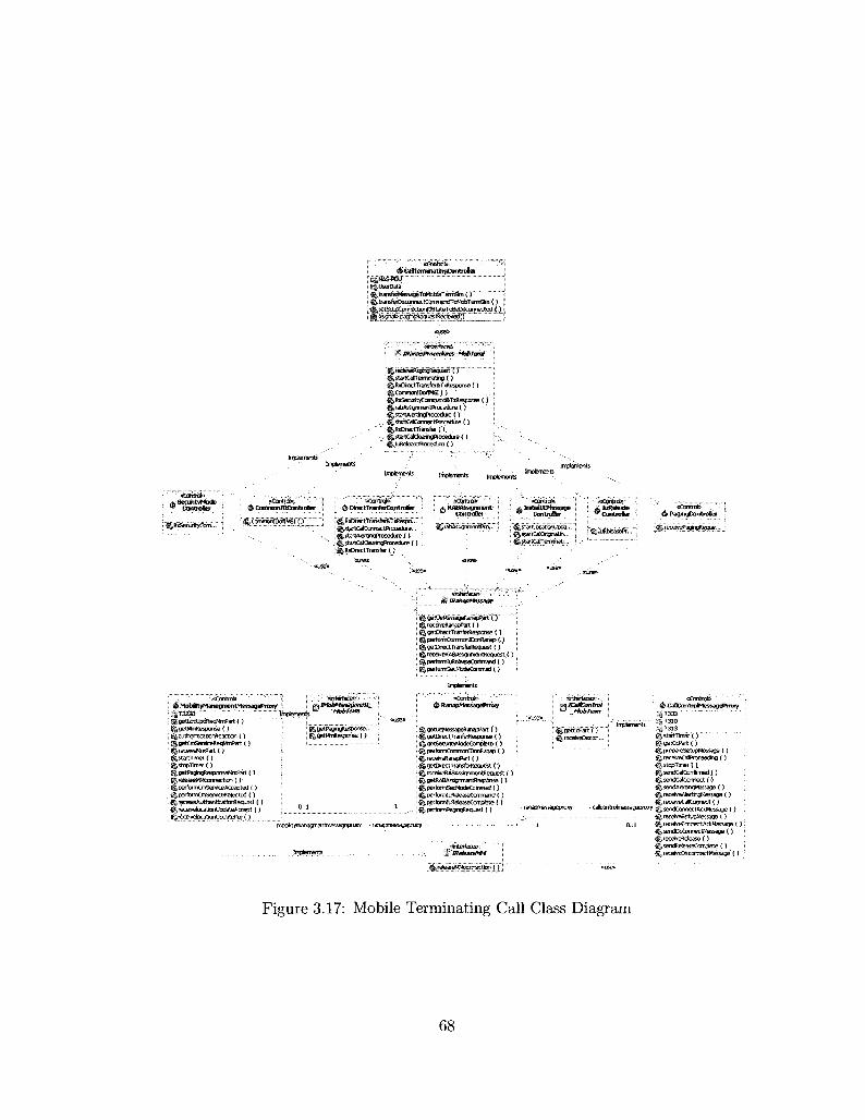
!• ^CaStem#tatingContrDiler i l $ 'NSs«> i i ; £§,UserDatai r^'tian^^i^liMMefariSm(^ ; ^transfat!6qOTi«tCormien[^oMc6Te»man (•)
tsetSctpCprriectonldStatefcBeOstannecterf f)
M Etmas>PTacexfures_MobT&m
i {^startCalTenrtnaaTg ( ) ; J^RxDiractTrarBtei&f)iREgjareB £) : ^CcmmorUDoffiei {)
i g^rabAsstgnmentProcediie ( ) . : ^startAtertingPtoced^e ( )
•}. % StaftCalCoiTnectPrEJceciJe ( ) \ ^RxDtectTfansfet (')', .: gjiStartCaHdearngPtocedue ( ) " - - ' - • - • B ( )
kSedir i tyHbde 9 .Cohtrplter % CommorilDCtvitroSer
' ^Cnrnmonn^ 'MSn") " ' '
% DijertTrarfWControter
' g|R »DiecttiafisJHat xRespa."" ^ startCalCDmec tftacedue... ^startAtertngProCBdirt.{) g&startCalCleart-flProcedLre ( ) . Ij^RsDrect Transfer ( )
& RABAssignment » ControBer
£ raMi'dgnmentPra'.'.' ; ^rtartCaflOrigriatih... ! {j^startCaffTermfriatU
I ^ bRefeat t ^Con t roDw
r^IUREteaseRr",.;''
«Contocfe> ^ PagingControSer
^ iftanapMessage
'•' .... :.«Contrate' 1 i ^ MtibtftyttanagmentMessageProxy5 \
/getLocuiwSleqri^art I j g^gBtMTflesponse{ ) ^authentjcatjorfteactlcri ( ) g|oetOnSefvfceft«*»nPart ( ) ^teceiveWnPat ( ) ^startTimei ( )
' ^s topTlnsr ( ) g~getPagintflespanseWTtPart ( )
= ^reteaseMMcoreiectKjn ( ) ; ^perfoimCmServiceAccepted [ ) ,' S^performCmSefWKeR ejected ( ) : ^receweAuthenticationftequest ( ) ^recefvelocatlonUodateAecept ( ) ^rereivelocatimUpciatGftej ( )
*' MobTerm
. . r n ^recetveRanapPart ( ) ^getDtectTianferttepcree ( ) ^perfonTitQmmonlDoriRanapQ % getDirectTransfetRequest.() ^leceiveRAeKssignmentflequest ( ) .' ^perfoftriltReJeaseCofiTnand ( ) {^performSecModeCommad ( )
Implements
& RanapMessagePmxy
^getUeMsssageftartapPart t ) ^getQrectTranferRespanse ( ) ^getSecurityModeCOmptete^) ^perfDrrnCoamcnlDonRanao ( ) %rece*vefianapPart ( ) {g^getDrectTransfeiRecBJest ( )
^getRflBAssignmeritRespcnse ( ) ^performSecModeConwnad ( ) ^petformluReteaseCoiTHTiancI ( } %performlufteleaseCofnptete ( > ^performPagngttequest ( )
• moMtynwwgnrantmessageprCHy - ranapmessageprtiSy ••
gUeieaseMMccnnectiort ( )
OTiterfacBSf'.. mJCaSControt 5 3 _MobTatm
IgettcPart 'O" % rec9V6Co£Con.
Implements
• ranapmessageproxy
& CafflT-nrrtroMessagePTOxy ; i ^T303 | EST310 &&T313 §& start Timer ( ) > 0jigetCcPart-( ) > SJ^prepareSatupMeKage ( ) <^recehraCa!Proceedfrig ( ) $1. StOpTBTEt '{ ). ^sendCaKonfrmedO ^sendCalConhect (=) igjserxlAtertingMassage ( ) ^rBcetvaAtertb-igMBssage ( ) g^recerfeCailCQnnect ( )
cafcontrokTiessaoeprDXY ^sendCorriectAckMessage ( ) . (& receiveSstupMessaga ( }
0..1 ^leceweCcrmEctAckMsssage ( ) : ^sendDfccorrrectP'tessage O SgjieceiveRetease ( ) ^ sendReteaseComptete ( ) ^leceireOscorinectMessage (> :
Figure 3.17: Mobile Terminating Call Class Diagram
68

found in Appendix A.3.
3.3.4 Traffic Handling Class Diagram
We describe the class diagram for the control functionality of the Traffic Handler
component; Figure 3.18 shows the UML representation for this class diagram.
«Cbrrtrc4» 6 TraffitHandfingControDer
it^UserData &^ sccpGomectonldStatePtr !%sccpGorrieatjonldPtr %caBScenaritfteq.O {§£ Qena-ateSuggestedConnffitiaild i). %ttasfWMessaoetoHancBer ( ) f^ tdenefyMess^STyps ( ) jg|messa^IsUnknown (>:
^ ' tofcnOtxSieq' i ) : ^b-aisferMessagBTtlocationLtodSlm'() gjJ,mobfeOrigReqi)
: ^ , transfBrMBSsagsToMobOrigSBTi ( )
gl.tffflTsferMessagsToMotrfeTa'man ( ) : ^ti3nsfErDiscorffiatCCTnmardTt*^TermaTi ( )
«tbritro!»-^ LocattonUpdateControfler
: L^UserOata
^tatationUpdReq ( ) ^trasferl^ssageTctocafiortJpdSim ( )
# CaBOtfginattncpbtrtroner
SgUserData.
^Ti^^fraf^fer&RxRKpcrce"(J [ HmobileOriaReqC) I $& trarsferMessageToMobOrigStm ( ) { |§. trareferKsconnectCciTimsTdToMobCSIgSm ( ) < ^setSccpCttmectcmlctStateToBeDiscomectKl ( ) I
«Cbrttro& & CafTermtoathgControfler
£^NAS-PDU~~ " " ^UsetOata ^transferMessageTc^tatSeTamSfrn.() ^bansferDreorv^tCdmman^ ( ) ^setScxpCor8Tectbrdi£tateTo6^>sa3rract8d ( )
i;j nrarisferloHandfer
; fransferTtessa^TcWareCer ( J" j'
Figure 3.18: Traffic Handling Class Diagram
The class diagram shows the Traffic Handling Controller class uses services that
are provided by the controllers' classes of the call scenarios through the ICallScenario
Interface; the Traffic Handling Controller class has a dependency/use relationship
with this Interface as illustrated in this Figure. The ICallScenario Interface is
69

realized by the Location Update Controller, Call Originating Controller, and Call
Terminating Controller classes. On the other hand, the Traffic Handler Controller
class implements the ITransferToHandler Interface that is used by call scenarios
controller classes.
3.3.5 Traffic Messaging Class Diagrams
The Traffic Handler component provides models for call scenarios to generate signal
ing traffic, the control classes for each call scenario model should interact with the
messaging proxies' classes to handle the request and create the required message.
Those messaging proxies are; the RANAP message proxy, the Mobility Management
proxy, and the Call Control proxy classes. Next, we are going to present the class
diagrams for those messages.
R A N A P Message
The RANAP Message class diagram shows the several types of RANAP messages
where each one is used for specific service; Figure 3.19 shows the UML representation
for the RANAP message class diagram.
This class diagram shows different types of RANAP messages classes as En
tity classes, these classes are; Direct Transfer, Initial UE, Common ID, Security
Mode Command, Security Mode Complete, RAB Assignment, Paging Request, as
well as Iu Release messages' classes [6]. Each one of these classes has an associa
tion/composition relationship with the RANAP message proxy class with (1 - 0..1)
multiplicity [4]. This relationship indicates that those messages classes always be
long to the RANAP message proxy class. The multiplicity (1 - 0..1) means that one
object of the RANAP message proxy may own zero or one object of each type of the
RANAP messages' objects. Through this relationship, the RANAP message proxy
class is able to access the messages' classes through its operation. More information
about these classes can be found in Appendix A. 1.1.
70
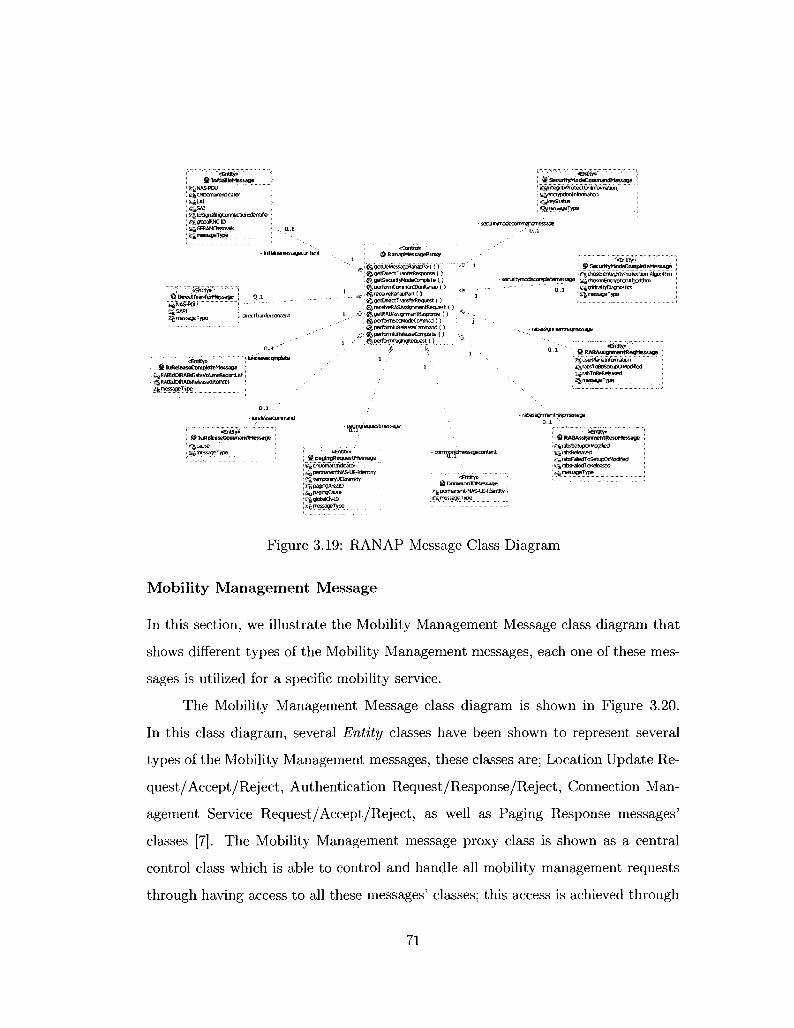
m InftfcdUeMessage g^NASTOU 1 ^CNDomaMfMJtatof ' ^ L W { Q S A I ^luSgnatogCornectJonicteritifer;
££.<SRANCIassmark ., o. , j •-gmessageType
& Di re t tT fanteMBMa^ j 0 ,4
:- cftetttranfereortferit
e£rtt«Y» ' • ' • ' . S luReteaseCompteteMBSsage
; ^RABldOKABsReieasedltemiEs • £j|messageType
'} fciefeaseccmptete
0,-1 -
- uete'asefcomroand
«ContrcJ» & RanapMCssageProxy
u ^ r ^ g e t i J f e * ^ a ^ f i a h a p P a r t ( " ) """! ^ getDtectTranferResponse { )
; ^getSecuityHodeComotele ( ) | ^ performCommmlDonRaTap ( )
. ^ ^recaveRanapPart ( ) " ! g£ QetttectTraraferRequest ( ]
:• ^ , receiveRASftssiyimantReaijeit { ) , .#1 (& getRABAssignmaitRasponse ( )
j ^perfcrmSecModeCornmad ( ) ! f ^ perfamluReteaseCttmiand ( )
ffi 6§, pertomliiteleaseCamptete ( ) ]ft§ perfbrmPagfrigRequest ( )
- pagjpgreouestrnessage
«&ttity» ' • ' • " > § ! SecurityModeCommandMessage !
\ ^emypUonltifbrmatlcri : s^keyStatus ; &g,niessageType
• seailtymodeccxTmandmessage
-a£ntity» fat SetinttyModeCompteteMessage
;& chosenlrrtegrityFiotectbn Algorithm - secuitymodKompieterTiessagB | ^trw9B*nayp1ionAlgOTlthm
t£ntity». @ paglngRequestMessage
- ^ cnDomaiilndcator - a petmanentNAS-LC-IdenM y ^ temper aryUEldentity ».MpagaTgAreaiD -sPagingCause ^.gbbaCN-lD
,fcmessageType
c ofr¥nprt*nessagec ontent
«EhtIty» @ ComnionlDMesaage
^permanerW-NAS-ce-Identrty i g message Type
^KOrttaltyaaonostlcs ^messageType
- rabasSgnmentreqmessage
«Ertttj»'.,
i£fj userPlanelnfbnTBUDn -£g rateTceeSetifjOrMoctfted »'& tabToBeReteased ikgmessageType.
- rabasSgnmehtrespmessage
«% rabsSetLpOrModffed S 'rabsReteased ^ 4 rateFatedToSetuDCrModflec)
Figure 3.19: RANAP Message Class Diagram
Mobility Management Message
In this section, we illustrate the Mobility Management Message class diagram that
shows different types of the Mobility Management messages, each one of these mes
sages is utilized for a specific mobility service.
The Mobility Management Message class diagram is shown in Figure 3.20.
In this class diagram, several Entity classes have been shown to represent several
types of the Mobility Management messages, these classes are; Location Update Re
quest/Accept/Reject, Authentication Request/Response/Reject, Connection Man
agement Service Request/Accept/Reject, as well as Paging Response messages'
classes [7]. The Mobility Management message proxy class is shown as a central
control class which is able to control and handle all mobility management requests
through having access to all these messages' classes; this access is achieved through
71

j @ AuthenticationRK^tessage :
! ^ajthe^aticryiequestMessage.'.. \ s:gc()heifrigKeySeqLienceNLm±ier | £&spaeHatfOttet j sgautrenteatioriParaTieterfiAND ; ii^protocoOstrimriatpr
- authentfcattonfeqmetsage
@' ALrthentteatiorRejMessage '• ^authOTtfcatoiRe^tMrasagef... j i^Df0tocaDscrin*v3lc» \ -
} authenticatlcreejmessage
M. AuttrentfcationfiBsrtessage ^authenOcatlonRespqnseParame...
, 3^aulhentcattor*esp»isBMess3g... - authentfcatonrssmessage
.:- toe alwTUDdateaccephnBswgB
<§ LotatlonUpdateAtceptMessage I'
' 's^ ' tacat i^ '^dehPftatton" : ^localciriUpdafngAcceptMess.jgeTvpe I SjjjDfOtocDlDtsafrntTator g&skfclndfcata
«£ntitY*> @ CmServireAcceptMessage
^ari tovtef l iceptMessaoetype I £& protocoOsolmnatot £& skplndcator
- cmsaviceaccepi itmessape
*CGntK*» ^MobBtyMww^rtentMessageProxy ;
^ 'ge tLbdJp*e i *S f *a r t (") ^OBtMrrfiesponseO. g|authen«ataiReactiori ( } {f^getfrnSeMceRecHmPart ( )
^startTtner ( ) : %StOpTfTW < ) ^9etPa£frT#esporeeMrr*>a't ( ) f^rebaseMMccrine<tion{} §^ perlbimCmServlceAccQpted ( ) ^peiformQriServfceRejectett ( ) ^ t receiveAuthenttatiDnRequest ( ) fi| receMocattonupdateAccept ( ) - • ' • - - - • - » < )
«£ntityi> @ CmServtteReJMessage
* 'ijsj cmSefYiceRejKtMessa^type - cmservicerejmessage : ^ r e J e i : t cause
% pratocotHscrlrrii-tator 0 , 1 ^ . ^ n * * ™
«erttltyj* @ Cm5ervkeRe<*>tessage
CTgcmServiceType ,. ^ prDtocoOscrtnlnataf igsJtpIncfcatcf - gCpherngKeySeGuerrceNurrbsr .- moMeStaOGnOassmark iSmobieIdenmy
- Iocationupd3tereqme$$4ge
- (ocdtbrufjdaterejrressage
«&rtftv» '< @ LotatlonUpdateRelMessage
: K^to«OortJpdatrt^ejectMBsageType
: SgprotocdDiscTimhator : ^askplntfcatcw
- pagingresponsemsssagecontent
• «Entfty»
! • : £§ pagfrxf esoonseMessageType I ;£gspareHatfOctet • < ^ protocoDiscnnrriator
Sg mobteStdtinCbssms k ji^mobBteldantity
ig , bcarrmUpdatingRequeiiWessageType ;
. .^JocattrWcdateiaType Z§ beat ioiAiealdRrilifc ation ^-^ mofaleStatlonClassmartrFaUMTS i & protocoEtealrTtfiator .j^ddplndcatu iigttJheraT^CeySequsncefcfumber £§ moWeStattonaasunark ^mcfoteldentity
Figure 3.20: Mobility Management Message Class Diagram
the association/composition relationship with (1 - 0..1) multiplicity [4].
This relationship indicates that the Mobility Management message proxy class
always contains the mobility management messages classes, and the (1 - 0..1) mul
tiplicity indicates that one object of the Mobility Management message proxy may
own zero or one object of each type of the MM messages' objects. More information
about these classes can be found in Appendix A. 1.1.
Call Control Message
The Call Control Message class diagram shows all control and entity classes that co
operate to build the call control message; Figure 3.21 shows the UML representation
for the Call Control message class diagram.
72

<^nffl¥» fi> SetupMessage
L^setupMBssageType £§catedPartyBCONLffrb« :
£^caBngParty5ii>address: K^cafedPartyStb-address j i£gcaBng?artyBCIMurt)er • (wyProtoceffSsCTirSetor [ L^transacticnldentifiBr \ L^stfeamldent)fl» P " - , ? " x
{BfibevacapaMhr- , . ^ tupme^ags ' c^sipDortedCodecs
'«Btfity»' ' #MerbngMessage
^atertfngMessageType 0 * .^facffly i S&user-user j , ajstjngmessage * & progtesslndtator -g protocolDtsoimnator-s§ transactionldentifier
0 . . 1 , . - - ' '
- . . . 1
^ 1
'"*®i
1 . , ^ '
«&rtfty> . „_ t C a H P r o c e e d i n ^ t e s s ^ ^iproceedingmessagG
i ^ cafrVoeeedfric^teSsagBType ^teararCapabffity
^prDgressIntfcator 3^j protomDreoiTTinatoi
s trahsac'ttonidentffier — i
o£otitjo$ ^ CaflContToWessageProxy
SJfcTSM
^start faf ier ( ) ^getCcPart { ) g j , preparasetifiMessage {') |^receiveCaS\oceedng ( ) ^ s t o p T n e r O ^sencJCaTConfirmed i ) (ij^sendCaKonnect ( ) ^sendAJertlngMassage (.) g&rec©iv8Aiertingwiessage ( ) g^recerneCaflCcnnect (.) ^sendConrteclACkMessage ( ) g^reeeiveSetutftessage ( ) g^recelveCcnnectAckMessacje ( ) {^sendDBcarcnectMewagB ( ) {^recetvsRetease ( ) ^sendReteaseCamptete ( ) ^feceiveCMconnectMessage < ) i .4-
/ * - cafcahfrmBdmsssagB
/ 0,4
&Entfty» : H CaBCDnflrmedMessaoe :
:
Eg caXc^ftnrieciMessagVf ype 1 : Egrspaatlncfoator
;ts&cause : ft^ccCapabitles • 0^ ffotocoDiscrtninator ' liStransacttonldEntifler ; ^stieamlctentlfier 't^teareiCapabaty ', ^suoDOftedCodecs
y:"~ •'"''•'''*€$&»•• '• •'•• i
• # ReteaseCcmpteteMessagB ;
1 d^f^as^crnpteteMessageType ; ; £^i3rotocoIDiscrimlnatc« i g§ transaettortdsntifler
- reteasecomptatemessage '••- •• ---
• ' 0
1
.1 «&itfty*
i # ReteaseMessag© '•• E^reieaseMessaoeType :
- reteasemGSsage,., e^protocotDBcrimratcf j . .,.- • £& Harsactlorildertttfter i
- dBcortneetmessage: _: <*ntity» : ; S3 DisconnectMessage :
0 - 1 : Kg rilseonnectMessageType •
S^ protocCDficriminatci EiJ transacferldentifier
• connect ackmessage
m^ctmessage .1 '
' " ' " " ' *& t i t y» © CalConnectMessage
S^comectMessageType ^ fac f t ty
'£% piogiesslndc ator ^connectedNuriber i ^ comectedSubaddress £& pf otocoDisoMretoi Jjj| trareactimldentifia
«£nHty». 0 to rmect AdkMessage
.-^ccfractAckrowfedgeMessageType;
t-gjPfotocolDScrtnnator i s transactionldentifier
Figure 3.21: Call Control Message Class Diagram
This class diagram shows several types of the call control messages classes
which are modeled as Entity classes, these classes are; Alerting, Setup, Call Proceed
ing, Call Confirm, Call Connect, Connect Acknowledgment, Disconnect, Release, as
well as Release Complete messages' classes [7].
Each one of these classes has an association/composition relationship with
the proxy class of the call control message with (1 - 0..1) multiplicity [4]. This
relationship indicates that those messages classes always belong to the Call Control
message proxy class and the (1 - 0..1) multiplicity means that one object of the call
control message proxy may own zero or one object of each type of the call control
messages' objects. More information about these classes can be found in Appendix
A.l.l .
By modeling the MM and the CC messaging in the Traffic Handler compo
nents, our models are able to provide the functional behavior of the UE device which
73
is necessary to generate the traffic to load the MSC.
3.4 Summary
In this chapter, we provided the UML Analysis Model for the Traffic Handler compo
nent. This model provides the logical implementation of the functional description
for the Traffic Handler's Use Cases which are; Update Location, Originate MS Call,
Terminate MS Call, Disconnect Originating Call Disconnect Terminating Call, Dis
tinguish Call Scenarios and Handle Traffic Use Cases.
To achieve that, we introduced the UML analysis classes for the messaging
proxies and the call scenarios. Also, we described the Use Cases' realizations which
are provided by the Traffic Handler component; the realization introduced all possi
ble interactions and sequence flows that reflect the functional behavior of each Use
Case. Furthermore, we also introduced all class diagrams that illustrate the struc
ture of the Traffic Handler component by showing the component's classes, their
attributes, and UML relationships between the classes.
Through the Analysis Model, the Radio Access Network Application Part
(RANAP) protocol's procedures have been modeled, those procedures generate the
radio access network messages in the IuCS Interface. Also, the mobile radio interface
protocols in the UMTS network have been modeled, these protocols are the Mobility
Management and the Call Control protocols which are responsible for representing
the UE calls' scenarios. For the Traffic Handler component, all UML diagrams and
other modeling details have been checked by a committee of senior software engi
neers at Ericsson Research Canada through an internal formal check process [50],
where they evaluate the correctness of technical contents of the design based on
the standard specification. In next chapter, we are going to introduce the detailed
modeling of the RANAP and SCCP Controllers.
74

Chapter 4
RANAP and SCCP Controllers
In this chapter, we introduce detailed modeling for the RANAP Controller compo
nent, this component controls and handles all interactions between the RanapSim
components. We also present the modeling of the SCCP Interface Controller com
ponent which provides a connectivity functionality between the RanapSim traffic
generator and the CPP platform.
4.1 RANAP Controller
This section presents a detailed model for the RANAP Controller component which
is the main controller in the traffic generator design. The RANAP Controller is re
sponsible for controlling all interactions between the Traffic Handler and the SCCP
Interface Controller components. The RANAP Controller handle all requests from
the RanapSim Manager which is represented as an Actor in this model; this com
ponent is realized in the Use Case Model through the Attach SCCP, Detach SCCP,
Check SCCP Service, Forward Call Scenario Messages and Forward CPP Response
Messages Use Cases. In this section, we present the UML Analysis Model for the
RANAP Controller component.
75

4.1.1 UML Analysis Classes
In this section, we are going to introduce the analysis classes for RANAP Controller
component that cooperate to achieve the main objectives of this component. In
UML, the instantiated objects of these classes are used to build the interaction
diagrams [4].
R A N A P Interface Control ler Class
The Ranap Interface Controller Class is the main control class of the RANAP
Controller component.
'•Cofltrd» 1 <J) RaiiapInterfateController
«q| KtpServiceliAttached tJcaHScenato
^setCaascens&ToTfteManagaComfnand ( ) ! $ta^dftttach9C<7SenA»Comrnand( )
| %messageforwarci ( ) I ||,fawwdbetadTSCCPS«*eCemmand ( )
Figure 4.1: RANAP Interface Controller Class
Figure 4.1 shows the UML representation for the Ranap Interface Controller
class, this class interacts with the Traffic Handling Controller class and the SCCP
Interface Controller class to distribute messages between them and route the re
ceived message to the right destination. Also, this class is responsible for handling
requests from the Ranap Interface Form class. The class's responsibilities are pro
vided by its operations, one of these operations is the message Forward operation;
this operation is used by the Traffic Handling Controller and the SCCP Interface
Controller classes to transfer the RANAP message to the Ranap Interface Controller
class. This class also provides the seep Service Is Attached and the call Scenario
data members which are used by some operations for the interaction diagrams. More
details about these class's operations and data elements can be found in Appendix
A.1.3.
76

R A N A P Interface Form Class
The Remap Interface Form Class is a boundary class that is used to model
interaction between the RanapSim Manager Actor and the RANAP Interface Con
troller class. This Actor can only communicate with the Ranap Interface Form
class, the class UML representation is shown in Figure 4.2.
v8ounday» KSRanapIrrterfaceform
JSSSSH^^*?," "."" TIT Q attadhSCO>SMA*GwmMnd <)
fcifetachscCPSerAeCammand (.)
Figure 4.2: RANAP Interface Form Class
This class is responsible for handling all communications with the RanaSim
Manager, so it cooperates with Ranap Interface Controller class to forward the
Manager's commands to the proper destination. On the other hand, this class
forwards all generated traffic messages to the RanapSim Manager for following up
purposes. More details about these class's operations and data elements can be
found in Appendix A. 1.3.
4.1.2 UML Use-case Realization
In this model, we provide five sequence diagrams that realize the functional behavior
for the Use Cases that represent the RANAP Controller in the Use Case Model.
These sequence diagrams explain the main interactions for this component
to achieve its responsibilities, some of these sequence diagrams are; Attach SCCP
and Detach SCCP sequence diagrams, these sequences work to handle the manager
commands to attach or detach the SCCP Interface connection on the CPP platform
which is represented as an Actor in the model, more information about these tasks
will be explained in sequence diagrams in Section 4.1.2. The Call Scenario Com
mands is another sequence diagram that is provided by this model, this sequence is
77

responsible for handling the call scenario commands that are issued by the Manager
by forwarding them to Traffic Handler Controller class in order to initiate the cor
responding call scenario for each command. More information about those sequence
diagrams is given in Appendix A.2.
Next, we are going to present the sequence diagrams for the Forward Call
Scenario Messages and the Forward CPP Response Messages Use Cases.
Forward Call Scenario Messages
Figure 4.3 shows the Forward Call Scenario Messages sequence diagram.
[K'.lInteraclion3
j & traffld-tandllnqContr... : ^ ranaplnterface€o?itroH... \ @ sccplnterfaceControll. KSraftaplnterfaceFor... , 3 9 ranapSlmManaqert.,,
1: trasferMessageToHandler
2: messegef orward
1: IransferMessageToSccp
• 2 i l ; translerMessaoeToMenager
Figure 4.3: Forward Call Scenario Messages Sequence Diagram
The main objective of this sequence is to forward and transfer the generated
call scenarios' messages from traffic handler controller object to other classes. The
sequence is initiated in event 1 when the traffic handler controller object receives
a generated message from a call scenario through the transfer Message To Handler
78

operation, this message is a RANAP message that may contain a MM or CC mes
sage inside. In event 2, the message will be forwarded to the RANAP Interface
Controller object which forwards the message in parallel to the SCCP Interface
Controller object -using transfer Message To Seep operation- and to the RANAP
Interface Form object in order to forward it to the RanapSim Manager. Further
more, the RANAP Interface Controller object uses the parallel combined fragments
technique from UML 2.0 to indicate the parallel forwarding messages [4]. More
detailed information about these events' operations can be found Appendix A.l.
Forward C P P Response Messages
^ Interact ion4
& sccpInterfaceControlierlwCon... I \ 4> ranapInterfaeeCoritroH... I | 6> trafflcHahdiin^onfr..; : I Jf^rariapimerfaceFor.... I ^£rariapSJrift1&..
1: transferCPPMessage
2: messageForward
: I t trasferMessageToHaridler
2: messatjeForwarrf 2J, I : transferMessageToManager
Figure 4.4: Forward CPP Response Messages Sequence Diagram
Figure 4.4 shows the Forward CPP Response Messages sequence diagram. This
sequence is initiated in event 1 when the SCCP Interface Controller object receives a
message from the CPP platform through the transfer CPP Message operation, this
message is a RANAP message (it may contains MM or CC message) that comes
79
from the MSC server through the CPP platform. In event 2, the received message
will be delivered to the Ranap Interface Controller object which uses the parallel
combined fragment technique to forward the message to other objects. This message
will be forwarded to the traffic handler controller object in order to transfer it to the
corresponding call scenario control class, in parallel with this, the message will be
forwarded to the Ranap Interface Form object in order to be sent to the RanapSim
Manager. More detailed information about these events' operations can be found in
Appendix A.l.
4.1.3 UML Class Diagram
In this section, we illustrate the class diagram for the RANAP Controller compo
nent's functionality; Figure 4.5 shows the UML representation for this class diagram.
The class diagram shows the main control classes in the RanapSim Model, it
illustrates that the RANAP Interface Controller class has many relationships with
other several classes in the model.
The Ranap Interface Controller class uses the IRanapForm Interface that al
lows it to interact with the Ranap Interface Form class; this interface is implemented
by the Ranap Interface Form class through the interface realization relationship and
used through the dependency/use relationship [4]. On the other hand, the Ranap
Interface Form class is able to access some operations through the I Ranap Controller
Interface which is implemented by the Ranap Interface Controller class.
Furthermore, the Ranap Interface Controller class uses the ISCCP Interface;
this interface provides a set of operations that are implemented by the SCCP In
terface Controller class, also this class is uses the ITransferMessage Interface which
is implemented by the Ranap Interface Controller class. Those interfaces allow the
Ranap Interface Controller class to cooperate with the SCCP Interface Controller
class in order to interact with the CPP platform and consequently to interact with
80

'"_' «BbuTdary»; HIS RanaplnterfateForm
iL^managaCommaiid f ; j^sendMahage^OTiimarid ( ) I ^attadiSCCPServiceCommand ( ) r
; J^messageFbrward ( ) f | <^ctetachSCCP5ervjceCommand ( ) f
Implements
H JRanapControBer \
' ^fbhvafdMana^rConimand ( ) f ; ^forwardAttachSCCPService... ? - ^fbrwardDetachSCCPService... 1
''«&iterfacea.; H SRmapForm
{^messageForward ()
{§, «sigha!»: servfcs&AttachedO ^«39Ta!» servtelsNotAttacNdO
«friterface» -^irrafncHandfer
^caJScenarbReq ( ) \ transferMessageToHa..,
Implements
«Contrqb*: ^ RanapInterfaceControfler
i ^ sccpSefviceisAttached •^catecenarid ^fawa>dManaqerc6mmand ( ) ^retCaSScenartoToTheManagerCommand ( ) ^IbrwardAttachSCCPSa^teCommaral ( ) ^messagefbrward ( ) ^forwardDetadTSCCPServteCcmmand ( )
'«iriterface»-H ITransf&Message
^messageForward ( )
«Cqritrol» • #» TrafficHandiingControHer
I^Userbata ~:
S'g sccpConnectionldStatePtr j£gj sccpConnectiorildPtr ^caKcenarioReq ( ) ? ^ generateSuggestedCormectiGnld { ) ' . ^trasferMessageToHandter ( ) ; i^identifyMessageType ( ) i§i,messageIsUnknown ( }
'«frtferface» WiJSCO*
\ f^attachSccpSeryice ( ) I ^tr.ansferMessageToSccp ( ) ; i ^detachSccpSenrice ( )
'_.' -«£cntrol». J SCCPtnterfateController
^Ce&^'d^Calfedj^reK' grg CeBoScd_Ca15ngAddres's ie^ CefloScd_CaHedAddressLength i£"s CeBoScd_CaI&ngAddressLength £!^ CefloScd^Comectlonld Sg CeBoScdJJserDataLength ^ CeBoScdJJserData g. | CeDoScd_ApSetverId ^attaBiSccpServfce ( ) S^setSccpSerivelsattadTedToTrue ( ) g^setSccpSenyelsattadnedToFaise < ) ^setSccpCcinrectionldStateTciCcinnected ( ) ^transferMessageToScqs ( ) ^ setScqaConnectionldStateTotSsEonnected ( ) ; ^startScqDCSsccBTnectbnProcedLffe ( ) HJI detachSccpService ( ) ^ ttansferCPPMessage ( )
Figure 4.5: Control RANAP Class Diagram
the MSC server. On the other hand, the Traffic Handling Controller class imple
ments the ITrafficHandler Interface which provides a set of operations that can be
used by the Ranap Interface Controller class. More information about the Interfaces
can be found in Appendix A.3.
81

4.2 SCCP Interface Controller
This section provides a detailed explanation for the SCCP Interface Controller com
ponent modeling. The SCCP Interface Controller interacts with the CPP platform
through the SCCP protocol to control the call scenarios connections, also this con
troller exchanges messages with the CPP platform through SCCP interfaces, these
messages will be routed by the CPP to the MSC server.
Several protocols provided by CPP platform to interact with, and for each
protocol there are many interfaces to communicate with. As we have explained in
the methodology section, we deal with the CPP platform through through the SCCP
protocol using two interfaces [5], these interface are:
• The Control plane interface, also called the SCCP Access Point Facade Inter
face (SCCPApfi). This interface should be attached before using its service
through calling a C function that goes to the CPP. CPP platform provides the
CpxSccpApAttachP class to facilitate the communication with this interface.
• The user plane interface, also called the SCCP Interface (SCCI). This interface
requires establishing a connection with the SCCP Access Point in the CPP,
this connection can be called SCCP connection and each call scenario should
have an established SCCP connection to start transferring data using this
interface. This interface provides a connection-oriented data transfer. CPP
platform provides the CpxScciP class to facilitate the communication with this
interface.
This component is realized by the Use Case Model through the Control CPP
Interfacing, Disconnect SCCP Connection, Setup SCCPApfi Service, and Release
SCCPApfi Service Use Cases. In this section, we present the UML Analysis Model
for the SCCP Interface Controller component.
82

4.2.1 UML Analysis Classes
In this section, we are going to introduce the analysis classes for the SCCP In
terface Controller component that cooperate with other classes in the components'
interactions to provide the CPP interfacing functionality.
SCCP Interface Controller Class
The SCCP Interface Controller Class is the main control class of the SCCP
Interface Controller component.
•'•-" ••• ': ;«Contt t l fe "'"''.'
# SCCPinterfacecontroier irJtolKHJMi&ddress * " '""" ^CeHoScd_C*^4d4ess S| CeioScgjCafedAdcteBUngth isj CeloScdjCalhijAdefressLength i J CelloSccijComettionKi g | CefoS«i_U»ertMMUtigth
I g§CeloStojJ*Serveld I ^attaSsccpSetvice ( )
| ^s«tSccpS»i»eIsattachedToFalse () ^setSccpConfsecfiosiSdStateToComectea ( ) fttransfe*fess3geTo5cep ( ) ^sstSctpCcnnectMdStateToDtstorinected ( ) fj^startSccpOiscGmectto!Procedjfe() ^detachSccpSeivice ( } jgitrareferCPPMessage { J
Figure 4.6: SCCP Interface Controller Class
Figure 4.6 shows the UML representation for this class, it illustrates all oper
ation and data members that are provided by the class, these data members have
corresponding and similar data members in the CpxScciP library that is provided
by the CPP platform [5].
In this class, we have the CelloSccLCalledAddress and CelloSccLCallingAddress
data members that imply the destination or originating SCCP node, also the Cel
loSccLConnectionld data member identifies the SCCP connections for several call
scenarios. This class provides the CelloSccL UserData data member that implies the
data to be transferred over the SCCP connection (which is the RANAP message in
our case). The SCCP Interface Controller class is responsible for (1) handling all
83

interactions with the CPP platform, (2) providing data transfer functionalities, and
(3) controlling the SCCP interfaces. More details about these class's operations and
data elements can be found in Appendix A.1.3.
C P P System
The CPP System is a boundary class that handles and facilitates the com
munication with the CPP platform. The SCCP Interface Controller class can only
communicate with the CPP System class in order to interact with the CPP platform.
KaJCPPSystem '
I r jttentiD j [fjsignaSD j fftsUrttttildWeq { ) ] ; ijatfadiToSewfceOm ( ) j ; ^starteppCoftnectReei ( ) j [afcecmecWiajO j \ $conr»ctCftn i) | $§,3t3rtCpp0atafteq ( ) j
j&data!nd() j ; %staitCppDisconnectReq ( ) j ; ^disclnd {5 j . j&statDetacttsq ( ) s ; jgdstacNFtomSeniceCftn t ) j
Figure 4.7: CPPSystem Class
Figure 4.7 shows the UML representation for the CPP System class, also it
shows the class data members' attachRef, clientID, and signallD, all these data
members have similar and corresponding in the CpxScciApfiProxy library that is
provided by the CPP platform [5], these data members are used to attach and detach
the SCCPApfi interface. This class cooperates with other classes to perform the
attachment and detachment operations with the CPP, forward the SCCP messages'
frames from/to the CPP, and handle the SCCP connections. More details about
these class's operations and data elements can be found in Appendix A. 1.3.
84

4.2.2 UML Use-Case Realization
In this model, we provide four sequence diagrams that realize the functional behav
ior for the Use Cases that represent the SCCP Interface Controller in the Use Case
Model. Next, we are going to describe the sequence diagrams for the Control CPP
Interfacing, Setup SCCPApfi Service Use Cases.
Setup SCCPApfi Service
In this sequence, we illustrate the interaction messages with the CPP platform
to attach the SccpApfi Interface which is a prerequisite to communicate with the
CPP platform. The CpxScciApfiAttachP object will be included to participate with
the interacting objects.
Figure 4.8 shows the Setup SCCPApfi Service sequence diagram. This se
quence starts in event 1 when the SCCP Interface Controller object receives a
request to attach the SccpApfi interface, this request is received through the attach
Seep Service operation which is initiated originally by the RanapSim Manager. Af
terward, the request will be forwarded to the CPP System object which invokes the
attach To Service Req operation from the CpxSccpApfiAttachP.
Upon receiving this request, the CpxScciApfiAttachP object asks the CPP
platform to attach the SccpApfi through the CelloSccpApfi. attchToServiceReq op
eration [5]. Once the interface is attached properly, the CpxScciApfiAttachP object
receives an attachment confirmation message from the CPP platform, this message
allows the CPP System and the SCCP Interface Controller objects to start com
munication with the CPP. More detailed information about these events' operations
can be found in Appendices A.l and A.4.
Control CPP Interfacing
This sequence illustrates the basic flow that realizes the interfacing function
ality with the CPP platform's interfaces. The CPP platform presents the SCCP
85

:!;Interaction2
i a : > : ^ep^scw^
1: attachSccpSenrice j
1.1: slartAttachReq l.l.ltattachToServiceReq
1 . 1 1 1 : CelloSccpApflJVttachToServlceReq
l.l.l.l.lialtachToSerutccCfm
1.1.1.31 attachToServiceCfm
1.2:startAttachReq
; 1.3: setSccpSerivelsattaciiedToTrue
Figure 4.8: Setup SCCPApfi Service Sequence Diagram
Interface (SCCI) which provides the Connection-Oriented data transfer service that
is given by SCCP protocol procedures [14]. The Connection-Oriented data transfer
procedure divided into phases which are; the connection establishment phase, the
data transfer phase, and the connection release phase, these phases will be followed
to exchange data with the CPP platform.
In this sequence, we are making use of the SCCP Interface (SCCI) through
including the CpxScciP library. In addition, the CpxScciP library participates to
facilitate interactions with the CPP.
Figure 4.9 and 4.10 present the basic flow for communicating with the CPP
platform to establish an SCCP connection and transfer data to/from the CPP. The
sequence starts when the SCCP Interface Controller is triggered by the transfer
Message To SCCP operation, this operation transfers the User Data element that
86
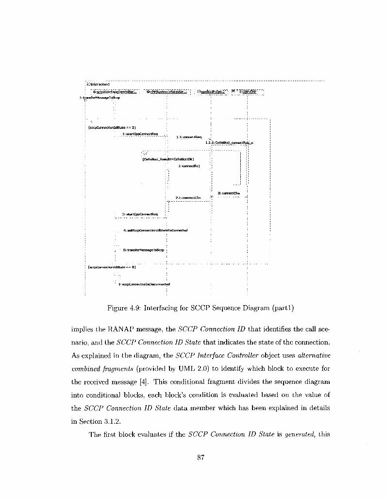
i Blhteracttonl
& sccplhterfaceCohtrolter,.,
1: transferMessageToSccp
f^cPPSyslien^VBoLBrtdar... l g | ^ ^ W™%tiiffiffl
[sccpConnecttaiildState -— 2 ]
1: startCppCormectReq l . l i comec tReq
1.1.1: CelloSccl_connettReiue
[CetloScci_ResuItl=Cel1oScciOK]
1: cormectRej
2.1:comectCfm
3: startCppConnectReq
4; ^tSccpConnectionldStateToCcnnected
5: transf erMessageToSctp :
[sccpConnecttonldState = = 0 ]
1: socpConnectionlsDisconnected
Figure 4.9: Interfacing for SCCP Sequence Diagram (parti)
implies the RANAP message, the SCCP Connection ID that identifies the call sce
nario, and the SCCP Connection ID State that indicates the state of the connection.
As explained in the diagram, the SCCP Interface Controller object uses alternative
combined fragments (provided by UML 2.0) to identify which block to execute for
the received message [4]. This conditional fragment divides the sequence diagram
into conditional blocks, each block's condition is evaluated based on the value of
the SCCP Connection ID State data member which has been explained in details
in Section 3.1.2.
The first block evaluates if the SCCP Connection ID State is generated, this
87

state indicates that the received message is the first message for a corresponding
call scenario and the SCCP connection is not establish yet with the CPP. So, the
SCCP Interface Controller object asks the CPP System to establish a connection
through the start CPP Connect Req operation, by receiving this request; the CPP
System invokes the connect Request operation from the CpxScciP object. By invok
ing the CelloSccLconnectReq.e, the CpxScciP object requests the CPP to establish
a connection through the SCCI interface for the corresponding call scenario [5]. If
the SCCP connection is established, the confirmation message will be received to
indicate a successful case. Once the SCCP connection is established, the SCCP
Interface Controller object changes the SCCP Connection ID State to " connected"
and invokes the transfer Message To SCCP operation. The second block checks
whether the SCCP Connection ID State is " disconnected", if this is the case, the
SCCP Connection Is Disconnected operation will be invoked to indicate the situa
tion.
The third block will be taken whether the SCCP connection is established and
the SCCP Connection ID State is " connected". If this is the case, then the received
message will be transferred through the start CPP data Request operation to the
CPP System. Once the CPP System receives this message, it asks the CpxScciP
object to transfer the data to the CPP platform through the CelloSccLdataReq-e
operation. The transferred data is the SCCP message that contains the RANAP
message portion and most likely the mobility management or the call control message
portion [15]. Once the CPP receives the message, it forwards it to the MSC where
the processing of the message and the message response will be performed. Once
the MSC process the message, it transfers its response message to the CPP platform
which forwards the message to the CPP System through the CpxScciP object. By
having this sequence, we achieve the connectivity functionality to the CPP and
consequently to the MSC server.
88

i ^ I n t e r a c t i o n !
' "l> sccpinterfaceCOfttroDerv.. ; H& cFPSysteni;*tBotJndar,, •. '- - gaScciP;Ctjx :.. ^ % C f f i f f i ?
[sccpConnectlonldSlate'== 1]
1: startCppDataReq
l . l :datoReq
1.1.1: CelloSccl_dataReq_e
2:dalalnd
2.1:datalnd
j j 2 .1 .1: transferCPPMessage
; [sccpConnectlonidState = = 3 ]
1; startSccpOisconnectionProcedure
Figure 4.10: Interfacing for SCCP Sequence Diagram (part2)
The forth block checks whether the SCCP connection state is " to be discon
nected" , if this is the case, the SCCP connection disconnection sequence diagram
shall be started for the corresponding call scenario. The " to be disconnected" state
is originally set by the call disconnection sequence diagrams in the Traffic Handler
component.
The Detach SCCPApfi Service is another sequence diagram provided by the
Detach SCCPApfi Service Use Case, it illustrates a sequence of messages to detach
the SccpApfi interface. No more SCCP services will be provided after detaching this
interface. The Disconnect SCCP connection is another sequence diagram that works
to disconnect the SCCP connection for a corresponding call scenario at the SCCI
interface. No more SCCP services will be provided for that call scenario after that.
More detailed information about these events' operations and sequence diagrams
can be found in Appendices A.l, A.2, and A.4.
89

4.2.3 UML Class Diagram
This section describes the class diagram for the interfacing functionality with the
CPP platform through the SCCP protocol. Figure 4.11 shows the UML representa
tion for this class diagram.
«Controf». S SCCPintfirfaceContrafcr
t^Cel^BjCdiiedflddWss j g^CeSoSca.CalnoAddress f &§CetoSca_.C3fedAddresslength * ££Celc6cQj:ainQAdctres5Length \ £§CeloSco_Conne(iionld > iiig CeloScaJJserDataLEnath SgCdbScdJJserData |::^CetoScd_ApSecvBrtd > j^attathSccpService ( ) \ ^setSccoSeWtsattachedToTrue ( ) ; ^setscqjSwweisattathedToFdse ( ) . I ^setScqaComecflonldStateToCormected ( ) ; ^transferMessaQeToSccp (•> s ^setSccpCOTnecttonkStateToOsccmected ( ) i ^startSccpDiscannBctiorProcedur© [ ) t ^detachSccpServtce ( ) : C^tjansferCPPMessage ( ) > ^Adgr^.sccpCoiviecttoraEDfeconnectedC)
Requires opera tions
' «*rterface» W\lCPPSystem
{&; start* ttathReq [ ) ^startCppConnettReq ( ) (g,startCp[dsconiie£tR9q ( ) fi^staFtDetachfteq ( ) 63>startCppOataReo ( )
i (& transferMessaoeToScep ( )
*Boundaiv l#CPPSystem
i-£3ttachRef CgtBentlD
^star tAt tadTReqO' 1 \ -^attachToServiceCfTT! ( )
•^startCppCnmectRea ( ) c p p i ^ c o n n e c t C f m ( )
: %startCppDalaReq ( ) ! ^ d a t a l n d C) = ^statCrafisconrectReq ( )
l ^ d b c i h d O -: ^StartDetachReq ( ) I ^detachFuxnSerwceCfm ( )
^ <dnterfacs» .. M= ICfixSapAph
^attachtoServiireReq't") \ ^detachFrornServtceReq ( ) \
1 j CpxStcpApflAttathP "••
Eatt3thRef • . jdsnt lD \
^attachTOServte'eRsei'O' " ^attachToServfceCfm ( ) ^.detachfromServtceReq ( ) :
. ^detacWromSeiviceCtrn ( ) ;
«Jr>taface» T-tCPPwahQac
^cormectRej ("J ^cormectChn [ ) ^ d a t a l n d . O ^attactiToSaviceCfm ( ) ^d te t lnd ( ) j^detachFtGmSetviceCftn ( )
«riterfaee» '$i JCpxSai
g^eormectReq ( ) £*,dataReq() g&dscRgq ( )
Irrcternents
i J S e » • •
^comec tReq ( ' ) i $jj, connect Cfm ( ) 1 G§,datafieq (>
= l&d*tamd ( ) ^d j scReoO ^.c fec lndO
Figure 4.11: Interfacing for SCCP Class Diagram
The class diagram shows all classes that participate to communicate and in
teract with the CPP platform. It shows the SCCP Interface Controller, the CPP
System, and the CPP library classes and how they cooperate through UML rela
tionships. The SCCP Interface Controller class is associated with the CPP System
class through the ICPPSystem interface, where the SCCP Interface Controller has
an association relationship with (1 - 0..*) multiplicity [4]. This notation means that
one object of the CPP System is associated with one or many objects of the SCCP
90

Interface Controller.
The SCCP Interface Controller class uses services from the ICPPSystem in
terface which is implemented by the CPP System class. In the same way, the CPP
System uses the ISCCPwithCPP interface which is implemented by the SCCP Inter
face Controller. Furthermore, the CPP System class implements the ICPPwithCpx
interface to provide services for the CPP library classes which are the CpxSccpAp-
fiAttachP and the CpxScciP classes, in the same way, these classes implement the
ICpxSccpApfi and ICpxScci interfaces respectively to be used by CPP System class
in order to communicate with the CPP platform. More information about Interfaces
and classes can be found in Appendices A.l, A.3, and A.4.
4.3 Summary
In this chapter, we modeled the functional behavior of the RANAP Controller and
the SCCP Interface Controller components through the UML Analysis Model. We
provided the UML logical implementation for the RANAP Controller component
which behaves as the main coordinator for all interactions that occur in the Ranap-
Sim system. On the other hand, we modeled the SCCP Interface Controller com
ponent that handles the CPP platform interfacing through the SCCP protocol, as
a consequence of this, the RanapSim components will be able to communicate with
the MSC server.
In the UML Analysis Model for those two components, we identified the analy
sis classes and built the Use Cases' realizations that illustrate all possible interactions
that reflect the functional behavior of each Use Case. In addition, we presented all
class diagrams that show the structure of the provided model. The correctness of
the RANAP Controller and the SCCP Interface Controller components' models has
been checked through the formal check process at Ericsson [50].
91

Chapter 5
Conclusion and Future Work
5.1 Conclusion
In this thesis, we presented a model for a Traffic Generator to load the Mobile
Switching Center (MSC) by generating the control plane traffic (signalling) on the
Universal Mobile Telecommunications System (UMTS), the traffic generator model
can be used for the MSC load testing applications. We proposed high level analysis
and design for the Radio Access Network Application Part (RANAP), the Mobility
Management, the Call Control protocols for the Circuit-Switched network.
We have modeled the RanapSim Traffic Generator that provides the functional
behavior of the RANAP, the MM, and the CC protocols to generate traffic on the
IuCS interface between the RNC and the MSC. Most of the traffic generator models
-that are used for the same purpose- provide a solution by modeling the whole
UTRAN components' protocols to generate traffic towards the MSC. Based on this
fact and based on our technique of modeling, we can say that the RanapSim model
is an efficient solution to generate traffic towards the MSC server.
We provided a UML Use Case Model which describes the RanapSim functional
requirements in terms of Use Cases; the Use Case Model illustrates the main specifi
cations and the functional behavior of the proposed traffic generator. Furthermore,
92
we provided a UML Analysis Model which describes the structure of the RanapSim
system, in this model, we identified the analysis classes, illustrated the sequence
diagrams, and built the class diagrams that provide the RanapSim's logical imple
mentation of the functional requirements that we identified in the Use Case Model.
The RanapSim traffic generator models have been checked through a process called
formal check, this process is used to evaluate the correctness for technical contents
for any design at Ericsson.
In terms of functionalities, the RanapSim provides models for many call sce
narios that represents the mobile station. These call scenarios are; Location Update,
Mobile Originating Call, Mobile Terminating Call, and Call Disconnect. Through
these call scenarios, the signaling traffic can be generated to load the MSC in order
to measure the performance of the MSC; this traffic generator is not intended for
verifying the actual MSC design functionality.
Furthermore, we modeled the RANAP protocol's procedures that have been
used to handle the call scenarios messages and to generate the RANAP messages.
Also, those procedures' models have been used to represent the radio access network
signalling part of the RNC server. The RANAP procedures that have been modeled
are; Paging functionality, Radio Access Bearer (RAB) Management, UE-CN direct
transfer, Security Mode Control, Initial UE Message, Iu Release, as well as Common
ID.
Finally, the RanapSim Traffic Generator has been modeled based on the CPP
platform specification through the SCCP protocol. This platform provides two func
tionalities; the protocol transport functionality which has been utilized in this model
to communicate with the MSC, and the execution functionality which can be utilized
to execute the real implementation of this model.
93

5.2 Future Work
As a future work, the real implementation for the RanapSim Traffic generator mod
els can be done by making use of the UML Use Case and Analysis Models that have
been provided in this thesis. The models implementation shall present the Ranap
Sim Tool that can be used for the MSC load testing. In the real implementation,
traffic consists of many test cases that can be generated out of location update,
mobile originating, or mobile terminating call scenarios models; by generating test
cases, we can make sure that the MSC will be properly loaded. Besides, the Ranap
Sim Tool should have the RanapSim Manager, Server, GUI, and CLI components
implemented.
Furthermore, this traffic generator can be modeled using the executable UML,
the resulting model using this language is composed by a set of modeling elements
which are; domain chart, class diagram, action language, and statechart diagram [4].
In addition, as a future work, more mobile call scenarios can be modeled using
the call control and the mobility management protocols' models; the Call Forwarding
and Call Waiting are examples of other mobile call scenarios that can be modeled
and integrated easily within the RanapSim system.
The traffic generation models that are proposed in this thesis handle the traffic
of a Radio Network Controller (RNC) that is communicating with one MSC server.
As a future work, the traffic distribution in a multi-processor application can be
modeled to generate traffic similar to multiple RNCs traffic to have extremely high
traffic load generation.
Finally, as a future work, it is possible to reuse some of the modeled compo
nents to model a traffic generator to load the Service GPRS Support Node (SGSN).
Generating SGSN call scenarios will require models for the GPRS Mobility Man
agement protocol and the GPRS Session Management protocol; these protocols will
be carried through the RANAP protocol and the call connections can be handled
through the SCCP protocols. Based on that, many components from the RanapSim
94

model can be reused for this purpose such as; the SCCP Interface Controller and
the RANAP Controller.
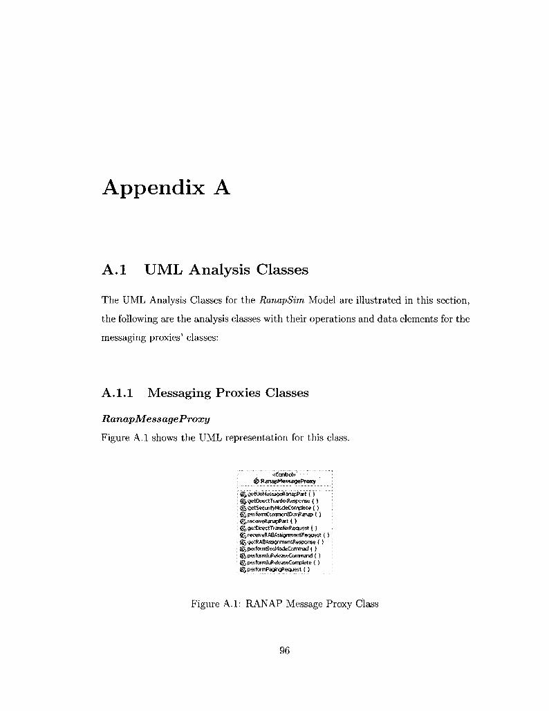
Appendix A
A . l UML Analysis Classes
The UML Analysis Classes for the RanapSim Model are illustrated in this section,
the following are the analysis classes with their operations and data elements for the
messaging proxies' classes:
A. 1.1 Messaging Proxies Classes
RanapMessageProxy
Figure A.l shows the UML representation for this class.
# RanapMessageProxy
|5§,getDitectTianfefRespome <)
i | psffcrmCofrroonlDanRanap C S SfJreostveRarBpPart ( ) ^getDirectTiarefe<ftequ«t C )
J^getRABAsSgrinwmgspcree ( ) gJ,psffe»mSecf4«teConiniad4 )
%peformluR«feasi»Camptete { ) S | pafermPagri0<eqLiest C )
Figure A.l: RANAP Message Proxy Class
96

operations for RanapMessageProxy:
RanapMessageProxy::getUeMessageRanapPart
Operation Parameters: requestType; specifies which call scenario is required.
The requestType could be location update request, CM service request, or paging
response.
Possible return messages: InitialUeMessage
The purpose of the Initial UE Message procedure is to establish an Iu sig
naling connection between the MSC domain and the RNC -for specific UE- and to
transfer the initial NAS-PDU message to the MSC. The InitialUEMessageController
object will call this operation to get an Initial UE message for certain call scenario
specified in the requestType. Based on the requestType, this operation will invoke
an appropriate operation in the MM proxy to get the proper NAS-PDU message.
Upon receiving the NAS-PDU message (MM), this operation will initiate the Ini
tialUeMessage (RANAP) by adding other data fields such as; LAI, SAI, and Iu
signaling connection Identifier.
RanapMessageProxy: :getDirectTranfer Response
Operation Parameters: UserData; points to the RANAP actual message.
Possible return messages: DirectTranferMessage
The DirectTransferController object will call this operation to get the response of
the direct transfer request which will usually carry the NAS-PDU message (e.g.,
CC or MM). The purpose of the Direct Transfer procedure is to carry UE-MSC
signalling messages over the Iu Interface. The UE-MSC signalling messages are not
interpreted by the RNC. The UE-MSC signalling messages are transported as a pa
rameter in the Direct Transfer messages. The UE side is represented by the MM
97

message proxy or the CC message proxy.
RanapMessageProxy::getDirectTransferRequest
Operation Parameters: None
Possible return messages: DirectTransferMessage
The DirectTransferController object will call this operation to create direct trans
fer message request that will carry a CC message to start a call control procedure
such as; call setup, call connect, or call alerting. typeOfCcService parameter will be
passed -through this operation- to the getCcPart operation.
RanapMessageProxy::performSecModeCommad
Operation Parameters: UserData; points to the RANAP actual message.
Possible return messages: SecurityModeCompleteMessage
The SecurityMode Controller object will call this operation. This operation
carries the Security Mode Command to the RANAP Message Proxy to decode the
message and generate the appropriate response. For more information, see the get-
Security Mode Complete operation described next.
RanapMessageProxy::getSecurityModeComplete
Operation Parameters: UserData; points to the RANAP actual message.
Possible return messages: SecurityModeCompleteMessage
This operation will be called by the class's object itself to perform the security mode
complete procedure which is a RANAP procedure. This operation responds to the
SecurityModeCommandMessage by extracting the Encryption Information IE and
the Integrity Protection Information IE, then choosing appropriate ciphering and
98

integrity alternative algorithms. When the integrity and the ciphering configuration
are successfully chosen for the radio interface procedure, the object of this class shall
return a SECURITY MODE COMPLETE message to the caller in order to send it
to the MSC.
RanapMessageProxy::performCommonIDonRanap
Operation Parameters: UserData; points to the RANAP actual message.
Possible return messages: None
The CommonID Controller object will call this operation to forward the Com
mon ID message to the RANAP Proxy object, and to perform the Common ID
procedure there. In real life, the purpose of the Common ID procedure is to inform
the RNC about the permanent NAS UE Identity (i.e., IMSI) of a user. This is used
by the RNC to create a reference between the permanent NAS UE identity of the
user and the RRC connection of that user for RNC paging procedure. This opera
tion will save the received "IMSI" in the CommonlDMessage object, in order to use
it for other operations for that UE or user. We call this operation of attaching the
"IMSI" to the UE, Location Update - IMSI attach.
RanapMessageProxy::receiveRanapPart
Operation Parameters: UserData; points to the RANAP actual message.
Possible return messages: None
The DirectTransferController object will call this operation to forward the received
RANAP message to the RANAP proxy only, without expecting any return message.
RanapMessageProxy::receiveRABAssignmentRequest
99

Operation Parameters: UserData; points to the RANAP actual message.
Possible return messages: RABAssignmentRespMessage
The RABAssignmentController object will call this operation to handle this request.
This operation will check the messageType to recognize the message. Based on the
message type it call an appropriate operation to perform the RAB Assignment pro
cedure and generate the response. Also, this request contains the list of RABs to
be established or modified. In this case the getRABAssignmentResponse operation
will be called.
RanapMessageProxy::getRABAssignmentResponse
Operation Parameters: UserData; points to the RANAP actual message.
Possible return messages: RABAssignmentRespMessage
The receiveRABAssignmentRequest operation will call this operation, which will
forward the RAB list to be established or modified. This operation will generate
the RABAssignmentRespMessage -which will confirm the RAB request that comes
from the MSC- and send the established/modified RAB ID to the MSC. This oper
ation will simulate that the RABs are established by the RNC for a given UE; this
operation will be understood by the MSC.
RanapMessageProxy::performPagingRequest
Operation Parameters: UserData; points to the RANAP actual message.
Possible return messages: TRUE when the paging request received successfully,
or FALSE if not.
The purpose of the Paging procedure is to enable the MSC to request the RNC to
contact that UE. Normally, the MSC will initiate the procedure by sending pag-
ingRequestMessage. The paging message shall contain various IEs such as; IMSI,
100

TMSI, paging area, and others. Based on the message received, the RNC will send
broadcast or uni-cast message to find the needed UE. This operation will receive
the paging request, save some of the IEs that could be needed in the paging re
sponse message, and return "True" to the operation initiator to initiate the Paging
response message. In this case, the initiator will be the CallTerminatingController
object. The Paging request is a RANAP message, but the Paging response is an
MM message.
RanapMessageProxy::performIuReleaseCommand
Operation Parameters: UserData; points to the RANAP actual message.
Possible return messages: IuReleaseCompleteMessage
For more details, see next operation.
RanapMessageProxy::performIuReleaseComplete
Operation Parameters: UserData; points to the RANAP actual message.
Possible return messages: IuReleaseCompleteMessage
The purpose of the Iu Release procedure is to enable the MSC to release an Iu con
nection and all RNC resources related only to that Iu connection. The Iu Release
procedure will be initiated when the transaction between the UE and the MSC get
completed. Also, the Iu Release procedure is initiated for other reasons, not impor
tant for our system. The luRelease Controller object will invoke the performluRe-
leaseCommand operation. This operation will carry the IuReleaseCommandMessage
to the RANAP Message Proxy to release the Iu signaling connection for the corre
sponding UE. While invoking this operation, the performluReleaseComplete will be
invoked to perform the release and generate an appropriate response to send back to
101

the initiator. The performluReleaseCommand will get the IuReleaseCompleteMes-
sage and send it to its initiator in order to send that to the MSC.
ft pagingRequestMessage i j messagifype i j cnDomaWodscator g | permar»«t»NAS-W£-fctentity S|j tempotarvUEWenWy' E||p3glngAreaE> Ej|pagingeatBe
^ E n t i t y A InitiatUeMessage
; SJNAWOU I • B'| CrMDemairftidfeatef j : S i LAI ! KlSAI ! g^It^gnain^OT»»ctkrtdentJS«r j B|gtobaIRNC-!D I Ej|GER»fClas$m»rt; _ j
••/ ."*eytnr»: •'; # RABAss'gnmentftespMessage
is^m^agetype BijiabsSetupOtModifted iSyAsRsleased BQ, rabtfatedToSeti^Ot Modified
' " ' • • ' " ' • . " ' « & « & » " • " • : " ' • ' • ' - • ' • •
& Se<iirityModeCommamWc553ge ^messagafype
eg erwryptteUnfoinattw £si«t'6yStatus
\ ft SeairityMmieCompieteMessage
i'q|rn<Xagefvp« "' I s^chosenlnte^ityfto&sctwi Algorithm ; Kf,cho«»nBKKpttanAlgsithm i s^aittcattvDiagriosUcs
' ft SecurityModeCompleteMessage -• BSjirressageType
KgChisserilnteorit'sPiotectton algorithm iif| chosengrra ypttanAlgorrthm ££ a iticalityDiagnostKs
v" - «EnHty» ! ft CcHRHtoniOMessaoe
fr|msssig«fyp<f " ' ] islc«rrTwant-H*S-U6-Identitv j
* & * » » ' : ; • ' • • ' • ' • • ' " " • '
: # DirectTranfefMesssge
'. |:|mes3gefvpe ' sgNAS-PDU iiSSAPl
ft IUReleaseComroarKMe«age
: ggeauw
•fEmity**:' fi RABAsstgnmentReqMessage
^message type &% userPtenelnformatten B | rabsTee»»SetupQiM<sdifed B» labToBeReteased
r •'•'"-:: : *Bitity;» ft IuRcIeascComuIeteMessage
: SJ mSssagefypa ! KJRAKdOfRABsDataVdimwSepwtUst : | K&RABIdOfRABsRefeasedltTOlEs
Figure A.2: Ranap Message Proxy's Entity Classes
Figure A.2 shows the Entity classes located in the RanapMessageProxy class.
102

MobilityManagmentMessageProxy
This class works as an agent or proxy for receiving, decoding, preparing, and for
warding various Mobility Management (MM) messages. Figure A.3 shows the UML
representation for this class.
Class Data Members: T3230; this is a timer which is started by the Mobility Man
agement Message Proxy when the CmServiceReqMessage is sent, and stopped when
the CmServiceAcceptMessage or the CmServiceRejMessage is received.
i i ^ MobilityManagmentMessageProxy
i£g'T3230 f^geSocMpdKeqMmPart ( j ^gstMmResponse {) %authenticationReaction ( } |j,locattonUpdateAccept!) fttocatiom*dateComptete ( ) (^getQnServiceReqMmPart ( ) j|reeetveMmPaft ( )
H $ t a r t T l m e r { ) ^stopTimer ( ) S|getPagingResponseMmPa't ( ) ^rete«s«MMconnsction ( ) ^taeatfonUpdateRej ( ) ^tocattonUpdateFaiure ( ) lllpeifoimCmSerwceAccepted (5 ^perforniCrnServiceRejected { ) U&receiyeAuthenticationRequest ( )
Figure A.3: Mobility Management Message Proxy Class
operations:
MobilityManagmentMessageProxy-getLocUpdReqMmPart
Operation Parameters: NAS-PDU; points to the Call Control or the Mobility
Management actual message.
103

Possible return messages: LocationUpdateReqMessage
The RanapMessageProxy object will call this operation. The normal location up
dating procedure is used to update the registration of the actual Location Area of
a mobile station in the network. The location updating type information element
in the LocationUpdateReqMessage shall indicate the IMSI attach. This operation
will be responsible for assigning values to the IEs in the LocationUpdateReqMes
sage such as; the locationUpdatingRequestMessageType, LAI, protocolDiscrimina-
tor, and others. The return message from this operation will be sent through the
Initial UE Message to the MSC to start the location update procedure.
Mobility ManagmentMessageProxy::getMmResponse
Operation Parameters: NAS-PDU; points to the Call Control or the Mobility
Management actual message.
Possible return messages: Mobility Management message response
The RanapMessageProxy object will call this operation. This operation will carry
the MM message (request), invoke an appropriate operation to get response, and
return the response back to the initiator. In this case, the getMmResponse will
carry the authenticationReqMessage -coming from the MSC- and will return back
either the authenticationResMessage or the authenticationRejMessage.
MobilityManagmentMessageProxy::authenticationReaction
Operation Parameters: NAS-PDU; points to the Call Control or the Mobility
Management actual message.
Possible return messages: authenticationResMessage or authenticationRej Mes
sage.
The MM message proxy object will recognize the authenticationReqMessage by
104

checking the messageType, after that it will invoke the authenticationReaction to
accept or reject the authentication procedure. The purpose of the authenticationRe
action operation is to permit the network to check whether the identity provided by
the mobile station is acceptable or not. Also, this will allow the network to provide
parameters enabling the mobile station to calculate a new UMTS ciphering and in
tegrity keys. Furthermore, this operation permits the mobile station to authenticate
the network.
After calculating the ciphering integrity keys properly, the authenticationReaction
will return back the authenticationResMessage to indicate the acceptance or the
authenticationRejMessage to indicate the rejection. Since we are concentrating on
traffic generation, we will indicate acceptance all the time unless the case requires
rejection.
MobilityManagmentMessageProxy::receiveLocationUpdateAccept
Operation Parameters: NAS-PDU; points to the Call Control or the Mobility
Management actual message.
Possible return messages: None
For more details, see next operation.
Mobility ManagmentMessageProxy::receiveLocationUpdateRej
Operation Parameters: NAS-PDU; points to the Call Control or the Mobility
Management actual message.
Possible return messages: None
The RanapMessageProxy will forward the MM message to the MobilityManag-
mentMessageProxy object. This object will check the value of the messageType
as follows:
105

If the messageType = "xxOO OOIO"
This means that the MM message is LocationUpdateAcceptMessage. So, the re-
ceiveLocationUpdateAccept operation will be invoked to indicate that the IMSI is
activated in the network and to store the received location area identification (LAI).
If the messageType = "xxOO 0100"
This means that the MM message is LocationUpdateRejMessage. So, the receiveLo-
cationUpdateRej operation will be invoked to indicate that the IMSI is not activated
in the network and to store the received rejectCause.
Mobility ManagmentMessageProxy::getCmServiceReqMmPart
Operation Parameters: None
Possible return messages: CmServiceReqMessage
The RanapMessageProxy object will call this operation. This operation will gener
ate the CmServiceReqMessage and return it back to the initiator. This message will
be carried by the Initial UE Message (RANAP Message) in order to establish MM
connection in the MSC side. The CmServiceReqMessage is the first message in the
call originating scenario. While the execution of this operation, the timers T3230
(MM timer) and T303 (CC timer) shall be started.
MobilityManagmentMessageProxy::performCmServiceAccepted
Operation Parameters: NAS-PDU; points to the Call Control or the Mobility
Management actual message.
Possible return messages: None
For more details, see next operation.
Mobility ManagmentMessageProxy::performCmServiceRejected
106

Operation Parameters: NAS-PDU; points to the Call Control or the Mobility
Management actual message.
Possible return messages: None
The RanapMessageProxy will forward the MM message to the MobilityManag-
mentMessageProxy object. This object will check the value of the messageType
as follows:
If the messageType = "xxlO 0001"
This means that the MM message is CmServiceAcceptMessage. So, the performCm-
ServiceAccepted operation will be invoked to indicate that the CM service request
is accepted and the MM connection has been established. Timer T3230 shall be
stopped.
If the messageType = "xxlO 0010"
This means that the MM message is CmServiceRejMessage. So, the performCmSer-
viceRejected operation will be invoked to indicate that the CM service request can
not be accepted. Timer T3230 shall be stopped.
Mobility ManagmentMessageProxy::receiveMmPart
Operation Parameters: NAS-PDU; points to the Call Control or the Mobility
Management actual message.
Possible return messages: None
The RanapMessageProxy object will call this operation. This operation will carry
the MM message, and invoke an appropriate operation to receive the MM message
without returning any response back to the initiator. The receiveMmPart will carry
various messages such as; CmServiceAcceptMessage, CmServiceRejMessage, Loca-
tionUpdateAcceptMessage, or LocationUpdateRejMessage.
107

Mobility ManagmentMessageProxy::getPagingResponseMmPart
Operation Parameters: UserData; points to the RANAP actual message.
Possible return messages: PagingResponseMessage
At reception of a pagingRequestMessage (RANAP message) from the MSC, the
RanapMessageProxy will invoke this operation from the MM message proxy. The
getPagingResponseMmPart will create a PagingResponseMessage (MM message) as
a response to the paging request message. The PagingResponseMessage shall be
sent to the MSC to indicate that the required UE is located, the paging procedure
is completed, and the MSC can start contact that UE. In our model, this UE rep
resent the MS call terminating entity. The PagingResponseMessage will be the first
message sent from the MS call terminating entity.
Mobility ManagmentMessageProxy::releaseMMconnection
Operation Parameters: None
Possible return messages: None
When the CC proxy receives a ReleaseMessage, it will also ask the MM proxy
-through releaseMMconnection operation- to release the Mobility management re
sources to complete the release procedure at the UE side.
Mobility ManagmentMessageProxy::startTimer
Operation Parameters: timerld; indicates the timer identity
Possible return messages: Boolean
This operation shall be invoked when the MM message proxy requires to start a
timer which belongs to the Mobility Management procedures.
108

Mobility ManagmentMessageProxy::stopTimer
Operation Parameters: timerld; indicates the timer identity
Possible return messages: Boolean
This operation shall be invoked when the MM message proxy requires to stop a
timer which belongs to the Mobility Management procedures.
109

S pagingRequestMessage s ; |mes is^ ty (» Kg cnOomaWhd&cator m petmmaWNAS-liE-Jdaitity BH tamper avieidsntit^ ggpngingArealD egpagingCause B|giot«KN-lD
«<Enttty» ft InitiaWeMessage
i ejmesssgaTvpe ; i |NAS4'0U
: g § U l
gj|iuSignalngeerm«ttaidd^tjftef : E|gtob<StrC-lD ; BSjGERANCtassmarl:
<€Mlty* @ RABAssignmentRespMessage
I KjmessagsType I Ka'dssSetupOiModited ! 8Jr«ibsReteaswS I g^rabsFatedToSetupOtModifted : gj rabsFaJedToReleased
' "«6 l»ty . @ SecurityModeConimandMessage
sj|)ntegritvRotectioriInfo!iTOtt3r> S J enct ypticrtlrtfotmata) tl.teystat.us
;'•'! :?: «Enttty» : S SKurityModeCompieteMessage ' t § messagstype j e^crK»enIntesrtU-Piot<Ktm Algwlthm i i'^chosenBxiwtiOTAlasithm i OiCTittcalttyD&grtosaes
: «6n»V» ! ft SecurityModeCompleteMessage '. Bjmessagetvps • KjCrx>«nIr>tegtitV'PiotettK>ri Algorithm
1 ^ chosenEna "/ptionAlgorithm BjjciiticattyDiagnostics
«B)Bty» ft CommonlDHessage
I simessagefyp* ; ejpe(rrBriei'it-NAS4je-IdenW;^ ,
• oEnttt?» ' # Direct TranfetMessage : ig^messageT^pe ; igNAS-POU SSAPI
I " «Enttty» ft luReteaseComnMndMessage
, B|,rnsssaaeT>pe K|C3U59
I 8 RABAssjgnmentReqMessage
EjlmBssagefype I | i userPbnelnfotroaBon 1 | rabsToBsSetupQiMccSrfed i t i , rabToBetteleased
ft iuReiea$eCor»pi«teMe»age S|me»agetype &§RABIdCKRJ>BsOaUVcium*«portU« i SRABIdOfRABsRetessedRemlB
Figure A.4: Mobility Managment Message Proxy's Entity Classes
Figure A.4 shows the Entity classes located in the MobilityManagmentMessageProxy
class.
110
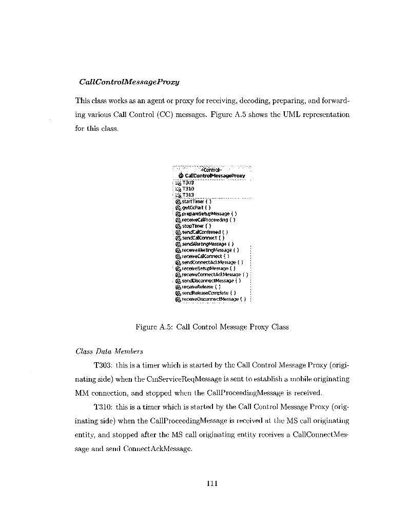
Cal I ControlMess ageProxy
This class works as an agent or proxy for receiving, decoding, preparing, and forward
ing various Call Control (CC) messages. Figure A.5 shows the UML representation
for this class.
I # CallControlMessageProxy ri |T303 ISj|"f310 ! §|T313 ___ : ^s tar t i f iW ( } j ftgetCcPat {5 ; ® pr*par*SetMpMes$age ( } ; i|receke€38Pr<xe«fr>g { ) ; ^stopTkmr (') ; ^sendCalCcrtimed ( ) : ^sendCaKorsnect { j
• ^s«ncfCormectittl*le$«ge { ) : fj^recefveSefupMesas* { ) i ^receweComectAdMesMge { ) i fjflsandDisconnectMessage { ) : H|r«:eiveRete5e { ) SgjsendReteasetompfete ( )
\ fereceiveDtscomecWessage { )
Figure A.5: Call Control Message Proxy Class
Class Data Members
T303: this is a timer which is started by the Call Control Message Proxy (origi
nating side) when the CmServiceReqMessage is sent to establish a mobile originating
MM connection, and stopped when the CallProceedingMessage is received.
T310: this is a timer which is started by the Call Control Message Proxy (orig
inating side) when the CallProceedingMessage is received at the MS call originating
entity, and stopped after the MS call originating entity receives a CallConnectMes-
sage and send ConnectAckMessage.
I l l

T313: this is a timer which is started by the Call Control Message Proxy (ter
minating side) when the CallConnectMessage is sent from the MS call terminating
entity, and stopped after the MS call terminating entity receives a ConnectAckMes-
sage.
operations for CallControlMessageProxy:
CallControlMessageProxy::getCcPart
Operation Parameters: NAS-PDU; points to the Call Control or the Mobility
Management actual message. typeOfCcService; indicates type of service that the
CC proxy should provide.
Possible return messages: Call Control message response
The RanapMessageProxy object will call this operation. This operation carries -as
a parameter- the CC message or/and typeOfCcService, to indicate the CC proxy
which operation need to be performed, and return the response back to the initiator
-if applicable-. Based on the parameters of this operation (CC message and type
OfCcService), and based on which entity this operation shall be performed (originat
ing or terminating entity), the CC message proxy will perform the proper operation.
CallControlMessageProxy::prepareSetupMessage
Operation Parameters: None
Possible return messages: SetupMessage
The CallControlMessageProxy object (at the MS call originating entity) will call
this operation. This operation will prepare the SetupMessage which shall contain
all the information required by the MSC to process the call. In particular, the
SetupMessage shall contain the calling and the called party addresses information.
112

Also, the SetupMessage initiates a mobile originating call establishment.
CallControlMessageProxy::receiveSetupMessage
Operation Parameters: NAS-PDU; points to the Call Control or the Mobility
Management actual message.
Possible return messages: None
Upon completion of the MM connection (for the terminating side), the call control
entity of the MSC shall send a SetupMessage to its peer entity (CC) at the MS call
terminating entity. The CallControlMessageProxy object (at the MS call terminat
ing entity) calls this operation. This operation will receive the SetupMessage and
will indicate the successful compatibility checking. This message is sent by the MSC
to the MS call terminating entity to initiate a mobile terminated call establishment.
CallControlMessageProxy: :sendCallConfirmed
Operation Parameters: None
Possible return messages: CallConfirmedMessage
As an acknowledgment of successfully receiving the SetupMessage, the CallCon
trolMessageProxy (at the MS call terminating entity) prepares and sends the Call
ConfirmedMessage by invoking this operation. All this happens to indicate that the
incoming call request for the MSC has been confirmed.
CallControlMessageProxy: :receiveCallProceeding
Operation Parameters: NAS-PDU: points to the Call Control or the Mobility
Management actual message.
Possible return messages: None
113

Once the MSC receives a CallConfirmedMessage from the MS terminating entity,
the call control entity of the MSC will send a CallProceedingMessage to the MS
originating entity. The CallControlMessageProxy object (at the MS call originat
ing entity) calls this operation. Through this operation, the CallProceedingMessage
shall be received to indicate that the requested call establishment information has
been received at the terminating side.
CallControlMessageProxy: :send AlertingMassage
Operation Parameters: None
Possible return messages: AlertingMessage
Upon completion of the RAB Assignment Procedure at the MS terminating entity,
the CallControlMessageProxy object -in this entity- will prepare and send the Alert
ingMessage by invoking this operation. This message will be sent to the call control
entity at the MSC to indicate that the alerting procedure has been initiated at the
MS terminating entity.
CallControlMessageProxy::receiveAlertingMessage
Operation Parameters: NAS-PDU; points to the Call Control or the Mobility
Management actual message.
Possible return messages: None
Once the MSC receives an AlertingMessage from the MS terminating entity, the
call control entity of the MSC will send a corresponding AlertingMessage to the MS
originating entity. The CallControlMessageProxy object (at the MS call originating
entity) invokes this operation. Through this operation, the AlertingMessage shall
be received to indicate that the alerting procedure has been initiated at the MS call
terminating entity.
114

CallControlMessageProxy::sendCallConnect
Operation Parameters: None
Possible return messages: CallConnectMessage
The CallControlMessageProxy object -at the MS call terminating entity- prepares
and sends the CallConnectMessage by invoking this operation. This message will be
sent to the call control entity at the MSC to indicate that the call has been accepted
at the called entity.
CallControlMessageProxy::receiveCallConnect
Operation Parameters: NAS-PDU; points to the Call Control or the Mobility
Management actual message.
Possible return messages: None
Once the MSC receives a CallConnectMessage from the MS terminating entity, the
call control entity of the MSC will send a corresponding CallConnectMessage to
the MS originating entity. The CallControlMessageProxy object (at the MS call
originating entity) invokes this operation. This operation receives the CallCon
nectMessage which indicates.
CallControlMessageProxy::sendConnectAckMessage
Operation Parameters: None
Possible return messages: ConnectAckMessage
The CallControlMessageProxy object -at the MS call originating entity- shall, upon
receiving a CallConnectMessage, attach the user connection. Also it will prepare
and send the ConnectAckMessage by invoking this operation. This message shall
115
be sent to the call control entity at the MSC to acknowledge the offered connection.
CallControlMessageProxy::receiveConnectAckMessage
Operation Parameters: NAS-PDU; points to the Call Control or the Mobility
Management actual message.
Possible return messages: None
Once the MSC receives a ConnectAckMessage from the MS originating entity, the
call control entity of the MSC will send a corresponding ConnectAckMessage to
the MS terminating entity. The CallControlMessageProxy object (at the MS call
terminating entity) invokes this operation. This operation receives the Connec
tAckMessage which indicates that the MS terminating entity has been awarded the
call.
CallControlMessageProxy::sendDisconnectMessage
Operation Parameters: None
Possible return messages: DisconnectMessage
Upon receiving a Call Disconnect command from the system Manager, the CallCon
trolMessageProxy object -at the originating or terminating entity- shall stop all the
running timers in the corresponding entity and send DisconnectMessage to request
the MSC to clear an end-to-end call connection by invoking this operation. The
DisconnectMessage contains a "cause" information element (IE) which indicates the
disconnection cause at the MSC side.
CallControlMessageProxy::receiveDisconnectMessage
Operation Parameters: NAS-PDU; points to the Call Control or the Mobility
116

Management actual message.
Possible return messages: None
Upon the MSC receive a DisconnectMessage from any entity in the end-to-end con
nection, it will send a corresponding DisconnectMessage to the other connected
entity. The CallControlMessageProxy object (at this connected entity) will call this
operation to receive the DisconnectMessage; this message indicates that the end-to-
end connection has been cleared. The cause of the disconnection can be found in
the "cause" IE.
CallControlMessageProxy ::receiveRelease
Operation Parameters: NAS-PDU; points to the Call Control or the Mobility
Management actual message.
Possible return messages: None
Once the MSC receives a DisconnectMessage from any entity in the end-to-end
connection, it will send a ReleaseMessage to the connected entities. The CallCon
trolMessageProxy object (at the originating and terminating entity) will call this
operation to receive the ReleaseMessage which indicates that the MSC intends to
release the transaction identifier and that the receiving entities shall release the
transaction identifier, and stop all running timers. The transaction identifier is used
for protocol error handling (see reference [4]).
CallControlMessageProxy ::sendReleaseComplete
Operation Parameters: None
Possible return messages: ReleaseCompleteMessage
Upon a receipt of a DisconnectMessage from the MSC, the CallControlMessage
Proxy object -at the originating or terminating entity- shall stop all running timers
117

-which corresponds to a specific call- and send a ReleaseCompleteMessage to indi
cate that the originating or terminating entity has released the transaction identifier
and that the MSC shall release the transaction identifier.
CallControlMessageProxy-startTimer
Operation Parameters: timerld; indicates the timer identity
Possible return messages: Boolean
This operation shall be invoked when the CC message proxy requires to start a timer
which belongs to the Call Control procedures.
CallControlMessageProxy::stopTimer
Operation Parameters: timerld; indicates the timer identity. If the operation
parameter is not provided, the operation will stop all running timers for the corre
sponding entity.
Possible return messages: Boolean
This operation shall be invoked when the CC message proxy requires stopping a
timer belongs to the Call Control procedures.
118

«Entitv» '""• ft CallConnectMessageContent j
Kg ptotocofDisoMrwtof i Qtransactionlctentiftef : IfJcomectMessaaeType i Eg tetty •; sjuset-usa i ^Uprogresslndotcs : isgcomettetWtmtses 1 Ejconneeted&iwttess
'••' >6nHtv»" ' ; v : w ; " - :
S CallConfirmwWessagcContcnt
u piotixsBciitniriator a transactioriiderrtifter D catConftme^HessageType
t a ispsatln*c4tat i ab«aierCap*$ty lQeause
sccCapabittes ^streanUdgntifief
~ suppot tedCodecs
; "BStty» ® SetupMessageContent
> mprotocoBfso*Hh*or j entfamacttonldeittSsr i ei^tupMsssageTyp* i iifstreamldenfite j B|beae»Cap*iiit» I e^cafedPartyBCONumbe ' KjsjpportedOxJecs ! B | c * a P a t y & * - a * * e i 5 | gqjeafedPaitySub-address
i ® DfecorBrectMesMgeConlent : k'4pr<kc£oDt5airaiatbf i £j|transae tionldeotifiej' I Because
"£otrtr» & AlertingMessageContent
it g protocolDSctHrBtor is s tiareactionMentiftef &a alertingMessagtsType ikigfecttv ii,Buser-u5ef e.sprogigsslnckator
• «£ntity» ® CanProcMdJngMessageContent
8%pfotocSascfin*ator ^ tr ansactimldentifef E | caBWoeeedfrigMessageType K|bearereapabi8tY sig progtesslncteata'
ft ReteaseCompteteMessaaeContent >,g,PfOtoeoO«rimir»tOS " "" " si tiaraacttenlifcntfe 1 ^ releaseCcftipteteMessagsType
' S ReteaseMessageContenl iS| ptotocoKscirtratffl' sg, trarKasrttonldentta
^ ConnectAckMessageContent Eg protoiaOscflminator E|} ti ansactionldentifier ^ connectAd jiowledgeMessageType
Figure A.6: Call Control Message Proxy's Entity Classes
ure A.6 shows the Entity classes located in the CallControlMessageProxy class.
119

A.1.2 Traffic Handler Control Classes
The following classes illustrate the control Analysis classes for the Traffic Handler
Component:
TrafficHandling Controller
Figure A.7 shows the UML representation for this class.
'v ' •• ' ••: ;; « c o n t r o l » • it* TrafficHandlingController
'i jUserData i g | scepCorwsetionlclStatePtr
\ l|sccpConnectionIdPti i ^caJ&eharioReq ( ) I g^generateSuggestedConnectionld ( ) : j j ^ trasferMessageToHandter { ) \ ^ictentlfyMessageType ( ) ': ffo messagelsUrtaown ( ) I ^tiansferToHandleiWithNoConnectionld ( }
Figure A.7: Traffic Handling Controller Class
Class Data Members: UserData; points to the RANAP actual message. sccpCon-
nectionldPtr; points to the CelloScci_ConnectionId data member in the SCCPIn-
terfaceController class. sccpConnectionldStatePtr; points to the sccpConnectionld-
State enumeration data type in the SCCPInterfaceController class.
operations:
TrafRcHandlingController::callScenarioReq
Operation Parameters: callScenario; indicates the required call scenario to be
performed.
Possible return value: Boolean
120

This operation shall be invoked by the RanapIntController to forward the call sce
nario command requested by the manager to the Traffic Handler. Upon a receipt
of this callScenario, the trafficHandlerController object shall go through the switch
condition to forward the call scenario request to the proper call scenario entity.
TrafticHandlingController::generateSuggestedConnectionId
Operation Parameters: None
Possible return values: ConnectionldPtr, sccpConnectionldStatePtr
Once the switch condition evaluated by the trafficHandlerController object, it shall
invoke this operation to generate suggested Connection ID to be used for the SCCP
connection. Also, this operation saves the generated connection ID at the traf
ficHandlerController for a corresponding call scenario. For the corresponding saved
Connection ID, a value of '2' will be assigned to the enumeration data type (sccp-
ConnectionldState); this value indicates that the Connection ID state is only "gen
erated" . This operation will be invoked when a location update, MS call originating,
or MS call terminating scenario is recognized by the TrafficHandlerController.
TrafficHandlingController::trasferMessageToHandler
Operation Parameters: CelloSccLCormectionld; holds the SCCP connection ID.
CelloSccLUserData; holds the RANAP actual message. sccpConnectionldState;
holds the SCCP connection ID state.
Possible return values: None
This operation shall be invoked by the RanapIntController to forward the RANAP
message, the SCCP connection ID, and the SCCP connection ID state to the Traffic
Handler. All of these data elements will be carried by the Operation Parameters.
121

TrafRcHandlingController:: identify MessageType
Operation Parameters: CelloSccLUserData; holds the RANAP actual message.
Possible return values: messageType
In the "Transfer to Handler" sequence diagram, the RANAP message will be re
ceived at the trafficHandlerController through the trasferMessageToHandler opera
tion. Based on the connection ID, the switch condition will be evaluated to recognize
the destination to forward the message. In this switch condition, if the message is
received with undefined Connection ID, then there will be a high probability for this
message to be a " Paging request" asking for the MS terminating entity. To perform
that, this operation identifies the messageType data member of the message.
If the messageType = "0014", this means a Paging request. In this case, the gener-
ateSuggestedConnectionld operation will be invoked to generate a new connection
ID to be attached with the message which will be forwarded to the MS terminating
entity.
If not and the message is unknown, the messagelsUnknown operation will be invoked
to indicate that.
TrafRcHandlingController:: messagelsUnknown
Operation Parameters: None
Possible return values: None
See the identifyMessageType operation for explanations.
Location Update Controller
Figure A.8 shows the UML representation for this class.
Class Data Members: UserData; points to the RANAP actual message. NAS-PDU;
122

"CeritrpSw ]::''Y':.~"'":'''i t ^ LocationUpdateController
g|~NAS-PDU i s%UsefD3ta
% locattonMpdPeq"O"' " ~ ! ||gtrasfeiMessageTcA«:aticrt.)pdSm ( ) <
Figure A.8: Location Update Controller Class
points to the Call Control or the Mobility Management actual message,
operations:
LocationUpdateController::locationUpdReq
Operation Parameters: None
Possible return values: None
This operation shall be invoked by the trafficHandlerController to ask the Lo-
cationUpdateController to start the Location Update call scenario.
LocationUpdateController::trasferMessageToLocationUpdSim
Operation Parameters: CelloScci_ConnectionId; holds the SCCP connection ID.
CelloSccLUserData; holds the RANAP actual message.
Possible return values: None
This operation shall be invoked by the trafficHandlerController to forward the
RANAP message (CelloSccLUserData) along with the SCCP connection ID (Cel-
loSccLConnectionld) to the LocationUpdateController class. The RANAP message
originally comes from the MSC through the CPP platform.
123

CallOriginating Controller
Figure A.9 shows the UML representation for this class.
«Control» # CanoriginatingController
t NAS-PDU [ g§UsgrData j f 1 f iSli ictTransf&8iRxR^6^(7 '"""' i [ f|mobfeOt1gReq ( ) ; I % transferMessageToMobOrtgSIm <) I ! transfeiQscorriertCommandToMobOrigSIm (3 j setSccpConnectlonldStateToBeOisconnected ( ) !
Figure A.9: Call Originating Controller Class
Class Data Members: UserData; points to the RANAP actual message. NAS-PDU;
points to the Call Control or the Mobility Management actual message.
operations:
Cal lOriginat ingControl ler : :TxDirectTransfer&RxResponse
Opera t ion Pa rame te r s : UserData; points to the RANAP actual message.
Possible return messages: DirectTransferMessage
This operation will be invoked to transfer the RANAP message as a DirectTrans
ferMessage. This operation will wait until it gets a response to return it back to the
initiator as a DirectTransferMessage.
CallOriginat ingControl ler : :mobileOrigReq
Opera t ion Pa ramete r s : None
Possible return values: None
124

This operation shall be invoked by the trafficHandlerController to ask the CallOrig-
inatingController to start the MS call originating call scenario.
CallOriginatingController::transferMessageToMobOrigSim
Operation Parameters: CelloSccLConnectionld; holds the SCCP connection ID.
CelloSccLUserData; holds the RANAP actual message.
Possible return values: None
This operation shall be invoked by the trafficHandlerController to forward the
RANAP message (CelloSccLUserData) along with the SCCP connection ID (Cel
loSccLConnectionld) to the CallOriginatingController class. The RANAP message
originally comes from the MSC through the CPP platform.
CallOriginatingController: :transferDisconnectCommandToMobOrigSim
Operation Parameters: None
Possible return value: None
This operation shall be invoked by the trafficHandlerController to forward the " Orig
inating Call Disconnect" command to the CallOriginatingController class in order
to initiate a call disconnect procedure by sending DisconnectMessage from the MS
originating entity side to the MSC.
CallOriginatingController::setSccpConnectionIdStateToBeDisconnected
Operation Parameters: sccpConnectionldState; holds the SCCP connection ID
state. Possible return value: sccpConnectionldState
This operation shall be invoked by the CallOriginatingController to change the state
of the enumeration data type (sccpConnectionldState) to " toBeDisconnected". This
125

means the value '3 ' will be assigned to the sccpConnectionldState. This operation
does not disconnect the SCCP connection; it just indicates the SCCP Interface
Controller to disconnect the corresponding SCCP connection.
CallTerminatingController
Figure A. 10 shows the UML representation for this class.
«Contrd>» (& CaUTenttinatingController
lissjNAS-PDU ! S|Usert3ata_ __ [ r f e t r a n S S t f c s s i g i t ^ 1 i ^trarsteOBCorviectCommandToMobTernrSim ( ) | I ^setSccpConnertlonlcKtateToBeCSiscomected ( ) i
Figure A. 10: Call Terminating Controller Class
Class Data Members:
NAS-PDU; points to the Call Control or the Mobility Management actual message.
UserData; points to the RANAP actual message.
operations:
Cal lTerminat ingControl ler : : t ransferMessageToMobTermSim
Opera t ion Pa rame te r s : CelloSccLConnectionld; holds the SCCP connection ID.
CelloSccLUserData; holds the RANAP actual message.
Possible return values: None
This operation shall be invoked by the trafficHandlerController to forward the
RANAP message (CelloSccLUserData) along with SCCP connection ID (CelloSccLConnectionld)
to the CallTerminatingController class. The RANAP message originally comes from
126

the MSC through the CPP platform.
CallTerminatingController::transferDisconnectCommandToMobTermSim
Operation Parameters: None
Possible return value: None
This operation shall be invoked by the trafficHandlerController to forward the "Ter
minating Call Disconnect" command to the CallTerminatingController class in order
to initiate a call disconnect procedure by sending a DisconnectMessage from the MS
terminating entity side to the MSC.
CallTerminatingController::setSccpConnectionIdStateToBeDisconnected
Operation Parameters: sccpConnectionldState; holds the SCCP connection ID
state. Possible return value: sccpConnectionldState
This operation shall be invoked by the CallTerminatingController to change
the state of the enumeration data type (sccpConnectionldState) to "toBeDiscon-
nected". This means the value '3 ' will be assigned to the sccpConnectionldState.
This operation does not disconnect the SCCP connection, it just indicates the SCCP
Interface Controller to disconnect the corresponding SCCP connection.
Initial UEMessage Controller
Figure A. 11 shows the UML representation for this class,
operations:
InitialUEMessageController::startLocationUpdate
127

& InitialUEMessageController
i j | sbrtuxattenujxiate () li|starteaISQrigrat&>g () ^startCalTeriiretrKi.f)
Figure A. 11: Initial UE Message Controller Class
Opera t ion Pa rame te r s : None Possible r e tu rn messages: InitialUEMessage
This operation will be invoked by the LocationUpdateController to start the loca
tion update call scenario by asking the InitialUEMessageController class to prepare
the first message of this procedure. This message shall contain the LocationUp-
dateReqMessage carried as NAS-PDU by the InitialUEMessage.
Ini t ia lUEMessageControl ler : :s tar tCal lOriginat ing
Opera t ion Pa rame te r s : None Possible r e t u r n messages: InitialUEMessage
This operation will be invoked by the CallOriginatingController to start the MS call
originating scenario by asking the InitialUEMessageController class to prepare the
first message of this procedure. This message shall contain the CmServiceReqMes-
sage carried as NAS-PDU by the InitialUEMessage.
In i t ia lUEMessageControl ler : : s tar tCal lTerminat ing
Opera t ion Pa rame te r s : None Possible r e tu rn messages: InitialUEMessage
After receiving a Paging request from the MSC, this operation will be invoked by
the CallTerminatingController to start the MS call terminating scenario by asking
the InitialUEMessageController class to prepare the PagingResponseMessage. This
message shall be carried as NAS-PDU by the InitialUEMessage.
128

Direct TranferController
Figure A.12 shows the UML representation for this class.
r : ... *€orrtrc>i»>: . '.•""•' 9 DlrectTraifetControlier
i ^RxOirectfransfe&TxResponse ( ) " : | |$tattCalC©fr^ {procedure ( )
\ IgstaftCalCteaw^Geeciure ( } j %RxDJrectTw»sfer { )
Figure A. 12: Direct Transfer Controller Class
operations:
DirectTranferController::RxDirectTransfer&TxResponse
Operation Parameters: UserData; points to the RANAP actual message.
Possible return messages: DirectTransferMessage
This operation will be invoked to receive the RANAP message as a DirectTrans
ferMessage. The DirectTranferController forwards the received message to the
RanapMessageProxy and waits until it gets the response. The response message
(DirectTransferMessage) will be returned back to this operation initiator.
DirectTranferController::RxDirectTransfer
Operation Parameters: UserData; points to the DirectTransferMessage.
Possible return messages: None
129

This operation will be invoked to receive the RANAP message as a DirectTrans-
ferMessage. The DirectTranferController forwards the received message to the
RanapMessageProxy. No response message is expected from this operation.
DirectTranferController::startCallConnectProcedure
Operation Parameters: None Possible return messages: DirectTransferMes-
sage
This operation will be invoked by the CallTerminatingController to start the call
connect procedure in the MS call terminating scenario, which means to prepare the
CallConnectMessage and send it to the MSC. This message shall contain the Call-
ConnectMessage carried as NAS-PDU by the Direct Transfer Message.
DirectTranferController::startAlertingProcedure
Operation Parameters: None Possible return messages: DirectTransferMes-
sage
This operation will be invoked by the CallTerminatingController to start the call
alerting procedure in the MS call terminating scenario, which means to prepare the
AlertingMessage and send it to the MSC. This message shall contain the Alert-
ingMessage carried as NAS-PDU by the DirectTransferMessage.
DirectTranferController::startCallClearingProcedure
Operation Parameters: None Possible return messages: DirectTransferMes
sage
This operation will be invoked by the CallOriginatingController to start the call
130

setup procedure in the MS call originating scenario, which means to prepare the Se-
tupMessage and send it to the MSC. This message shall contain the SetupMessage
carried as NAS-PDU by the DirectTransferMessage.
Security Mode Controller
Figure A. 13 shows the UML representation for this class.
«Ccn*ral» «| SmirityModeControiter
{^RxSecurrtyCommanclStTrResporise ( )
Figure A. 13: Security Mode Controller Class
operations:
SecurityModeController:: RxSecurity Command&TxResponse
Operation Parameters: UserData; points to the SecurityModeCommandMes-
sage.
Possible return messages: SecurityModeCompleteMessage
This operation will be invoked to receive the RANAP message as a SecurityMode-
CommandMessage. The SecurityModeController will forward the received message
to the RanapMessageProxy and waits until it gets the response. The response
message (SecurityModeCompleteMessage) will be returned back to this operation
initiator to indicate the completion of the security mode procedure.
CommonID Controller
Figure A. 14 shows the UML representation for this class.
131

«Ccrrtrd» & Conw«onIOCorrtfot(er ,
^CommcsnlDoflMSI ( )
Figure A. 14: Common Id Controller Class
operations:
CommonIDController::CommonIDofIMSI
Operation Parameters: UserData; points to the CommonlDMessage.
Possible return messages: None
This operation will be invoked to receive the RANAP message (CommonlDMessage)
which contains the permanent-NAS-UE-Identity or the International Mobile Sub
scriber Identity (IMSI). The CommonlDController will forward the received message
to the RanapMessageProxy.
RABAssignmentController
Figure A. 15 shows the UML representation for this class.
# RABAssignmentController ;
• {^rabAssignmentProcedurs ( } :
Figure A. 15: RAB Assignment Controller Class
operations:
132

RABAssignmentController::rabAssignmentProcedure
Operation Parameters: UserData; points to the RABAssignmentReqMessage.
Possible return messages: RABAssignmentRespMessage
This operation will be invoked to receive the RANAP message as a RABAssign
mentReqMessage. The RABAssignmentController forwards the received message to
the RanapMessageProxy and waits until it gets the response. The response message
(RABAssignmentRespMessage) will be returned back to the operation initiator to
complete the RAB Assignment procedure, which is initiated by the MSC.
Paging Controller
Figure A. 16 shows the UML representation for this class.
'. «Ccrttrd» ;'. '•" d PagingControHer
Figure A. 16: Paging Controller Class
operations:
PagingController::receivePagingRequest
Operation Parameters: UserData; points to the pagingRequestMessage. Possi
ble return values: Boolean
This operation will be invoked to receive the RANAP message (pagingRequestMes
sage). The return value indicates the CallTerminatingController (the initiator) that
the paging request was received properly or not. If the paging request was received,
133

the CallTerminatingController will initiate an operation to respond by paging a re
sponse message.
IuRelease Controller
Figure A. 17 shows the UML representation for this class.
*Controi» $ luRekaseController
l^hjReteaseftocedute ( )
Figure A. 17: Iu Release Controller Class
operations:
IuReleaseController::IuR.eleaseProcedure
Operation Parameters: UserData; points to the IuReleaseCommandMessage.
Possible return messages: IuReleaseCompleteMessage
This operation will be invoked to receive the RANAP message as an IuReleaseC
ommandMessage. The IuReleaseController forwards the received message to the
RanapMessageProxy and waits until it gets the response. The response message
(IuReleaseCompleteMessage) will be returned back to the operation initiator to
complete the Iu Release procedure, which is initiated by the MSC.
134

A. 1.3 RANAP and SCCP Controllers Classes
The following classes illustrate the Analysis classes for the RANAP Controller Com
ponent:
Ranaplnterface Controller
Figure A. 18 shows the UML representation for this class.
S§> RanapInterfaceController I fljsapSerwce&Attachsd ! e|caBcen*io ["(Si vw^s faga twwn imj ( ) ! ^setCrflScenaitoTaTheMana^tCommartd ( ) j forwardAttadiSCCPSwviceCoiwtwxf ( ) I jJ'nfessageFowad ( } I i forwardbelachSCtPServiceConnand (•)
Figure A. 18: RANAP Interface Controller Class
Class Data Members: sccpServicelsAttached; a flag indicates if the SCCP service is
attached or not. callScenario; indicates the call scenario required by the Manager
command.
Class operations:
RanapInterfaceController:: forwardManagerCommand
Operation Parameters: manager Command; holds the Manager command.
Possible return messages: None
This operation will be invoked by the RanapInterfaceForm to forward the Manager
command to the RanapInterfaceController.
RanapInter faceControl ler : : se tCal lScenar ioToTheManagerCommand
135

Operation Parameters: manager Command; holds the Manager command.
Possible return messages: callScenario
This operation interprets the managerCommand into a callScenario.
RanapInterfaceController::forwardAttachSCCPServiceCommand
Operation Parameters: managerCommand; holds the Manager command.
Possible return messages: None
This operation will be invoked by the RanapInterfaceForm to forward the SCCP
Attach command to the RanapInterfaceController.
RanapInterfaceController::messageForward
Operation Parameters: CelloSccLConnectionld; holds the SCCP connection ID.
CelloSccLUserData; holds the RANAP actual message. sccpConnectionldState;
holds the SCCP connection ID state.
Possible return messages: None
This operation will be invoked by the trafficHandlerController and the SCCPIn-
terfaceController to transfer the RANAP message to the RanapInterfaceController.
Along with the message, this operation transfers the CelloSccLConnectionld and
the sccpConnectionldState.
RanapInterfaceController::forwardDetachSCCPServiceCommand
Operation Parameters: managerCommand; holds the Manager command.
Possible return messages: None
This operation will be invoked by the RanapInterfaceForm to forward the SCCP
Detach command to the RanapInterfaceController.
136

RanapInterfaceForm
Figure A. 19 shows the UML representation for this class.
<-Bourxfery» t@ RanapInterfaceForm
fijj nraagefCommarc!
^3tt^iSCCt>S«iivk:eCorr»nirKi ( } ; $|rrfc?ssagsFofw«<! ( ) ^detachSCCPSaviceConOTsarid ( ) ;
Figure A. 19: RANAP Interface Form Class
Class Data Members: manager Command; Implies the Manager command
Class operations:
RanapInterfaceForm::sendManagerCommand
Operation Parameters: manager Command; holds the Manager command.
Possible return messages: None
This operation will initiate the Manager command towards the RanapInterfaceForm
class.
RanapInterfaceForm::attachSCCPServiceCommand
Operation Parameters: clientID, attachRef; they are configuration parameters
used to identify the attached service by the SccpApfi Interface.
Possible return messages: clientID, attachRef
This operation is the SccpApfi Interface attachment command, which is initiated by
the Manager.
RanapInterfaceForm: :messageForward
137

Operation Parameters: CelloSccLConnectionld; holds the SCCP connection ID.
CelloSccLUserData; holds the RANAP actual message. sccpConnectionldState;
holds the SCCP connection ID state.
Possible return messages: None
This operation will be invoked by the RanapInterfaceController to transfer the
RANAP message to the RanapInterfaceForm in order to forward it to the man
ager. Along with the message, this operation transfers the CelloSccLConnectionld
and the sccpConnectionldState.
RanapInterfaceForm:: det achS C CP ServiceCommand
Operation Parameters: clientID, attachRef; they are configuration parameters
used to identify the attached service by the SccpApfi Interface.
Possible return messages: clientID, attachRef
This operation is the SccpApfi Interface detachment command initiated by the Man
ager.
138

The following classes illustrate the Analysis classes for the SCCP Interface Con
troller Component:
SCCPInterface Controller
Figure A.20 shows the UML representation for this class.
«Cor*ol» & SCCPIntw faceControSer
.• g CeloScti_CiSedAddiess Kg CetoScci_CailhgAdciress
r | C^toScd_C*9Ad*eSSL«n9tjl S | CeStoSccLCowectionfd S i CeloSca_User©3t<ier»0th EJ Cefofe<3_Us«0at«i
^setSctpSalvelsatlaichedToTrue { ) ^setSccpS«ive!satt3chedToF*e (3 ^setScq30»m««or)lcBtateToCo!W8cte^ ( ) gltrarofeittesageToSccp ( ) i!,setSccpComectwl!fitateToDistcnriected I)
^detachScqpSwwce ( } f§| teansferCPPMesssge t )
Figure A.20: SCCP Interface Controller Class
Class Data Members:
CelloSccLCalledAddress; implies the address of destination SCCP node.
CelloSccLCallingAddress; implies the address of originating SCCP node.
CelloSccLCalledAddressLength; implies the length in octets of address of destination
SCCP node.
CelloSccLCalling AddressLength; implies the length in octets of address of originating
SCCP node.
CelloSccLConnectionld; Identifies the SCCP connection between Data Transfer Ap
plications.
CelloSccLUserDataLength; implies the length in bytes of the user data.
CelloSccLUserData; implies the data to be transferred to a remote SCCP user.
(RANAP Message)
139

CelloSccLApServerld; implies a SCCP AP server identity (configuration informa
tion).
sccpConnectionldState;
The sccpConnectionldState is an enumeration data element declared in this class.
This enumeration is transferred between various components along with the Cel-
loSccLConnectionld. The following are the sccpConnectionldState possible values
and their implications about the corresponding SCCP connection:
1 " connected": the SCCP connection is connected.
2 "disconnected": the SCCP connection is disconnected.
3 "generated": the SCCP connection is only generated.
4 " toBeDisconnected": the SCCP connection is intended to be disconnected.
Class operations:
SCCPInterfaceController::transferCPPMessage
Operation Parameters: CelloSccLConnectioId, CelloSccLUserData, and sccp
ConnectionldState.
Possible return messages:
This operation forwards the CPP message -sent through the CPPSystem boundary
class- to the SCCPInterfaceController class. This message contains all the parame
ters stated above.
SCCPInterfaceController::transferMessageToSccp
Operation Parameters: CelloScci_ConnectioId, CelloSccLUserData, and sccp
ConnectionldState
140

Possible return messages:
This operation forwards the CelloSccLConnectioId, CelloSccLUserData, and the sc-
cpConnectionldState to the CPPSystem boundary class in order to forward it to
the CPP platform.
SCCPInterfaceController::attachSccpService
Operation Parameters: clientID and attachRef; they are configuration parame
ters used to identify the attached service by the SccpApfi Interface.
Possible return messages: clientID and attachRef
This operation is invoked by the RanapInterfaceController to forward the SCCP
service attachment request.
SCCPInterfaceController::detachSccpService
Operation Parameters: clientID and attachRef; they are configuration parame
ters used to identify the attached service by the SccpApfi Interface.
Possible return messages: clientID and attachRef
This operation is invoked by the RanapInterfaceController to forward the SCCP
service detachment request.
SCCPInterfaceController::setSccpSeriveIsattachedToTrue
Operation Parameters: None
Possible return messages: None
This operation sets the sccpServicelsAttached flag to True; this indicates that the
SCCP service is attached.
141

SCCPInterfaceController::setSccpSeriveIsattachedToFalse
Operation Parameters: None
Possible return messages: None
This operation sets the sccpServicelsAttached flag to False; this indicates that the
SCCP service is detached.
SCCPInterfaceController::setSccpConnectionIdStateToConnected
Operation Parameters: None
Possible return messages: None
This operation changes the sccpConnectionldState to " connected" state. This means
that the value ' 1 ' will be assigned to the sccpConnectionldState.
SCCPInterfaceController::setSccpConnectionIdStateToDisconnected
Operation Parameters: None
Possible return messages: None
This operation changes the sccpConnectionldState to "disconnected" state. This
means that the value '2' will be assigned to the sccpConnectionldState.
SCCPInterfaceController::startSccpDisconnectionProcedure
Operation Parameters: clientID and attachRef; they are configuration parame
ters used to identify the attached service by the SccpApfi Interface.
Possible return messages:
This operation initiates the SCCP disconnection procedure. This operation will be
invoked if the sccpConnectionldState is " toBeDisconnected" only.
142

CPPSystem
Figure A.21 shows the UML representation for this class.
| I|"attact«ef efttenUD
; iga^«fflD '"%««rtAtticih«iq''n ; <^3ttachToS«vs:eCfm ( ) • Jf|statCppCcm«:tR«i { )
• flstartCppDaUReq ( ) j^dataindC) ^starttppOteonnectReq ( )
: {ji|.5ta tDetachReq ( ) ' % detachFcomSaweCfm {.)
Figure A.21: CPPSystem Class
Class Data Members: clientID, attachRef, and signallD; they are configuration pa
rameters used by SccpApfi Interface to identify the attached service.
Class operations:
CPPSystem::startAttachReq
Operation Parameters: clientID and attachRef; they are configuration parame
ters used to identify the attached service by the SccpApfi Interface.
Possible return messages: clientID and attachRef (confirmation message).
This operation is performed on the CPPSystem to invoke an appropriate operation
from the CpxScciApfiProxy::CpxSccpApfiAttachP library (CPP platform library)
to attach the SCCP service from the SccpApfi interface.
CPPSystem: :attachToServiceCfm
Operation Parameters: clientID, attachRef, and SignallD; they are configuration
143

parameters used to identify the attached service by the SccpApfi Interface.
Possible return messages: clientID, attachRef, SignallD (confirmation message).
This operation is performed to forward the SCCP service attach confirmation to the
CPPSystem.
CPPSystem::startDetachReq
Operation Parameters: clientID and attachRef; they are configuration parame
ters used to identify the attached service by the SccpApfi Interface.
Possible return messages: clientID, attachRef (confirmation message).
This operation is performed on the CPPSystem to invoke an appropriate operation
from the CpxScciApfiProxy::CpxSccpApfiAttachP library (CPP platform library)
to detach the SCCP service from the SccpApfi interface.
CPPSystem: :detachFromServiceCfm
Operation Parameters: clientID and attachRef; they are configuration parame
ters used to identify the attached service by the SccpApfi Interface.
Possible return messages: clientID, attachRef, and SignallD (confirmation mes
sage).
This operation is performed to forward the SCCP service detach confirmation to
the CPPSystem.
CPPSystem: :startCppConnectReq
Operation Parameters: CalledAddress, CalledAddressLength, CallingAddress,
CallingAddressLength, Connectionld, UserData, and UserDataLength.
Possible return messages:
144

This operation will be invoked by the SCCPInterfaceController to ask the boundary
class (CPPSystem) to initiate the SCCP connect procedure with the MSC through
the CPP platform for a corresponding call scenario. This call scenario is identified
by the CalledAddress and the CallingAddress.
The CPPSystem will initiate the connect procedure by invoking a connectReq oper
ation -in the CpxScciProxy library-. Upon invoking this operation, the CPPSystem
will attach the generated Connectionld. After the SCCP signaling connection is
established, the confirmation message shall contain the Connectionld that was gen
erated before. The CPPSystem identifies messages for corresponding call scenario
using the Connectionld. After the connection establishment is confirmed, the sccp-
ConnectionldState becomes "generated".
CPPSystem::connectCfm
Operation Parameters: Connectionld, ClientID, SignallD, UserData, UserDataL-
ength, and ApServerld.
This operation informs the CPPSystem that the SCCP connection is established
successfully with the MSC.
CPPSystem::startCppDataReq
Operation Parameters: ApServerld, Connectionld, UserData, and UserDataL-
ength
Possible return messages: None
This operation is performed on the CPPSystem to initiate a transfer data to the
MSC through the SCCI interface in the CPP platform.
CPPSystem::dataInd
145
Operation Parameters: Connectionld, UserData, UserDataLength, ClientID,
and SignallD
Possible return messages: None
This operation forwards the MSC data to the CPPSystem. This data is transferred
through the SCCI interface to the CPP platform.
CPPSystem::startCppDisconnectReq
Operation Parameters: Connectionld, UserData, UserDataLength, and ApServerld
Possible return messages: None
This operation will be invoked by the SCCPInterfaceController to ask the bound
ary class (CPPSystem) to initiate the SCCP disconnect procedure with the MSC
through the CPP platform for a corresponding Connectionld.
CPPSystem::discInd
Operation Parameters: Connectionld, ClientID, SignallD, UserData, and User
DataLength.
This operation informs the CPPSystem that the SCCP disconnection request has
been approved.
146

A.2 U M L Use-Case Realization
The UML Use-case Realization for the RanapSim model are illustrated in this sec
tion. Some of the figures have been intentionally omitted from this section because
they are already part of the main text of this thesis in Chapters 3, 4, and 5. The
sequence diagrams that will be presented for each use case in the model as follows:
Handle Traffic Use-Case
Figure A.22 shows the Transfer To RANAP Controller Sequence Diagram.
: £3 Interactions
& trafftcHandlinq... ^JocatfonUpdal... ' S e^lOrfginaiing... I ' ^caHTertnlrtatlittiC,..
1: trasferMeesageToHandler
: "messageForward j 2: trasferMessageToHandler
: tnessageForwar d
3: trasferMessageToHandler
% i : (rtessageForwara
Figure A.22: Transfer To RANAP Controller Sequence Diagram
147

Figure A.23 shows the Transfer To Handler Sequence Diagram.
s EHnterac t lo r t2
i 6 t raf f icHar id l IhqCon... [ j 4> tocattonUpdateCo... : : & cWJOHqirei lnpCon.., ; j & cai iTermtf iaHriqCoht„.
1 : t rasferMessageToHandler
P ••-:
[Connect ion ld = locat lortUpdConnect ionld]
1 : trasferMessageToLocaUonUpdSin
[Connect fon ld = Mobl leOr lgConnecUanld]
1 : t rans ferMessageToMobOrig
[Connect ion ld = Mobi leTcrmConnect lon ld]
1; i ransferMessageToMobi leTermSlm
[Conrtect lonldlsUhdef ined J
i 1: Identi fyMessageType
[messageType = " 0 0 1 4 " ]
-, 1: genera teSuggestedConnect ionld
2 : transferMessageToMabileTermSlm
. [else]
': 1: messagelsUnknown
Figure A.23: Transfer To Handler Sequence Diagram
148

Disconnect Originating Call Use-Case
Figure A.24 shows the Disconnect Command to the Mobile Originating Sequence
Diagram.
I : (7-aisl»OliiCOi»KCtCoiiinHiKJToMt*OrlBSiin
1.1-IrgetDlretllrBslerttetMS* i
l.l.l.liOetCcPart
1-1.1.1.1: stopThner
1.1.1.2: getOPort 1.1.1.1.2: scndDfcmncctMcBSuji:
' 1.1.2: getOlrectTransferflfKfjesa ^
1.3: startCallClearlngProcecluFe
2i tr'iuderDlECGnneclCanmsKrToMobOrlgSbii
?E V J r s f p r f ^ s i a t o e I c M * 6 r t ( P t m 2 . I iRaDtrecl Iranafer a J i f t e ^ i c i s e
. 2 . 1 . 1 : getDirertlranferRespeinse
?. 1.1.1: getCcPflrt
2 ,1> ] .1 .1 : recetveHelease
; 2.J.1.1.4:sen<*lete'H9£Cofft>l?te
2 .1 .1 .2: getCcfart
2.1.2: g r t D i r e c t l r s r f a f t e s p a s e
7 J : R*Ol r« . t ! r f l rKfer fc l i i f l ( - *x iM
3 . 1 . 1 : pfirfnrmtiflolrawCcromffld
4 : performlLAeleaGeComplete
3 . 1 3 : performlitteleaceCOTniand
•1: I r a i f e rM& sas^TcH a idler
Figure A.24: Disconnect Command to the Mobile Originating Sequence Diagram
149

Figure A.25 shows the Disconnect Message from the MSC to the Mobile Originating
Sequence Diagram.
i "ilnlFracttafd
i 6LallOrlginMinqCaflrolteTi-C...' ; $ranJpMeS&aoePriwvi«.!'. ; t &riwMQsa(jtFr<W*'Opti»rol... ' ' 6t<MessaqePr<Btyi-Oa„. "j • AdlrtslTrawdirtSwia^lfcr:*,.. : ^lufietea^-Caitrol'IJ*,,,,
transfeiMesMoeT oMcbOri^lm ^ 1. It R>£»recf Transfer J
: tran^erMessagelcMobUrioSlin V ' 2. I i Ridrecl Transfer ATxftesnnrKe
2.1.1: getOJrectTranferilefpGnse
2.1.2: gdOJritUran/erRctqxmw
2,2i RxDIreclTransfcrSJiAesponse
trarpferMessageToMobarlgSliT) ~ 3.1: IiAekiBuPruceifcft:
3.1.1: p«fDmiIiR«lef»eCamiaiit
3.1.1.1: perfarmIi«eleasrCaivlele
3.1.2; ptrfcrmlJleleaseCJmmand
3.2: bAeteaseProcecire
J: wtScipCmiwrlianldS>sI?TciS«OlK«in?Flj«l
Figure A.25: Disconnect Message from the MSC to the Mobile Originating Sequence Diagram
150

Disconnect Terminating Call Use-Case
Figure A.26 shows the Disconnect Command to the Mobile Terminating Sequence
Diagram.
transferOlseQrneclConBiandTaMobTemStm
1.1: startCaltClearfn^racedu-e
l.l.l:getDlrectTrartsferRespiest
1.1.1.1: gfetCcPart
1.1.1.1.1: stopTinier
1.1.1.2: BcndDlsctraectMcssoge
2: traisferOtscomectConmandTDMofclermSim
I 2J trarBfotfesBegeToMoblleT&inStm
l . M ^ g e t C t P a t
1.12-. gHDfrecITransferRet^est
1.2; started lCleain0>rocechre
2 .1 ; R*D!rect Transfer4T»Response
2.1.1: getDlrectTranferResponsei
2.1.1. l:getCtPfrt [
3i't:l.l.l:receiveAelease
2.1.1.1.3: releaseMUconnectlon 2.1.1.1.2: etcplins
2.1.1-2tgetC<Pa-t
2.1.2: geiDtrectTraiferResponse
2.2 J JbdJlrcetTronsftx &T>rflespense
2.1,1,1.4: sencffteleaseCamplete
3: trahsferMessogeToHancfler
3: trmsferMesEageldHoblleTennSlm
l i trarisferMessagel
3.1-1.1: perfomfliftefeaseCpnplete
5etSccpCnm£fl lonlilSlateT oBeDiscamert ert
3.1: ItAeleaseProceifcre
3.1.1: performliileteaseConvnand
3.1.2 performliAeleaseComjnand
3.2: ItfteteaseProcedure
5; irSoIeiMessaaeToHaridlcr
Figure A.26: Disconnect Command to the Mobile Terminating Sequence Diagram
151

Figure A.27 shows the Disconnect Message from the MSC to the Mobile Terminating
Sequence Diagram.
E Interactions
^iflrartTransftyOootroiter... ' & Iiftetease: a Gohn-tjwi;,.
MsRxDlrettlrensfer
1 J , 1 : recetveRan^jPart
l . l . l . l - .ge i t tPar t
l . J . l . l . l t r e t e iveDlscanec (Message
I aitrflnsforMessegeToMobllcTermSim
2.1 : RxDtrecl Traisf a-AT»B espouse
2.1.1: getOJrcclTranferftes&onse .
2.1.1.1: gelCtPart
2 . 1 . M i l : receiveRelease
2.1.1.1.2:releas^Mcumectton !.
•• 2.1.1.1.3: stopTimer
;,2.i.l.l.4:6endRele3seCwnp!ete 2.1.1.2:getC£Par1
3:tran9ferMe5saoeToHendler
3 ; transferMessaBeloMabllelenrtHm
2.1.2: getDirerlTranferflecponse
2.2: R*DlrectTf au f Q-aTxflesponse
3,1: Ii*ele±»rf>rocedLFe
3.1.1: performluReleBseConwnand
3.1,1.1: performlJleleaecComplete 3.1.2:performtAeleaBeaiii . i»id
3.2: lufteleasfProcedre
4: setSccpGamectlonldStateTaeeDtecoiviected
5; trans JerMessageToHandler
Figure A.27: Disconnect Message from the MSC to the Mobile Terminating Sequence Diagram
152

Disconnect SCCP Connection Use-Case
Figure A.28 shows the Disconnect SCCP Connection Sequence Diagram.
ZJ Interactions
& sccpInleffaceControlterw... &cPPSvstero:«Bomdar..
L It starlSccpDisconnectiortProcedure
J c S s c e l P i C i a S c ^ W"": ifio^Tcpp""
2i startCppDIsconnectfleq 2.1:dlscReq
2.1;1: CelloSccl_dlsc«mectR«L-e
4t startCppDiscormectReq
^.BetScxpConnectionldSIBIeToDiscpnnectetl
Figure A.28: Disconnect SCCP Connection Sequence Diagram
Detach SCCPApfi Service Use-Case
Figure A.29 shows the Detach SCCPApfi Service Sequence Diagram.
Attach SCCP Use-Case
Figure A.30 shows the Attach SCCP Sequence Diagram.
Figure A.31 shows the Call Scenario Commands Sequence Diagram.
153

Irrteractlavt
3 sctplnler faceControlle. i^cfT^v8t«TO*8oiiida^i'T1 \-Qtt^SotofvIOMdP-.... "' * • " '% CPPXPp.
1; detachSccpServlce
1.1: startDetatfAeq
1; 1.1: detachFromServiceReq
1.1.1.1s CctloScclApfLcletachFromServlceHeq
1.2: startDetadfteq
1.1.1.1.1: detadiFromServiceCfm \
1-1,1.3! detachFrornServfceCfm J
1.3; setSccpSer IvelsattachedToFalse
fdetachSccpService
Figure A.29: Detach SCCPApfi Service Sequence Diagram
3% ranapStmMa»qer:Rgiap.,. • : ^ fahaplnt^at^ar i t t i^ f io i jwlar^ 1 j ^ran^ItrterfaceCMitroller;«Oont.,. \ \ & scQlnterfaceCtintr^iler;«Co,..
l;atladTSCCPServiceCtMi»nand
1.1: forwardAttachSCCPServlceCdmmand
[sccpServtcelsAttabhed)
: [t lsej
1; servioelsAttached
3: servfcelsAttached
1: attachSccpServlce
2: attachSCO»ServlceCommand
Figure A.30: Attach SCCP Sequence Diagram
154
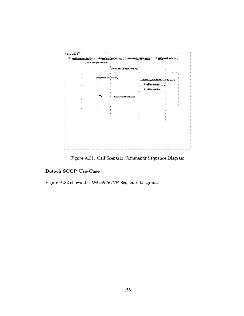
•Jimeraciioii2:
%.ijL?^j^mMan^i^i^'.7'1 r^ra^t f i^ facef^T^^vn. T^'iS'l^^J^^S^SSib^T'7) VWS^f^&^icgibh...'
1: sendManagerCommand
i : 1.1: forwardMaiiagerConnmand
: [sccpServlcelsAttached]
I : servicelsNotAttadied
lisetCallSoenarfoToTheManagdrCofraTiand
2: callScenarloReq fc =
3: caltScenartoReq
Figure A.31: Call Scenario Commands Sequence Diagram
Detach SCCP Use-Case
Figure A.32 shows the Detach SCCP Sequence Diagram.
155

I Interactions
®% ranapSimManage. •. I | ># ranaplnterfaceFonh:... )'' & rartaplnterfaceCOntro) let*i • # s c c p ! h t ^ a c ^ b r i t r o l t e . .
1: detachSCCPServiceCommand
l.l:forwardDetachSCCPSertficeConimand
[sccpServicelsAttached]
[else]
1 : detachSccpService
2: detachSccpService
1 : servlcelsNotAttached
2 : detacnSCCPServiceCommantf I
Figure A.32: Detach SCCP Sequence Diagram
A.3 UML Interfaces
UML Interfaces are model elements that define sets of operations that other classes
must implement. It is possible to use the interfaces in class diagrams to specify
a contract between the interface and the class that realizes the interface. Each
interface specifies a well-defined set of operations that have public visibility. Those
operations will be provided to another class through a " use" relationship.
In UML, we call the relationship between the interface and its implementing
class " interface realization" relationship.
This section shows the UML representation for all interfaces that have been
used to build the class diagram for the RanapSim Model, these interfaces are shown
156
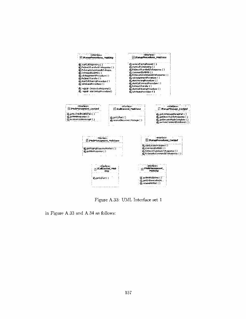
1 mmjpProceikires_l*lobOrig
$Jst*tC*3rigjnatiig ( ) ftfUOmXtTrarKferSsTitBespams ( ) ft&xS«urityCoHimarid8iT*ftespo... ftCornmonlDofiMSl ( ) fttabAsstgnmentProc*?dure ( ) ft,R»C*«tTr»«fet C S ftstatCalCteaiv^nxedu:* ( }
%«signah cmSer'&eRespenseO ^."'SgnahstatSetiEPjotedueO
__: . ' oiriteriace*1-B lRjnapProtedures^Moblerm
reci9veP3gsngRequest { ) JstartCalTefmsrBting ( ) JRxDieetTtswfa&TxResponse ( ) jCommoniDoWBi ( ) ^RxSscuftyCommand&T .esporKe { )
^startcaKMiTKctftiKeifciie I) JRxDtectTransfer ( ! ^st«CaKfeaiin#1iKecK«e ( )
*Mafaoi»'
R g e t t o c M p * * * W a t ( ) ^ getMrrtiespanse ( ) ^ locationUpdateAccept { )
"hl«face» t i ICaBContmi^Moblerm
^getCcPat (') UKeiveOsconnettMessage ( )
: •fit&Stfx&'r <M IRjruipMf!.SSiigt!_LocVpd
o $|getDirectTranfe!lte5pon$e ( ) ^getSecuityMcKteComplete ( )
: <||p fosmCornman!DQnRariap { )
H IMabMJtnagmeat_MobTerm
; ^getMmResporse C} i ^RjDrectTt«isfeiStT!iR«s»rse ( ) ; ^RscSecurityCommand&TsResponse { )
• «ihtetfke>> SB icoamtrolj*lob •* Orig
:'fe'fl»tCiiP*t() HgetMmRsspome ( ) ftgstCmSwiiceReqM-.-
: ftieceiveMmPart ( )
Figure A.33: UML Interface set 1
in Figure A.33 and A.34 as follows:
157

§ ICaMScenarios
gfocationUpdReq { )
a mabfeartgReq ( ) gtraisfeMfessageToMd^SijgSfrt i )
IjtraosferMiessageToMeMeTetmSim ( )
\-_;*Werte»-' " i l iRanapHessage
^recetveRanapPart ( } 3||getDirectTtanfe^espQnse( } ^perfcrn<DnfnronIDar*anap( } ^gett&ettTtarsfefRequest {}
^perfotmluReteaseCornmsxl ( ) ^perfonnSecMcdeCoimiad { )
if/OSPSystem
p'tartAita£hR*q"£) g,staitCppConr«KtR&q ( }
|5tartDetacN?*?<3 ( ) IstartCppDataRegi)
«fnCerfete**-'' UilICPPwiihQioc
l^connectRejO ^comectCfm {) ^data lnd{ ) % attachToSeJVKeCfm { ) ^& cfcclrtd ^ > H, detachFrcmSe?viteCfm ( )
"',..„. ^interface*' \ § manapControSer
^ ^wardManagaConimand { ) 5 to waf<UttathSCCfSeniceCommand { ) ^ forwatcDetachSCCPSefvJceCoTimand ( )
"**ifit9rf Ke»• I I IRanapFonn
^messageRaward C}
H TfraflkHmdfer
: ^<aftScerot9R«q't) : %trarwfeMe$s^ToHsoc8er {5
*friifc@rfaee» ' HXSCCP
^attacftSetpSenfce | \ ^ tf ansfert fessageToScep ( ) i &detachSccp5«j<rs»fce { js
:.V--'-*<int#face»" HI TfransferMessage
{j messaejeForwaid ( )
;*lnterte>* Wl iCpx&xpApfi
g. a^tacfttcSej-wc^eq { ) |,det3chFromSeivtoeReq | )
»in£erface>> IBlStATtTulM
. * interface*
'^tifansfaMessagetdSccp ( )
I J ICpxScd "Hiterrace» UlRefeaseMM
. ^reieaseMMcoiinec..
••'ftterfacfe*'"
; tf^nam^tessaoefoHanefts i )
Figure A.34: UML Interface set 2
158

A.4 CPP Platform Classes
This section illustrates two main classes that are provided by the CPP to commu
nicate with the SCCI and SccpApfi Interfaces, these classes illustrated as follows:
CpxScciApfiProxy:: CpxSccpApfiA ttachP
Figure A.35 shows the UML representation for this class.
BcpxSctpApfiAUachP ; '. CjjattachRef : KictentID
'''^'ktehfoSeiviceReq ()""' '; i i&ittaehTo&rviceOm ( ) gldetachfaomS^veceReq ( )
Figure A.35: CpxScciApfiProxy::CpxSccpApfiAttachP Class
Class Data Members: attachRef, clientID, and signalld.
Class operations:
CpxScciApfiProxy: :CpxSccpApfiAttachP::attachToServiceReq
CpxScciApfiProxy ::CpxSccpApfiAttachP::attachToServiceCfm
CpxScciApfiProxy ::CpxSccpApfiAttachP::detachFromServiceReq
CpxScciApfiProxy:: CpxSccpApfiAttachP: :detachFromServiceCfm
CpxScciProxy:: CpxScciP
Figure A.36 shows the UML representation for this class.
Class operations:
CpxScciProxy:: CpxScciP: :connectReq
CpxScciProxy:: CpxScciP r.connectCfm
CxScciProxy:: CpxScciP:: dataReq
CpxScciProxy:: CpxScciP r.datalnd
159

\ %comecH:fra ( )
I ijdatalnd ( ; i&dsd teq<) ; ftttectnd ( )
Figure A.36: CpxScciProxy::CpxScciP Class
CpxScciProxy:: CpxScciP: :discReq
160

Bibliography
[1] R. Miles and K. Hamilton. Learning UML 2.0. O'Reilly, 2006.
[2] J. Schmuller. Sams Teach Yourself UML in 24 Hours. Sams Publishing, 2004.
[3] IBM Corporation. Rational Systems Developer Tool, http://www.ibm.com,
2007.
[4] J. Rumbaugh, I. Jacobson, and G. Booch. The Unified Modeling Language
Reference Manual. Addison-Wesley, 2005.
[5] Ericsson Inc. CPP Platform Specification, SCCP Signaling Service Using
UML, Ericsson confidentainal information, 2007.
[6] 3GPP TS 25.413: Universal Mobile Telecommunications System (UMTS);
UTRAN Iu Interface Radio Access Network Application Part (RANAP) Sig
naling, version 5.12.0 Release 5, 2005.
[7] 3GPP TS 24.008: Digital cellular telecommunications system; Universal Mo
bile Telecommunications System (UMTS); Mobile radio interface Layer 3 spec
ification; Core network protocols; Stage 3, version 5.16.0 Release 5, 2006.
[8] H. Holma and A. Toskala. WCDMA for UMTS: Radio Access for Third Gen
eration Mobile Communications. John Wiley &, Sons, 2004.
161
[9] R. Kreher and T. Ruedebusch. UMTS Signaling: UMTS Interfaces, Protocols,
Message Flows and Procedures Analyzed and Explained. John Wiley & Sons,
2005.
[10] 3GPP TS 24.007: Digital cellular telecommunications system; Universal Mo
bile Telecommunications System (UMTS); Mobile radio interface signaling
layer 3; General Aspects; version 5.4.0 Release 5, 2005.
[11] 3GPP TS 25.410: Universal Mobile Telecommunications System (UMTS);
UTRAN Iu Interface: General Aspects and Principles; version 5.4.0 Release
5, 2004.
[12] 3GPP TS 25.412: Universal Mobile Telecommunications System (UMTS);
UTRAN Iu Interface signaling transport; version 5.2.0 Release 5, 2004.
[13] 3GPP TS 44.018: Digital cellular telecommunications system; Mobile radio in
terface layer 3 specification; Radio Resource Control (RRC) Protocol; version
5.22.0 Release 5, 2006.
[14] ITU-T Recommendation Q.711: Specifications of Signaling System No. 7 -
Signaling connection control part, functional description of the Signaling Con
nection Control Part, 1996.
[15] ITU-T Recommendation Q.714: Specifications of Signaling System No. 7 - Sig
naling connection control part, Signaling connection control part procedures,
1996.
[16] Ericsson Inc. MGwSim Simulator Architecture, Ericsson confidentainal infor
mation, 2005.
[17] X. Li, S. Li, C. Gorg, and A. Timm-Giel. Traffic Modeling and Characteriza
tion for UTRAN. In Wired/Wireless Internet Communications, LNCS 3970,
pp. 190-201, Springer-Verlag, 2006.
162

[18] D. Staehle, K. Leibnitz, and P. Tran-Gia. Source Traffic Modeling of Wireless
Applications. International Journal of Electronics and Communications, 55
(1): 27-36, 2001.
[19] A. Garcia, E. Garcia, M. Alvarez-Campana, J. Berrocal and E. Vazquez. A
Simulation Tool for Dimensioning and Performance Evaluation of the UMTS
Terrestrial Radio Access Network. In Interactive Distributed Multimedia Sys
tems and Protocols for Multimedia Systems: Protocols and Systems for Inter
active Distributed Multimedia, LNCS 2515, pp. 49-60, Springer-Verlag, 2002.
[20] S. Tabbane. Modelling the MSC/VLR processing load due to mobility man
agement. In Proceedings International Conference of Universal Personal Com
munications, volume 1, pp. 741-744, Florence, Italy, 1998.
[21] ITU-T Union. Worldwide mobile cellular subscribers to reach 4 billion mark
late 2008. http://www.itu.int/newsroom/press_releases/2008/29.html.
[22] B. Reed. Global telecom revenue to hit $2 trillion in '08, Network World,
http://www.networkworld.com/news/2008/091708-global-telecom.html.
[23] K. Prasad and K. Poon. Design of a protocol controller for wireless information
networks. In Proceedings Local Computer Networks, pp. 519-524, Minneapolis,
Minnesota, USA, 1992.
[24] T. Suzuki, S. Shatz, and T. Murata. A Protocol Modeling and Verification Ap
proach Based on a Specification Language and Petri Nets. IEEE Transactions
on Software Engineering, 16 (5): 523-536, 1990.
[25] J. Lee and P. Hsu. Design and Implementation of the SNMP Agents for Re
mote Monitoring and Control via UML and Petri Nets. IEEE Transactions
On Control Systems Technology. 12 (2): 293-302, 2004.
163

[26] V. Garousi, L. Briand, and Y. Labiche. Traffic-aware Stress Testing of Dis
tributed Systems Based on UML Models. In Proceedings International Con
ference on Software Engineering, pp. 391-400, Shanghai, China, 2006.
[27] Catapult Communications. MGTS System Reference Manual.
http://www.catapult.com/products/mgts.htm, 2007.
[28] Catapult Communications. DCT2000 System Reference Manual.
http://www.catapult.com/products/dct2000.htm, 2007.
[29] Polystar Inc. SOLVER System Information.
http://www.polystar.com/SOLVER system/Downloads/Post.aspx, 2007.
[30] Ericsson Inc. 3Gsim Solution, Confidential Information.
[31] Ericsson Inc. UTMS Solution, Confidential Information.
[32] D. Loukatos, L. Sarakis,K. Kontovasilis, C. Skianis, and G. Kormentzas. Tools
and Practices for Measurement-based Network Performance Evaluation. In
Proceedings Personal, Indoor and Mobile Radio Communications, pp. 1-5,
Athens, Greece, 2007.
[33] D. Loukatos, L. Sarakis, K. Kontovasilis, and N. Mitrou. An Efficient ATM
Traffic Generator for the Real-Time Production of a Large Class of Complex
Traffic Profiles. Journal of Communication and Networks. 7 (1): 54-64, 2005.
[34] O. Kone and R. Castanet. Test generation for interworking systems. Computer
Communications, 23 (7): 642-652, 2000.
[35] N. Celandroni, E. Ferro, and F. Potorti. A Traffic Generator for Testing Com
munication Systems: Presentation, Implementation and Performance. Real-
Time Systems, 13 (1): 5-24, 1997.
164

[36] V. Frost, B. Melamed. Traffic modeling for telecommunications networks.
IEEE Communications Magazine, 32 (3): 70-81, 1994.
[37] C. Barrett, M. Drozda, M. Marathe, S. Ravi, and J. Smit. A Mobility and
Traffic Generation Framework for Modeling and Simulating Ad hoc Commu
nication Networks. Scientific Programming, 12 (1): 1-23, 2004.
[38] F. Sandu, S. Cserey, I. Szekely, D. Robu, and T. Balan. Simulation of an ad
vanced mobile communication network. In Proceedings Optimization of Elec
trical and Electronic Equipment, pp. 223-230, Brasov, Romania, 2008.
[39] A. Varga. OMNeT++ Discrete Event Simulation System Version 3.2 User
Manual, www.omnetpp.org, 2005.
[40] 3GPP TS 23.205: Universal Mobile Telecommunications System (UMTS);
Bearer-independent circuit-switched core network; Stage 2, version 5.16.0 Re
lease 5, 2008.
[41] ITU-T Recommendation Q.711: Language and General Doftware Aspects for
Telecommunication Systems, Specification and Description Language (SDL),
1992.
[42] K. Konishi, K. Maeda, K. Sato, A. Yamasaki, H. Yamaguchi, T. Higashino,
and K. Yasumoto. MobiREAL Simulator - Evaluating MANET Applications
in Real Environments. In Proceedings Modeling, Analysis, and Simulation of
Computer and Telecommunication Systems, pp. 499-502, Washington, DC,
USA, 2005.
[43] M. Mackaya, O. Kone, and R. Castanet, Modeling Location Operations in
UMTS Networks. In Proceedings Modeling Analysis and Simulation of Wire
less and Mobile Systems, pp. 69-73, Atlanta, Georgia, USA, 2002.
165

[44] M. Mackaya and R. Castanet. Modeling and testing location based application
in UMTS networks. In Proceedings International Conference on Telecommu
nications, volume 1, pp. 189-195, Zagreb, Croatia, 2003.
[45] S. Rios. Location Based Services: Interfacing to a mobile Positioning Center.
www.wirelessdevnet.com/channels/lbs.
[46] 3GPP TS 23.171: Universal Mobile Telecommunications System (UMTS);
Functional description of location services; Stage 2, version 3.11.0, 2004.
[47] ITU-T Recommendation Z.120: Language and General Software Aspects for
Telecommunication Systems, Message Sequence Charts (MSC), 1993.
[48] R. Thomas, H. Gilbert, and G. Mazziotto. Influence of the Moving of the
Mobile Stations on the Performance of a Radio Mobile Cellular Network. In
Proceedings Digital Land Mobile Radio Communications, Copenhagen, Den
mark, 1988.
[49] T. Kim, Q. Yang, S. Park, and Y. Shin. SDL Design and Performance Evalu
ation of a Mobility Management Technique for 3GPP LTE Systems. In SDL
2007: Design for Dependable Systems, LNCS 4745, pp. 272-288, Springer,
2007.
[50] Ericsson Inc. Formal Check Process, Ericsson confidentainal information, 2005.
166